Investigation of drop coalescence via transient shape evolution: A sequential event. based approach. Chakraborty a *
|
|
|
- Matthew Dennis
- 6 years ago
- Views:
Transcription
1 Investigation of drop coalescence via transient shape evolution: A sequential event based approach Krishnayan Haldar a, Samarshi Chakraborty a, Manas Ranjan Behera a, Sudipto Chakraborty a * a Department of Chemical Engineering, IIT Kharagpur, Kharagpur , West Bengal, India *Corresponding author: Sudipto Chakraborty, Department of Chemical Engineering, IIT Kharagpur India. sc@che.iitkgp.ernet.in Phone (office):
2 ABSTRACT While a drop of liquid is placed on another liquid surface, two possible coalescence outcomes are observed. The parent drop bounces several times, floats and then disappears within the liquid pool without producing daughter droplets. This is called complete coalescence. Another outcome is the generation of secondary droplets from the primary drop itself. This is called partial coalescence. Repetitions of such phenomenon as a successive self-similar event is also known as coalescence cascade. In a nutshell, complete coalescence is governed strongly by swallowing mechanism whereas partial coalescence is attributed to slippage mechanism and solutal Marangoni flow. Here we use high speed camera and witness that water drop coalesces completely after impacting on pool of liquid whereas drop of non-ionic surfactant (TWEEN 20) coalesces partially. We also observe that number of daughter droplet generation is a strong function of surfactant concentration. Here we utilise the images to elaborately explain both the phenomenon in a sequential event based approach using the basic understanding of physics. We observe the transient evolution of drop morphology during each stage and find shape wise resemblances with many common objects. Our study reveals some interesting insight on the intermediate mechanisms and enlightens distinctive features of both the phenomena. Here we propose for the first time that additional instability due to slippage of rising water layer from the surfactant drop and upward thrust due to Laplace pressure helps in formation of secondary droplet. Keywords: Partial coalescence, complete coalescence, high speed camera, drop morphology, slippage, Laplace pressure. 2
3 I. INTRODUCTION Many natural occurrence like falling of rain drop 1, formation of cloud mist 2, vortices 3, mixing in microfluidic devices 4, foam formation 5 etc. are assumed as examples of coalescence process many years ago. Since, many researchers have looked into it theoretically and experimentally to have an insight of it. There are sequences of stages which occur before the drop merged with the bulk. The invention of high speed camera has enabled researchers to observe the complex mechanism of drop coalescence. The bigger drop falls with a low impact velocity 6, forms a crater on the water surface and then sinks within it quickly. Accordingly, due to opposite reaction force of the liquid pool the drop rebounds from the crater. Then the drop repetitively bounces until it gets stabilized on water surface. It was found from the study of Charles & Mason 7 that the drop rests over a very thin layer of air entrapped between drop and bulk interface. This entrapped air has a commanding role on duration of drop floatation on water surface 8. Subsequently, this weak layer of air drained away to aid in merging of drop and bulk liquid 9. Now, the liquid mass of drop has the chance to flow into the bulk water because of air drainage. As a result a capillary wave is generated across the periphery of the drop 10. It was also suggested that due to sudden water evacuation the droplet volume gets reduced, therefore creating a narrow neck immediately. The completion of narrowing increased the chance of pinch off. This process of generation of secondary droplets in six to eight steps due to partial coalescence is called coalescence cascade 11. The initial drop shape and the consecutive shape change from prolate to oblate or vice versa of falling drop played a role in generation of secondary droplets during partial coalescence 12. It was also suggested by the researchers, that dual secondary drops are generated from prolate shaped drops while only single drop is generated for oblate drops. Blanchette & Bigioni 13 showed that a race between rates of vertical and horizontal collapse of drop played a role in 3
4 partial coalescence. If the horizontal collapse rate succeeds over the vertical collapse rate, then it can produce a secondary droplet. Some researchers 11, have tried to explain dynamics of partial coalescence in absence of any surface active ingredients. Surface properties like elasticity, longitudinal viscosity and surface tension of surfactant influence in squeezing of drop at interface 17. Chen et al. 15 found that partial coalescence is mostly dependent on inertia and interfacial tension. They demarcated the whole phenomena into three regimes considering the effect of gravity and viscosity. It was observed from the study of Thoroddsen & Takehara 11 that the phenomenon is controlled by surface tension and inertia of drop while the viscosity has no contribution. The higher surface tension value of the reservoir fluid than the drop is a favourable condition for partial coalescence 18. It was observed from numerical results of Blanchette & Bigioni 19 that low viscous drops will be able to generate secondary droplets. Even the vertical velocity of secondary droplet after getting pinched off is also dependent on viscosity. Numerical results of Ray et al. 20 proved that partial coalescence is governed by inertia and interfacial tension forces while it is suppressed by viscous and gravity forces. Also the neck oscillation has a significant contribution in conversion from complete to partial coalescence. Martin et al. 21 have described recently the influence of surfactant concentration on forming coalescence cascade. The viscosity and the elasticity of surface tension of the drop play a major role behind this. Gilet et al 22 studied coalescence process by impinging drop at the interface of two different liquids. They suggested the process of coalescence has been influenced by viscosities and density differences of both the fluids. Hence lot of attempts have been made in recent past to explain coalescence phenomena; still many aspects of it remains opaque to scientific community. Here we found some new stages happening intermediately and going to propose a clear cut theory on it. We performed experiments using drop of water and non ionic surfactant impinged on bulk of water. We 4
5 observed complete coalescence for water drop and partial coalescence for surfactant drop. We also found a very interesting phenomenon that the number of droplet generation is dependent on surface tension of the impinging drops. II. EXPERIMENTAL SETUP A schematic diagram of the experimental set up has been shown in Fig.1 where a transparent glass beaker (Borosil) of 11.5 cm height and outside diameter of 86.8 mm and inside diameter of mm is used for all these experiments. Distilled water has been filled 3/5 th of total beaker volume to create the liquid pool. The beaker is placed on a laboratory jack which height can be adjusted by rotating a screw-handle. A micro syringe (Rame Hart ) having needle dimensions of 0.711mm outer diameter and inner diameters has been clamped with a stand above the liquid pool. The distance between needle tip and liquid surface has been kept 5 mm by adjusting the laboratory jack. The diameter of the drop depends on the needle diameter and liquid properties. This diameter is calculated by dropping 1 ml of volume for each solution and counting the number of drops. The height difference of 5 mm ensures gentle placing of liquid drop on air liquid interface and prevention of splashing. A high speed digital camera (Phantom V 7.3, Vision Research Inc. USA) is used to capture the drop impact dynamics. The video has been recorded in 512 x 384 resolutions at frames per second with exposure time of 69 µs. The image is maximum macro focused in accordance with 85X zoom and aperture opening between mm. For all the experiments scale has been fixed at mm/pixel. The camera is connected with a computer having in built software (Phantom PCC) by an Ethernet cable. The PCC software is kept opened during experimentation to observe the live video. The camera is kept in slight inclination of 5 o to capture the interfacial behaviour. A LED light 5
6 source (24 W) is kept behind the beaker (backlighting) with a glass diffuser in front of it. The diffuser is used to prevent over lighting which can make image unclear. The captured video is recorded in a data recording computer. The camera, computer and light source is connected to a common switch board. Trigger button of the PCC software is pressed as soon as the drop detaches from the needle. There is an extra pre-triggering option in the software which compensates minor time delay between event occurrence and switching of trigger. The recorded video is saved in.avi format and then cropped to eliminate unwanted parts. Then it is converted to images using free software Free Video to JPG Converter (DVDVideoSoft Ltd.). The images are analysed frame by frame to track the intermediate events of the phenomenon and processed accordingly. Necessary actions have been taken to avoid all possible experimental errors like needle and beaker vibration etc. We have used pure water and four different concentrations of non-ionic surfactant solution (TWEEN 20). TWEEN 20 (Polyoxyethylene sorbitan monolaurate; CAS Number: ; density gm/cm 3 ) has been procured from Merck, India. Distilled water of ph 5.6 has been used to prepare all solutions. The physical properties of each each solution have been displayed in Table 1. Surface tension, viscosity, specific gravity of solutions is measured using Du Nouy ring tensiometer (Testing Instruments, India), Parallel plate type viscometer (Brookfield DV-II+Pro) and Relative Density Bottles of 25ml, I/C Teflon Stopper (1625) (Borosil Glass Works Ltd.) 6
7 FIG. 1. Schematic diagram of experimental set up Table I: Diameter and physical properties of fluids of different concentrations used for these experiments. Concentration Surface tension Drop Viscosity Specific Gravity (ppm) (dyne/cm) diameter (mpa-s) (mm)
8 III. RESULTS AND DISCUSSION A. Complete Coalescence While a drop of water is impinged from a needle, it coalesces completely in the bulk liquid (water). Here, we explain the coalescence behaviour of the parent drop by dividing in nine physical stages. Images are obtained from captured high speed video and analysed frame by frame. 1. Floating of droplets: The liquid drop of water is gently impinged on the bulk of water and it is observed that the drop rests over the surface before sinking into the bulk (Fig. 2). This time duration is known as floatation time/ residence time. It is known from the literature that a thin layer of entrapped air provides the necessary cushion to make the drop float 8. The drop floats for 119 ms in this case. FIG.2. Floatation of impinging water drop 2. Rupture of Air film: The layer of air is very thin so it is quite unstable in nature and has possibility of getting ruptured. The rupture is due to the attractive Van der Waals interaction between the two interfaces of drop-air and liquid-air 23, 24 when its thickness is reduced below 100 nm. At first a hole is generated at the point of rupture (Fig. 3-a) when two interfaces merge together. Then the hole grows in size (Fig. 3-b) and propagates horizontally along the contact line (Fig. 3-c). As soon as the hole starts to propagate the drop bottom also merges with the bulk surface. Finally it is dissipated 8
9 completely (Fig. 3-d) to form a whole entity of drop and bulk. This event continues for ms. FIG.3. Rupture of air film entrapped between drop and liquid surface. Snapshots obtained from high speed movies showing the process for t = 0 ms (a), ms (b), ms (c), ms (d). 3. Rise of capillary wave: The rupture of air film generates a surface capillary wave which is able to rise up along the drop surface. The direction of movement of this wave is radially outwards along the initial flat interface 20. The following figures (Fig. 4-a c) represent the dynamics of capillary wave rise. The changing location of white area signifies the movement of wave front. This event continues for ms. which consists of corresponding sub events like generation, rise and final rise of the capillary wave. 9
10 FIG.4. Dynamics of capillary wave rise. Snapshots obtained from high speed movies showing the process for t = 0 ms (a), ms (b), 0.71 ms (c). 4. Creation of engulfing water layer: The following stage is supposed to be creation of layer of liquid from the bulk which will have tendency to engulf the drop. This stage is proposed by us for the first time which is the direct consequence of capillary wave rise. The energy carried by capillary wave is responsible for generation (Fig. 5-a) and rise of engulfing water layer. This layer will crawl over the drop gradually (Fig. 5-b) and will reach finally at the drop apex (Fig. 5-c). The interim shape change of drop takes place at ms while final rise of engulfing water layer takes place at ms. The final image shows a distortion of the original spherical form and a slight prick at the drop summit. FIG.5. Behaviour of engulfing water layer. Snapshots obtained from high speed movies showing the process for t = 0 ms (a), ms (b), ms (c). 5. Drainage of drop: The sequential rise of capillary wave and engulfing water layer both impart a downward pressure on the drop (Fig. 6-a). This results in gravity driven 10
11 flow from the drop through the interface. The drop takes different shapes and consequent physical sub events happened intermediately. All the sub events are discriminated by observing the shape change of drop apex. The result of applied pressure is dip down of peak (Fig. 6-b), and peak flattening (Fig. 6-c). Suddenly another secondary peak starts to rise from that site (Fig. 6-d) and quickly gets flattened out (Fig. 6-e). The gravity driven flow is completed at ms when we observe the total suppression of secondary peak (Fig. 6-f). It is prominent that not the whole drop rather a part of it is drained out by the action of gravity. FIG.6. Flow of liquid through ruptured interface. Snapshots obtained from high speed movies showing the process for t = 0 ms (a), ms (b), ms (c), ms (d), 0.71 ms (e), ms (f). 6. Swallowing: The major reason of complete coalescence is the swallowing stage which takes place just after the drainage of the drop. The continuous mass loss because of downward flow makes it easier to get it swallowed by engulfing layer. The engulfing water layer will rise above the drop and will try to swallow it completely. This event continues for ms where engulfing layer of water gulps the whole 11

12 drop of water. The visible change in drop shape is observed and demonstrated in the following figures ((Fig. 7 a-c). The top notch part of the drop changes its shape. Initially it was a bit flat whereas at later stages it converges to a pin like profile. FIG.7. Dynamics of drop swallowing by engulfing water layer. Snapshots obtained from high speed movies showing the process for t = 0 ms (a), ms (b), ms (c). 7. Narrowing of swallowed drop: Another significant shape change of drop occurs at this event. The drop acquires various shapes as displayed below. The drop is narrowed from both sides as a consequence of Laplace pressure ( P P P 2 / R ) generated upward thrust. Laplace pressure is the difference in out between inside and outside pressure of the drop respectively across curved liquid air interface which originates because of surface tension. The outward thrust will force the drop gets narrowed at interface (Fig. 8-a). As it is narrowed from both sides, a neck is erupted vertically (Fig. 8-b) from the drop (0.284 ms). Slowly its neck is elongated (Fig. 8-c) and a nipple like shape is appeared (Fig. 8-d). This nipple seems to get pinned at its interface with bulk (Fig. 8-e). Pinning is a physical process where the body of the drop gets attached with the liquid pool. This stage lasts for 1.42 ms when the swallowed drop narrowed totally (Fig. 8-f). 12
13 FIG.8. Morphology of drop during narrowing. Snapshots obtained from high speed movies showing the process for t = 0 ms (a), ms (b), ms (c), ms (d), ms (e), 1.42 ms (f). 8. Gradual collapse of liquid drop: A competition will act between outward Laplace pressure and downward engulfing pressure. The extent of engulfing pressure suppresses the effect of thrust of Laplace pressure completely. Therefore, the drop gets reduced in height and starts to collapse within the pool. The mechanism is schematically illustrated in Fig. 9. It takes a form of small pillar at the end of squeezing (Fig. 10-a). The pinning effect is solely responsible for creating a pillar like formation. The height of the drop pillar slowly reduces (Fig. 10-b), pins (Fig. 10-c) and then starts to collapse (Fig. 10-d). This collapse is due to cumulative effects of engulfing, swallowing and downward gravity driven flow. Actually the drop sinks within the basin (Fig. 10-f) and the whole event takes much higher time (3.124 ms) for completion. 13
14 FIG.9. Schematic illustration of competitive effect between engulfing pressure and upward thrust of Laplace Pressure leading to drop collapse FIG.10. Collapse of liquid drop after narrowing. Snapshots obtained from high speed movies showing the process for t = 0 ms (a), ms (b), ms (c), ms (d), ms (e), ms (f). 9. Collapse of drop: This image is taken immediately after the final collapsing stage. The just risen peak of the column instantaneously falls to produce complete 14
 on the bulk liquid.")
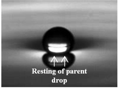
15 coalescence (Fig. 11). Hence, no daughter droplet generation is possible for this situation. FIG.11. Collapse of water drop within pool of water. B. Partial Coalescence While a drop of surfactant solution is impinged from a needle, it coalesces partially for four to five times (depending on concentration) on the bulk liquid. Here, we explain the first coalescence behaviour of the parent drop by dividing in ten physical stages and assume rest of the secondary drops follows similar coalescence behaviour. Images are obtained from captured high speed video and analysed frame by frame. 1. Resting of surfactant covered drops: The surfactant laden drop is gently deposited on the liquid pool. It tends to float on the surface for quite some time before the start of coalescence (Fig. 12); the nature of floatation on the entrapped air layer is similar to the phenomenon explained for resting of water drop. Resting of drops is the first and foremost stage of coalescence. The drop floats for ms for this case. 15
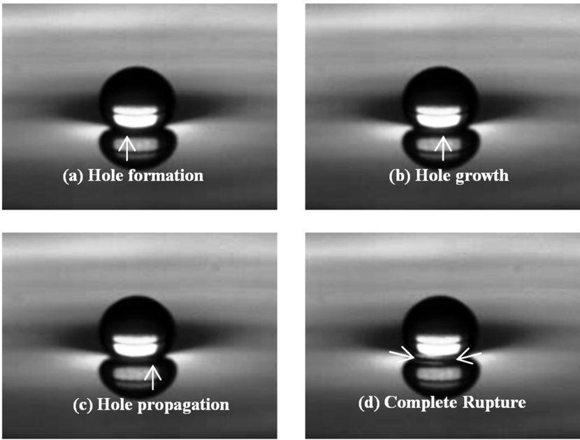
16 FIG.12. Floatation of impinging surfactant laden water drop 2. Rupture of entrapped air layer: The rupture of entrapped thin layer of air ruptures in the similar fashion as described earlier. Initially a hole is generated (Fig.13-a) which grows (Fig.13-b), propagates horizontally (Fig.13-c) and then finally completely dissipates away (Fig. 13-d). Thus the drop merges with the liquid pool to make a complete entity. The total time taken for rupture of air film for this case is ms. FIG.13. Rupture of air film entrapped between drop and liquid surface. Snapshots obtained from high speed movies showing the process for t = 0 ms (a), ms (b), ms (c), ms (d). 16
17 3. Rise of capillary wave: The subsequent effect of capillary wave rise due to rupture of film also follows the same mechanism like it happens over water drop. A vertical capillary wave generates (Fig. 14-a), rises, crawls (Fig. 14-b) over the drop body and finally it ends (Fig. 14-c). The wave propagation is observed in the following images. The important thing is that the drop shape doesn t change at all while a reflecting layer just changes its location across the drop periphery. The capillary wave takes ms to rise across the drop. FIG.14. Process of formation and rise of capillary wave. Snapshots obtained from high speed movies showing the process for t = 0 ms (a), ms (b), ms (c). 4. Rise of engulfing water layer: Similarly, as explained for water drop incident a thin layer of water from the bulk is created which has a general affinity to swallow the drop. The rise of water layer over the drop is clearly visible from the following images. The drop shape is changed notably at ms due to summit reach of engulfing layer (Fig. 15 a-c). 17
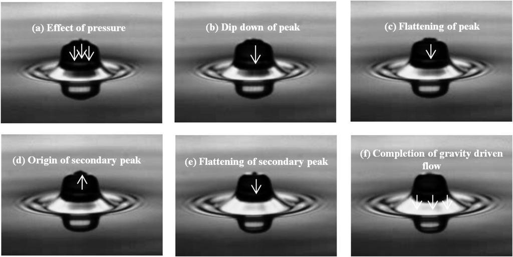
18 FIG.15. Behaviour of engulfing water layer. Snapshots obtained from high speed movies showing the process for t = 0 ms (a), 0.71 ms (b), ms (c). 5. Gravity driven flow along with diffusion: The rise of engulfing water layer will pressurize the drop fluid to drain down (Fig. 16-a). Although the drop will drain due to action of gravity, there will also be an action of concentration driven Marangoni flow or solutal Marangoni effect 25, 26. It is quite evident that concentration varies at drop-bulk interface because of presence of surfactants in the drop. Hence, a surface tension gradient acts at interface which aids in origin of Marangoni flow. This flow involves mass transfer in the form of diffusion through the interface. This is the stage which differentiates from the water drop draining. Similar observations of primary peak dipping (Fig. 16-b), primary peak flattening (Fig. 16-c), secondary peak generation (Fig. 16-d) and its flattening (Fig. 16-e) are observed like in the previous case. The total time taken to complete (Fig. 16-f) this gravity driven and concentration driven flow is ms. 18

19 FIG.16. Flow of liquid through ruptured interface. Snapshots obtained from high speed movies showing the process for t = 0 ms (a), ms (b), ms (c), ms (d), ms (e), ms (f). 6. Slippage of water layer: Although the engulfing water layer will rise over the drop, still it will not gulp the underlying drop like in case for water drop. Rather it will slip from the surface of the drop across the periphery. Here we report the occurrence of slippage mechanism for the first time in context of partial coalescence. The mechanism of slippage from the surface is explained schematically in the Fig. 17. The surfactant molecules orient itself in the drop air interface by keeping the hydrophobic tail hanging in the air while the hydrophilic head inserted within the bulk. The moment the layer of engulfing water climbs around the surface, it will be repelled by wagging hydrophobic tail. Therefore, the layer can t climb completely and slide from the surrounding of the drop. The slippage of engulfing water layer is the determining factor for partial coalescence. The images obtained from high speed camera are displayed (Fig. 18 a-c) to calculate the time of the event (0.568 ms). The periodic suppression and opening of peaks imply the progress of slippage. FIG.17. Schematic illustration of hydrophobic repulsion by tail to initiate slippage 19
20 FIG.18. Dynamics of slippage mechanism of engulfing water layer over the drop. Snapshots obtained from high speed movies showing the process for t = 0 ms (a), ms (b), ms (c). 7. Formation of column: The stage which follows the slippage is also contributing to the partial coalescence. In this stage drop takes a shape of column. A tip is erupted from the drop vertically (Fig. 19-a), which elongates further (Fig. 19-b) and finally the drop appears as a column (Fig. 19-c). The whole event takes place for ms. FIG.19. Dynamics of column formation. Snapshots obtained from high speed movies showing the process for t = 0 ms (a), ms (b), ms (c), 1.136ms. 8. Column thinning: The drop will slowly be reduced in mass because of solutal Marangoni flow. Marangoni flow will create an interfacial instability 27. Also Laplace 20
21 pressure ( P P P 2 / R ) which is the pressure difference between inside and in out outside drop pressure respectively comes will apply a thrust outwardly. These two actions will help in thinning of column (Fig. 20 a-c). FIG.20. Dynamics of column thinning. Snapshots obtained from high speed movies showing the process for t = 0 ms (a), ms (b), ms (c). 9. Neck thinning: This stage is the longest among all and consists of various sub stages. As we explained earlier that Laplace pressure induced thrust will push the drop vertically upwards while the Marangoni stress induced flow will make it weaker at interface. These two acts as a tearing action for the drop which are schematically illustrated in Fig. 21. The cap shaped drop will squash (Fig. 22-a) first to get narrowed down at neck (Fig. 22-b). After few milliseconds a concave interface (Fig. 22-c) will be formed at the junction of drop and bulk. Gradually the drop will take a shape of parachute (Fig. 22- d) and start to fall down (Fig. 22-e) along with the interface. The wider neck will be further crushed (Fig. 22-f) to form a thin strip. Then it will again change in the shape of balloon (Fig. 22-g). The balloon shaped drop will be deformed further (Fig. 22-h) to reach a stage of pinching off (Fig. 22-i). 21


22 FIG.21. Schematic illustration of effect of Laplace pressure and Marangoni flow generated instability on drop neck thinning. 22
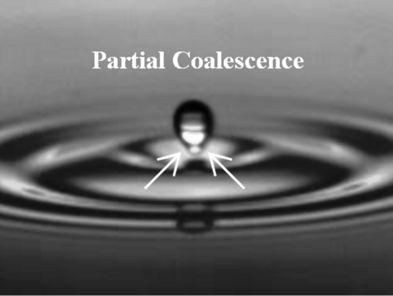
23 FIG.22. Morphological evolution of drop during thinning. Snapshots obtained from high speed movies showing the process for t = 0 ms (a), 0.71 ms (b), ms (c), ms (d), ms (e), ms (f), ms (g), ms (h), ms (i). 10. Detachment of daughter droplets: The already pinched off drop detaches from the thin little strip and will give a secondary droplet (See Fig. 23). It pops from the surface and bounces similarly to give another set of partial coalescence. FIG.23. Partial coalescence of surfactant laden water drop within pool of water. C. Coalescence Cascade After impact, surfactant laden water drop coalesces partially i.e. jumps, floats and breaks up into another drop. This phenomenon of partial coalescence occurs in self similar manner repetitively in a series. The behaviour of coalescence cascade is observed for four times (36 ppm) and for five times (73, 730, 3650 ppm). Each of the outcomes of the cascade for surfactant concentration of 73 ppm is depicted in Fig. 24. (a e). It is observed that drops are getting smaller in size at the end of each partial coalescence. The smallest drop (Fig. 24-e) coalesces completely in the same process as earlier explained. Similar images are obtained for drop of 36.5 ppm concentration only difference is its number. 23
24 FIG. 24. Successive generation of secondary droplets for surfactant drop (CMC) (a) Primary drop; (b) Secondary drop; (c) Tertiary drop; (d) Quaternary drop; (e) Pentanary drop. D. Effect of concentration on coalescence time An extensive frame wise analysis of the video helps in calculating time taken for each coalescence event. Figure 25 shows the variation of coalescence time for each of the drop at all surfactant concentrations. It is seen that coalescence time is getting reduced in succession along with reducing drop sizes. It is known from the expression of Laplace pressure, smaller drops (drops of reduced diameter) experience more thrust of Laplace pressure as it is inversely proportional with radius. Hence, secondary droplets require shorter time to coalesce. 24
 solution.")
25 FIG. 25. Effect of concentration on individual coalescence time IV. CONCLUSION We have performed experiments on liquid drop impacting on liquid pool by using water and four different concentrations of surfactant (TWEEN 20) solution. Using high speed photography we observe that upon impinging on a pool of water, a water drop doesn t break up into a secondary droplet whereas a surfactant laden drop can break into a series of daughter droplets. We split the whole phenomenon in distinct stages sustaining for definite time duration and narrate it qualitatively which are not found in existing literatures. Here we propose some new mechanisms influencing the coalescence phenomena by applying common knowledge of physics. Intermediately, we observe the change in drop shape in various substages. Two phenomena resulting from a liquid drop impinging on a liquid pool have been discussed elaborately by splitting in many stages occurring at definite time intervals. Complete 25
26 coalescence of water drop takes place in nine stages whereas partial coalescence of surfactant laden drop takes place in ten stages. We can summarise the whole events in few points: (a) Initial four events (up to rise of engulfing water layer) are common for both the phenomena. Difference starts from fifth event for surfactant drop where a mass diffusion driven by concentration gradient along with downwards gravity driven flow occurs through interface. (b) Complete coalescence is governed strongly by swallowing mechanism. Upward thrust due to Laplace pressure acts as the source of detachment but it is dominated completely by downward impact due to engulfing pressure. Marangoni stress is not acting in this case as solutal Marangoni flow is absent across the interface. Hence, engulfing pressure pushes the drop downwards. The drop remained pinned with the bulk to stay as a fluid body. This drop later gradually sinks within the pool to coalesce completely. (c) Swallowing event is replaced by slippage of engulfing water layer for surfactant laden drop. We define slippage as repulsion of water layer by hydrophobic tail of surfactant molecule. Successively all the following stages are characteristically different contrary to complete coalescence. Slippage of water layer creates an additional interfacial instability outside along with solutal Marangoni flow which takes place through the interface inside the drop. Simultaneously, thrust generated because of Laplace pressure across the drop circumference pushes it upwards continuously. These both ways tearing action (Laplace pressure in upward direction and Marangoni flow in downward direction) leads to thinning and necking of drop. Hence, the drop will get detached easily from the interface. 26
27 (d) Physically surfactant covered drop is smaller in size than water drop owed to lower surface tension values 28 (See Table 1). Therefore, the parent surfactant drop always feels a stronger Laplace pressure driven upward thrust than water drop. Hence, presence of surfactant make drop more susceptible to partial coalescence. (e) It is obvious that Laplace pressure increases with reducing drop size after each detachment. The detachment of drop at the end of partial coalescence makes further small droplet. Also certain amount of dilution increases its surface tension value. Hence, the upward thrust is also getting stronger which helps in further and faster detachment of droplets and occurrence in partial coalescence. We show that coalescence time is getting shorter for secondary droplets. Also, we suggest that drop can t be pinned at the interface with bulk because both the liquids are different. Hence, the flow due to concentration difference will resist the drop to get pinned rather make it prone to instability and detachment. (f) We propose that the secondary daughter drop has reduced concentration gradient with the bulk liquid. However, it is sufficient for having Marangoni flow. Thus the partial coalescence will occur repetitively until concentration difference diminishes at the final smallest droplet, when it coalesces completely. At this instance drop concentration becomes similar to that of water. As we know surface tension becomes constant beyond CMC so the cascade of dilution will happen in self-similar manner for remaining surfactant concentration, at and beyond CMC. Similarly, the daughter droplet generation will be same in number which was shown earlier (See Fig. 25). This water like situation arrives at fifth stage of cascade for 73, 730, 3650 ppm but at fourth stage for 36.5 ppm surfactant concentration. 27
28 REFERENCES 1. H. T. Ochs, K. V. Beard, R. R. Czys, N. F. Laird, D. E. Schaufelberger, and D. J. Holdridge, "Collisions between Small Precipitation Drops. Part I: Laboratory Measurements of Bounce, Coalescence, and Temporary Coalescence," Journal of the Atmospheric Sciences 52, 2258 (1995). 2. E. X. Berry, and R. L. Reinhardt, "An Analysis of Cloud Drop Growth by Collection: Part III. Accretion and Self-collection," Journal of the Atmospheric Sciences 31, 2118 (1974). 3. J. J. Thomson, and H. F. Newall, "On the Formation of Vortex Rings by Drops Falling into Liquids, and Some Allied Phenomena," Proceedings of the Royal Society of London 39, 417 (1885). 4. H. A. Stone, A. D. Stroock, and A. Ajdari, "Engineering Flows in Small Devices," Annual Review of Fluid Mechanics 36, 381 (2004). 5. A. Bhakta, and E. Ruckenstein, "Decay of standing foams: drainage, coalescence and collapse," Advances in colloid and interface science 70, 1 (1997). 6. R.M.Schotland, "Experimental results relating to the coalescence of water drops with water surfaces," Discuss. Faraday Soc. 6 (1960). 7. G. E. Charles, and S. G. Mason, "The coalescence of liquid drops with flat liquid/liquid interfaces," Journal of Colloid Science 15, 236 (1960). 8. S. T. Thoroddsen, T. G. Etoh, and K. Takehara, "Air entrapment under an impacting drop," Journal of Fluid Mechanics 478, (2003). 9. G. E. Charles, and S. G. Mason, "The mechanism of partial coalescence of liquid drops at liquid/liquid interfaces," Journal of Colloid Science 15, 105 (1960). 10. I. S. Klyuzhin, F. Ienna, B. Roeder, A. Wexler, and G. H. Pollack, "Persisting Water Droplets on Water Surfaces," The Journal of Physical Chemistry B 114, (2010). 11. S. T. Thoroddsen, and K. Takehara, "The coalescence cascade of a drop," Physics of Fluids 12, 1265 (2000). 12. G. Biswas, B. Ray, and A. Sharma, Effect of Drop Shape on Partial Coalescence (REPINO, RUSSIA, 2011). 13. F. Blanchette, and T. P. Bigioni, "Partial coalescence of drops at liquid interfaces," Nat Phys 2, 254 (2006). 14. H. Aryafar, and H. P. Kavehpour, "Drop coalescence through planar surfaces," Physics of Fluids 18, (2006). 28
29 15. X. Chen, S. Mandre, and J. J. Feng, "Partial coalescence between a drop and a liquidliquid interface," Physics of Fluids 18, (2006). 16. B. Ray, G. Biswas, and A. Sharma, "Bubble pinch-off and scaling during liquid drop impact on liquid pool," Physics of Fluids 24, (2012). 17. P. Pikhitsa, and A. Tsargorodskaya, "Possible mechanism for multistage coalescence of a floating droplet on the air/liquid interface," Colloids and Surfaces A: Physicochemical and Engineering Aspects 167, 287 (2000). 18. F. Blanchette, L. Messio, and J. W. M. Bush, "The influence of surface tension gradients on drop coalescence," Physics of Fluids 21, (2009). 19. F. Blanchette, and T. P. Bigioni, "Dynamics of drop coalescence at fluid interfaces," Journal of Fluid Mechanics 620, 333 (2009). 20. B. Ray, G. Biswas, and A. Sharma, "Generation of secondary droplets in coalescence of a drop at a liquid liquid interface," Journal of Fluid Mechanics 655, 72 (2010). 21. D. W. Martin, and F. Blanchette, "Simulations of surfactant effects on the dynamics of coalescing drops and bubbles," Physics of Fluids 27, (2015). 22. T. Gilet, K. Mulleners, J. Lecomte, N. Vandewalle, and S. Dorbolo, "Critical parameters for the partial coalescence of a droplet," Physical Review E 75, (2007). 23. P.-S. Hahn, J.-D. Chen, and J. C. Slattery, "Effects of London-van der Waals forces on the thinning and rupture of a dimpled liquid film as a small drop or bubble approaches a fluid-fluid interface," AIChE Journal 31, 2026 (1985). 24. M. Sveier, "Study of the Droplet-Interface Dynamics Related to Liquid-Liquid Separators," Norwegian University of Science and Technology, S. Bekki, M. Vignes-Adler, E. Nakache, and P. M. Adler, "Solutal Marangoni effect: I. Pure interfacial transfer," Journal of colloid and interface science 140, 492 (1990). 26. S. Bekki, M. Vignes-Adler, and E. Nakache, "Solutal marangoni effect: II. Dissolution," Journal of colloid and interface science 152, 314 (1992). 27. X. Fanton, and A. M. Cazabat, "Spreading and Instabilities Induced by a Solutal Marangoni Effect," Langmuir : the ACS journal of surfaces and colloids 14, 2554 (1998). 28. R. C. Tolman, "The Effect of Droplet Size on Surface Tension," The Journal of Chemical Physics 17, 333 (1949). 29
30 LIST OF FIGURES FIG. 1. Schematic diagram of experimental set up FIG.2. Floatation of impinging water drop FIG.3. Rupture of air film entrapped between drop and liquid surface. Snapshots obtained from high speed movies showing the process for t = 0 ms (a), ms (b), ms (c), ms (d). FIG.4. Dynamics of capillary wave rise. Snapshots obtained from high speed movies showing the process for t = 0 ms (a), ms (b), 0.71 ms (c). FIG.5. Behaviour of engulfing water layer. Snapshots obtained from high speed movies showing the process for t = 0 ms (a), ms (b), ms (c). FIG.6. Flow of liquid through ruptured interface. Snapshots obtained from high speed movies showing the process for t = 0 ms (a), ms (b), ms (c), ms (d), 0.71 ms (e), ms (f). FIG.7. Dynamics of drop swallowing by engulfing water layer. Snapshots obtained from high speed movies showing the process for t = 0 ms (a), ms (b), ms (c). FIG.8. Morphology of drop during narrowing. Snapshots obtained from high speed movies showing the process for t = 0 ms (a), ms (b), ms (c), ms (d), ms (e), 1.42 ms (f). FIG.9. Schematic illustration of competitive effect between engulfing pressure and upward thrust of Laplace Pressure leading to drop collapse. 30
31 FIG.10. Collapse of liquid drop after narrowing. Snapshots obtained from high speed movies showing the process for t = 0 ms (a), ms (b), ms (c), ms (d), ms (e), ms (f). FIG.11. Collapse of water drop within pool of water. FIG.12. Floatation of impinging surfactant laden water drop FIG.13. Rupture of air film entrapped between drop and liquid surface. Snapshots obtained from high speed movies showing the process for t = 0 ms (a), ms (b), ms (c), ms (d). FIG.14. Process of formation and rise of capillary wave. Snapshots obtained from high speed movies showing the process for t = 0 ms (a), ms (b), ms (c). FIG.15. Behaviour of engulfing water layer. Snapshots obtained from high speed movies showing the process for t = 0 ms (a), 0.71 ms (b), ms (c). FIG.16. Flow of liquid through ruptured interface. Snapshots obtained from high speed movies showing the process for t = 0 ms (a), ms (b), ms (c), ms (d), ms (e), ms (f). FIG.17. Schematic illustration of hydrophobic repulsion by tail to initiate slippage FIG.18. Dynamics of slippage mechanism of engulfing water layer over the drop. Snapshots obtained from high speed movies showing the process for t = 0 ms (a), ms (b), ms (c). FIG.19. Dynamics of column formation. Snapshots obtained from high speed movies showing the process for t = 0 ms (a), ms (b), ms (c), 1.136ms. 31
32 FIG.20. Dynamics of column thinning. Snapshots obtained from high speed movies showing the process for t = 0 ms (a), ms (b), ms (c). FIG.21. Schematic illustration of effect of Laplace pressure and Marangoni flow generated instability on drop neck thinning. FIG.22. Morphological evolution of drop during thinning. Snapshots obtained from high speed movies showing the process for t = 0 ms (a), 0.71 ms (b), ms (c), ms (d), ms (e), ms (f), ms (g), ms (h), ms (i). FIG.23. Partial coalescence of surfactant laden water drop within pool of water. FIG.24. Successive generation of secondary droplets for surfactant drop (CMC) (a) Primary drop; (b) Secondary drop; (c) Tertiary drop; (d) Quaternary drop; (e) Pentanary drop. FIG.25. Effect of concentration on individual coalescence time. List of Tables Table 1: Diameter and physical properties of individual drop for different concentration Table 2: Non-dimensional numbers related to drop physical properties Nomenclature CMC: Critical Micelle Concentration P out : Outside pressure of drop P in : Inside pressure of drop : Static Surface Tension of the liquid contained in drop 32
33 R: Radius of drop Supplementary Information (SI) Table 2: Non-dimensional numbers related to drop physical properties Movie S1: Video for water drop impinging on pool of water; duration of video is s Movie S2: Video for surfactant laden water drop (CMC) impinging on pool of water; duration of video is s 33

34
35
36
37
38
39
40
41
42
43
44
45
46
47
48
49
50
51

52
53
54
55
56

57
58
COALESCENCE PHENOMENON AT THE INTERFACE BETWEEN IMMISCIBLE FLUIDS. Keywords: coalescence, immiscible fluids, interface, vortex ring.
 U.P.B. Sci. Bull., Series D, Vol. 78, Iss. 3, 2016 ISSN 1454-2358 COALESCENCE PHENOMENON AT THE INTERFACE BETWEEN IMMISCIBLE FLUIDS Ioana - Laura OMOCEA 1, Claudiu PATRASCU 2, Mona MIHAILESCU 3, Corneliu
Experimental Study of the Phenomenon of Droplet Impact upon a Liquid Surface
 Journal of Applied Fluid Mechanics, Vol. 9, No. 2, pp. 757-765, 2016. Available online at www.jafmonline.net, ISSN 1735-3572, EISSN 1735-3645. Experimental Study of the Phenomenon of Droplet Impact upon
Stability of Food Emulsions (2)
") Stability of Food Emulsions (2) David Julian McClements Biopolymers and Colloids Laboratory Department of Food Science Droplet Coalescence Oiling Off Coalescence Aggregation due to fusing together of two
Stability of Food Emulsions (2) David Julian McClements Biopolymers and Colloids Laboratory Department of Food Science Droplet Coalescence Oiling Off Coalescence Aggregation due to fusing together of two
A guide to droplet generation
 A guide to droplet generation 2 Contents INTRODUCTION... 4 Droplet generators... 4 A choice of designs... 4 DROPLET GENERATION... 5 Droplet generator geometry... 5 Flow rate control... 5 Droplet sizes
LOS 1 LASER OPTICS SET
 LOS 1 LASER OPTICS SET Contents 1 Introduction 3 2 Light interference 5 2.1 Light interference on a thin glass plate 6 2.2 Michelson s interferometer 7 3 Light diffraction 13 3.1 Light diffraction on a
Figure 1: A detailed sketch of the experimental set up.
 Electronic Supplementary Material (ESI) for Soft Matter. This journal is The Royal Society of Chemistry 2015 Supplementary Information Detailed Experimental Set Up camera 2 long range objective aluminum
RPA. Supplementary information
 Electronic Supplementary Material (ESI) for Lab on a Chip. This journal is The Royal Society of Chemistry 2015 Centrifugal step emulsification applied for absolute quantification of nucleic acids by digital
Final Report Summer Jefferson Taft 08/22/2003
 Final Report Summer 20003 Jefferson Taft 08/22/2003 There were two purposes to this research. One was to continue the whip project that was begun in the Fall, and the other was to develop experiments to
Droplet Size Measurement of Liquid Atomization by Immersion Liquid Method
 The 3rd International Conference on Design Engineering and Science, ICDES 2014 Pilsen, Czech Republic, August 31 September 3, 2014 Droplet Size Measurement of Liquid Atomization by Immersion Liquid Method
REFLECTION THROUGH LENS
 REFLECTION THROUGH LENS A lens is a piece of transparent optical material with one or two curved surfaces to refract light rays. It may converge or diverge light rays to form an image. Lenses are mostly
2-10 µm Diameter Water Droplets in Mineral Oil Emulsion Production
 2-10 µm Diameter Water s in Mineral Oil Emulsion Production Dolomite s Generation System - Small s Application Note Page SHPT-487168127-264_v.2.0 Summary 2 Flow Focussing Based Production 3 Experimental
FTA4000 Epson Ink Jetting
 FTA4000 Epson Ink Jetting 14 August 2007 The FTA4000 is now equipped with a dual-mode dispenser. This can operate with traditional pendant drop and spherical cap touch-off, or it can function as a true
Experiment and Numerical Simulation of Droplet Impact on a Sphere Particle
 International Journal of Research in Engineering and Science (IJRES) ISSN (Online): 2320-9364, ISSN (Print): 2320-9356 Volume 4 Issue 4 ǁ April. 2016 ǁ PP.25-31 Experiment and Numerical Simulation of Droplet
Droplet size measurement of liquid atomization by the immersion liquid method (droplet coalescence and solution into the immersion liquid)
") Advances in Fluid Mechanics X 191 Droplet size measurement of liquid atomization by the immersion liquid method (droplet coalescence and solution into the immersion liquid) T. Fujimatsu, M. Kito & K. Kondo
Advances in Fluid Mechanics X 191 Droplet size measurement of liquid atomization by the immersion liquid method (droplet coalescence and solution into the immersion liquid) T. Fujimatsu, M. Kito & K. Kondo
Module 2 WAVE PROPAGATION (Lectures 7 to 9)
") Module 2 WAVE PROPAGATION (Lectures 7 to 9) Lecture 9 Topics 2.4 WAVES IN A LAYERED BODY 2.4.1 One-dimensional case: material boundary in an infinite rod 2.4.2 Three dimensional case: inclined waves 2.5
Module 2 WAVE PROPAGATION (Lectures 7 to 9) Lecture 9 Topics 2.4 WAVES IN A LAYERED BODY 2.4.1 One-dimensional case: material boundary in an infinite rod 2.4.2 Three dimensional case: inclined waves 2.5
DP-8 H. H. MØRCH. Instructions. Contents of the packing. Spatial requirements. Mounting the bush
 DP-8 Instructions H. H. MØRCH Contents of the packing In the packing of the tonearm you will find the arm base in which the bearings are encapsulated in a heavy body. This is the link between the moveable
PHYS 3153 Methods of Experimental Physics II O2. Applications of Interferometry
 Purpose PHYS 3153 Methods of Experimental Physics II O2. Applications of Interferometry In this experiment, you will study the principles and applications of interferometry. Equipment and components PASCO
Lenses- Worksheet. (Use a ray box to answer questions 3 to 7)
") Lenses- Worksheet 1. Look at the lenses in front of you and try to distinguish the different types of lenses? Describe each type and record its characteristics. 2. Using the lenses in front of you, look
Lenses- Worksheet 1. Look at the lenses in front of you and try to distinguish the different types of lenses? Describe each type and record its characteristics. 2. Using the lenses in front of you, look
Interference Pattern of a Thinning Soap Film
 Interference Pattern of a Thinning Soap Film Nicholas Travers - - - Get Wet Assignment Flow Visualization 2012 1 Page Nicholas Travers An investigation was undertaken to observe and capture the colorful
Experimental Investigation of Viscous Liquid Jet Transitions
 ILASS Americas, 25 th Annual Conference on Liquid Atomization and Spray Systems, Pittsburgh, PA, May 2013 Experimental Investigation of Viscous Liquid Jet Transitions S. Ramalingam 1*, M. D. Cloeter 1,
This is an author produced version of Asphaltene-stabilized emulsions: an interfacial rheology study.
 This is an author produced version of Asphaltene-stabilized emulsions: an interfacial rheology study. White Rose Research Online URL for this paper: http://eprints.whiterose.ac.uk/94812/ Proceedings Paper:
AEROSOL JET PRINTING SYSTEM FOR HIGH SPEED, NON-CONTACT FRONT SIDE METALLIZATION OF SILICON SOLAR CELLS
 AEROSOL JET PRINTING SYSTEM FOR HIGH SPEED, NON-CONTACT FRONT SIDE METALLIZATION OF SILICON SOLAR CELLS Bruce H. King and Stephen M. Barnes Optomec, Inc. 3911 Singer NE, Albuquerque, NM 87109, US Phone
High-speed rotary bell atomization of Newtonian and non-newtonian fluids
 ICLASS 2012, 12 th Triennial International Conference on Liquid Atomization and Spray Systems, Heidelberg, Germany, September 2-6, 2012 High-speed rotary bell atomization of Newtonian and non-newtonian
Unsteady sheet fragmentation: droplet sizes and speeds
 Downloaded from https://www.cambridge.org/core. MIT Libraries, on 18 Jun 218 at 15:4:43, subject to the Cambridge Core terms of use, available at https://www.cambridge.org/core/terms. https://doi.org/1.117/jfm.218.359
Resonance Tube Lab 9
 HB 03-30-01 Resonance Tube Lab 9 1 Resonance Tube Lab 9 Equipment SWS, complete resonance tube (tube, piston assembly, speaker stand, piston stand, mike with adaptors, channel), voltage sensor, 1.5 m leads
User s Guide. Silent Tools. turning products
 User s Guide Silent Tools turning products Introduction This guide will help you to use dampened boring bars (Silent Tools) to achieve the best possible results in internal turning. Silent Tools dampened
6. LDD Design Tradeoffs on Latch-Up and Degradation in SOI MOSFET
 110 6. LDD Design Tradeoffs on Latch-Up and Degradation in SOI MOSFET An experimental study has been conducted on the design of fully depleted accumulation mode SOI (SIMOX) MOSFET with regard to hot carrier
Morphology of printed lines and droplet deposits using hydrophilic nanoparticle suspensions. By Jim Lyon REU Advisor Professor Megaridis
 Morphology of printed lines and droplet deposits using hydrophilic nanoparticle suspensions By Jim Lyon REU Advisor Professor Megaridis Background Printed lines containing micro-particles are used in development
Bias errors in PIV: the pixel locking effect revisited.
 Bias errors in PIV: the pixel locking effect revisited. E.F.J. Overmars 1, N.G.W. Warncke, C. Poelma and J. Westerweel 1: Laboratory for Aero & Hydrodynamics, University of Technology, Delft, The Netherlands,
EXPERIMENTAL STUDY OF ANNULAR TWO-PHASE FLOW ON ROD-BUNDLE GEOMETRY WITH SPACER
 EXPERIMENTAL STUDY OF ANNULAR TWO-PHASE FLOW ON ROD-BUNDLE GEOMETRY WITH SPACER Son H. Pham, Zensaku Kawara, Takehiko Yokomine and Tomoaki Kunugi Kyoto University C3-d2S06, Kyoto-Daigaku Katsura, Nishikyo-Ku,
Resonance Tube. 1 Purpose. 2 Theory. 2.1 Air As A Spring. 2.2 Traveling Sound Waves in Air
 Resonance Tube Equipment Capstone, complete resonance tube (tube, piston assembly, speaker stand, piston stand, mike with adapters, channel), voltage sensor, 1.5 m leads (2), (room) thermometer, flat rubber
High-speed wavefront control using MEMS micromirrors T. G. Bifano and J. B. Stewart, Boston University [ ] Introduction
![High-speed wavefront control using MEMS micromirrors T. G. Bifano and J. B. Stewart, Boston University [ ] Introduction](/thumbs/72/66548311.jpg "High-speed wavefront control using MEMS micromirrors T. G. Bifano and J. B. Stewart, Boston University [ ] Introduction") High-speed wavefront control using MEMS micromirrors T. G. Bifano and J. B. Stewart, Boston University [5895-27] Introduction Various deformable mirrors for high-speed wavefront control have been demonstrated
High-speed wavefront control using MEMS micromirrors T. G. Bifano and J. B. Stewart, Boston University [5895-27] Introduction Various deformable mirrors for high-speed wavefront control have been demonstrated
LIQUID SLOSHING IN FLEXIBLE CONTAINERS, PART 1: TUNING CONTAINER FLEXIBILITY FOR SLOSHING CONTROL
 Fifth International Conference on CFD in the Process Industries CSIRO, Melbourne, Australia 13-15 December 26 LIQUID SLOSHING IN FLEXIBLE CONTAINERS, PART 1: TUNING CONTAINER FLEXIBILITY FOR SLOSHING CONTROL
Vertex Detector Mechanics
 Vertex Detector Mechanics Bill Cooper Fermilab (Layer 5) (Layer 1) VXD Introduction The overall approach to mechanical support and cooling has been developed in conjunction with SiD. The support structures
Module 5. DC to AC Converters. Version 2 EE IIT, Kharagpur 1
 Module 5 DC to AC Converters Version 2 EE IIT, Kharagpur 1 Lesson 37 Sine PWM and its Realization Version 2 EE IIT, Kharagpur 2 After completion of this lesson, the reader shall be able to: 1. Explain
Effect of coupling conditions on ultrasonic echo parameters
 J. Pure Appl. Ultrason. 27 (2005) pp. 70-79 Effect of coupling conditions on ultrasonic echo parameters ASHOK KUMAR, NIDHI GUPTA, REETA GUPTA and YUDHISTHER KUMAR Ultrasonic Standards, National Physical
Optimization of the LCLS Single Pulse Shutter
 SLAC-TN-10-002 Optimization of the LCLS Single Pulse Shutter Solomon Adera Office of Science, Science Undergraduate Laboratory Internship (SULI) Program Georgia Institute of Technology, Atlanta Stanford
TWO DIMENSIONAL DESIGN CHAPTER 6: GRADATION. Dr. Hatem Galal A Ibrahim
 TWO DIMENSIONAL DESIGN CHAPTER 6: GRADATION Dr. Hatem Galal A Ibrahim DEFINITION: Gradation is a daily visual experience. Things that are close to us appear large and those that are far from us appear
 CHAPTER 11 The Hyman Eye and the Colourful World In this chapter we will study Human eye that uses the light and enable us to see the objects. We will also use the idea of refraction of light in some optical
The Design of Gating System 4. Design of gating system elements 1
 MME 345 Lecture 17 The Design of Gating System 4. Design of gating system elements 1 Ref: [1] P. Beeley, Foundry Technology, Butterworth-Heinemann, 2001 [2] J. Campbell, Castings, Butterworth-Heinemann,
The Hyman Eye and the Colourful World
 The Hyman Eye and the Colourful World In this chapter we will study Human eye that uses the light and enable us to see the objects. We will also use the idea of refraction of light in some optical phenomena
Analysis of Droplet Train/Moving Substrate Interactions in Ink-Jetting Processes
 Analysis of Droplet Train/Moving Substrate Interactions in Ink-Jetting Processes S. Fathi a,*, P. M. Dickens a, R. J. M. Hague a, K. Khodabakhshi b, M. Gilbert b a Rapid Manufacturing Research Group Wolfson
Chapter 18 Optical Elements
 Chapter 18 Optical Elements GOALS When you have mastered the content of this chapter, you will be able to achieve the following goals: Definitions Define each of the following terms and use it in an operational
Intermediate and Advanced Labs PHY3802L/PHY4822L
 Intermediate and Advanced Labs PHY3802L/PHY4822L Torsional Oscillator and Torque Magnetometry Lab manual and related literature The torsional oscillator and torque magnetometry 1. Purpose Study the torsional
Exp No.(8) Fourier optics Optical filtering
 Fourier optics Optical filtering") Exp No.(8) Fourier optics Optical filtering Fig. 1a: Experimental set-up for Fourier optics (4f set-up). Related topics: Fourier transforms, lenses, Fraunhofer diffraction, index of refraction, Huygens
Exp No.(8) Fourier optics Optical filtering Fig. 1a: Experimental set-up for Fourier optics (4f set-up). Related topics: Fourier transforms, lenses, Fraunhofer diffraction, index of refraction, Huygens
DC and AC Circuits. Objective. Theory. 1. Direct Current (DC) R-C Circuit
 R-C Circuit") [International Campus Lab] Objective Determine the behavior of resistors, capacitors, and inductors in DC and AC circuits. Theory ----------------------------- Reference -------------------------- Young
[International Campus Lab] Objective Determine the behavior of resistors, capacitors, and inductors in DC and AC circuits. Theory ----------------------------- Reference -------------------------- Young
Hovering Oil Droplets
 UNIVERSITY OF ROCHESTER Hovering Oil Droplets Lab Manual Jordan Webster, Zachary Kozick, Jordan Parker Authors notes Dear Advanced Lab group, This lab setup was built during the fall 2007 semester for
Capturing Liquid Motion the Art & Science of Freezing Time
 Capturing Liquid Motion the Art & Science of Freezing Time Wendy W. Zhang Physics & James Franck Institute University of Chicago Public Lecture Boulder Summer School July 5 2006 imagine a faucet Dripping
Physics 2306 Fall 1999 Final December 15, 1999
 Physics 2306 Fall 1999 Final December 15, 1999 Name: Student Number #: 1. Write your name and student number on this page. 2. There are 20 problems worth 5 points each. Partial credit may be given if work
Requirement for Holes - Holes for Hanging
 Requirement for Holes - Holes for Hanging In order for items to progress through the series of pretreatment and galvanizing baths at our facility, they must be suspended in a suitable manner to ensure
1/2/2016. Lecture Slides. Screws, Fasteners, and the Design of Nonpermanent Joints. Reasons for Non-permanent Fasteners
 Lecture Slides Screws, Fasteners, and the Design of Nonpermanent Joints Reasons for Non-permanent Fasteners Field assembly Disassembly Maintenance Adjustment 1 Introduction There are two distinct uses
Numerical study of droplet dynamics in a PEMFC gas channel with multiple pores
 Journal of Mechanical Science and Technology 23 (2009) 1765~1772 Journal of Mechanical Science and Technology www.springerlink.com/content/1738-494x DOI 10.1007/s12206-009-0601-3 Numerical study of droplet
ABC Math Student Copy
 Page 1 of 17 Physics Week 9(Sem. 2) Name Chapter Summary Waves and Sound Cont d 2 Principle of Linear Superposition Sound is a pressure wave. Often two or more sound waves are present at the same place
Slug Flow Loadings on Offshore Pipelines Integrity
 Subsea Asia 2016 Slug Flow Loadings on Offshore Pipelines Integrity Associate Professor Loh Wai Lam Centre for Offshore Research & Engineering (CORE) Centre for Offshore Research and Engineering Faculty
Module 3 Selection of Manufacturing Processes
 Module 3 Selection of Manufacturing Processes Lecture 4 Design for Sheet Metal Forming Processes Instructional objectives By the end of this lecture, the student will learn the principles of several sheet
Basic Optics System OS-8515C
 40 50 30 60 20 70 10 80 0 90 80 10 20 70 T 30 60 40 50 50 40 60 30 70 20 80 90 90 80 BASIC OPTICS RAY TABLE 10 0 10 70 20 60 50 40 30 Instruction Manual with Experiment Guide and Teachers Notes 012-09900B
Haptic control in a virtual environment
 Haptic control in a virtual environment Gerard de Ruig (0555781) Lourens Visscher (0554498) Lydia van Well (0566644) September 10, 2010 Introduction With modern technological advancements it is entirely
Application Report. Interfacial rheology, water-in-oil emulsions, demulsifier, crude oil processing, corrosion
 Application Report Application report: AR276 Industry section: Oil recovery Author: IK, DF, RM, TW, MK Date: 07/2015 Method: Drop Shape Analyzer DSA30R Keywords: Interfacial rheology, water-in-oil emulsions,
Assessment of the Exit Defects in Carbon Fibre-Reinforced Plastic Plates Caused by Drilling
 Key Engineering Materials Vols. 96 () pp. - Trans Tech Publications, Switzerland Assessment of the Exit Defects in Carbon Fibre-Reinforced Plastic Plates Caused by Drilling Houjiang Zhang, Wuyi Chen, Dingchang
Resonance Tube. 1 Purpose. 2 Theory. 2.1 Air As A Spring. 2.2 Traveling Sound Waves in Air
 Resonance Tube Equipment Capstone, complete resonance tube (tube, piston assembly, speaker stand, piston stand, mike with adaptors, channel), voltage sensor, 1.5 m leads (2), (room) thermometer, flat rubber
A Novel Surgery-like Strategy for Droplet Coalescence in Microchannels
 Supplementary Material (ESI) for Lab on a Chip A Novel Surgery-like Strategy for Droplet Coalescence in Microchannels Supplementary material Nan-Nan Deng, a Shao-Xing Sun, a Wei Wang, a Xiao-Jie Ju, a
Study of shear force as a distance regulation mechanism for scanning near-field optical microscopy
 Study of shear force as a distance regulation mechanism for scanning near-field optical microscopy C. Durkan a) and I. V. Shvets Department of Physics, Trinity College Dublin, Ireland Received 31 May 1995;
Introduction. Developed by: K. Moore, J. Giannini, K. Nordstrom & W. Losert (Univ. of Maryland, College Park) Page 1
 Page 1") TA GUIDE Lab 7: How do charged objects in a fluid interact with each other and respond to external electric fields? Electrophoresis and Charge Screening in Fluids. Introduction In this two-week lab, students
TA GUIDE Lab 7: How do charged objects in a fluid interact with each other and respond to external electric fields? Electrophoresis and Charge Screening in Fluids. Introduction In this two-week lab, students
MCEN Flow Visualization Group Project 01 Report
 MCEN-4228-010 Flow Visualization Group Project 01 Report By Group Phi Kane Chinnel, Corey Davis, and David Ramirez Section Instructor: Jean R. Hertzberg March 11, 2009 Introduction The purpose of the first
Single MJ Splitter Installation Manual - 1Si
 SP1 Single MJ Splitter Installation Manual - 1Si Micro Jig, Inc. PO Box 195607 Winter Springs, FL 32719, USA. Tel: 1-407-696-6695 Web site: www.microjig.com Email: sales@microjig.com Copyright 2004 Micro
COURSE NAME: PHOTOGRAPHY AND AUDIO VISUAL PRODUCTION (VOCATIONAL) FOR UNDER GRADUATE (FIRST YEAR)
 FOR UNDER GRADUATE (FIRST YEAR)") COURSE NAME: PHOTOGRAPHY AND AUDIO VISUAL PRODUCTION (VOCATIONAL) FOR UNDER GRADUATE (FIRST YEAR) PAPER TITLE: BASIC PHOTOGRAPHIC UNIT - 3 : SIMPLE LENS TOPIC: LENS PROPERTIES AND DEFECTS OBJECTIVES By
COURSE NAME: PHOTOGRAPHY AND AUDIO VISUAL PRODUCTION (VOCATIONAL) FOR UNDER GRADUATE (FIRST YEAR) PAPER TITLE: BASIC PHOTOGRAPHIC UNIT - 3 : SIMPLE LENS TOPIC: LENS PROPERTIES AND DEFECTS OBJECTIVES By
End-of-Chapter Exercises
 End-of-Chapter Exercises Exercises 1 12 are conceptual questions designed to see whether you understand the main concepts in the chapter. 1. Red laser light shines on a double slit, creating a pattern
Observation of Cavitation Bubble Collapse by High-speed Video
 Observation of Cavitation Bubble Collapse by High-speed Video A. Konno, H. Kato, H. Yamaguchi, M. Maeda Department of Naval Architecture and Ocean Engineering, The University of Tokyo, 7-3-1 Hongo, Bunkyo-ku,
Droplets Generation with 3D Printed Chip
 Droplets Generation with 3D Printed Chip A COC 3D printed microfluidic chip for the production of monodisperse droplets Application Note Page Summary 2 Microfluidic chip design 3 Experimental setup 5 Results
The Design of Gating System 2. Introduction to the gating system
 MME 345 Lecture 14 The Design of Gating System 2. Introduction to the gating system Ref: [1] P. Beeley, Foundry Technology, Butterworth-Heinemann, 2001 [2] J. Campbell, Castings, Butterworth-Heinemann,
OPTICAL SYSTEMS OBJECTIVES
 101 L7 OPTICAL SYSTEMS OBJECTIVES Aims Your aim here should be to acquire a working knowledge of the basic components of optical systems and understand their purpose, function and limitations in terms
Abstract shape: a shape that is derived from a visual source, but is so transformed that it bears little visual resemblance to that source.
 Glossary of Terms Abstract shape: a shape that is derived from a visual source, but is so transformed that it bears little visual resemblance to that source. Accent: 1)The least prominent shape or object
Analog Electronic Circuits
 Analog Electronic Circuits Chapter 1: Semiconductor Diodes Objectives: To become familiar with the working principles of semiconductor diode To become familiar with the design and analysis of diode circuits
Numerical Study of the Controlled Droplet Breakup by Static Electric Fields inside a Microfluidic Flow-focusing Device
 Numerical Study of the Controlled Droplet Breakup by Static Electric Fields inside a Microfluidic Flow-focusing Device Yuehao Li*; Mranal Jain, K. Nandakumar Cain Department of Chemical Engineering Louisiana
Simulation of the Dynamic Behaviour of a Droplet on a Structured Surface using the Non-conservative Level Set Method
 Excerpt from the Proceedings of the COMSOL Conference 2008 Hannover Simulation of the Dynamic Behaviour of a Droplet on a Structured Surface using the Non-conservative Level Set Method N. Boufercha* 1,
Advanced Machining Processes Professor Vijay K. Jain Department of Mechanical Engineering Indian Institute of Technology, Kanpur Lecture 06
 Advanced Machining Processes Professor Vijay K. Jain Department of Mechanical Engineering Indian Institute of Technology, Kanpur Lecture 06 (Refer Slide Time: 00:17) Today we are going to discuss about
Visualization of the Ionization Phenomenon in Porous Materials under Lightning Impulse
 Visualization of the Ionization Phenomenon in Porous Materials under Lightning Impulse A. Elzowawi, A. Haddad, H. Griffiths Abstract the electric discharge and soil ionization phenomena have a great effect
LIGHT-REFLECTION AND REFRACTION
 LIGHT-REFLECTION AND REFRACTION Class: 10 (Boys) Sub: PHYSICS NOTES-Refraction Refraction: The bending of light when it goes from one medium to another obliquely is called refraction of light. Refraction
Comparison of FRD (Focal Ratio Degradation) for Optical Fibres with Different Core Sizes By Neil Barrie
 for Optical Fibres with Different Core Sizes By Neil Barrie") Comparison of FRD (Focal Ratio Degradation) for Optical Fibres with Different Core Sizes By Neil Barrie Introduction The purpose of this experimental investigation was to determine whether there is a dependence
Comparison of FRD (Focal Ratio Degradation) for Optical Fibres with Different Core Sizes By Neil Barrie Introduction The purpose of this experimental investigation was to determine whether there is a dependence
Types of Glass by Composition
 What is Glass? An amorphous fusion of mineral compounds that produces a transparent solid when cooled. A 3D network of atoms which lacks the repeated, orderly arrangement typical of crystalline materials.
CHAPTER 4 INFLUENCE OF INDIVIDUAL FILAMENT FINENESS ON COMFORT CHARACTERISTICS OF MOISTURE MANAGEMENT FINISHED POLYESTER KNITTED FABRICS
 75 CHAPTER 4 INFLUENCE OF INDIVIDUAL FILAMENT FINENESS ON COMFORT CHARACTERISTICS OF MOISTURE MANAGEMENT FINISHED POLYESTER KNITTED FABRICS 4.1 INTRODUCTION Filament fineness represents an essential and
Development of A Novel Powder Cluster Wick Structure for LTCC Embedded Heat Pipes
 Development of A Novel Powder Cluster Wick Structure for LTCC Embedded Heat Pipes Guangnan Deng, W. Kinzy Jones Hybrid lab, Department of Mechanical Engineering Florida International University, University
AN electromagnetic launcher system can accelerate a projectile
 4434 IEEE TRANSACTIONS ON MAGNETICS, VOL. 33, NO. 6, NOVEMBER 1997 Hyper Velocity Acceleration by a Pulsed Coilgun Using Traveling Magnetic Field Katsumi Masugata, Member, IEEE Abstract A method is proposed
(1.3.1) (1.3.2) It is the harmonic oscillator equation of motion, whose general solution is: (1.3.3)
 (1.3.2) It is the harmonic oscillator equation of motion, whose general solution is: (1.3.3)") M22 - Study of a damped harmonic oscillator resonance curves The purpose of this exercise is to study the damped oscillations and forced harmonic oscillations. In particular, it must measure the decay
M22 - Study of a damped harmonic oscillator resonance curves The purpose of this exercise is to study the damped oscillations and forced harmonic oscillations. In particular, it must measure the decay
Supplementary Figure S1. Schematic representation of different functionalities that could be
 Supplementary Figure S1. Schematic representation of different functionalities that could be obtained using the fiber-bundle approach This schematic representation shows some example of the possible functions
Module 4 General Purpose Machine Tools. Version 2 ME, IIT Kharagpur
 Module 4 General urpose Machine Tools Lesson 24 Forces developing and acting in machine tools Instructional objectives At the end of this lesson, the students will be able to; (i) Identify the sources
Borehole vibration response to hydraulic fracture pressure
 Borehole vibration response to hydraulic fracture pressure Andy St-Onge* 1a, David W. Eaton 1b, and Adam Pidlisecky 1c 1 Department of Geoscience, University of Calgary, 2500 University Drive NW Calgary,
HUYGENS PRINCIPLE AND INTERFERENCE
 HUYGENS PRINCIPLE AND INTERFERENCE VERY SHORT ANSWER QUESTIONS Q-1. Can we perform Double slit experiment with ultraviolet light? Q-2. If no particular colour of light or wavelength is specified, then
DIY Eliza: Instructions
 Make sure you first download from Redlightsonthebrain the list of things required for a DIY Eliza. 1. Take your bucket, ruler and marking pen. We will put on all the markings before we start cutting the
Copyright Notice. HCL Technologies Ltd. All rights reserved. A DEFINITIVE GUIDE TO DESIGN FOR MANUFACTURING SUCCESS
 Copyright Notice HCL Technologies Ltd. All rights reserved. No part of this document (whether in hardcopy or electronic form) may be reproduced, stored in a retrieval system, or transmitted, in any form
Study of Low-frequency Seismic Events Sources in the Mines of the Verkhnekamskoye Potash Deposit
 Study of Low-frequency Seismic Events Sources in the Mines of the Verkhnekamskoye Potash Deposit D.A. Malovichko Mining Institute, Ural Branch, Russian Academy of Sciences ABSTRACT Seismic networks operated
DETECTION AND SIZING OF SHORT FATIGUE CRACKS EMANATING FROM RIVET HOLES O. Kwon 1 and J.C. Kim 1 1 Inha University, Inchon, Korea
 DETECTION AND SIZING OF SHORT FATIGUE CRACKS EMANATING FROM RIVET HOLES O. Kwon 1 and J.C. Kim 1 1 Inha University, Inchon, Korea Abstract: The initiation and growth of short fatigue cracks in a simulated
Welding Engineering Dr. D. K. Dwivedi Department of Mechanical & Industrial Engineering Indian Institute of Technology, Roorkee
 Welding Engineering Dr. D. K. Dwivedi Department of Mechanical & Industrial Engineering Indian Institute of Technology, Roorkee Module - 4 Arc Welding Processes Lecture - 8 Brazing, Soldering & Braze Welding
EXPERIMENTS ON SPRAY NOZZLES USING THE FLUORESCENCE IMAGING METHOD
 2 nd International Conference on Experiments/Process/System Modelling/Simulation & Optimization 2 nd IC-EpsMsO Athens, 4-7 July, 2007 IC-EpsMsO EXPERIMENTS ON SPRAY NOZZLES USING THE FLUORESCENCE IMAGING
Team Second Peter Brunsgaard. Flow Visualization. Professor Jean Hertzberg. 1 P a g e
 Team Second 2016 Peter Brunsgaard Flow Visualization Professor Jean Hertzberg 2016 1 P a g e Introduction The purpose of this assignment was to explore a fluid flow from an artistic perspective. The project
DS-CD-01 Rev 3
 Coalescers OVERVIEW There are numerous industrial applications requiring effective physical separation of two process liquids. HAT has developed a number of AlphaSEP Coalescers to handle a wide range of
Load application in load cells - Tips for users
 Load application in load cells - Tips for users Correct load application on the load cells is a prerequisite for precise weighing results. Be it load direction, support structure or mounting aids load
TENT APPLICATION GUIDE
 TENT APPLICATION GUIDE ALZO 100 TENT KIT USER GUIDE 1. OVERVIEW 2. Tent Kit Lighting Theory 3. Background Paper vs. Cloth 4. ALZO 100 Tent Kit with Point and Shoot Cameras 5. Fixing color problems 6. Using
Metal Casting Dr. D. B. Karunakar Department of Mechanical and Industrial Engineering Indian Institute of Technology, Roorkee
 Metal Casting Dr. D. B. Karunakar Department of Mechanical and Industrial Engineering Indian Institute of Technology, Roorkee Module - 02 Sand Casting Process Lecture 14 Design Of Gating System-I Good
10.2 Images Formed by Lenses SUMMARY. Refraction in Lenses. Section 10.1 Questions
 10.2 SUMMARY Refraction in Lenses Converging lenses bring parallel rays together after they are refracted. Diverging lenses cause parallel rays to move apart after they are refracted. Rays are refracted