Requirement for Holes - Holes for Hanging
|
|
|
- Stuart Rogers
- 6 years ago
- Views:
Transcription
.")


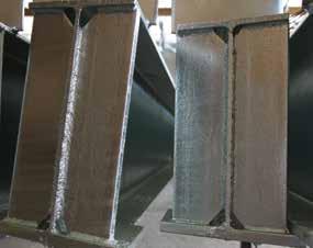
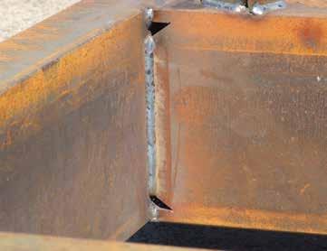
1 Requirement for Holes - Holes for Hanging In order for items to progress through the series of pretreatment and galvanizing baths at our facility, they must be suspended in a suitable manner to ensure all liquids are able to clean and galvanize all surfaces. If items are small enough, they can be out sourced and centrifuged in perforated baskets (spinning). This process is ideal for large numbers of nuts, bolts etc. Touch marks are often an issue with centrifuged items where they make contact whilst being processed. In house, some products are processed in specialized dipping frames or racks and allow large quantities of straight lengths to be galvanized at the same time. Minimal areas of the surface of each section will be in contact with parts of the dipping racks resulting in small touch marks which, subject to quantity and end use of the items, may or may not be touched up with repair paint. Large assemblies are supported by chain slings or lifting fixtures. To enable safe handling, lifting points should be incorporated into the fabrication s design distributing the weight equally over 4 points. Lifting lugs and heavy duty washers can be welded at the required points and then removed after galvanizing. These are preferable to chain or wire marks remaining after galvanizing. The coating can be repaired with appropriate zinc enriched paint if aesthetics is an issue after removing unwanted lifting points. Most general fabrications are suspended by wire on apparatus referred to as headframes and hung vertically or on an angle to maximise drainage of pre-treatment chemicals and molten zinc. Additional holes or lifting lugs may be required after fabrication to enable successful galvanizing of items. In order to understand where to place a hole for galvanizing, the function of each hole must be understood. The various functions of holes can be categorized into four requirements: hanging, prevention of pooling and entrapment, venting and draining and to relieve pressure from overlapping surfaces. Reference here-on is made to the high end (air exit point) and low end (zinc entry point). Holes for Hanging The shape and dimensions of an item will determine how it is suspended during the hot dip galvanizing process. Where possible holes located in cleats, flanges or base plates will be utilised to suspend general fabricated items. Should holes not be available, they will be required to be added to enable the item to be hung in the correct plane, allow processing liquids to drain and to minimize distortion. Hunter Galvanizing prefers external lifting lugs to be fitted to long or heavy items. General Guidelines Subject to weight; items less than 2m require a hole or lifting lug placed at one end. Longer and heavy items will require holes or lifting lugs at both ends. Holes should be a minimum of 10mm diameter, large enough for jigging wire to be passed through. Larger fabrications will require numerous wire strands to be used and hole sizes should be adjusted accordingly. Further information should be sought from Hunter Galvanizing staff regarding size and location of holes specific to each item.


2 Holes in end plates, cleats and gussets are utilised to suspend items. Wire, Chain or Other Touch Marks All items are processed either in dipping frames, held by chains or suspended by wire. Items supported in dipping frames may have small touch marks evident where they have been in contact with the frame structure. Chains are utilised for heavy items and will leave touch marks in their immediate area as will wire if required to be wrapped around an item or through hanging holes. The wire sticks to the surface of the galvanized coating as the item is withdrawn from the galvanizing bath. Touch marks or chain marks are usually completely galvanized affecting only the outer free zinc layer of the coating and therefore not a reason for rejection.
.")
3 Requirement for Holes - Holes to Prevent Entrapment In order for items to progress through the series of pretreatment and galvanizing baths at our facility, they must be suspended in a suitable manner to ensure all liquids are able to clean and galvanize all surfaces. If items are small enough, they can be out sourced and centrifuged in perforated baskets (spinning). This process is ideal for large numbers of nuts, bolts etc. Touch marks are often an issue with centrifuged items where they make contact whilst being processed. In house, some product ranges are processed in specialized dipping frames or racks and allow large quantities of straight lengths to be processed at the same time. Minimal areas of the surface of each section will be in contact with parts of the dipping racks resulting in small touch marks which, subject to quantity and end use of the items, may be touched up with repair paint. Large assemblies are supported by chain slings or lifting fixtures. To enable safe handling, lifting points should be incorporated into the fabrication s design distributing the weight equally over 4 points. Lifting lugs and heavy duty washers can be welded at the required points and then removed after galvanizing. These are preferable to chain or wire marks remaining after galvanizing. The coating can be repaired with appropriate zinc enriched paint if aesthetics is an issue after removing unwanted lifting points. General Guidelines: A hole, gap or mitre in the corners of gussets or stiffeners will assist processing products to drain. Holes through end plates or web plates will also provide suitable access for zinc and zinc ash to drain and means of air to escape. By adopting a hole in every corner principle, the majority of issues relating to draining can be eliminated and the best possible hot dip galvanized finish can be achieved. We recommend holes should not be less than 12mm in diameter, (larger if the design permits) to enable zinc and zinc ash to escape freely as items are withdrawn from the galvanizing bath. The following aesthetic issues are generally deemed acceptable under the governing standards for hot dip galvanizing. Simple allowances whilst fabricating can minimise these effects. Most general fabrications are suspended by wire on apparatus referred to as headframes and hung vertically or on an angle to maximise drainage of pre-treatment chemicals and molten zinc. Additional holes or lifting lugs may be required after fabrication to enable successful galvanizing of items. In order to understand where to place a hole for galvanizing, the function of each hole must be understood. The various functions of holes can be categorized into four requirements: hanging, prevention of pooling and entrapment, venting and draining and to relieve pressure from overlapping surfaces. Reference here-on is made to the high end (air exit point) and low end (zinc entry point). Holes to Prevent Entrapment When an item is suspended on a headframe, it remains in the same hanging position throughout the hot dip galvanizing process. Holes are required to be in the appropriate location to ensure pre-treatment acids, molten zinc and zinc ash can flow freely from all item surfaces as it is submerged and withdrawn from each processing bath.
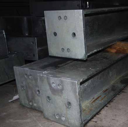
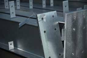
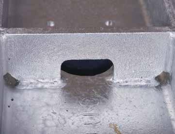
4 Recommended holes or mitres for general fabrications, universal beams and columns.

5 By placing a HOLE IN EVERY CORNER of general fabrications, most issues relating to entrapment of air, zinc and zinc ash will be minimised. Recommended location of holes, mitres or cropped corners


6 Air Locks Pre-treatment acids are critical in preparing the steel surface for galvanizing. The acids remove contaminants including surface rust, soluble oils and water based paint coatings. When an item is suspended on a headframe, air can become trapped in corners at the high points. An air pocket prevents cleaning solutions from preparing the steel surface and the zinc coating will not form in these areas. Zinc Pooling Molten zinc is very dense and solidifies immediately upon withdrawal from the galvanizing bath. Excess zinc will collect in corners of fabrications subject to the item s hanging position. Zinc pooling will increase the overall weight of an item and may affect the cost and end use application. An airlock will form if pre-treatment chemicals are unable to escape from corner areas. Zinc collects in corners of items if holes are not correctly positioned. Ash Formation Zinc ash is a bi-product of the zinc iron alloying process. Ash forms on the surface of the molten zinc and is skimmed away from items as they are withdrawn through the zinc s surface. Subject to the number of items processed in the galvanizing bath at one time, some surfaces may not be reached by operating staff and ash may adhere to the steel as it is withdrawn. A light skin or film may form in isolated areas on the surface of an item. Heavier deposits of ash may remain trapped within a fabricated item or hollow section. Upon drying the ash appears as a yellow-brown powder or in clumps. As ash is relatively pure zinc it does not represent any concern to the coating properties other than aesthetics and can be easily brushed from the surface. Light film of ash. Ash can become trapped on surfaces within structural steel sections. Ash will be caught in long lengths of hollow sections.
.")
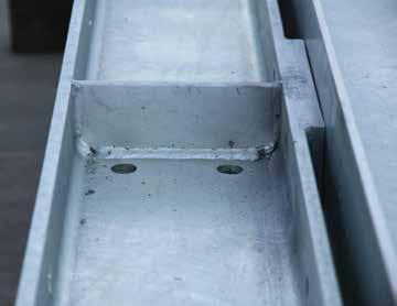
7 Requirement for Holes - Overlapping Surfaces In order for items to progress through the series of pretreatment and galvanizing baths at our facility, they must be suspended in a suitable manner to ensure all liquids are able to clean and galvanize all surfaces. If items are small enough, they can be out sourced and centrifuged in perforated baskets (spinning). This process is ideal for large numbers of nuts, bolts etc. Touch marks are often an issue with centrifuged items where they make contact whilst being processed. In house, some product ranges are processed in specialized dipping frames or racks and allow large quantities of straight lengths to be processed at the same time. Minimal areas of the surface of each section will be in contact with parts of the dipping racks resulting in small touch marks which, subject to quantity and end use of the items, may be touched up with repair paint. Large assemblies are supported by chain slings or lifting fixtures. To enable safe handling, lifting points should be incorporated into the fabrication s design distributing the weight equally over 4 points. Lifting lugs and heavy duty washers can be welded at the required points and then removed after galvanizing. These are preferable to chain or wire marks remaining after galvanizing. The coating can be repaired with appropriate zinc enriched paint if aesthetics is an issue after removing unwanted lifting points. Most general fabrications are suspended by wire on apparatus referred to as headframes and hung vertically or on an angle to maximise drainage of pre-treatment chemicals and molten zinc. Additional holes or lifting lugs may be required after fabrication to enable successful galvanizing of items. Galvanizing staff are at risk as this force may cause steel fragments or molten zinc to be blown from the galvanizing bath causing injury and rendering processing equipment inoperable. In order for items to be processed safely, holes are required to enable air and moisture to escape and pressure to be relieved. The following rules must apply regarding size and location of relief holes. General Guidelines: Overlapping areas 10cm² or greater must have one hole every 100mm. Thin, long overlapping areas require one hole every 300mm in length. Where possible avoid designing items with back to back channels and angles unless a gap of 2.5mm or greater is allowed. Overlapping areas greater than 40cm² should be avoided at all times. Holes may be placed through one or both steel surfaces and must be greater than 10mm in diameter. Alternatively, staggered welding can provide sufficient means for air to escape. In some instances, it may be suitable to leave one edge free of weld. As detailed in Welding pre-treatment chemicals become trapped between overlapping surfaces and may result in aesthetic issues. In order to understand where to place a hole for galvanizing, the function of each hole must be understood. The various functions of holes can be categorized into four requirements: hanging, prevention of pooling and entrapment, venting and draining and to relieve pressure from overlapping surfaces. Reference here-on is made to the high end (air exit point) and low end (zinc entry point). Holes for Venting Overlapping Surfaces When steel sections are welded together, air is trapped between the overlapping surfaces. At galvanizing temperatures, the entrapped air converts to super heated steam with pressure sufficient to force weak areas within a fabrication (either in steel thickness or weld) to expand, distort or tear. The overhanging edge remains free of weld to allow air to escape.


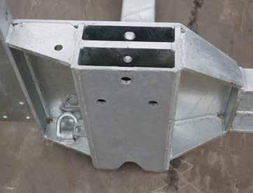
8 Overlapping areas will require suitable venting holes in place. Holes can be through one or both surfaces. Gaps should be provided between back to back channels and plates. Entrapped acid causes issues in weld pin holes and overlapping surfaces. Recommended location of holes, mitres or cropped corners
9 Requirement for Holes - Holes for Hollow Sections In order for items to progress through the series of pretreatment and galvanizing baths at our facility, they must be suspended in a suitable manner to ensure all liquids are able to clean and galvanize all surfaces. If items are small enough, they can be out sourced and centrifuged in perforated baskets (spinning). This process is ideal for large numbers of nuts, bolts etc. Touch marks are often an issue with centrifuged items where they make contact whilst being processed. In house, some product ranges are processed in specialized dipping frames or racks and allow large quantities of straight lengths to be processed at the same time. Minimal areas of the surface of each section will be in contact with parts of the dipping racks resulting in small touch marks which, subject to quantity and end use of the items, may be touched up with repair paint. Large assemblies are supported by chain slings or lifting fixtures. To enable safe handling, lifting points should be incorporated into the fabrication s design distributing the weight equally over 4 points. Lifting lugs and heavy duty washers can be welded at the required points and then removed after galvanizing. These are preferable to chain or wire marks remaining after galvanizing. The coating can be repaired with appropriate zinc enriched paint if aesthetics is an issue after removing unwanted lifting points. Most general fabrications are suspended by wire on apparatus referred to as headframes and hung vertically or on an angle to maximise drainage of pre-treatment chemicals and molten zinc. Additional holes or lifting lugs may be required after fabrication to enable successful galvanizing of items. In order to understand where to place a hole for galvanizing, the function of each hole must be understood. The various functions of holes can be categorized into four requirements: hanging, prevention of pooling and entrapment, venting and draining and to relieve pressure from overlapping surfaces. Sealed hollow sections will float on the surface until such time they are either pushed or dragged below the zinc s surface. As discussed in Holes for Venting Overlapping Surfaces; at galvanizing temperatures trapped air or moisture will very quickly convert to super heated steam. The resultant pressure can expand, distort or tear weaker areas within a fabrication (either in steel thickness or weld) with explosive force. Galvanizing staff are at risk as this force may cause steel fragments or molten zinc to be blown from the galvanizing bath causing injury and rendering processing equipment inoperable. In order for items to be processed safely, vent holes are required to enable the item to be submerged and allow air and moisture to escape at the same rate as the zinc enters. The following rules must apply regarding size and location of holes for hollow sections to permit hot dip galvanizing in a controlled and safe manner. General Guidelines: All capped hollow sections must have a minimum of one hole or cropped corner diagonally placed at each end to permit zinc entry at the low end and air escape at the high end when suspended on a headframe. Hollow sections open one end (low end) require a minimum of one hole or cropped corner at the capped end (high end). Hollow sections welded within a fabrication must have holes placed at both ends of each hollow section. Holes or cropped areas should be as large as the design or end use will allow for expanding air, processing liquids, zinc and zinc ash to escape from within. The total area of holes must be equal to or no less than 25% of the diameter of cross section of the hollow piece. Numerous holes can be placed in order to meet this venting requirement. Holes less than 10mm are not functional as they can easily become blocked; Hunter Galvanizing recommends 12mm diameter holes minimum. Reference here-on is made to the high end (air exit point) and low end (zinc entry point). Holes for Venting & Draining Hollow Sections Molten zinc is extremely dense. Consideration of venting and draining requirements is mandatory when fabricating items for hot dip galvanizing to eliminate potential hazards: items may float on top of the molten zinc air may become trapped or is slow to escape


10 Holes must be located in diagonally opposite corners of SHS and RHS. Holes or V notches must be present in all hollow sections within a fabrication. The overall dimensions of an item and hanging method must be considered when fabricating items which include hollow sections. Small holes may result in floating or drainage issues. Holes should be as large as possible to facilitate ease of galvanizing and to allow the best possible coating to be achieved.


11 External Holes SHS, RHS, CHS & Pipe Sections In open-ended SHS, RHS and pipe sections, a hanging hole each end is required to allow hanging wire to pass through. If the hollow section is capped, additional holes for venting are required. For SHS and RHS sections, holes should be placed in the corners. In pipe sections holes are required to be as close to the outside diameter as possible. Holes placed in the centre of end caps will allow air pockets to form or zinc to pool. The minimum acceptable number of venting holes is one each end placed diagonally opposite. If there are no means of holding the item two holes each end are required, with holes located diagonally opposite each other. The size of the venting holes is critical for processing hollow sections. Sufficient air must escape at the same rate zinc is entering the section. Holes should be no less than 25% of the cross section of the hollow section. *The minimum hole size acceptable on any item is 10mm, however as holes this size can prove ineffective we recommend holes sizes of 12mm or greater. Examples A section of 100 x 100 SHS or 100 x 50 RHS must have holes at each end equivalent to approximately 25mm either as: 1 x 25mm hole each end OR 2 x 12mm holes each end OR 4 x 6mm holes each end A section of 50mm diameter pipe must have holes at each end equivalent to approximately 12mm either as: 1 x 12mm hole each end OR 2 x 10mm* holes each end Fabricated items, gates, handrails and fencing require thought regarding placement of holes. Ideally holes should be placed externally to allow quick visual inspection by the galvanizer. Unwanted holes can later be filled with epoxy filler, lead or threaded plugs. Preferred Option No end plate Preferred Option No end plate Correct Holes Holes for hanging Holes for hanging
 to eliminate air pockets and zinc pooling inside the fabrication.")


12 Internal Holes SHS, RHS, CHS & Pipe Sections Where internal holes are utilised, sections should be interconnected using mitred joints or interconnecting holes. Internal holes should be as close as possible in size to the cross section of the hollow section (minimum of 50%) to eliminate air pockets and zinc pooling inside the fabrication. Internal holes are not recommended due to inherent safety concerns. Hunter Galvanizing requires signed documentation to guarantee holes have been correctly placed. Air and zinc must flow freely within the hollow sections. 1. External Holes 2. Internal Holes 3. Mandatory - Holes in Bends 4. Mandatory - Ends Remain Open Holes for Venting Tanks and Hollow Vessels Specific attention to venting and draining is required when preparing large hollow items such as tanks, pods or vessels for galvanizing. The design of tanks and closed vessels must allow for pre-treatment chemicals, air and zinc to enter, fill and flow out of the enclosed space. A large filling hole (minimum of 50mm diameter for each 0.5 cubic metres) is required at the low end when suspended for galvanizing. A vent hole of equal dimensions will be needed diagonally opposite the filling hole to allow air to escape. Internal baffles in tanks must have their corners cropped prior to installation or with large drainage holes to permit free flow of the air and zinc within. Access ports, bosses and openings should be finished flush inside and should be positioned so that all processing fluids can be drained out during the galvanizing process. Whilst processing tanks, a large volume of zinc will pass through the vessel. As a safety precaution, we require heavy duty lifting lugs attached to each item. We recommend discussing this requirement with Hunter Galvanizing staff prior to fabrication. General Guidelines Venting holes are required to be diametrically opposite. Minimum acceptable hole size is 50mm in diameter. Subject to tank size additional holes may be required. Internal baffles should be cropped top and bottom. Lifting lugs will be required to facilitate handling. Design should incorporate an inspection hole to enable internal surfaces to be viewed. Vent Drain Internal baffles of tanks must be cropped
Design Guide for Hot Dip Galvanizing best practice for venting and draining
 Design Guide for Hot Dip Galvanizing best practice for venting and draining Contents Introduction 3 Handrails/ 25 Balustrades Importance 4 of Venting and Draining Purpose Safety Quality Aesthetics General
Hot Dip Galvanizing by Perry Metal Protection
 Hot Dip Galvanizing by Perry Metal Protection DESIGN PRINCIPLES It s simple to specify and more cost effective than alternative coating systems. COMMERICAL INDUSTRIAL INFRASTRUCTURE RESIDENTIAL We ve got
for a manual for steel detailers, engineers & fabricators, containing working drawings & details for hot-dip galvanized structures
 for a manual for steel detailers, engineers & fabricators, containing working drawings & details for hot-dip galvanized structures l b Ta f o e s t en t n Co Recommended Details for Hot-Dip Galvanized
Basket & Screen Data. Cylindrical baskets for simplex and duplex strainers up to 8" size
 Basket & Screen Data Cylindrical baskets for simplex and duplex strainers up to 8" size Slant top baskets for Model 510 simplex and Model 570 duplex strainers sizes 8" to 36" Basket and Screen Design The
Installing Gates and Posts Tips and Pointers
 Installing Gates and Posts Tips and Pointers When one installs a gate we hope that the gate will not sag and that the gate post will not move so that our work will not only look great but function properly.
wellington french patio doorset fitting & fixing guidelines
 wellington french patio doorset fitting & fixing guidelines CAUTION SAFETY: Large windows and glass units are heavy and may be hazardous. Great care MUST be taken to avoid injury during manual handling
ISO INTERNATIONAL STANDARD. Fasteners Hot dip galvanized coatings. Éléments de fixation Revêtements de galvanisation à chaud
 Provläsningsexemplar / Preview INTERNATIONAL STANDARD ISO 10684 First edition 2004-07-15 Fasteners Hot dip galvanized coatings Éléments de fixation Revêtements de galvanisation à chaud Reference number
APPENDIX FENCE GENERAL NOTES
 APPENDIX FENCE GENERAL NOTES 1. Fabric: 9 gage, 2" mesh, knuckle top and bottom, placed on the outside of posts, single fabric width for the entire height. 2. All fencing to be standard galvanized finish.
TENANT IMPROVEMENT 16 FEBRUARY WEST 27TH STREET, 4TH FLOOR 100% CD OWNER/BID ADD 1-03/08/2018
 SECTION 055000 - PART 1 - GENERAL 1.1 RELATED DOCUMENTS A. Drawings and general provisions of the Contract, including General and Supplementary Conditions and Division 01 Specification Sections, apply
Kestrel Aluminium Systems Limited. Product Manual Section 11 Thermal Framing System - Fabrication. Manual Version
 Limited Product Manual Section 11 - Fabrication Manual Version 23.0.1 Section 11.01 Fabrication 11.01.01 sheet 1 General guidelines for cutting and bar preparation Section 11 Contents Section 11.02 Fabrication
OPERATING MANUAL SHOCK TOOL OWS WENZEL DOWNHOLE TOOLS LTD.
 OPERATING MANUAL SHOCK TOOL OWS WENZEL DOWNHOLE TOOLS LTD. Release Notes: Release 2 Issued May 2016 Document # OM ST 001, Shock Tool Operating Manual Reviewed By: RG 1 P age OPERATING MANUAL SHOCK TOOL
Architecturally Exposed Structural Steelwork (AESS) Code of Practice (for Fabricators)
 Code of Practice (for Fabricators)") Architecturally Exposed Structural Steelwork (AESS) Code of Practice (for Fabricators) Code of Practice (for Fabricators) Architecturally Exposed Structural Steel (AESS) 1.1 SCOPE AND REQUIREMENTS 1.1.1
Architecturally Exposed Structural Steelwork (AESS) Code of Practice (for Fabricators) Code of Practice (for Fabricators) Architecturally Exposed Structural Steel (AESS) 1.1 SCOPE AND REQUIREMENTS 1.1.1
Contents. Technical Metal Industrial Co. L.L.C.
 We, at Technical Metal Industrial Co. L.L.C. take pride in declaring the company s commitment to satisfy our customers by providing high quality products and promptly delivering them as per the agreed
SECTION METAL FABRICATIONS
 SECTION 05100 PART 1 - GENERAL 1.01 DESCRIPTION A. Section includes specifications for metal fabrications, including minimum requirements for fabricator, and galvanizing. 1.02 REFERENCE STANDARDS A. ASTM
Runcorn: A Project First for Europe
 Page1 Runcorn: A Project First for Europe A Combination of Film-Galvanising and Hot-Dip Galvanising This is an interesting look at the first project in Europe to use both film-galvanising and hot-dip galvanising
FINNEY7 SR 5500G TENDER IN ORIGINAL CONDITION
 IN ORIGINAL CONDITION Fig 1. Original Appearance Side raves Sanding gear TIA Water treatment system 5500G - 3 5500G TENDER IN REBUILT CONDITION Fig 2. Rebuilt Condition Cut down side raves with fire iron
Manufacturing: Chapter 3 Casting
 CHAPTER THREE Metal Casting Casting, shown in Fig. 3.1, is the process of pouring molten metal into a mould containing a cavity, which represents the required product shape. It is one of the most commonly
ISO INTERNATIONAL STANDARD. Fasteners Hot dip galvanized coatings. Éléments de fixation Revêtements de galvanisation à chaud
 INTERNATIONAL STANDARD ISO 10684 First edition 2004-07-15 Fasteners Hot dip galvanized coatings Éléments de fixation Revêtements de galvanisation à chaud Reference number ISO 10684:2004(E) ISO 2004 PDF
SPACER APPLICATION: KEY POİNTS FOR HİGH QUALİTY İG UNİTS
 SPACER APPLICATION: KEY POİNTS FOR HİGH QUALİTY İG UNİTS Application of spacer should be in clean and indoor area. Glass washing machine, hot press machine and spacer application table should be in the
Annie Tel: MSN: All chain-link fences aren't the same
 Attractive, versatile and creative - a chain-link fence system can be an excellent choice. With the right fence you can expect years of protection, privacy and value. But as with any investment, it pays
SYW Industry Sdn. Bhd. Stud Anchor. Hexagon Nut / Flange Nut. U - Bolt (c/w 2 Nuts) Steel Band. 1 of 8
 Steel Band. 1 of 8") SYW Industry Sdn. Bhd. Stud Anchor Hexagon Nut / Flange Nut U - Bolt (c/w 2 Nuts) Steel Band 1 of 8 BT Anchor (MM size) Expansion Anchor 2 of 8 Set Anchor Sleeve Anchor with Flange Nut 3 of 8 BT Anchor
SYW Industry Sdn. Bhd. Stud Anchor Hexagon Nut / Flange Nut U - Bolt (c/w 2 Nuts) Steel Band 1 of 8 BT Anchor (MM size) Expansion Anchor 2 of 8 Set Anchor Sleeve Anchor with Flange Nut 3 of 8 BT Anchor
joining materials - wood
 UNIT D E S I G N A N D M A N U F A C T U R E : C O U R S E M A T E R I A L Wood joints joining materials - wood The majority of joints used in woodcraft have been designed specifically to attain the maximum
Operating, Servicing, and Safety Manual Model # 100 Standard Hydraulic Tubing Notcher Model #100-U Heavy Duty Hydraulic Tubing Notcher
 Operating, Servicing, and Safety Manual Model # 100 Standard Hydraulic Tubing Notcher Model #100-U Heavy Duty Hydraulic Tubing Notcher Model # 100 Standard Model #100-U Heavy Duty CAUTION: Read and Understand
KO LO SH E LT E R. High Capacity and Flexibility
 KO LO SH E LT E R High Capacity and Flexibility The unique styling of our redesigned Dero Kolo Shelter will help beautify your facility and provide secure, covered bike parking for cyclists. The Kolo is
FINNEY7 4500G May17 SR 4500G TENDER. Fig 1. Original Appearance. Side raves Sanding gear Front water fillers TIA Water treatment system
 Fig 1. Original Appearance Side raves Sanding gear Front water fillers TIA Water treatment system 4500G - 3 Fig 2. Rebuilt Condition Cut down side raves with fire iron tunnels# TIA removed and replaced
FLOOR ANCHOR SYSTEM APPLICATIONS L TRACK APPLICATIONS
 FLOOR ANCHOR SYSTEM APPLICATIONS Sure-Lok recommends the following for floor anchor system layout and installation. These recommendations are not all-inclusive and may not be applicable to every system
UP139 CRUISE-A-LONG (STANDARD) NATURAL COATED DECK COATED RAMP DESCRIPTION SQUIRREL PANEL BACK WALL CLEAR BUBBLE CRUISE RAIL SQUARE SPIRAL WHEEL 90 AN
 NATURAL COATED DECK COATED RAMP DESCRIPTION SQUIRREL PANEL BACK WALL CLEAR BUBBLE CRUISE RAIL SQUARE SPIRAL WHEEL 90 AN") UP39 CRUISE-A-LONG (STANDARD) NATURAL COATED DECK COATED RAMP DESCRIPTION SQUIRREL PANEL BACK WALL CLEAR BUBBLE CRUISE RAIL SQUARE SPIRAL WHEEL 90 ANGLE BRACKET TUBE BRACKET TUBE WARNING LABEL PLATE HARDWARE
UP39 CRUISE-A-LONG (STANDARD) NATURAL COATED DECK COATED RAMP DESCRIPTION SQUIRREL PANEL BACK WALL CLEAR BUBBLE CRUISE RAIL SQUARE SPIRAL WHEEL 90 ANGLE BRACKET TUBE BRACKET TUBE WARNING LABEL PLATE HARDWARE
INSTRUMENT MOUNTING STANDS PRODUCT CATALOG Continuous Tray Support System for Instrumentation and Controls
 INSTRUMENT MOUNTING STANDS PRODUCT CATALOG Continuous Tray Support System for Instrumentation and Controls James C. White Company, Inc. Greenville, SC PAGE 5 Standard Instrument Stands SINGLE WALL STAND
5/16" Flange nut. Bolt Keeper Plate (8" Sq. SYS.) (3) 1/2" x 3" Hex head connector zinc plated bolt w/ washers and nut. Anchor 3" sq. 7 Ga.
 (3) 1/2 x 3 Hex head connector zinc plated bolt w/ washers and nut. Anchor 3 sq. 7 Ga.") 2 1/2" x 2 1/2" x 10 Ga. 6" 5" 4" Variable Slipbase (8" Sq. SYS.) 5/16 Corner Bolt W/ nut 5/16" Flange nut Stub Insert (8" Sq. SYS.) Bolt Keeper Plate (8" Sq. SYS.) (3) 1/2" x 3" Hex head connector zinc
2 1/2" x 2 1/2" x 10 Ga. 6" 5" 4" Variable Slipbase (8" Sq. SYS.) 5/16 Corner Bolt W/ nut 5/16" Flange nut Stub Insert (8" Sq. SYS.) Bolt Keeper Plate (8" Sq. SYS.) (3) 1/2" x 3" Hex head connector zinc
STEEL PIPE GUIDERAIL 01/01/
 NOTES PIPE RAILING & POSTS: Pipe Rails and s shall be in accordance with ASTM A5 Grade B for standard weight pipe and ASTM A500 Grade B, C or D or ASTM A50 for structural tube. Bars for handrail supports
Dura-Lock Roof System
 DLR-14 Dura-Lock Roof System Assembly and Installation Instructions Read the instructions before starting the job. They explain the steps required to produce a finished product that will meet factory specifications.
Operating instructions OI/FPD350-EN Rev. H. FPD350 Torbar Averaging pitot tubes
 Operating instructions OI/FPD350-EN Rev. H FPD350 Torbar The Company We are an established world force in the design and manufacture of measurement products for industrial process control, flow measurement,
INSTRUCTION MANUAL. Force Transducer Output Tube Repair Kit
 INSTRUCTION MANUAL Model 400-TR Force Transducer Output Tube Repair Kit June 4, 2004, Revision 5 Copyright 2004 Aurora Scientific Inc. Aurora Scientific Inc. 360 Industrial Pkwy. S., Unit 4 Aurora, Ontario,
Tel: +44 (0)
") 4 Lindapter s support fixing range offers a series of ideal solutions for all building services. This includes the suspension of HVAC equipment, pipe work, fire protection/sprinkler systems, suspended
4 Lindapter s support fixing range offers a series of ideal solutions for all building services. This includes the suspension of HVAC equipment, pipe work, fire protection/sprinkler systems, suspended
ALUMINUM PIPE GUIDERAIL 01/01/
 NOTES PIPE RAILING & POSTS: Structural Tube, Pipe and Bar shall be in accordance with ASTM B22 or ASTM B429, Alloy 606-T6. End Rail 90 bends and corner bends with maximum 4-0" post spacing, may be Alloy
UP133 CRAWL & TODDLE (STANDARD) NATURAL COATED DECK COATED RAMP FRONT WALL BACK WALL DESCRIPTION COATED STEPS 90 ANGLE BRACKET LEFT WALL RIGHT WALL CL
 NATURAL COATED DECK COATED RAMP FRONT WALL BACK WALL DESCRIPTION COATED STEPS 90 ANGLE BRACKET LEFT WALL RIGHT WALL CL") UP33 CRAWL & TODDLE (STANDARD) NATURAL COATED DECK COATED RAMP FRONT WALL BACK WALL DESCRIPTION COATED STEPS 90 ANGLE BRACKET LEFT WALL RIGHT WALL CLEAR BUBBLE CRUISE RAIL SQUARE SPIRAL WHEEL TRIANGLE
UP33 CRAWL & TODDLE (STANDARD) NATURAL COATED DECK COATED RAMP FRONT WALL BACK WALL DESCRIPTION COATED STEPS 90 ANGLE BRACKET LEFT WALL RIGHT WALL CLEAR BUBBLE CRUISE RAIL SQUARE SPIRAL WHEEL TRIANGLE
TYPE J (20 FT - 40 FT) MICHIGAN DEPARTMENT OF TRANSPORTATION 10-0" 7-6" NOTE: sheet 5 & 6 of 10) DEPARTMENT DIRECTOR. Kirk T.
 MICHIGAN DEPARTMENT OF TRANSPORTATION 10-0 7-6 NOTE: sheet 5 & 6 of 10) DEPARTMENT DIRECTOR. Kirk T.") Column truss connection Chord splice (see details (See details sheets 3 & 4 of 10) s Top truss chord Free end panel 10-0" Support end panels length varies (See chart below) \ Truss Back truss chord Top
Column truss connection Chord splice (see details (See details sheets 3 & 4 of 10) s Top truss chord Free end panel 10-0" Support end panels length varies (See chart below) \ Truss Back truss chord Top
 UP4 LEARN-A-LOT (PLAYFUL) Parts List DESCRIPTION 90 ANGLE BRACKET DOOR WINDOW MUSIC CATERPILLAR CIRCLE FRAME CIRCLE MIRROR YELLOW STAINED GLASS RED STAINED GLASS SQUARE TRIANGLE SPIRAL WHEEL SQUARE MIRROR
(50 FT FT) MICHIGAN DEPARTMENT OF TRANSPORTATION 10-0" 7-6" 8-0" 6-0" Truss Depth. 3" sheets 5 & 6 of 10) DEPARTMENT DIRECTOR. Kirk T.
 MICHIGAN DEPARTMENT OF TRANSPORTATION 10-0 7-6 8-0 6-0 Truss Depth. 3 sheets 5 & 6 of 10) DEPARTMENT DIRECTOR. Kirk T.") Column truss connection (See details sheets 3 & 4 of 10) \ Span (Odd number of panels) \ Span (Even number of panels) Back truss chord Top truss chord \ Truss Chord splice Truss depth (See details \ Left
Column truss connection (See details sheets 3 & 4 of 10) \ Span (Odd number of panels) \ Span (Even number of panels) Back truss chord Top truss chord \ Truss Chord splice Truss depth (See details \ Left
 UP43 LEARN-A-L0T (NATURAL) Parts List DESCRIPTION 90 ANGLE BRACKET DOOR WINDOW MUSIC CATERPILLAR CIRCLE FRAME CIRCLE MIRROR YELLOW STAINED GLASS RED STAINED GLASS SQUARE TRIANGLE SPIRAL WHEEL SQUARE MIRROR
CHAPTER5 5 ZERO DEFECT MANUFACTURING IN THE PRODUCTION OF IMPELLER THROUGH THE APPLICATION OF CAD / CAE
 33 CHAPTER5 5 ZERO DEFECT MANUFACTURING IN THE PRODUCTION OF IMPELLER THROUGH THE APPLICATION OF CAD / CAE 5.1 INTRODUCTION In the first place of research, CAD/CAE was applied to achieve ZERO DEFECT MANUFACTURING
Tool 3-1 A2 Bushing 6 Check if the bushing supports (angle iron) are properly welded with the upper part of the structure pipes. welded bushing suppor
 are properly welded with the upper part of the structure pipes. welded bushing suppor") Rope Pump MANUFACTURING checklist for quality control A Welding General 1 Check if welding jigs are used for welding of the main parts (wheel, structure frame and bushings) 2 Check if the pump parts are
Rope Pump MANUFACTURING checklist for quality control A Welding General 1 Check if welding jigs are used for welding of the main parts (wheel, structure frame and bushings) 2 Check if the pump parts are
MANUFACTURING INC. Specifications
 Page 1 of 4 GENERAL 11 Aluminum security screen doors must be tested by a recognized testing laboratory to conform to SMA 6001-2002 Proposed American National Standard Specifications for Metal Protection
PENSTOCK VALVES. Performance through Excellence
 VALVES & MANUFACTURING (1988) LTD. PENSTOCK VALVES Performance through Excellence SLIDEGATES WEIR GATES STOP LOGS SLIDEGATES PRECISION FACE SEALING VALVES WEIR GATES STOP LOGS SLIDEGATES Actuation Installation
Students will learn to correctly prepare, assemble, and solvent weld ABS piping.
 Description Students will learn to correctly prepare, assemble, and solvent weld ABS piping. Lesson Outcomes The student will be able to: Accurately cut plastic piping Prepare plastic piping for solvent
CITY OF PITTSBURG ENGINEERING DEPARTMENT CONTRACT NO A WATER TREATEMENT PLANT CAPITAL IMPROVEMENTS PHASE 1A ADDENDUM #1 FENCE AND DITCH AUGUST
 CITY OF PITTSBURG ENGINEERING DEPARTMENT CONTRACT NO. 2012-16A WATER TREATEMENT PLANT CAPITAL IMPROVEMENTS PHASE 1A ADDENDUM #1 FENCE AND DITCH AUGUST 2014 CHAIN LINK FENCE SPECIFICATIONS Chain link fence,
Connection Solutions for Wood-frame Structures. Copyright Materials. Learning Objectives
 Connection Solutions for Wood-frame Structures Presented by: John Buddy Showalter, P.E. Vice President, Technology Transfer The Wood Products Council is a Registered Provider with. Credit(s) earned on
2009 MODEL ASSEMBLY, INSTALLATION AND MAINTENANCE INSTRUCTIONS
 2009 MODEL ASSEMBLY, INSTALLATION AND MAINTENANCE INSTRUCTIONS It is important that these instructions are adhered to in their entirety. Please read the instructions fully before starting installation
.1 Comply with the General Conditions of the Contract, Supplementary General Conditions and the requirements of Division 1.
 PAGE 1 PART 1 GENERAL 1.1 REFERENCE.1 Comply with the General Conditions of the Contract, Supplementary General Conditions and the requirements of Division 1. 1.2 RELATED WORK SPECIFIED ELSEWHERE.1 Installation
Spiral Slide
 IMPORTANT Page 1 PLEASE READ THESE INSTRUCTIONS BEFORE COMMENCING ASSEMBLY. All equipment must be installed in accordance with these instructions. Check your shipment against Bill of Lading and Parts list.
Quick-Drain Installation Requirements Large Volume Drainage Models
 Quick-Drain Installation Requirements Large Volume Drainage Models Installation of the Quick-Drain-QFLV and Quick-Drain-HFLV Fluid Management Systems is a straightforward process. These installation instructions
Copyright Notice. HCL Technologies Ltd. All rights reserved. A DEFINITIVE GUIDE TO DESIGN FOR MANUFACTURING SUCCESS
 Copyright Notice HCL Technologies Ltd. All rights reserved. No part of this document (whether in hardcopy or electronic form) may be reproduced, stored in a retrieval system, or transmitted, in any form
Storing, Handling, and Cutting Steel Panels
 Storing, Handling, and Cutting Steel s Storing Specifically check your quantities, colors, and lengths All materials should be used as soon as possible Steel bundles should be stored indoors with enough
LOCKER SPECIFIERS GUIDE. The standard of excellence for business, industry and institutions. Lockers Cabinets Shelving
 LOCKER SPECIFIERS GUIDE Lockers Cabinets Shelving The standard of excellence for business, industry and institutions FINISH GUIDE NANO METAL ROLLER LATCHING SYSTEM For unmatched security, nano metal roller
SCI-FAB Product Specifications. Casework Section 1. Part 1 General
 SCI-FAB Product Specifications Casework Section 1 Part 1 General 1.1 SCOPE OF WORK Includes all factory fabricated stainless steel casework as required by the project drawings. 1.2 TYPICAL INCLUSIONS A.
INSTRUCTIONS FOR AIRFLEX 36WCBEP/36WCSEP WEAR PLATE REPLACEMENT USING GASKET SEALING TAPE
 INSTRUCTIONS FOR AIRFLEX 36WCBEP/36WCSEP WEAR PLATE REPLACEMENT USING GASKET SEALING TAPE The material included in this kit is to be used for WC styles of brakes that are designed or upgraded to the EP
Salter Industries Spiral Stair
 Salter Industries Spiral Stair The Leader in Spiral Staircases Continuous Sleeve Stair Installation Instructions TOOLS NEEDED: 1. Electric drill with hex chuck and Phillips bit 2. Drill bits 1/8", 1/4",
A representative from Occupational Health is to be involved in the commissioning process to address any Respiratory Protection Program requirements.
 SPEC-3017 1/8 1.0 PURPOSE This specification describes the minimum requirements for the installation of breathing air distribution systems (indoor and outdoor) up to the connection to the breathing air
ISSUE MODIF. ORDER NO. WEEK ISSUE MODIF. ORDER NO. WEEK ISSUE MODIF. ORDER NO. WEEK 01 SME SME SME
 1. Summary The still pipe used with Rosemount 5900 LPG/LNG antenna is not supplied by RTR, but is to be manufactured by the customer according to the RTR drawing D9240041-910 or D7000001-466. Additional
The Wood Products Council is a Registered Provider with. . Credit(s) earned on completion of this program will be
 earned on completion of this program will be") Connection Solutions for Wood-frame Structures Presented by: John Buddy Showalter, P.E. Vice President, Technology Transfer The Wood Products Council is a Registered Provider with. Credit(s) earned on
Connection Solutions for Wood-frame Structures Presented by: John Buddy Showalter, P.E. Vice President, Technology Transfer The Wood Products Council is a Registered Provider with. Credit(s) earned on
 Page 1 of 12 Second Revision No. 5-NFPA 12-2014 [ Section No. 2.3.4 ] 2.3.4 ASTM Publications. ASTM International, 100 Barr Harbor Drive, P.O. Box C 700, West Conshohocken, PA 19428-2959. ASTM A53, Standard
Testing. Material testing will be according to applicable AASHTO, ASTM or Department methods as specified.
 907.01 Section 907. FENCING MATERIALS 907.01 General Requirements. Materials for use in fencing property, right-of-way and other installations must comply with this section. 907.02 Testing. Material testing
Chapter 1 Sand Casting Processes
 Chapter 1 Sand Casting Processes Sand casting is a mold based net shape manufacturing process in which metal parts are molded by pouring molten metal into a cavity. The mold cavity is created by withdrawing
Liner Replacement (Stainless Steel Internal Components)
") Page 1 of 15 WARNING The stainless steel edges, especially around the propeller cylinder, are very sharp. Use extreme caution when working in and around the front housing. WARNING Be sure to disconnect
Page 1 of 15 WARNING The stainless steel edges, especially around the propeller cylinder, are very sharp. Use extreme caution when working in and around the front housing. WARNING Be sure to disconnect
TECHNICAL MANUAL. OPTIMAJOINT Free Movement Joint. Free Movement Joint System for Heavy Traffic
 TECHNICAL MANUAL OPTIMAJOINT Free Movement Joint Free Movement Joint System for Heavy Traffic Version: PEIKKO GROUP 12/2018 OPTIMAJOINT Free Movement Joint Free Movement Joint System for heavy traffic
TYPE 3740XL EXTRA LARGE WET RUNNING CARTRIDGE SPLIT SEAL
 1 Foreword These instructions are provided to familiarize the user with the seal and its designated use. The instructions must be read and applied whenever work is done on the seal, and must be kept available
Khathij Industrial Fasteners
 Dear Sir/Madam, Khathij Industrial Fasteners This is Saqubar Sadique representing 'KHATHIJ INDUSTRIAL FASTENERS' from Chennai, India. We 'Khathij industrial fasteners' like to introduce us as a Stockist
International Organization for Standardization. American National Standards Institute
 DFTG1329 Standards are published documents that set up rules, specifications and protocols designed to ensure consistency, compatibility and reliability of products, materials and services. Standards are
Hex Head Bolt Set N - Includes lock nut. Used to connect male and female T connectors. Galvanized. 3/4" x 3-1/2". Standard Grade (f) Part #24279
 Part #24279") a Standard Grade (3/16 ) and Commercial Grade(1/4 ) Tie Down Is designed for use with 1-1/2" thick lumber (minimum width 6"). All hardware is mounted with 3/8" carriage bolts. All male and female dock
a Standard Grade (3/16 ) and Commercial Grade(1/4 ) Tie Down Is designed for use with 1-1/2" thick lumber (minimum width 6"). All hardware is mounted with 3/8" carriage bolts. All male and female dock
This specification describes the minimum requirements for piping systems for the following service:
 SPEC-3501 1/ 1.0 APPLICATION This specification describes the minimum requirements for piping systems for the following service: Instrument Air Design Conditions 150 PSIG @ 180 F Operating Conditions 125
Factory Assistance: Phone: Fax: Page 1
 CABLE RUNWAY ACCESSORIES Radius Drop / Stringer Drop Provides 3 bend radius Radius drop fits 6, 12 and 18 runway made from 1-1/2 x 3/8 tubing Steel construction Includes (3) cable spools, (1) bolt, (1)
Trade of Metal Fabrication. Module 5: Pipe Fabrication Unit 3: Flanges Phase 2
 Trade of Metal Fabrication Module 5: Pipe Fabrication Unit 3: Flanges Phase 2 Table of Contents List of Figures... 4 List of Tables... 5 Document Release History... 6 Module 5 Pipe Fabrication... 7 Unit
INSTALLATION MANUAL Sluice Gates, Stop-logs & Screens
 INSTALLATION MANUAL Sluice Gates, Stop-logs & Screens INTRODUCTION During manufacture and assembly of equipment great care is taken to ensure accuracy in mating the sealing faces on frame and doors, especially
CABLE TRAYS & STRUTS CATALOUGE
 CABLE TRAYS & STRUTS CATALOUGE We are the Manufacturer for Copper Bonded Ground Rod and Contract Manufacturing Company for other products made from Brass, Copper, Gunmetal, Bronze, Cast Iron, Malleable
COMPONENTS INSTALLATION
 PIPE BRACE ASSEMBLY - 8' FIXED-KNOT FENCE Brace posts... 14'x 2 7/8" Structural Tubing Cross Members... 10'x 2 3/8 Structural Tubing Angle Brace... 12'x 2 3/8 Structural Tubing Angle Brace Foot... 6' x
Pneumatic Clamp Carrier. Installation & Operation Manual
 Pneumatic Clamp Carrier Installation & Operation Manual Pneumatic Clamp Carrier Installation & Operation Manual Quick Machinery Company 8272 Peninsula Drive Kelseyville, CA 95451 phone: (707) 272-6719
Essex County College - West Essex Campus Addition And Renovations dlb # / SECTION EXPANSION FITTINGS AND LOOPS FOR HVAC PIPING
 SECTION 230516 - EXPANSION FITTINGS AND LOOPS FOR HVAC PIPING PART I - GENERAL 1.1 RELATED DOCUMENTS A. Drawings and general provisions of the Contract, including General and Supplementary Conditions and
INSPECTION. of hot-dip galvanized. steel products
 INSPECTION of hot-dip galvanized steel products 02 AMERICAN GALVANIZERS ASSOCIATION TABLE OF CONTENTS PURPOSE OF INSPECTION.................................. 4 TYPES OF INSPECTION COATING MEASUREMENT.................................
TYPE 3740/3740D WET/DRY RUNNING CARTRIDGE SPLIT SEAL
 1 Foreword These instructions are provided to familiarize the user with the seal and its designated use. The instructions must be read and applied whenever work is done on the seal, and must be kept available
This specification describes the minimum requirements for piping systems for the following service:
 201/01/13 1/ 1.0 APPLICATION This specification describes the minimum requirements for piping systems for the following service: Service Air Design Conditions Operating Conditions Blast Air (see Note 1)
Hydraulic Clamp Carrier. Installation & Operation Manual
 Hydraulic Clamp Carrier Installation & Operation Manual Hydraulic Clamp Carrier Installation & Operation Manual Quick Machinery Company 8272 Peninsula Drive Kelseyville, CA 95451 phone: (707) 272-6719
T A G PIPE ALIGNMENT CLAMPS PIPE EQUIPMENT SPECIALISTS LTD WB ALLOY WELDING PRODUCTS LTD WB ALLOY WELDING PRODUCTS LTD
 WB ALLOY WELDING PRODUCTS LTD T A G PIPE EQUIPMENT SPECIALISTS LTD PIPE ALIGNMENT CLAMPS WB ALLOY WELDING PRODUCTS LTD E-Z FIT RED Pipe welding clamp 1-12 o/d Quick and E-Z to use Rugged frame, built for
Installation Guide. Capped Cellular PVC Fencing. Table of Contents. Storage and Handling Tools Needed Fence Layout and Locating Posts
 Capped Cellular PVC Fencing Installation Guide Table of Contents Storage and Handling Tools Needed Fence Layout and Locating Posts Installation instructions 4 x 4 Over Sleeve Post - 3.5 Rail Privacy Shadowbox
INSTALLATION MANUAL H A
 INSTALLATION MANUAL CABINET RACK CR-43-6 (4-UNIT SIZE) Be sure to read this installation manual thoroughly before installing this Cabinet Rack. For the mounting procedures of the components and the relevant
MATERIAL COMBINATION NUMBER 2: Corrosive environment requiring harder, wear-resistant seating faces and resistance to dezincification.
 Cast Iron Slide Gates Spec Sheet General The contractor shall furnish and install the following cast iron slide gate assemblies as listed on the Gate Schedule and detailed on the manufacturer s drawings.
Fasteners. Metal Fasteners, Joining, and Adhesives. Bolts. Metal Fasteners, Joining, and Adhesives
 Metal Fasteners, Joining, and Adhesives Fasteners Metal assemblies are often held together with fasteners, hardware devices that mechanically join or affix two or more objects together. Assembling with
SECTION 7. SAFETYING
 9/8/98 AC 43.13-1B SECTION 7. SAFETYING 7-122. GENERAL. The word safetying is a term universally used in the aircraft industry. Briefly, safetying is defined as: Securing by various means any nut, bolt,
CONSERVATORY ROOF INSTALLATION GUIDE Issue
 CONSERVATORY ROOF INSTALLATION GUIDE Issue 3 CONTENTS 1. Statements 2. General assemblies 3. Victorian / Edwardian roof installation 4. Jack rafter installation 5. P-shaped roof installation 6. Lean-to
SECTION STRUCTURAL STEEL FRAMING PART 1 - GENERAL 1.1 RELATED DOCUMENTS
 SECTION 05 12 00 - STRUCTURAL STEEL FRAMING PART 1 - GENERAL 1.1 RELATED DOCUMENTS A. Drawings and general provisions of the Contract, including General and Supplementary Conditions and Division 01 Specification
Copyright 2008 Robert Conroy
 Copyright 2008 Robert Conroy 24 Diameter Dome This is a precision structure. One must use precise jigs in its fabrication. The measurement tolerances are 1/32", while the overall tolerances are 1/16".
Kwik-Lock. Installation Instructions. Attention Dealers: Please give this owners manual to the customer when the product is delivered.
 Serving the Truck & Trailer Industry Since 1944 Installation Instructions Attention Dealers: Please give this owners manual to the customer when the product is delivered. Call 800-535-9545 www.aeroindustries.com
HD installation guide
 JANUS INTERNATIONAL 1 866 562 2580 www.janusintl.c o m 1950 1950HD installation guide RIGHT DRIVE END SHOWN LH OPPOSITE LEFT TENSION END SHOWN RH OPPOSITE PUSH-UP OPERATION 1950 1950HD SHOWN A rolling
Series Sloped glazed Curtain wall. Installation Instructions
 Series 5600 Sloped glazed Curtain wall Installation Instructions Part NO. Y308 February 2013 SECTION TABLE OF CONTENTS PAGE I. General Notes & Guidelines. 3-4 II. Gutter and Mullion Assembly.. 5 III. End
1. Underframe/Tank Bottom
 1. Underframe/Tank Bottom The construction process for the Class X tank cars is a little different as there is no true underframe. Instead we will use the tank bottom as part of the underframe, attaching
METAL FABRICATION SECTION 8: METAL FABRICATION SCOPE MATERIAL.
 METAL FABRICATION SCOPE This specification applies to all metal intended to be rubber lined. Metals furnished must conform to this specification with respect to suitability for rubber lining or covering.
Eurocell conservatory roof system. Installation manual Issue 3
 Eurocell conservatory roof system Installation manual Contents Statement General Assemblies Cross Sections Victorian/ Edwardian Roof Installation Jack Rafter Installation P Shape Roof Installation 15-45
TECHNICAL SPECIFICATION FOR STEEL DRY CARGO CONTAINER 6'x1960mmx1920mm TYPE
 TECHNICAL SPECIFICATION FOR STEEL DRY CARGO CONTAINER 6'x1960mmx1920mm TYPE 1. General 1.1 Scope This specification will cover the design, construction, materials, testing and inspection performances of
P.O. Box 8400 Green Bay, WI (920)
") P.O. Box 8400 Green Bay, WI 54308-8400 (920) 468-2165 Change Notice No. 112 Implemented By: KI-Pembroke Notification By: Scott Vissers Date: 03/15/10 Component Product Title: Series XXI Lateral Filing
P.O. Box 8400 Green Bay, WI 54308-8400 (920) 468-2165 Change Notice No. 112 Implemented By: KI-Pembroke Notification By: Scott Vissers Date: 03/15/10 Component Product Title: Series XXI Lateral Filing
Standard Specification for Fence Fittings 1
 Designation: F 626 08 Standard Specification for Fence Fittings 1 This standard is issued under the fixed designation F 626; the number immediately following the designation indicates the year of original
This specification describes the minimum requirements for service water piping systems (ie: cooling water, process water, etc.), located on surface.
, located on surface.") SPEC-3500 1/9 1.0 PURPOSE This specification describes the minimum requirements for service water piping systems (ie: cooling water, process water, etc.), located on surface. Note: This specification does
SPEC-3500 1/9 1.0 PURPOSE This specification describes the minimum requirements for service water piping systems (ie: cooling water, process water, etc.), located on surface. Note: This specification does