LK36-LK40-LK45 LK50-LK55-LK60
|
|
|
- Arron Wilkerson
- 5 years ago
- Views:
Transcription

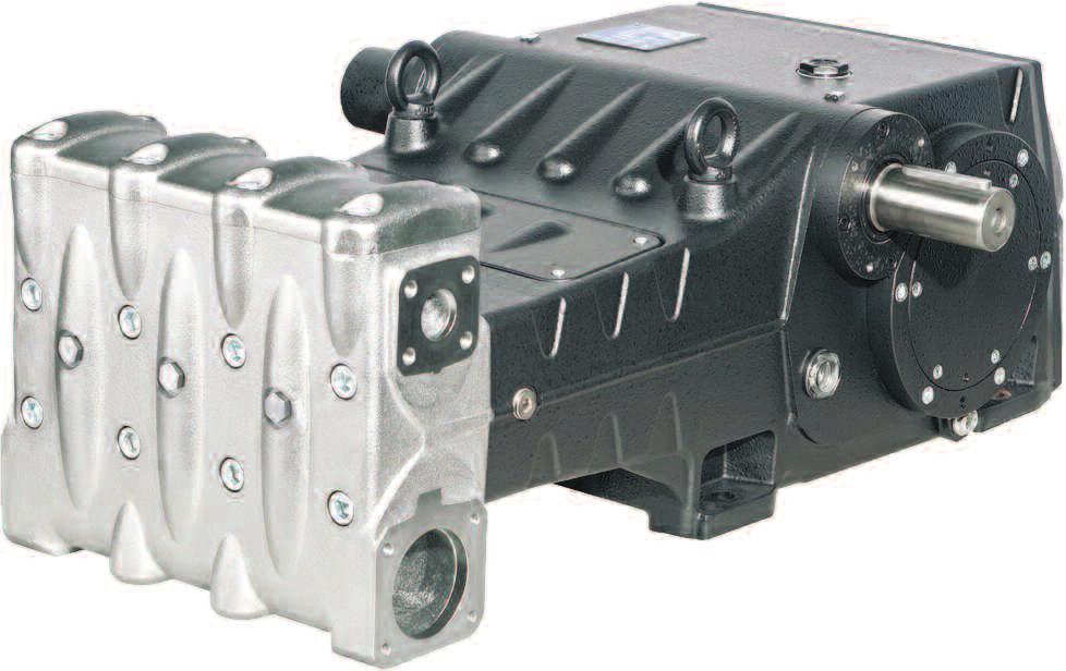
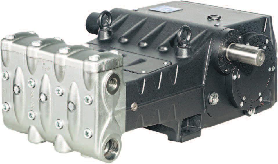
1 LK Repair Manual LK36-LK40-LK45 LK50-LK55-LK60
2 INDEX 1. INTRODUCTION Page 3 2. REPAIR INSTRUCTIONS Page Repair of the Mechanical Part Page Dismantling the Mechanical Parts Page Assembling the Mechanical Parts Page Classes of Increase Page Repair of the Hydraulic Parts Page Head Disassembly - Valve Units Page Head Assembly - Valve Units Page Disassembling the Plunger Unit - Supports - Seals Page Assembly of the Plunger Unit - Suports - Seals Page SCREW CALIBRATION Page REPAIR TOOLS Page MAINTENANCE LOG Page 50 Page 2


3 1. INTRODUCTION This manual contains the instructions for repairing LK Series pumps, and must be carefully read and understood before performing any repair intervention on the pump. Correct use and adequate maintenance is fundamental for the pump s regular operation and long wear. General Pump declines any responsibility for damage caused by the misuse or the non-observance of the instructions described in this manual. 2. REPAIR INSTRUCTIONS 2.1 Repair of the Mechanical Parts Repairs on the mechanical parts must be carried out after removing the oil from the crankcase. To remove the oil, remove the oil fill plug, pos. 1, fig. 1 and then the drain plug, pos. 2, fig.1 present on both side of the crankcase. Exhausted oil must be collected in an appropriate container and disposed of in an authorized location. Do not under any circumstances discard into the environment. Page 3
.")

 Unscrew the M6 locking grub screws from the three oil seal covers (pos.1, fig.2).")
4 2.1.1 Dismantling the Mechanical Parts The correct sequence is the following: Completely drain the oil of oil, as indicated in 2.1. Remove the valve lifters from the head and the head from the pump casing as shown in (from fig. 103 to fig. 105). Detach the upper inspection cover and the lower inspection cover by unscrewing the 4 attachment screws, as shown in point (fig. 129 and fig. 140). Slip off the O-rings and replace them if necessary. Remove the three plungers and the liner/gasket support assemblies, as shown in (fig. 138, fig. 141 and fig. 142). Remove the three spray guard spacer rings and the spray guards, as shown in (fig. 143 and fig. 144) Unscrew the M6 locking grub screws from the three oil seal covers (pos.1, fig.2). Screw in a threaded bar or an extractor M6 screw in the holes in the oil seal covers (pos. 1, fig.3) and remove the covers from the pump assembly (pos. 1, fig. 4). Page 4
 and the outside O-ring (pos.")

 Unscrew the attachment screws from the")
5 Take out the radial seal ring, (pos. 1, fig. 5) and the outside O-ring (pos.1, fig 6). Remove the lug from the PTO shaft (pos. 1, fig. 7) Unscrew the attachment screws from the shaft end cover (pos. 1, fig. 8) and slip the cover off the PTO shaft. Page 5
 and remove it.")


6 Unscrew the crankcase cover attachment screws (pos. 1, fig. 9) and remove it. Slip off the O-ring and replace it if necessary. Now remove the two bearing covers by unscrewing the screws (pos. 1, fig10). To help with their removal, use 2 M8 grub screws or screws (pos. 1, fig 11) as extractors. Slip off the O-ring and replace if necessary. Insert a shim under the shank of the central connecting rod, to stop the rotation of the crankshaft (pos. 1, fig. 12). Page 6
.")
.")

, but do not remove it.")
7 Unscrew and take out the bushing locking flange attachment screws, from both sides (pos. 1, fig. 13). The bushing locking flanges must be left in position (pos. 1, fig. 14). On one side, screw a ferrule (type SKF KM20) onto the pressure bushing (pos. 1, fig. 15), and then unblock the bushing using a striking hammer (pos. 1, fig 16), but do not remove it. Repeat the operation on the other side. Remove the shim from under the shank of the central connecting rod. Page 7


.")
8 Unscrew the connecting rod screws (pos.1, fig. 17). Dismantle the small ends of the connecting rods with the half-bearings. During the operation take particular care to note the order in which the parts are removed The connecting rod small ends and the big end halves must be reassembled in exactly the same order and pairings in which they were dismantled. To prevent any errors, small ends and big end halves are numbered on one side (pos. 1, fig. 18). Advance the three big end halves as far as possible in the direction of the head. Slip off the three upper halfbearings of the beg end halves (pos. 1, fig 19). Page 8
.")


9 Take out both of the pressure bushings (pos. 1, fig. 20). Separate the bushing locking flange from the pressure bushing (pos. 1, fig. 21). Unscrew the screws of the two bearing support covers (pos. 1, fig. 22). Page 9
 and, while keeping it raised, take out the bearing support cover")


10 Apply an M16 threaded pin to one end of the crankshaft (pos. 1, fig. 23) and, while keeping it raised, take out the bearing support cover complete with bearing and O-ring (pos. 1, fig. 24). To help with their removal, use 2 M10 grub screws or screws (pos. 2, fig. 23) as extractors. Repeat the operation on the other side Lay the crankshaft on the bottom of the crankcase. Separate the bearing support cover from the bearing, using a striking hammer (pos. 1, fig. 25). Unscrew the attachment screws of the left and right PTO bearing cover (pos. 1, fig. 26) and slip the two covers off the PTO shaft. To help with their removal, use 3 M8 grub screws or screws (pos. 1, fig. 27) as extractors. Page 10
 and the outside O-ring (pos. 1, fig.")

.")
, take out the PTO crankshaft from either")
11 Take out the radial seal ring (pos. 1, fig. 28) and the outside O-ring (pos. 1, fig. 29) and the lubrication hole O-ring (pos. 1, fig. 30) Roll back the three connecting rods as far as possible (until they touch the crankshaft). Using a striking hammer or mallet (pos. 1, fig. 31), take out the PTO crankshaft from either one of the two sides (pos. 1, fig. 32). Page 11
 and also slip off the two internal bearing spacers (pos.")


12 Slip the internal bearing rings off the PTO shaft (pos. 1, fig. 33) and also slip off the two internal bearing spacers (pos. 2, fig. 33). The internal and external bearing rings must be reassembled in exactly the same order and pairings in which they were dismantled. Using a sufficiently long bar (pos. 1, fig. 34) and a striking hammer, take the bearing rings out of the pump casing (pos. 1, fig. 35), along with the external spacer (pos. 1, fig. 36) and the bearing lubrication bushing (pos. 1, fig. 37). Page 12
 (pos. 1, fig. 38).")
 F2756620) to unlock the")
 and then take out the connecting rod/piston head assemblies from the")
13 Advance the big end halves in the direction of the hydraulic part and lock them in place using the special tool (p/n F ) (pos. 1, fig. 38). Move the crankshaft from the lower part of the casing (pos. 1, fig. 39). Proceed to unscrew the screws of the device (p/n) F ) to unlock the connecting rods (pos. 1, fig. 40) and then take out the connecting rod/piston head assemblies from the rear opening of the casing (pos. 1, fig. 41). Page 13
. Remove the two pin-locking Seeger rings using the correct tool (pos. 1, fig. 43).")
14 Couple the big end halves to the small ends that were previously dismantled, with reference to their numbering scheme (pos. 1, fig. 42). Remove the two pin-locking Seeger rings using the correct tool (pos. 1, fig. 43). Page 14
.")


15 Slip out the pin (pos. 1, fig 44) and take out the connecting rod (pos. 1, fig. 45). To separate the stem from the piston head, it is necessary to unscrew the hexagonal-head M10 screw using a no. 17 socket wrench (pos. 1, fig. 46). Complete the disassembly of the mechanical parts by removing the oil level lights and the eyebolts Assembling the Mechanical Parts Proceed with the assembly, following the reverse of the procedure shown in 2.2.1/ The correct sequence is as follows: Attach the two oil level lights and the two oil drain plugs (pos. 1 and 2, fig. 47). Page 15
 as shown in section 3, Screw tightening settings.")
.")

16 Connect the stem to the piston head. Insert the Ø 5 roll pin in the hole on the piston head (pos. 1, fig. 48) and connect the stem to the piston head using a M10x35 screw (pos. 1, fig 49). Place the stem in a vice, closing the teeth of the vice on the two flat areas, and proceed with setting, using a torque wrench (pos. 1, fig. 50) as shown in section 3, Screw tightening settings. Insert the connecting rod into the piston head (pos. 1, fig. 45) and then insert the pin (pos. 1, fig. 44). Apply the two shoulder Seeger rings using the correct tool (pos. 1, fig. 43). The assembly is correct if the small end, piston head and pin rotate freely. Separate the small ends from the big end halves. Correct pairing is ensured by the numbering on one side (pos. 1, fig. 42). After verifying that the casing is perfectly clean, insert the big end half/piston head assembly into the cylinder tube in the casing (pos. 1, fig. 41). The big end half/piston head assembly must be inserted into the housing with the numbering of the big end halves visible from above. Lock the three assemblies using the special device (p/n F ) (pos. 1, fig. 40). Lock the crankshaft through the rear opening of the casing and lay it on the bottom. Page 16
 (pos. 1, fig. 52).")
 and an external bearing ring (pos. 1, fig. 54) using a pad and a mallet or striking hammer.")
17 The crankcase must be inserted into the casing so that the teeth on the ring bevel gears are oriented as shown in fig. 51. Pre-assemble the PTO shaft: Onto the PTO shaft, slip on the 2 internal rings of the bearings (one per side) (pos. 1, fig. 52). The internal and external bearing rings must be reassembled in exactly the same order and pairings in which they were dismantled. From one side of the casing, insert the bearing lubrication bushing (pos. 1, fig. 53) and an external bearing ring (pos. 1, fig. 54) using a pad and a mallet or striking hammer. Page 17
 and roll back the connecting rods until they tough the crankshaft.")


.")
18 Remove the device for locking the connecting rods (p/n F ) (pos. 1, fig 40) and roll back the connecting rods until they tough the crankshaft. Insert the pre-assembled PTO shaft into the casing (pos. 1, fig. 55). Insert it from the other side to the side where the external bearing ring and the bearing lubrication bushing were inserted. The PTO shaft must be inserted into the casing so that the teeth are oriented as shown in fig. 55. It is easier to insert the PTO shaft completely inside the bearing by applying an M16 screw to the end of the shaft being inserted, to keep the shaft lifted up (pos. 1, fig. 56). From the side of the casing where the PTO shaft was inserted, proceed to insert the bearing lubrication bushing (pos. 1, fig. 57) and an external bearing ring (pos. 1, fig. 58) using a pad and a mallet or striking hammer. Page 18

 and the external bearing")

 of a bearing from one side")
19 At both sides, insert the internal bearing spacers (pos. 1, fig. 59) and the external bearing spacers (pos. 1, fig. 60). Insert the internal ring (pos. 1, fig. 61) and external ring (pos. 1, fig. 62) of a bearing from one side of the pump only. Page 19

20 Pre-assemble the left and right PTO covers: Insert the radial seal ring into the PTO bearing cover using the correct tool (F ) (pos. 1, fig. 63). Before proceeding with the assembly of the radial seal ring, verify the condition of the seal lip. If it is necessary to replace it, position the new ring as shown in fig. 64. If the PTO shaft shows diametral wear corresponding to the seal lip, then to avoid grinding you can position the ring as a second step as shown in fig. 64. Apply the external O-ring (pos. 1, fig. 65) and the lubrication hole O-ring (pos. 1, fig. 66) to the PTO bearing covers. Page 20
. Be careful of the direction of assembly of cover.")
 and external ring (pos. 1, fig. 62) of the second bearing.")

21 Mount one of the PTO bearing covers (left or right) on the pump casing (pos. 1, fig. 67) and attach it with four M8X30 screws (pos. 1, fig. 68). Be careful of the direction of assembly of cover. The lubrication hole in the cover must correspond to the hole in the casing. Repeat the operations on the other side: Insert the internal ring (pos. 1, fig. 61) and external ring (pos. 1, fig. 62) of the second bearing. Mount the second PTO bearing on the pump casing (pos. 1, fig. 67) and attach it with 4 M8X30 screws (pos. 1, fig. 68). Tighten the 4 screws with a torque wrench, as shown in section 3, Screw Tightening Settings. Pre-assemble the two bearing covers: Insert the bearing using a mallet or striking hammer (pos. 1, fig. 69) until 4 to 4.5 mm of the bearing is still protruding, as shown in fig. 70 Page 21


22 The bearing in fig. 70 has a conical internal ring. Verify that the conicity is from the out side to the inside to allow the subsequent insertion of the bushing. Apply the O-ring to the outside of the bearing support cover (pos. 1, fig. 71). Repeat the operation with the other cover. Lock the three connecting rod assemblies, using the special tool (F ) (pos. 1, fig 40). Apply two M16 threaded pins to the end of the crankshaft and, while keeping it raised (pos. 1, fig. 72), insert the bearing support cover complete with bearing and O-ring )pos. 1, fig. 73) using a mallet or striking hammer. Repeat the operation on the other side. Page 22
.")


23 Fasten the bearing support covers with 6 M10X30 screws (pos. 1, fig. 74). Tighten the screws with a torque wrench, as shown in section 3. Screw Tightening Settings. Partly insert the two pressure bushings, keeping the crankshaft lifted up by means of the previously mounted M16 pin (pos. 1, fig. 75). Insert the pressure bushing completely onto the crankshaft (pos. 1, fig. 76 and fig. 77) using a mallet or striking hammer and a pad. Page 23

 M16 screw to the M16 hole on the crankshaft and screw it in, until the flange is touching the bushing (pos. 1, fig. 79).")
24 The pressure bushing must be inserted dry (no lubricant). Insert the bushing until the outside (conical) surface perfectly couples with the inside of the bearing. During insertion, make sure that the bearing stays in contact with the crankshaft shoulder. Repeat the operation on the other side. Insert the bushing locking flanges into the conical bushings (pos. 1, fig. 78). Apply a sufficiently long (30-40 mm) M16 screw to the M16 hole on the crankshaft and screw it in, until the flange is touching the bushing (pos. 1, fig. 79). DO NOT TIGHTEN THE SCREW. Repeat the operation on the other side. Remove the tool for locking the connecting rods (F ) (pos. 1, fig. 40). Page 24
 To correctly assemble the half-bearings, make sure that the lug on the half-bearing is positioned in the")
. Apply the lower half-bearings to the small ends (pos. 1, fig.")
 Attach the small ends to the big end halves using the M12X1.25X87 screws (pos. 1, fig. 83).")

25 Insert the upper half-bearings between the connecting rods and the crankshaft (pos. 1, fig. 80) To correctly assemble the half-bearings, make sure that the lug on the half-bearing is positioned in the slot on the big end half (pos. 1, fig. 81). Apply the lower half-bearings to the small ends (pos. 1, fig. 82), making sure that the lugs on the half-bearings are positioned in the slots on the small ends (pos. 1, fig. 82) Attach the small ends to the big end halves using the M12X1.25X87 screws (pos. 1, fig. 83). Tighten the screws with a torque wrench, as shown in Section 3, Screw Tightening Settings, bringing the screws to the tightening torque at the same time. When the operation is finished, check that the connecting rods have axial clearance in both directions. When the operation is finished, check that the connecting rods have axial clearance in both directions. Page 25


26 Insert a shim under the shank of the central connecting rod, to stop the rotation of the crankshaft (pos. 1, fig. 84). Measure the distance X indicated in fig. 85 between the conical bushing and the crankshaft bearing. Screw in the M16 screw until there is a reduction in the distance X of between 0.7 mm and 0.8 mm (fig. 86). Page 26

. Apply LOCTITE 243 to the threads of the M12X25 screws (pos.")


27 Repeat the operation on the other side. Remove the M16 screw from the crankshaft. Screw the two bushing locking flanges onto the crankshaft using 4 M12X25 screws (pos. 1, fig. 87). Apply LOCTITE 243 to the threads of the M12X25 screws (pos. 1, fig. 87). Tighten the screws with a torque wrench, as shown in section 3, Screw Tightening Settings. Remove the anti-rotation shim from under the shank of the central connecting rod. Mount the two bearing covers (with their O-rings) (pos. 1, fig. 89) using 6 M8X20 screws (pos. 1, fig. 90). Tighten the screws with a torque wrench, as shown in section 3, Screw Tightening Settings. Page 27

.")

 using a pad (F27910900).")
28 Insert the O-ring into the rear cover (pos. 1, fig. 91) and affix it to the casing using 10 M8X20 screws (pos. 1, fig. 92). Tighten the screws with a torque wrench, as shown in section 3 Screw Tightening Settings. Mount the radial seal ring onto the oil seal cover (pos. 1, fig. 93) using a pad (F ). Position the O-ring (pos. 1, fig. 94) on the seat of the oil seat cover. Page 28
, being careful not to damage the lip of the radial seal ring.")

. Insert O-rings on the two inspection covers (pos. 1, fig.")
29 Insert the assembly into the casing and into the seat provided, making sure that the cover completely enters its seat (pos. 1, fig. 95), being careful not to damage the lip of the radial seal ring. Screw in the oil seal covers using 2 M6X30 grub screws (pos. 1, fig. 96). Tighten the screws with a torque wrench as shown in section 3, Screw Tightening Settings. Position the spray guard and the spray guard spacer ring in the seat on the piston head stem (pos. 1, fig.97and fig. 98). Insert O-rings on the two inspection covers (pos. 1, fig. 99) and mount the covers using 4 M6X14 screws (pos. 1, fig. 100). Page 29

.")
30 Tighten the screws with a torque wrench, as shown in section 3, Screw Tightening Settings. Mount the shaft end cover and affix it to the casing using 3 M8X20 screws (pos. 1, fig. 101). Tighten the screws with a torque wrench, as shown in section 3 Screw Tightening Settings. Apply the lug to the PTO shaft (pos. 1, fig. 102). Page 30
31 2.1.3 Classes of Increase INCREASE TABLE FOR CRANKSHAFT AND CONNECTION ROD HALF-BEARINGS Recovery Classes (mm) Upper half bushing p/n Lower half bushing p/n Crank pin grinding measures (mm) Ø /-0.03 Roughness Ra 0.4 Rt 3.5 Ø /-0.03 Roughness Ra 0.4 Rt 3.5 INCREASE TABLE FOR PUMP CASING AND PISTON HEAD Recovery Classes (mm) Piston Head p/n Crank pin grinding measures (mm) Ø 81 H /0 Roughness Ra 0.8 Rt Repair of the Hydraulic Parts Dismantling the head - the valve assemblies The head requires preventive maintenance as indicated in the Owner s Manual. Operations are limited to inspection or replacement of the valves, when necessary. To extract the valve assemblies work as follows: Unscrew the valve lifter using a 30 mm spanner (pos. 1, fig. 103). Page 31

. Take care to not subject the plungers to knocks or")


32 Apply two supports with G2 threading to the outlet connections of the head (pos. 1, fig. 104) and then unscrew the 8 M16X150 screws (pos. 1, fig. 105). Take care to not subject the plungers to knocks or bumps when taking them out of the head. Unscrew and remove the 8 M16X55 screws of the valve cover (pos. 1, fig. 106) and remove the cover (pos. 1, fig. 107). Remove the valve plug by using a slide hammer puller applied to the M10 hole in the valve plug (pos.1, fig. 108). Page 32

, use the extractor tool F27516400 (for")
33 Slide out the spring (pos. 1, fig. 109). Remove the outlet valve assembly by using a slide hammer puller applied to the M10 hole in the valve holder (pos. 1, fig. 110). If it is particularly difficult to remove the outlet valve assembly (e.g. there are build up deposits because the pump has not been used for a long period), use the extractor tool F (for LK36,40,45) or p/n F (for LK50, 55, 60). Take out the valve holder spacer, using an 8mm hexagonal key (pos. 1, fig. 111). Page 33

, use the extractor")
 and use it as shown in the diagram.")
34 Remove the inlet valve assembly by using a slide hammer puller applied to the M10 hole in the valve holder (pos. 1, fig. 112). If it is particularly difficult to remove the outlet valve assembly (e.g. there are build up deposits because the pump has not been used for a long period), use the extractor tool F (for LK36,40,45) or p/n (for LK50, 55, 60) (pos. 1, figs 113) and use it as shown in the diagram. Remove the inlet and outlet valve assemblies by screwing in an M10 screw so as to attach it to the inside holder and take out the valve holder from the valve seat (pos. 1, fig. 114). Page 34


, and then dry these seats completely.")

35 2.2.2 Assembling the Head - The Valve Assemblies Check the state of wear of the various components very carefully and replace them if necessary. At each inspection of the valves, replace all the O-rings, both for the valve assemblies and for the valve plugs. Before repositioning the valve assemblies, clean their seats in the head, located by the arrows (pos. 1, fig. 115), and then dry these seats completely. Proceed with the assembly, following the reverse of the disassembly procedure shown in Assemble the inlet and outlet valve assemblies (fig. 116 and fig. 117), taking care not to reverse the springs that were previously removed. To facilitate insertion of the valve holder into the seat, place a pipe on the horizontal flat surface of the holder (fig. 118) and use a mallet/striking hammer around the entire circumference. Page 35


. Insert the O-ring, exploded position #5, from Owner s Manual, (pos.")

36 Proceed with the insertion of the valve assemblies (inlet and outlet) into the head, taking care to follow the correct insertion sequence of the O-rings and the anti-extrusion rings. The correct assembly sequence for the valve assemblies in the head is as follows: Insert the anti-extrusion ring, exploded Position #4, from Owner s Manual, (pos. 4, fig. 119). Insert the O-ring, exploded position #5, from Owner s Manual, (pos. 1, fig. 120). Make sure the O-ring and anti-extrusion ring are perfectly seated in place. Insert the inlet valve assembly (pos. 1, fig 121). The complete valve assembly must be inserted all the way in, as shown in pos. 1, fig Page 36


37 Mount the O-ring, exploded position #5, from Owner s Manual, (pos. 1, fig. 123) and the anti-extrusion ring, exploded position #15 (pos. 2, fig. 123), onto the outlet valve seat. Insert the outlet valve assembly (pos. 1, fig. 124). The valve assembly must be inserted all the way in, as shown in pos. 1, fig Insert the anti-extrusion ring, exploded position #16 (pos. 1, fig. 126). Page 37


 or p/n F27516100")

38 Insert the O-ring, exploded position #17 (pos. 1, fig. 127) Be very careful when inserting the O-ring indicated in pos. 1, fig We recommend using the special tool, p/n F (for LK36, 40, 45) or p/n F (for LK50, 55, 60), to prevent the O-ring from being cut during insertion. Insert the valve seat ring (pos. 1, fig. 129 and the spring (pos. 1, fig. 130). Page 38
, onto the outlet valve plug. Insert the valve plug, complete with O-ring and anti-extrusion ring.")
 and screw in the 8 M16X55 screws (pos. 1, fig.")
39 Mount the O-ring, exploded position #17 (pos. 1, fig. 131) and the anti-extrusion ring, exploded position #21 (pos. 2, fig 131), onto the outlet valve plug. Insert the valve plug, complete with O-ring and anti-extrusion ring. After insertion of the valve assemblies and the valve plugs is complete, replace the valve cover (pos. 1, fig. 132) and screw in the 8 M16X55 screws (pos. 1, fig. 133). Attach the head to the pump casing (pos. 1, fig. 134) taking care not to subject the plungers to knocks or bumps, and screw in the 8 M16X150 screws (pos. 1, fig. 135). Page 39


40 Proceed to tighten the M16X150 screws with a torque wrench, as shown in section 3 Screw Tightening Settings. Tighten the 8 M16X150 screws, beginning by cross-tightening the 4 inside screws (see fig. 135) and then moving on to the 4 outside screws, again, cross-tightening them. Tighten the M16X55 screws of the cover with a torque wrench, as shown in section 3, Screw Tightening Settings. Insert the valve lifters (pos. 1, fig. 136) and screw them in using a 30 mm spanner (pos. 1, fig. 137). Page 40


41 2.2.3 Dismantling the Plungers-Supports-Seals Assembly The plunger assembly requires regular inspection as indicated in the preventive maintenance table in the Owner s Manual. Operations are limited to a visual check for any draining from the hole in the lower cover. If there are anomalies/oscillations in the outlet pressure gauge, or drips from the drain hole, then the seal packing must be checked and, if necessary, replaced. To extract the plunger assemblies, work as follows: To access the plunger assembly, unscrew the M16X150 screws and dismantle the head. Take the greatest care when sliding out the head to avoid subjecting the plungers to knocks or bumps. Remove the plungers by unscrewing the attachment screws (pos. 1, fig. 138). Slide the plunger from the gasket support and check that its surface does not have scratches, signs of wear or cavitation. Remove the upper inspection cover (pos. 1. fig. 139) and the lower inspection cover (pos. 1, fig. 140) by unscrewing the 4 attachment screws. Page 41

.")


42 Manually rotate the shaft to bring the 3 plungers into the top dead center position. Insert the plastic buffer (p/n F ) between the plunger head and the plunger (pos. 1, fig. 141). By rotating the shaft, advance the plunger head so that the plastic buffer advances in its turn and expels the gasket support and the entire plunger assembly (pos. 1, fig. 142). Remove the gasket support assembly and the plastic buffer. Slip the spray guard spacer rings off the plunger heads (pos. 1, fig. 143) and also the spray guards (pos. 1, fig. 144). Page 42

 and unscrew the support until it is completely")


43 Separate the gasket support from the liner by using a compass spanner with Ø 5 round ends, available on the market, (pos. 1, fig. 145) and unscrew the support until it is completely removed (pos. 1, fig. 146). Manually remove the head rings, the pressure gaskets and the restop rings (pos. 1, fig. 147). To remove the low pressure gasket, use a feeler gauge or other tool that does not damage the gasket support seat (pos. 1, fig. 148). Page 43

, and taking great care not to damage them while inserting")


. Insert the head ring (pos. 1, fig.")
44 2.2.4 Assembling the Plungers - Supports - Seals Assembly Proceed with the reassembly, following the reverse of the disassembly procedure shown in Replace the pressure gaskets, moistening the lips with silicone grease (without covering the gaskets), and taking great care not to damage them while inserting them into the liner. At every disassembly, the pressure gaskets must always be replaced, together with all the O-rings. Insert the low pressure gasket into the gasket support (pos. 1, fig. 149), taking care to follow the direction of assembly: the seal lip goes in front (towards the head). Insert the head ring (pos. 1, fig. 150), the high pressure gasket (pos. 1, fig. 151) and the restop ring (pos. 1, fig. 152). Place the O-ring for the gasket support on its seat (pos. 1, fig. 153). Page 44
 and tighten using a compass spanner with Ø 5 round ends,")
, until the support abuts the liner.")
.")
45 Screw the gasket support to the liner (pos. 1, fig. 154) and tighten using a compass spanner with Ø 5 round ends, available on the market (pos. 1, fig. 155), until the support abuts the liner. Place the 14x2 O-ring on its seat on the plunger attachment screw (pos. 1, fig. 156). Place the plungers on their respective holders (pos. 1, fig. 157) and fix them in place as in pos. 1, fig Page 45


46 Tighten the screws with a torque wrench, as shown in section 3, Screw Tightening Settings. Insert the previously assembled liner/gasket support block (complete with its two O-rings, until it is snugly in place (pos. 1, fig. 159). Make sure that the liner/support block goes all the way in and is correctly positioned on its seat (pos. 1, fig. 160). Place the frontal O-ring on the liner (pos. 1, fig. 161) and also the O-ring for the recirculation hole (pos. 1, fig. 162). Page 46


47 Insert the O-rings on the inspection covers (pos. 1, fig. 163) and mount the covers using 4 M6X14 screws (pos. 1, fig. 164). Page 47
48 3. SCREW CALIBRATION Screws are to be fastened exclusively using a torque wrench. Description Exploded View Position (From Owner s Manual) Fastening Ft. Lbs. Fastening Nm M8x20 screw, casing cover G1/2x13 plug, casing M8x30 screw, PTO bearing cover M8x20 screw, shaft end cover M10x30 screw, bearing support cover M6x14 screw, upper & lower covers M8x20 screw, bearing cover M12x1.25x87 screw, connecting rod tightening * M10x35 screw, plunger head M12x25 screw, bushing locking flange M10x160 screw, plunger attachment M16x55 screw, valve cover G1/4 x13 screw, head M16x150 screw, head ** Valve lifter * Reach the tightening torque by tightening the screws simultaneously. ** Tightening sequence always cross-wise starting from the 4 internal screws (see fig. 135) then the 4 external screws. Page 48
49 4. REPAIR TOOLS Pump maintenance may be carried out using simple tools for assembling and disassembling components. The following tools are available: For Assembly: Plunger head radial seal ring p/n F PTO shaft radial seal ring p/n F O-ring, outlet valve seat (LK36, LK40, LK45) p/n F O-ring, outlet valve seat (LK50, LK55, LK60) p/n F For Disassembly: Inlet valve seat (LK36, LK40, LK45) p/n F Inlet valve seat (LK50, LK55, LK60) p/n F Outlet valve seat (LK36, LK40, LK45) p/n F Outlet valve seat (LK50, LK55, LK60) p/n F Liner + gasket support block p/n F Shaft (for locking connecting rods) p/n F Page 49
50 MAINTENANCE LOG HOURS & DATE OIL CHANGE GREASE PACKING REPLACEMENT PLUNGER REPLACEMENT VALVE REPLACEMENT GP Companies, Inc Northland Drive Mendota Heights, MN Phone: Fax: Ref Rev.A Page 50
Repair Manual MWS45A-MWS50A-MWS55A MW32A-MWS36A-MWS40A. Ref Rev.D General Pump is a member of the Interpump Group
 MW/S 8 Repair Manual MWS45A-MWS50A-MWS55A MW32A-MWS36A-MWS40A General Pump is a member of the Interpump Group INDEX 1. INTRODUCTION..................................................Page 3 2. REPAIR INSTRUCTIONS...........................................Page
Repair Manual MK40A-MK45A-MK50A MK55A-MK60A-MK65A. Ref Rev.C General Pump is a Member of The Interpump Group
 MK Repair Manual MK40A-MK45A-MK50A MK55A-MK60A-MK65A General Pump is a Member of The Interpump Group 8 INDEX 1. INTRODUCTION..................................................Page 3 2. REPAIR INSTRUCTIONS...........................................Page
MKS. MKS Series MKS 40 MKS 45 MKS 50 MKS 55 MKS 60 MKS 65. Repair Manual
 MKS Series MKS 40 MKS 45 MKS 50 MKS 55 MKS 60 MKS 65 Repair Manual INDEX. INTRODUCTION 3 2. REPAIR INSTRUCTIONS 3 2. Crank Mechanism Repair...3 2.. Crank Mechanism Disassembly...4 2..2 Crank Mechanism
Click Here to Go Back
 Click Here to Go Back Fig. -94 Fig. -97 CC42D 10. Remove the cap screw securing the gear shift stopper plate pin retainer; then remove the retainer. Fig. -95 CC45D 12. Remove the link arm and account for
ELECTRIC TOOL CORPORATION
 Cat. No. -0 / Hex Demolition Hammer Cat. No. 0-0 Spline Rotary Hammer MILWAUKEE ELECTRIC TOOL CORPORATION W. LISBON ROAD BROOKFIELD, WISCONSIN 00-0 -9-00 d 000 -9-00 d SpecialTools Require Forcing discs
Removing Right-Side. Components. Right-Side. Components. Click Here to Go Back AT THIS POINT
 Click Here to Go Back NOTE: There is an oil passage beneath the driven gear/drive gear assembly. This passage should be plugged prior to removing the driven gear and drive gear. Failure to do so could
Maintenance Information
 16601023 Edition 2 January 2014 Air Impact Wrench 2705P1 Maintenance Information Save These Instructions Product Safety Information WARNING Failure to observe the following warnings, and to avoid these
Fisher 667 Diaphragm Actuators Size 80 and 100
 Instruction Manual 667 Size 80 and 100 Actuators Fisher 667 Diaphragm Actuators Size 80 and 100 Contents Introduction... 1 Scope of Manual... 1 Description... 2 Specifications... 2 Maximum Pressure Limitations...
REPAIR INSTRUCTIONS. Cat. No Cat. No MILWAUKEE ELECTRIC TOOL CORPORATION. SDS Max Demolition Hammer. SDS Max Rotary Hammer
 Cat. No. 9-0 SDS Max Demolition Hammer Cat. No. -0 SDS Max Rotary Hammer MILWAUKEE ELECTRIC TOOL CORPORATION W. LISBON ROAD BROOKFIELD, WISCONSIN 00-0 8-9-0 d 000 8-9-0 d Special Tools Require Forcing
A-PDF Split DEMO : Purchase from to remove the watermark SHAFT DRIVE
 SHAFT DRIVE 4-1 A-PDF Split DEMO : Purchase from www.a-pdf.com to remove the watermark SHAFT DRIVE CONTENTS SECONDARY BEVEL GEARS... 4-2 CONSTRUCTION... 4-2 REMOVAL... 4-4 DISASSEMBLY... 4-4 INSPECTION...
SUPER PRO GUN & SUPER PRO GUN II
 MAGNUM VENUS PRODUCTS Maintenance & Repair Manual Part No. M6707-1-1 Revision 04.14.01 Maintenance & Repair Corporate HQ & Mfg. Phone: (727) 573-2955 Fax: (727) 571-3636 Email: info@magind.com Web: www.magind.com
General Four-Way Operation, Maintenance & Service Manual
 General Four-Way Operation, Maintenance & Service Manual SCOPE Included in the following pages you will find assembly drawings, exploded views, parts lists, assembly tips, operational descriptions and
The Virgo/Libra Steam Engine
 The Virgo/Libra Steam Engine Congratulations on becoming the owner of a Virgo or Libra Steam Engine. With careful use and maintenance it will give many years of satisfying performance. Contents 1) Notes
DO35 MAINTENANCE INSTRUCTIONS
 CUSTOMER INFORMATION SHEET NO. 038 DO35 MAINTENANCE INSTRUCTIONS (DO35 V3 LAUNCHED PRODUCTION JUNE 2017) Table of Contents 1.0 Replacing Spindle Bushes V3... 22 2.0 Replacing Locking Mechanism V3... 6
Additional Information
 NUMBER: 1 34 13 S.M. REF.: Listed in Table ENGINE: EPA04/07 Series 60 DATE: January 2013 SUBJECT: CHECKING CYLINDER LINER PROTRUSION ADDITIONS, REVISIONS, OR UPDATES Publication Number Platform Section
Series 760 Heavy Duty Fixed Displacement Motor. Parts and Repair Manual
 Series 760 Heavy Duty Fixed Displacement Motor Parts and Repair Manual Series 760 Fixed Displacement Motor Contents Introduction 3 ID Tag Information 3 Parts List 4 Parts Drawing 5 Disassembly Instructions
OTECO INC. MODEL ,000 PSI 4-1/16 PORT DM GATE VALVE MAINTENANCE MANUAL
 Page 1 of 7 OTECO INC. MODEL 45 4 5,000 PSI 4-1/16 PORT DM GATE VALVE MAINTENANCE MANUAL Page 2 of 7 TABLE OF CONTENTS 1. Assembly Blowout 2. Repair Kit Contents & Technical Specifications 3. Disassembly
Inspection. Assembly Install the springs. 1. Discard the 0-rings. 2. Clean all parts in cleaning solvent.
 6010-34 Inspection 3. Install the springs. 1. Discard the 0-rings. 2. Clean all parts in cleaning solvent. 3. If spring test equipment is available, check the tension of each spring according to the specifications
BRAVO STERN DRIVE 3 C BRAVO ONE
 RAVO STERN DRIVE 3 C 22439 RAVO ONE Table of Contents Page Specifications............................... 3C-1 Torque Specifications..................... 3C-1 Preloads................................ 3C-1
SERVICE I IPL, Service Tools, Service Tools
 SERVICE I0300046 IPL, Service Tools, 2003-01 Service Tools 1 1 Contents Service s A. Hands, general purpose B. Pressure testing s C. Ignition system D. Carburettor, fuel pump E. Starter device F. Clutch,
OPERATION AND MAINTENANCE FOR MODEL MRV050A REVERSIBLE
 OPERATION AND MAINTENANCE FOR MODEL MRV050A REVERSIBLE MANUAL AIR MOTOR 04666770 Edition 1 April, 1999 IMPORTANT SAFETY INFORMATION ENCLOSED. READ THIS MANUAL BEFORE OPERATING TOOL. FAILURE TO OBSERVE
Chiltern Model Steam Engines
 Chiltern Model Steam Engines Mill Twin Cylinder Model Steam Engine v2 Assembly Instructions v1.0 Notes: 1. In overview the engine should first be assembled "dry" with no oil/lubricants, thread lock or
W-K-M Model MA-1 DynaCentric Butterfly Valve
 Page 1 of 16 R E P A I R M A N U A L W-K-M Model MA-1 DynaCentric Butterfly Valve Page 2 of 16 Published October 2001 W-K-M and DynaCentric are trademarks of Cooper Cameron Corporation Cooper Cameron Corporation,
DRIVE COMPONENTS REMOVAL. 9. FXCW/C: see Figure Remove bolt (9), sprocket retainer (8), and thrust washer (7). NOTE PRIMARY DRIVE LOCKING TOOL
, sprocket retainer (8), and thrust washer (7). NOTE PRIMARY DRIVE LOCKING TOOL") DRIVE COMPONENTS REMOVAL PART NUMBER HD-7977 TOOL NAME PRIMARY DRIVE LOCKING TOOL S To remove the primary chain, remove compensating sprocket, clutch assembly and primary chain as an assembly:. Remove
DRIVE COMPONENTS REMOVAL PART NUMBER HD-7977 TOOL NAME PRIMARY DRIVE LOCKING TOOL S To remove the primary chain, remove compensating sprocket, clutch assembly and primary chain as an assembly:. Remove
RIPPER PEDAL. Bearing / Axle Replacement. ( Disassembly )
") RIPPER PEDAL Bearing / Axle Replacement ( Disassembly ) 1 1. Use good quality tools to avoid stripping screw sockets. 2. When servicing your pedals, work on one side at a time to prevent parts from mixing
RIPPER PEDAL Bearing / Axle Replacement ( Disassembly ) 1 1. Use good quality tools to avoid stripping screw sockets. 2. When servicing your pedals, work on one side at a time to prevent parts from mixing
w w w. h d o n l i n e s h o p. d e TIMKEN BEARING CONVERSION TOOL GENERAL INSTALLATION -J04672 REV Kit Number Models
 -J067 REV. 008-07- GENERAL Kit Number 8-08 Models TIMKEN BEARING CONVERSION TOOL For model fitment information, see the P&A Retail Catalog or the Parts and Accessories section of www.harley-davidson.com
MODELS 49 RA 49 RAZ 49 RAC
 General Safety and Maintenance Manual MODEL grinder featuring a rear exhaust. Model Number Exhaust Direction REAR Throttle Type (L) Lever or (K) Safety Lever Speed 12000 to 14000 R.P.M (13500rpm is standard)
Eaton Hydrostatic Fixed Motors. Repair Information. Series 1 Models Hydrostatic Fixed Motors. Motors with Valve Blocks
 Eaton Hydrostatic Fixed Motors September, 1997 Repair Information Motors with Valve Blocks Motors with Integral Shuttle and Low Pressure Relief Valves Series 1 Models 33-64 Hydrostatic Fixed Motors Table
MUELLER. Improved, Centurion Series, Modern Improved, and 107. Fire Hydrants. Inserting Extention Sections. Reliable Connections
 insertion Instructions manual MUELLER Improved, Centurion Series, Modern Improved, and 107 table of contents PAGE Centurion Series Fire Hydrant Adding an Extention 2-3 Improved Fire Hydrant Inserting Extention
JARVIS. Model25CL-4,5,6 Hock Cutter and Loin Dropper. 25CL--5 Front Legs and Horns. 25CL--4 Hind Legs and Horns. 25CL--6 Loins
 Model25CL-4,5,6 Hock Cutter and Loin Dropper 25CL--4 Hind Legs and Horns 25CL--5 Front Legs and Horns 25CL--6 Loins EQUIPMENT SELECTION... Ordering No. TABLE OF CONTENTS... Page 25CL--4... 4025007 25CL--5...
SERVICE PARTS LIST. M18 FUEL SAWZALL Reciprocating Saw F56A BULLETIN NO CATALOG NO
 47(5x) 46 45 00 44 0 59 43 42 84 51 57 46 47 48 59 83 64 77 48 47(2x) 49(2x) 40 58 See service note on page 5 41 82 51 40 41 42 43 44 45 87 52 27 28 34 57 29 (6x) 60 28 EXAMPLE: Component Parts (Small
BETTIS SERVICE INSTRUCTIONS FOR MODELS G01 THROUGH G10 SERIES HYDRAULIC SPRING RETURN ACTUATORS WITH M11 HYDRAULIC OVERRIDE
 ENGLISH LANUAGE BETTIS SERVICE INSTRUCTIONS FOR MODELS G01 THROUGH G10 SERIES HYDRAULIC SPRING RETURN ACTUATORS WITH M11 HYDRAULIC OVERRIDE PART NUMBER: 127072E REVISION: A DATE: December 2001 Page 1 of
Engineering Data Single Reduction Parts List Item # Description Basic Single Reduction Unit 1. Gear Housing 2. Pipe Plug 3. Vent Plug 4. Splash Guard
 Engineering Data Single Reduction Parts List Item # Description Basic Single Reduction Unit 1. Gear Housing 2. Pipe Plug 3. Vent Plug 4. Splash Guard 5. Input Cover 6. O-Ring 7. Hex Head Cap Screw 8. Input
MUELLER. Improved, Centurion Series, Modern Improved, and 107. Fire Hydrants. Inserting Extension Sections. Reliable Connections
 insertion Instructions manual MUELLER Improved, Centurion Series, Modern Improved, and 107 table of contents PAGE Centurion Series Fire Hydrant Adding an Extension 2-3 Improved Fire Hydrant Inserting Extension
PROSTEER BALL JOINT REBUILD INSTRUCTIONS V1.0
 DYNATRAC PRODUCTS 2003-2010 4X4 DODGE 2500/3500 HEAVY DUTY BALL JOINT PROSTEER BALL JOINT REBUILD INSTRUCTIONS V1.0 WARNING: Improper use or installation of this product can cause major failures that could
JARVIS. Model Brisket Scissor EQUIPMENT... TABLE OF
 Model 423-17 Brisket Scissor EQUIPMENT SELECTION... Ordering No. TABLE OF CONTENTS... Page Model 423--17... 4037003 Air Filter / Regulator / Lubricator 3022003 Air Hose Assembly... 3059018 Balancer...
OPERATION AND MAINTENANCE INSTRUCTIONS AVK UNDERGROUND FIRE HYDRANT
 1. INTRODUCTION Operation and maintenance manual for the series underground CLEARWAY fire hydrant 1 of 7 The designs, materials and specifications shown are subject to change without notice due to our
Fisher 667 Diaphragm Actuator Sizes 30/30i 76/76i and 87
 Instruction Manual 667 Actuator (Size 30/30i - 76/76i and 87) Fisher 667 Diaphragm Actuator Sizes 30/30i 76/76i and 87 Contents Introduction... 1 Scope of Manual... 1 Description... 2 Specifications...
Page 1. SureMotion Quick-Start Guide: LARSACC_QS 1st Edition - Revision A 03/15/16. Standard Steel Bolt/Screw Torque Specifications
 R K C T I Repair Kit Product Compatibility Repair Kit # Linear Actuator Assembly # LARSACC-013 LARSACC-014 LARSD2-08T12BP2C (12-in travel) LARSD2-08T24BP2C (24-in travel) C P I R K 1 ea Ball Screw with
GH BETTIS SERVICE INSTRUCTIONS DISASSEMBLY & REASSEMBLY FOR MODEL F10207 DOUBLE ACTING HYDRAULIC ACTUATOR
 GH BETTIS SERVICE INSTRUCTIONS DISASSEMBLY & REASSEMBLY FOR MODEL F10207 DOUBLE ACTING HYDRAULIC ACTUATOR PART NUMBER: 074960 REVISION: "A" RELEASE DATE: NOVEMBER, 1991 Page 1 of 6 1.0 INTRODUCTION 1.1
LPK1550 Hydraulic Crimping Tool 15-ton
 SERVICE MANUAL LPK1550 Hydraulic Crimping Tool 15-ton Serial Code FYF Read and understand all of the instructions and safety information in this manual before operating or servicing this tool. Register
DYNATRAC BALL JOINT REBUILD INSTRUCTIONS V4.0
 DYNATRAC PRODUCTS 2007-2016 4X4 JEEP JK HEAVY DUTY BALL JOINT JP44-2X3050-C DYNATRAC BALL JOINT REBUILD INSTRUCTIONS V4.0 WARNING: Improper use or installation of this product can cause major failures
Mechanical Technical Assistance Manual for washers
 1 Mechanical Technical Assistance Manual for washers, GIRBAU, S.A. Crta de Manlleu, km. 1 08500 VIC (Barcelona) SPAIN Tel. 34 93 8861100 Fax 34 93 8860785 girbau@girbau.es www.girbau.com For USA & CANADA:
H8508 Impact Wrench SERVICE MANUAL. Model (Serial Code FWN) Model (Serial Code FWP)
 Model (Serial Code FWP)") SERVICE MANUAL H8508 Impact Wrench Model 48755 (Serial Code FWN) Model 48760 (Serial Code FWP) Read and understand all of the instructions and safety information in this manual before operating or servicing
SERVICE MANUAL H8508 Impact Wrench Model 48755 (Serial Code FWN) Model 48760 (Serial Code FWP) Read and understand all of the instructions and safety information in this manual before operating or servicing
No September, Char-Lynn. Power Steering. Repair Information. 20 Series Steering Control Unit 001
 Char-Lynn Power Steering No. 7-313 September, 1997 Repair Information 20 Series Steering Control Unit 001 Bearing Race Retaining Ring Needle Thrust Bearing Bearing Race Seal Ring Backup Washer Seal (3
Type XTSR71 Sizes
 (Page 1 of 13) s 494-5258 Type XTSR71 s 494-5258 Figure 1 Thomas XTSR71 Coupling 1. General Information 1.1 Thomas Couplings are designed to provide a mechanical connection between the rotating shafts
Specifications. Engine Dimensions. Dimensions in millimeters. Inch equivalents shown in [] Rev. -- 5KohlerEn
![Specifications. Engine Dimensions. Dimensions in millimeters. Inch equivalents shown in [] Rev. -- 5KohlerEn](/thumbs/86/94602263.jpg "Specifications. Engine Dimensions. Dimensions in millimeters. Inch equivalents shown in [] Rev. -- 5KohlerEn") Engine Dimensions Dimensions in millimeters. Inch equivalents shown in []. 24 690 0 Rev. -- 5KohlerEn ENGINE IDENTIFICATION NUMBERS Kohler engine identiþcation numbers (model, speciþcation and serial)
Engine Dimensions Dimensions in millimeters. Inch equivalents shown in []. 24 690 0 Rev. -- 5KohlerEn ENGINE IDENTIFICATION NUMBERS Kohler engine identiþcation numbers (model, speciþcation and serial)
RTI TECHNOLOGIES, INC.
 RTI TECHNOLOGIES, INC. BRC500 & BRC550 Arbor/Spindle Mechanism Adjustment & Service Technical Instructions The arbor/spindle mechanism of the BRC500/550 is designed to be robust for long life. Occasionally
PRODUCT SERVICE MANUAL FOR CIG Mechanical Seal Triple Pumps
 PRODUCT SERVICE MANUAL FOR CIG Mechanical Seal Triple Pumps WARNING The Imo General Installation Operation, Maintenance, and Troubleshooting Manual, (No. SRM00046), as well as all other component manuals
NUMBER: S.M. REF.: Listed in Table ENGINE: Series 50/50G DATE: October 2013 SUBJECT: MACHINING CYLINDER BLOCK COUNTERBORES
 NUMBER: 10 25 13 S.M. REF.: Listed in Table ENGINE: Series 50/50G DATE: October 2013 SUBJECT: MACHINING CYLINDER BLOCK COUNTERBORES ADDITIONS, REVISIONS, OR UPDATES Publication Number Platform Section
WSG 8-115; 8-125; P; WSG ; WSG P; WSG PS; WSG P; WSG 15-70Inox
 Repair instructions Page of 47 Contents. Models described 2. Technical data 3. Notes and requirements 4. Tools required 5. Lubricants and auxiliary substances required 6. Disassembly 7. Assembly 8. Connection
AFB (AIR FAN BEARING) INSTALLATION GUIDE
 INSTALLATION GUIDE") 654 AFB (AIR FAN BEARING) INSTALLATION GUIDE AFB PARTS Bearing Housing - Secured together with two 3/8 x 1.25 in. Cap Screws Black Wiper Seals - Secured together with O-ring cord (Subsequently depicted
654 AFB (AIR FAN BEARING) INSTALLATION GUIDE AFB PARTS Bearing Housing - Secured together with two 3/8 x 1.25 in. Cap Screws Black Wiper Seals - Secured together with O-ring cord (Subsequently depicted
Page 1. SureMotion Quick-Start Guide: LACPACC_QS 1st Edition - Revision A 03/15/16
 R K C T I Repair Kit Product Compatibility Repair Kit # Linear Actuator Assembly # LACPACC-002 LACPACC-003 LACP-16TxxLP5 (0.5-in lead screw pitch) LACP-16TxxL1 (1-in lead screw pitch) C P I R K 4 ea Flanged
Cam Handle Service Guide
 Cam Handle Service Guide Page 2. Introduction Page 3. Troubleshooting guide Page 4-5. Adjusting the clamp force Page 6-7. Disassembling, greasing and replacing components Page 8-9. Replacing the post bearings
MODEL SK61732 COMPRESSOR SERVICE KIT
 MODEL SK61732 COMPRESSOR SERVICE KIT For use on 607 and 617 Model Compressors with.32 Stroke WARNING: Unplug the compressor before beginning disassembly. CAUTION: Improper assembly or use of damaged parts
OPERATIONAL AND MAINTENANCE MANUAL. Drilling machine ProDrill 20 INSTRUCTION MANUAL FOR USE AND MAINTENANCE
 MOD 14-02 OPERATIONAL AND MAINTENANCE MANUAL Rev. 0 Data 01/02/2012 Drilling machine ProDrill 20 INSTRUCTION MANUAL FOR USE AND MAINTENANCE TABLE OF CONTENTS TECHNICAL SPECIFICATIONS 2 USE 4 MAINTENANCE
Disassembly. & Reassembly. S Series. Twin Screw Pumps. MAAG E-02EMEA TO REPLACE MAAG E-01
 Disassembly & Reassembly S Series Twin Screw Pumps W h e r e I n n o v a t i o n F l o w s www.maag.com MAAG-14020-E-02EMEA TO REPLACE MAAG-14020-E-01 TABLE OF CONTENTS SECTION 1 INTRODUCTION... 1 SAFETY
3-506 NOTE: CC054D
 Click Here to Go Back Fig. 3-506 NOTE: Position the shift lever part way onto the splines and verify the subtransmission is in Hi range. If not, shift into Hi range. Fig. 3-509 CC054D 25. Place the speedometer
3/8-16 x 3/4 cap screw. 3/8-16 hex nut for above screws. 1/4-20 x 3/4 socket cap screw. 3/16 short arm hex key (not to scale)
") Super Slab Roller 24, 30 and 36 models Worktable Assembly Directions P.O. Box 89 Cheney, WA 99004 USA 509.235.9200/800.23.7896 Fax: 509.235.9203 www.northstarequipment.com Revised September, 2006. All
Super Slab Roller 24, 30 and 36 models Worktable Assembly Directions P.O. Box 89 Cheney, WA 99004 USA 509.235.9200/800.23.7896 Fax: 509.235.9203 www.northstarequipment.com Revised September, 2006. All
CAUTION INSTALLATION INSTRUCTIONS ! CAUTION. E-Z Flex Suspension Kits for Double Eye Springs. Safety Precautions: Inspection: Disassembly:
 INSTALLATION INSTRUCTIONS E-Z Flex Suspension Kits for Double Eye Springs K71-652-00 E-Z Flex Complete Kit for Tandem Axles with 33" Axle Spacing, 6000 Lb. Max Capacity K71-653-00 E-Z Flex Complete Kit
MOTOR & BULK HEAD. A Manual for Repair and Maintenance Technicians
 MOTOR & BULK HEAD A Manual for Repair and Maintenance Technicians CAUTION This manual is designed to help technicians who are already experienced in workshop procedures and know how to handle tools. Only
Power Train Lift Max. Capacity: 1,250 lbs.
 655 EISENHOWER DRIVE OWATONNA, MN 55060 USA PHONE: (507) 455-7000 TECH. SERV.: (800) 533-6127 FAX: (800) 955-8329 ORDER ENTRY: (800) 533-6127 FAX: (800) 283-8665 INTERNATIONAL SALES: (507) 455-7223 FAX:
INSTRUCTION MANUAL Q-HYDRAULIC
 Dat: 15.04.02 No: 94-BA 5039E/1b TABLE OF CONTENTS Part III 3.0 Type code explanation 3.1 Service connections 3.2 Impeller clearance adjustment 3.2.1 Wear of wearing parts 3.2.2 General notes to adjustment
H4670/42192 Submersible Trash Pump
 SERVICE MANUAL H4670/42192 Submersible Trash Pump Serial Code GLW Read and understand all of the instructions and safety information in this manual before operating or servicing this tool. 99916070 REV
Cut-True 16M Manual Paper Cutter
 Cut-True 16M Manual Paper Cutter 2/2013 OPERATOR MANUAL FIRST EDITION TABLE OF CONTENTS TOPIC PAGE Specifications 1 Safety Guidelines 1 Assembly 2 Overview 3 Description of Equipment Parts 3-4 Operation
Instructions for the installation of Ellison Bronze balanced door models #137 & 138
 1. A packing list will be found in crate No. 1 of each shipment. The parts in the crates should be checked with this list. If there is any discrepancy, notify Ellison Bronze at once. 2. All parts are numbered.
Motorized M3 AX7200 Rotary-Style Gasket Cutter Operating Instructions
 Motorized M3 AX7200 Rotary-Style Gasket Cutter Operating Instructions INTRODUCTION Congratulations! You are the owner of the finest rotary-style gasket cutter in the world. Originally developed and patented
Hardinge FlexC Dead-Length Collet System Style DL. Installation Instructions and Parts Lists. FlexC Collet System Style DL Instructions B-152
 Hardinge FlexC Dead-Length Collet System Style DL Installation Instructions and Parts Lists 1 General Safety Information Before installing the Hardinge FlexC Collet System on your machine tool, thoroughly
CQ Tilting Pad Thrust Bearings
 CQ Tilting Pad Thrust Bearings Installation and Maintenance Instructions 1. Introduction The following notes provide installation and assembly instructions for Waukesha Bearings CQ tilting pad thrust bearings.
BETTIS SERVICE INSTRUCTIONS FOR MODELS G01 THROUGH G13 SERIES HYDRAULIC ACTUATORS WITH POWER MODULE TIE BAR CONSTRUCTION
 ENGLISH LANGUAGE BETTIS SERVICE INSTRUCTIONS FOR MODELS G01 THROUGH G13 SERIES HYDRAULIC ACTUATORS WITH POWER MODULE TIE BAR CONSTRUCTION PART NUMBER: 124839E REVISION: C DATE: 06 July 2006 Page 1 of 31
PORTABLE PULL TESTER
 2425 West Vineyard Avenue, Escondido, California 92029-222 Phone: (800) 284-4460 Fax: (760) 746-4295 PORTABLE CABLE TERMINAL PULL TESTER AT520CT (Revised July 2003) AT520CT Portable Cable Terminal Pull
AR-15 Lower Receiver Assembly Instructions
 AR-15 Lower Receiver Assembly Instructions Tools There are a few tools that make it easier to put together these kits, but none of them are necessary. Minimum requirements include a hammer and punch to
Fig Remove chain cover plate bolts. Fig Remove hammer member. Fig Loosen set screws at base of 12-tooth sprocket.
 Fig. 17.2. Remove chain cover plate bolts. Fig. 17.1. Remove hammer member. Fig. 17.3. Remove chain cover plate. Fig. 17.4. Loosen set screws at base of 12-tooth sprocket. Page 61 Fig. 17.5. Remove socket
CAUTION INSTALLATION INSTRUCTIONS ! CAUTION. Heavy Duty Suspension Kits for Double Eye Springs. Safety Precautions: Inspection: Disassembly:
 INSTALLATION INSTRUCTIONS Heavy Duty Suspension Kits for Double Eye Springs K71-358-00 for Single Axles K71-359-00 for Tandem Axles with 33" Axle Spacing K71-360-00 for Triple Axles K71-448-00 for Tandem
YALE FIGURE 500 & 500R CLOSURE OPERATION AND MAINTENANCE INSTRUCTIONS
 YALE FIGURE 500 & 500R CLOSURE OPERATION AND MAINTENANCE INSTRUCTIONS IMPORTANT INFORMATION Note To Supervisor: Please share this information with your employees and make sure they have received training
S E L E C T I O N. Arm Curl. User manual
 S E L E C T I O N T H E S T R E N G T H E V O L U T I O N User manual The identification plate of the and manufacturer, affixed behind the seat, gives the following details: A Name and address of the manufacturer
DYNATRAC BALL JOINT REBUILD INSTRUCTIONS V5.0
 DYNATRAC PRODUCTS 2007-2018 JEEP JK HEAVY DUTY BALL JOINT JP44-2X3050-C DYNATRAC BALL JOINT REBUILD INSTRUCTIONS V5.0 WARNING: Improper use or installation of this product can cause major failures that
PEDESTAL OVERHAUL. Some of the tools for a pedestal overhaul. Pedestal work stand
 INTRODUCTION A properly greased labyrinth seal will help prevent dust and water damage to the pedestal bearing oil supply and shaft seal area. Properly greased and oiled pedestals rarely require an overhaul.
Auto-Spreader Spreader HS10K Hydraulic Flange Spreader
 Auto-Spreader Spreader HS10K Hydraulic Flange Spreader US Patent No. 5678293 Operation and Maintenance Manual Keep For Your Records Contents Operation...2 Maximum Spreader Extension...3 Safety Tips...4
Mechanical Frappe Press
 Mechanical Frappe Press Operation Manual CONTENTS OPERATIONAL INSTRUCTIONS PRECAUTIONS PART NAMES INCLUDED ITEMS BASIC OPERATION MAINTENANCE REPLACEMENT PARTS Thank you for using The Frapptastic Five Mechanical
SECTION 7 - SUSPENSION
 For Arctic Cat Discount Parts Call 606-678-9623 or 606-561-4983 SECTION 7 - SUSPENSION TABLE OF CONTENTS Section Front and Rear Suspension Assembly Schematics... 7-2 Shock Absorbers... 7-4 Swing Arms (ACT
Owner s Manual AE PLUG AERATOR MANUFACTURING QUALITY LAWN CARE EQUIPMENT SINCE Made In CHINA REV
 MANUFACTURING QUALITY LAWN CARE EQUIPMENT SINCE 1945 Owner s Manual AE-48 48 PLUG AERATOR IMPORTANT Read and follow all Safety Precautions and Instructions Before Operating this Equipment. Made In CHINA
MAINTENANCE INSTRUCTIONS
 INDEX MAINTENANCE INSTRUCTIONS FOR PUMP RANGE GT Standard Models Quality Assured to ISO 9001 and BS 5750 since 1985 for the Design, Manufacture and Repair of Sealless Pumps and Drives HMD/KONTRO SEALLESS
Fisher 657 Diaphragm Actuators Size 80 and 100
 Instruction Manual 657 Size 80 and 100 Actuators Fisher 657 Diaphragm Actuators Size 80 and 100 Contents Introduction... 1 Scope of Manual... 1 Description... 2 Specifications... 3 Installation... 3 Actuator
pneumatic c-ring tool
 pneumatic c-ring tool hc5 HC5 WARNINGS! Always read tool manual before operating tool. Always wear safety glasses when operating or while in the area where a tool is being used. When test cycling tool
Installation Instructions
 The IMS ETERNAL FIX PATENT PENDING Installation Instructions EPS recommends professional installation for the Eternal IMS Fix. Please take all precautionary safety measures. We also recommend putting the
KL50000 Counter Bore OPERATING INSTRUCTIONS. U.S. Patent No CA Patent No
 KL50000 Counter Bore Re-Condtioning Tool Kit OPERATING INSTRUCTIONS U.S. Patent No. 8.308.401 CA Patent No. 2667147 315 Garden Avenue Holland, MI 49424 klineindustries.com 1-800-824-KLINE (5546) cservice@klineind.com
AT ADAPTER INSTALLATION INSTRUCTIONS
 IMPORTANT: THIS IS A HIGH PERFORMANCE PART AND IMPROPER INSTALLATION COULD RESULT IN INJURY OR DEATH! NEVER WORK UNDER AN AUTOMOBILE THAT IS NOT PROPERLY SUPPORTED AND BLOCKED FROM ROLLING. NO CREDIT OR
Chin Strap, Sealed Pull Pins and Swing Catch for Fiberglass Helmets. Contents
 Chin Strap Chin Strap, Sealed Pull Pins and Swing Catch for Fiberglass Helmets Contents BTM-1 1.1 Chin Strap BTM-4 1.2.3.1 Preparation BTM-1 1.1.1 Chin Strap Removal BTM-4 1.2.3.2 Disassembly BTM-1 BTM-2
LORON SERVICE MANUAL / PARTS LIST SINGLE DOUBLE PALLET HANDLER CONTENTS: PAGE 1 Lift Truck Requirements General Installation Procedures
 LORON SERVICE MANUAL / PARTS LIST SINGLE DOUBLE PALLET HANDLER CONTENTS: PAGE 1 Lift Truck Requirements General Installation Procedures 2 Mounting Options Stop Block Adjustments 3 General Weekly Inspection
Door window. Front door window, assembly overview
 64-50 Door window Front door window, assembly overview 1 - Window channel Pushed onto flange 2 - Door window Removing Page 64-52 Adjusting Page 64-53 3 - Door 4 - Outer window channel Pushed onto flange
G01 through G10 Series Hydraulic Actuators Double-Acting with M11 Hydraulic Override Disassembly and Reassembly
 Service Instructions G01 through G10 Series Hydraulic Actuators Double-Acting with M11 Hydraulic Override Disassembly and Reassembly Service Instructions Table of Contents Table of Contents Section 1:
4.2 - PUMP MAINTENANCE MODELS: AC, AS, WC, WS
 4.2 - PUMP MAINTENANCE MODELS: AC, AS, WC, WS 4.2.1 - EXPLODED VIEW DRAWING REF NO. 1 2 4 QTY 3 1 1.5 5 ¾ HP HP HP HP HP DESCRIPTION PART # 1 CASE 1.25 x 1 NPT 018266 1 CASE 1.25 X 1 NPT 018268 1 CASE
1. TABLE OF CONTENT 2. ASSEMBLY ATEX. PENCOflex Installation Instructions & Service Manual
 ATEX 1. TABLE OF CONTENT 1. Table Of content... 1 2. Assembly... 1 3. Alignment... 2 4. Earthing... 3 5. Inspection and replacement of Elastic elements... 4 5.1. Rubber elements... 4 5.2. Pins... 4 5.2.1
To remove sanding pad, turn counterclockwise.
 Disassembly Instructions - Dynorbital EXTREME Models: All Important: Disconnect sander from the air supply. Notice: Use these instructions along with the tool manual. To avoid damage, use the special repair
25000 Series Lo-T TM Butterfly Control Valve Instructions
 November 2001 25000 Series Lo-T TM Butterfly Control Valve Instructions Instruction No. 25.1:IM PRELIMINARY STEPS Before installation, note the flow direction arrow on the valve body. The flow should enter
Service instructions. CR, CRI, CRN 10, 15 and /60 Hz 1/3~
 Service instructions CR, CRI, CRN 10, 15 and 20 50/60 Hz 1/~ 1. Type identification... 2 1.1 Nameplate... 2 1.2 Type key... 1. Code for shaft seal... 4 2. Tightening torques and lubricants... 5. Service
EMB MANUFACTURING INC.
 TRAILER WOODSPLITTER MODEL SE80CR ASSEMBLY INSTRUCTION MANUAL Please review and understand the operators manual before attempting to operate this machinery. EMB MANUFACTURING INC. 4144 BOOMER LINE ST.
MODEL D DIESEL PILE HAMMER
 AMERICAN PILEDRIVING EQUIPMENT, INC. MODEL D125-42 DIESEL PILE HAMMER SPARE PARTS BOOK Corporate Office 7032 S. 196th Street Kent, WA, USA 98032 Tel: 1-800-248-8498 Tel: 1-253-872-0141 Fax: 1-253-872-8710
QB78 CO 2 Pellet Rifle
 QB78 CO 2 Pellet Rifle Maintenance Instructions Text and photos by George Fox Lang The Chinese QB78 pellet rifle is one of the nicest and most popular CO 2 rifles ever produced. Here are the long-wanted