LIST PARTS. A\ACHINE No THE SINGER MANUFACTURING COMPANY. From the library of: Superior Sewing Machine & Supply LLC
|
|
|
- Liliana Flynn
- 5 years ago
- Views:
Transcription
1 Form ( 1141 ) Printed in U. S. A. LIST OF PARTS A\ACHINE No THE SINGER MANUFACTURING COMPANY
2 INSTRUCTIONS FOR OILING Lift out the arm reservoir gauge and fill the oil reservoir to the level mark on the gauge. Run the machine a few minutes, then check the oil level and, If necessary, fill to the mark on the gauge. Remove the screw plug on the balance wheel and fill the reservoir practically to the top. THIS OIL LEVEL SHOULD NEVER BE ALLOWED TO 00 BELOW THE HOLE AT THE CENTER OF THE ARM SHAFT. Apply about 5 drops of oil to each of the three oil cups for the ball bearings and to the oil cup on the Idler pulley beneath the balance wheel. Place a drop of oil once a day In the oil hole directly above the nipper. When the machine Is first started, put a few drops of oil In the top of the needle bar guide pin over the needle bar. Thereafter, when the machine Is In continuous use, re plenish the oil supply about twice a week. Use only "singer Stainless Oil for High Speed Sewing Machines". Copyright, U. S. A., 1939 and 1941 by The Singer Manufacturing Co. All Rights Reserved for all Countries
3 INDEX Page Accessories 18 Belt Guards 18 Foot Lifter and Starting Treadle Parts 18 Front Planks 19 Idlers 20 Lap Seam Feller 21 Machine Cushions 21 Machine No Numerical List of Parts 23 Power Table Accessories 22 Thread unwinder (for Four Cones) 22 Thread unwinder Spool Rests 22
4 INSTRUCTIONS FOR ORDERING In ordering from this list, use ONLY the part NUMBER In the FIRST column. The number stamped on a Sewing Machine Part Is In every case the number of the single part only. Every combination of parts sent out as such has its specific number, which, although not stamped on the parts, must be used when ordering the combination. Each number always Indicates the SAME PART In whatever list It appears, or for whatever machine. The letters after some of the numbers Indicate the style of finish only, as follows: A-Hardened, Polished, Nickel Plated and Buffed A.A-Buffed and Chromium Plated A.B-Hardened, Polished, Buffed and Chromium Plated A.C-Brown Baking Enamel Finish A.D-Gray Baking Ekiamel Finish A.B-Hardened, Bright Rumbled and Nickel Plated A.F-Hardened, Bright Rumbled, Nickel Plated, Bright Rumbled and Chromium Plated A.G-Alumlllte, Plain A.H-Alumlllte, Dyed A.J-Pollshed, Nickel Plated and Chromium Plated A.K-Hardened, Polished, Nickel Plated and Chromium Plated A.L-Heat Treated for Toughness B-Pollshed, Nickel Plated and Buffed C-Hardened Only C.R-Hardened and Merllzed D-Polished Only E-Soft, Not Polished F-Hardened and Polished F.J-Hardened, Polished and Nickel Plated 6-Brlght Rumbled and Nickel Plated H-Blued J-Nlckel Plated Only K-Hardened and Nickel Plated L-Brass Plated M-Qxldlzed N-Japanned, Dull P-Japanned, Bright P.P-Wrlnkle Finish R-Merllzed S-Cadmium Plated T-Copper Plated T.A-Hardened, Polished, Copper and Nickel Plated and Buffed T.B-Copper and Nickel Plated and Polished T.J-Copper and Nickel Plated Only T.K-Hardened, Copper and Nickel Plated T.L-Copper and Brass Plated T.M-Copper Plated and Oxidized
5 INSTRUCTIONS FOR ORDERING - Continued U-Zlnc Plated V-Sllver Plated W-Polished and Nickel Plated X-Black Oxide, for Iron and Steel X.C-Hardened and Black Oxide, for Iron or Steel Y-Black Nickel Plated Only Z-Chromlum Plated Z.A-Hardened,Pollshed,Nlckel Plated,Buffed and Chromium Plated Z.B-Pollshed, Nickel Plated, Buffed and Chromium Plated Z.C-Hardened and Chromium Plated Z.D-Pollshed and Chromium Plated Z.Q-Brlght Rumbled, Nickel Plated, Bright Rumbled and Chromium Plated Z.J-Nlckel and Chromium Plated Z.T-Copper and Chromium Plated These letters MUST BE USED when they appear In the list; and AFTER the number as In the list. In this series: 1 to 1500, to and to are Screw Numbers 1501 to 1600 and to are Nut Numbers 1801 to 2000 and to are Roller Numbers 2001 to and to and to are Sewing Machine Parts, and upward are numbers of Electrical Parts. The flgiures In the second column refer only to the plates. Illustrating the parts, and are NOT TO BE USED In ordering. Parts marked with as* asterisk ( ) are furnished only when repairs are made at factory. When ordering parts which differ as to Gauge (the distance between seams) the Gauge, as well as the Number must be given on order.
6 Genuine Singer Needles should be used in Singer Machines. These Needles and their Containers are marked with the Company's Trade Mark "SIMANCO." 1 Needles in Containers marked "For Singer Machines" are not Singer made needles.
7 LIST OF PARTS COMPLETE SINQES m t MACHINE No For Light and Medium Weight Fabrics. SMALLER CYLINDER BED for lap seam felling boys' shirts and work of a similar nature. Two needles,two loopers. Needles set in reverse position (right hand needle nearest operator). Gauges from inch to inch, in steps of Standard gauges are Yq inch, %2 '''ch and Yiq inch. Length of stitch 8 to 22 to the inch. Needle bar stroke I Yiq inches. Speed 4300 R. P. M. No R Nanie Arm with and two " Dowel Pin (2) " Hole Plug Screw (for access to Arm Rotary Shaft Crank Set Screw Arm Rotary Shaft " " " With " n " n " n Ball Bearing (hack) n n " Case Arm Rotary Shaft Ball Bearing (back) Case Set Screw
8 8 PARTS P, FOR MACHINE No No. Plate AL P C E AL E C E R Name Arm Rotary Shaft Ball Bearing (back) Oil Cup Arm Rotary Shaft Ball Bearing (back) Oil Cup Oil Pad (braided cotton) Arm Rotary Shaft Ball Bearing (back) Spacing Collar Arm Rotary Shaft Ball Bearing (front)... n ti 11 ti n It Cup Arm Rotary Shaft Ball Bearing (front) Oil Cup Oil Pad (braided cotton)... Arm Rotary Shaft Ball Bearing (front) Oil Retainer (back) Arm Rotary Shaft Ball Bearing (front) Oil Retainer (front) ' Arm Rotary Shaft Crank with two each 1036AL and 1149AL Arm Rotary Shaft Crank with Arm Rotary Shaft Crank Set Screw (2)... " " " Screw " " " Sprocket Wheel with two each C and Arm Rotary Shaft Sprocket Wheel Set Screw (2) Arm Rotary Shaft Sprocket Wheel Spring Flange (2) Arm Screw (3) Balance Wheel, 2 In. pulley, with two 51283AL, for round belt Balance Wheel, "v" belt groove, with two 51283AL Balance Wheel Set Screw (2) Bed " Cover with 50411E and " " Gasket (cork) " " " Clamping Plate in n It n «Screw... " " Hole Plug Screw " " " " " Screw " (16) " Washer *' Extension " " Screw (2) " Oil Drain Plug Screw " " " " " Gauge " " Washer " Rotary Shaft " " " Ball Bearing (Inter mediate) Bed Rotary Shaft Ball Bearing (Inter mediate) Sleeve with two 462AL
9 PARTS FOR MACHINE No No. Plate 462AL R E P D D C J E W Nanie Bed Rotary Shaft Ball Bearing (inter mediate) Sleeve Set Screw (2) Bed Rotary Shaft Ball Bearing (left).,.. " " ' " " " Cover n n II n n n n Gasket Bed Rotary Shaft Ball Bearing (left) Cover Screw (4) Bed Rotary Shaft Ball Bearing (right)... " " " "» " Case II II II ti 11 II n Nut Bed Rotary Shaft Ball Bearing (right) Case Screw (3) Bed Rotary Shaft Ball Bearing (right) Oil Cup Bed Rotary Shaft Ball Bearing (right) Oil Cup Oil Pad (braided cotton)... Bed Rotary Shaft Ball Bearing (right) Spacing Collar Bed Rotary Shaft Belt " " " " Guard with two 20C363C : Bed Rotary Shaft Belt Guard Cover II n n n n II With Bed Rotary Shaft Belt Guard Cover Gasket (cork) Bed Rotary Shaft Belt Guard Cover Screw (2) Bed Rotary Shaft Belt Guard Set Screw (2) Bed Rotary Shaft Screw (left) " " " " (right) " " " Sprocket Wheel with and two C Bed Rotary Shaft Sprocket Wheel Set Screw (2) Bed Rotary Shaft Sprocket Wheel Spring Flange Face Plate (lower half) " " " " Gasket (cork)... " " tl.1 (gj " " (upper half) " " II II Position Plate.. n II II II Screw Face Plate (upper half) Thumb Screw Feed Bar " " Hinge Pin (eccentric)
10 10 PAf PARTS FOR MACHINE No No. Plate AL Note: 1255E AL J AL C Note: When When AL E QAL AL J Name Feed Bar Hinge Pin Oil Retainer (leather) " " " " Set Screw ** " t* II at 4. nt t Slide Block " Dog, 19 teeth (14 teeth to the Inch) for , for 3/16 In. to 1/4 In. gauges Feed Dog, 18 teeth (14 teeth to the Inch) for , for 1/8 In. and 5/32 In. gauges Feed Dog with row of teeth between needles, 18 teeth (14 teeth to the Inch) for , for 5/32 In, gauge ordering Feed Dogs, state gauge required. Feed Dog Scrw " Eccentric Body Set Screw (2) " " Clamping Washer n n n n _ Screw... Feed Eccentric (adjustable) complete, N0S.217J,7071, and two 51061AL Feed Eccentric Slide Block " Lifting Eccentric Forked Connection n M ti n n Screw (long) Feed Lifting Eccentric Forked Connection Screw (short) Feed Lifting Eccentric Forked Connection Slide Block Feed Regulating Screw Looper (back) " (front). ordering Loopers, state gauge required. Looper Avoiding Eccentric with two 5015QAL Looper Avoiding Eccentric Forked Connec tion with 1057AL Looper Avoiding Eccentric Forked Connec tion Clamping Screw Looper Avoiding Eccentric Forked Connec tion Shaft Looper Avoiding Eccentric Forked Connec tion Shaft Bracket with 456C Looper Avoiding Eccentric Forked Connec tion Shaft Bracket Screw ^... Looper Avoiding Eccentric Forked Connec tion Slide Block Looper Avoiding Eccentric Set Screw (2) " Clamping Screw " Driving Arm with 1047AL " " " Ball Screw Stud» n n n II n Nut..
11 PARTS FOR MACHINE No No. Plate AL E E AL F AL AL AL J J Name Looper Driving Arm Ball Screw Stud Nut Lock Washer Looper Driving Arm Connecting Link " " " " Hinge Pin (2) Looper Driving Arm Connecting Link Hinge Pin Set Screw (2) Looper Driving Arm Connection with four 175E Looper Driving Arm Connection with and Looper Driving Arm Connection Cap (low er) Screw (2) Looper Driving Arm Connection Cap (up per) Screw (2) Looper Driving Arm Connection Crank with 1057AL Looper Driving Arm Connection Crank Clamping Screw Looper Driving Arm Hinge Stud " n n tt n Cap Screw, n t< n 11 CI n n Washer (lead) Looper Driving Arm Hinge Stud Set Screw, " Eccentric and Feed Lifting Eccen tric with two 1036AL Looper Eccentric and Feed Lifting Eccen tric Set Screw (2) Looper Eccentric Connection with 1047AL. " " " Slide Block. " n n ti n Screw stud Looper Eccentric Connection Slide Block Screw Stud Collar with two 1253AL... Looper Eccentric Connection Slide Block Screw Stud Collar Set Screw (2)... Looper Eccentric Connection Slide Block Screw Stud Set Screw Looper Eccentric Connection Slide Block Screw Stud Washer (leather) Looper Gate (left) with 665J and n n n., _. Lock Spring n n ti n n _ Screw... " H (right) " " " Hinge Stud Connection n n n n ti n Hinge Pin Looper Gate (right) Lock Spring n ti B n n n. Screw... Looper Gate (right) complete, Nos. 665J, ,139451,139454, and two
12 12 PARTS FOR A^ACHINE No No. Plate Name Looper Gate Locking Plate 236J " " " " Screw " " Spring n n n position Pin " Holder with 586E, and 51485AL 586E Looper Holder Clamping Screw " " Shaft n ti n gushing (hack) 443AL ti ti tt ii n Screw Looper Holder Shaft Bushing (front) " n n n " Set Screw Looper Holder Shaft Collar with 1454E E " ti n n clamping Screw Looper Position Pin " Thread Guide 206J " " " Screw Needle Bar (hollow) Needle Bar complete, Nos and Needle Bar Bvishlng (lower) 1133E " " " "Set Screw " " Connecting Link " " " " With and Needle Bar Connecting Link Hinge Stud " " " " " " Oil Pad (braided cotton) 1C86AL Needle Bar Connecting Link Hinge Stud Set Screw (2) Needle Bar Connecting Link Spacing Wash er, thickness.004",.008" or.012". Note: When ordering No , state thickness re E quired Needle Bar Connecting Stud with 175E... " " " " Clamping Screw " " " " Oil Pad (wick) " " " " Slide Block... n n 11 II 11 n Guide 1057AL Needle Bar connecting Stud Slide Block Guide Screw (2) Needle Bar Connecting Stud Slide Block Guide Screw Washer (2) Needle Bar Guide " " " Oil Pad (inside) braided cotton Needle Bar Guide Oil Pad (outside) felt.
13 PARTS FOR MACHINE No No. Plate Name 1133E Needle Bar Guide Set Screw " " Thread Guide S5(M " " " " Screw.* " " " " " washer " " Clamp with two 1498F Guard, for 3/32 In. to 3/16 In. gauges Needle Guard, for 7/32 In. and 1/4 In. Note: gauges When ordering Needle Guards, state gauge re quired Needle Guard Holder 453AL " " " Set Screw!!.* 1167E " Screw 1498F " Set Screw (2) *..!!!!!!!!!! Oil Cup Body " ]" " " " Cap (transparent) " " " " Gasket (cork) " " " " Retainer 131C n ti 11 n n 50617B " " " Oil Plug Screw (4).., " " " " " " washer Oil Cup complete, for oiling Needle Bar Connecting Link,. Nos B, to and four 131C Oil Cup Gasket (soft leather) Presser Bar " " Bushing (lower) 1133E " " " " Set Screw " " Lifting Bracket with 1057AL. 1057AL «n t. n clamping Screw " " " " Lifter 807D nun ii n Hinge" Screw Presser Bar Lifting Lever 802D " " " " Hinge Screw " " " Spring " " Spring!.! Housing " " " Seat (lower) " " " " (upper)!.!! " Foot Plate (back) " " " " Hinge Pin (front) " " " " Hl^e Pin!!!! " " " Connection n " " " " Spring " " Shank Presser Foot (triple hinged) complete, Nos , , , , and three 26276
14 14 PARTS FOR MACHINE No No. Plate Name 190J Presser Foot Screw 50392J Pressure Regulating Thumb Screw 1745J " n n n Tension (looper thread) Body and Thread Guide with C Tension (looper thread) Body Set Screw C " " " Regulating Screw 1423J " ti ti n n Cap Screw Tension (looper thread) Regulating Screw Nut with Tension (looper thread) Regulating Screw Nut Position Pin Tension (looper thread) Spring " " " Tension Plate (3) Tension (looper thread) Tension Plate Position Pin Tension (looper thread) complete, Nos. 1423J,514860,59534,139140, and three Tension (needle thread) Bracket 376J tt II «n Screw " " " Disc (4) 51570C " " " Regulating Thumb Nut (2) Tension (needle thread) Releasing Disc (2) Tension (needle thread) Releasing Pin (2) Tension (needle thread) Releasing Shaft ii n n n n Crank with 624AL Tension (needle thread) Releasing Shaft Crank Connecting Link HOC Tension (needle thread) Releasing Shaft Crank Connecting Link Hinge Screw (2) 624AL Tension (needle thread) Releasing Shaft Crank Set Screw 316C Tension (needle thread) Releasing Shaft Stop Screw 1547J Tension (needle thread) Releasing Shaft Stop Screw Nut 50326C Tension (needle thread) Screw Stud (2) " " " " " with 51570C (2) Tension (needle thread) Spring (2) " " " " Bushing (large) (2)
15 PARTS FOR MACHINE No No. Plate J QAL AL E J J J J J J Name Tension (needle thread) Spring Bushing (small) (2) Tension (needle thread) Thread Quide (double) (2) Thread (looper) Take-up with two 1266AL. " " " Cover " " ci n " n n n Spring n n n n n n Screw Thread (looper) Take-up Cover Position Screw Stud Thread (looper) Take-up Set Screw (2).. " " " Stripper " " n n Plate.. n n nan Bracket Thread (looper) Take-up Stripper Plate Bracket with 219J, 237J, 24CJ, 7071, 51282J, to , to and two each 203J, 207J, 665J and Thread (looper) Take-up Stripper Plate Bracket Screw (2) Thread (looper) Take-up Stripper Plate Screw (2) Thread (looper) Take-up Stripper Plate Thread Guard Thread (looper) Take-up Stripper Plate Thread Guard Screw (2) Thread (looper) Take-up Stripper Screw (2) Thread (looper) Take-up Stripper Screw Washer (2) Thread (looper) Take-up Thread Guard (fibre) Thread (looper) Take-up niread Guide (left) Thread (looper) Take-up Thread Guide (left) Screw Thread (looper) Take-up Thread Guide (right) Thread (looper) Take-up Thread Guide (right) Screw Thread (looper) Take-up Thread Guide (right) Screw Washer Thread (looper) Take-up Thread Separator n n n n n Thread Retainer Thread (looper) Take-up Thread Separator Thread Retainer Screw
16 16 PARTS FOR MACHINE No No. Plate Name Thread (looper) Thread Guide (left) 2S9J " Screw (2) Thread (looper) Thread Guide (right) J " Screw (2) Thread (looper) Thread Guide Bracket J i> n n n n Scrw " n n n fl _. Support 202J n n n n n n Screw (lower) 237J Thread (looper) Thread Guide Bracket Support Screw (upper) Thread (looper) Thread Tube (belt guard) Bushing (4) 203J Thread (looper) Thread Tube (belt guard) Seat Screw (3) Thread (looper) Thread Tube (belt guard) with four Thread (looper) Thread Tube (front of bed) Bushing (4) Thread (looper) Thread Tube (front of bed) complete, Nos and foia* Thread (looper) Thread Tube (front of bed) Cover Thread (looper) Thread Tube (front of bed) Cover with and two 229J Thread (looper) Thread Tube (front of bed) Cover Catch 229J Thread (looper) Thread Tube (front of bed) Cover Catch Screw (2) Thread (looper) Thread Tube (front of bed) Cover Hinge Pin (2) Thread (looper) Thread Tube (front of bed) Cover Hinge Plate (2) 176J Thread (looper) Thread Tube (front of bed) Cover Hinge Plate Screw (2) Thread (looper) Thread Tube (front of bed) Cover Lock Spring Thread (looper) Thread Tube (front of bed) Cover Lock Spring Position Pin Thread (looper) Thread Tube (front of bed) Cover Lock Spring Reinforcing Plate 202J Thread (looper) Thread Tube (front of bed) Cover Lock Spring Screw Thread (looper) Thread Tube (side of bed)
17 PARTS FOR MACHINE No No. Plate J J E J J J J J W F Name Thread (needle) E^relet " " " (side of arm). " " n B n n " " " Screw " " Take-up with 202E " n n Clamping Screw. Extension. Screw Plate. " " " Spring. " " n n n Thread (needle) Take-up complete, Nos, 337J,1449J,54095,68164, and Thread (needle) Take-up (auxiliary) " " n n Clamp n ti n n n Screw Thread (needle) Thread Guide (left) " " t. n B ggj.g (2) Thread (needle) Thread Guide (right)... " " n n n (2) Thread (needle) Thread Guide Bracket... " Cutter (knife) " " Screw (2) " " Thread Guide (Inside) " " " " (outside)... Throat Plate for , for 3/16 In, to 1/4 In. gauges Throat Plate for , for 1/8 In. and 5/32 In. gauges Throat Plate for , for 5/52 In. gauge Throat Plate Screw (3) Trade Mark " " Rivet (2)
18 18 ACCESSORIES No Plate Name Oiler (copper plated) with " Spout, 4 1/2 In. long Screw Driver (large) " " (small) Tweezers (curved) Wrench BELT GUARDS No Plate R Name Belt Guard with two 146R, for use with Bed Extension No , for all applications except for oblique mounting of the machine on Singer Universal Safety Power Tables Belt Guard with two wood screws 3/4 In. No. 9 R.H., for xise with Bed Exten sion No , for use on Singer Universal Safety Power Tables when Machine Is set at an oblique angle.. Belt Guard with two wood screws 1 In.No. 10 R.H. for Series S 39, S 49, S 59 and S 69 Electric Transmitters, for Stand No , for use with Bed Extension No Belt Guard Screw for (2) No FOOT LIFTER AND STARTING Plate Note: When C C (^ TREADLE PARTS FOR INDIVIDUAL MOTORS Name Foot Lifter Chain, 36 In. to 45 In.,with and ordering No. 6439, state length required. Foot Lifter Chain Connecting Link " " " Hook (large) " " " «(small) Foot Lifter Treadle Starting Treadle with two C " " Set Screw (2) " " Shaft " «n C Starting Treadle Shaft Arm Set Screw (2) " " " Bracket (2) " " n tt ^ggg^ two wood screws 1 In. No. 14 F.H. (2) Starting Treadle Shaft Collar with two 445C Starting Treadle Shaft Collar Set Screw (2) Starting Treadle Spacing Collar
19 FOOT LIFTER AND STARTING TREADLE PARTS 19 No. Plate Name Starting and Foot Lifter Treadle com plete, NOS. 4879,6439,150212,150216, to and two FOOT LIFTER AND STARTING TREADLE PARTS FOR UNIVERSAL SAFETY POWER TABLE No. Plate Name Treadle Pitman Rod (lower) " n n (upper) " n n n gggc (2) 362C Treadle Pitman Rod (upper) Collar Set Screw (2) Treadle Pitman Rod (upper) Spring " n n n o ygsher " " n " fl o n Treadle Pitman complete, Nos , 27639, 69337, 80223, and two Starting and Foot Lifter Treadle with Pitman complete Nos and FOOT LIFTER AND STARTING TREADLE PARTS FOR LOW SHAFT POWER TABLE FOR UNDER DRIVER NO No. Plate Name Treadle Pitman Rod (2) " " " Clamp with 361C 361C " " " " Set Screw Treadle Pitman Rod complete, Nos, and two Starting and Foot Lifter Treadle with Pitman complete, Nos and FRONT PLANKS No Plate Name Front Plank, 1 5/8 In. thick, 19 in. wide, 46 1/2 in. long, for Series 1500, 1900 and 2900 Electric Trans mitters, for Universal Electric Transmitter Tables Front Plank, 1 5/8 in. thick, 19 in. wide, 48 In. long, for Series 1500, 1900 and 2900 Electric Transmitters, for Electric Transmitter Tables (cast Iron legs) Front Plank, 1 5/8 in. thick, 19 in. wide, 46 1/2 In. long, for Series 1700 Electric Transmitters, for Uni versal Electric Transmitter Tables..
20 20 No Platft FRONT PLANKS Name Front Plank, 1 5/8 in. thick, 19 In. wide, 48 In. long, for Series 170C Electric Transmitters, for Electric Transmitter Tables (cast Iron legs). Front Plank, 1 5/8 In. thick, 19 in. wide, 46 1/2 In. long, for Series S 39, S 49, S 59 and S 69 Electric Transmitters, for Universal Electric Transmitter Tables Front Plank, 1 5/8 In. thick, 19 In. wide, 48 In. long, for Series S 39, S 49, S 59 and S 69 Electric Trans mitters, for Electric Transmitter Tables (cast Iron legs) Front Plank, 1 5/8 In. thick, 19 In. wide, 46 1/2 In. long, for Universal Safety Power Table Front Plank, 1 5/8 In. thick, 19 In. wide, 46 1/2 In. long, for Universal Low Shaft Power Table Front Plank, 1 5/8 In. thick, 19 In. wide, 48 In. long, for Old Style Low Shaft Power Table Front Plank, 1 5/8 In. thick, 19 in. wide, 46 1/2 In. long, for Series S 79 and S 89 Electric Transmitters, for Universal Electric Transmitter Tables Front Plank, 1 5/8 In. thick, 19 In. wide, 48 In. long, for Series S 79 and s 89 Electric Transmitters, for Electric Transmitter Tables (cast Iron legs) IDLERS IDLER (ADJACENT TO BALANCE WHEEL) No. Plate Name Bracket with 1448AL Pulley " Shaft " " Ball Bearing n n ti t» n a b (cork) 330R Pulley Shaft Ball Bearing Cover Screw (4) 144D Pulley Shaft Cap Screw " " Oil Cup AL " " Set Screw..!!!i ]i1i' Pulley and Shaft complete, Nos. 144D, to and four 330R Idler complete, Nos , , and two 51183R 51183R Idler Screw (2)
21 21 IDLER FOR UNDER THE TABLE FOR SINGER UNIVERSAL SAFETY POWER TABLE No. Plate Name Idler Base with 356C " Pulley (2) " " Shaft (2) " " " Ball Bearing (2) " " n n n qq^qj. (2) n tt n n n II Qaslcet (corlc) (2) 330R Idler Pulley Shaft Ball Bearing Cover Screw (8) Idler Pulley Shaft Bracket (lower) with 168C and 692C 692C Idler Pulley Shaft Bracket (lower) Clamping Screw Idler Pulley Shaft Bracket (upper) with 168C and 692C 692C Idler Pulley Shaft Bracket (upper) Clamping Screw Idler Pulley Shaft Bracket Shaft " " " " "Set Screw 144D " " " Cap Screw (2) 168C " " "Set Screw (2) Idler Pulley and Shaft complete, Nos. 144D, to and four 330R (2) Idler complete, Nos to , two and three wood screws 1 1/4 In. No. 12 F.H Idler Quard with two wood screws 3/4 in. No. 9 R.H., for LAP SEAM FELLER No. Plate Name Lap Seam Feller on Shank " " " Clamping Plate 1443B " " " Screw (2) " " " Slide MACHINE CUSHIONS No. Plate Name Machine Cushion (round rubber) (2) " Mounting Cushion (molded rubber) (2) 51069R Machine Mounting Cushion Bolt with 51581R (2) 51581R Machine Mounting Cushion Bolt Nut (2) " " n ti ti y^sher (2) 146R Machine Screw, for mounting machine to table (2)
22 22 POWER TABLE ACCESSORIES No. Plate Name Power Table Accessories, for all styles of Electric Transmitter Power Tables, Nos , and Power Table Accessories, for Universal Safety Power Tables, Nos and Power Table Accessories, for Universal Low Shaft Power Tables, Nos and THREAD UNWINDER FOR FOUR CONES No. Plate C J R R J Name Base with two 437C Rod " Set Screw (2) Thread Cone Holder (4) " " " Screw (4) " " " " Washer (4)... " " " Support " " " " Screw With 51581R Thread cone Holder Support Screw Nut... " " Steady Wire (4) " Guide Thread Guide Screw Thread Unwinder complete, for inverted cones, Nos. 178J, 51082R, , , , , three wood screws 1 1/2 in. No. 16 F.H. and four each 164J, 19020, and THREAD UNWINDER SPOOL RESTS FOR USE WHEN SPOOLS ARE USED IN PLACE OF CONES OF THREAD FOR USE WITH THREAD UNWINDER NO No. Plate J J Name Spool Rest with 178J (4) " " Cushion (felt) (4) " Rod " " " " " Set Screw Set Screw (4) Spool Rests complete (for four spools) Nos. 178J, and four each and

23 NUMERICAL LIST OF PARTS
24 NUMERICAL LIST OF PARTS 23 No. Plate. HOC E E D R R E J E E E E J J J J J J J R J J Nanie Tension (needle thread) Releasing Shaft Crank Connecting Link Hinge Screw (2) Arm Screw (3) Looper Avoiding Eccentric Forked Connec tion Shaft Bracket Screw Oil Cup Body Cap Retainer Screw for (4) Idler Puller Shaft Cap Screw for Belt Guard Screw for (2) Machine Screw, for mounting machine to table (2) Bed Rotary Shaft Ball Bearing (right) Case Screw (3) Thread Unwinder Thread Cone Holder Screw for (4) Idler Pulley Shaft Set Screw for and (2) Looper Driving Arm Connection Cap (low er) Screw for (2) Looper Driving Arm Connection Cap (up per) Screw for (2) Needle Bar Connecting Stud Clamping Screw for Thread (looper) Take-up Stripper Plate Bracket Screw (2) Thread (looper) Thread Guide Bracket Screw Thread (looper) Thread Tube (front of bed) Cover Hinge Plate Screw (2)... Thread (needle) Take-up (auxiliary) Clamp Screw Thread Unwinder Thread Guide Screw for Thread Unwinder Spool Rest Rod Set Screw for Thread Unwinder Spool Rest Set Screw for (4) Presser Foot Screw Thread (needle) Eyelet (side of arm) Screw Bed Rotary Shaft Ball Bearing (left) Cover Screw (4) Thread (looper) Thread Guide Bracket Support Screw (lower) Thread (looper) Thread Tube (front of bed) Cover Lock Spring Screw
25 24 NUMERICAL LIST OF PARTS No. Plate Name 202E Thread (needle) Take-up Clamping Screw for J Thread (looper) Take-up Stripper Screw for (2) 203J Thread (looper) Thread Tube (belt guard) Seat Screw (3) 206J Looper Thread Qulde Screw 207J Thread (looper) Take-up Stripper Plate Screw for (2) 207J Thread (looper) Take-up Stripper Plate Screw for (2) 207J Thread (needle) EJrelet Screw 217J Feed Eccentric Clamping Washer Screw for J Thread (looper) Take-up Thread Qulde (right) Screw for J Thread (looper) Thread Qulde (left) Screw (2) 229J Thread (looper) Thread Qulde (right) Screw (2) 229J Thread (looper) Thread Tube (front of bed) Cover Catch Screw for (2) 229J Thread (needle) Thread Qulde (left) Screw (2) 229J Thread (needle) Thread Qulde (right) Screw (2) 236J Looper Qate Locking Plate Screw 237J Thread (looper) Take-up Thread Qulde (left) Screw for J Thread (looper) Thread Qulde Bracket Support Screw (upper) 24(XJ Thread (looper) Take-up Thread Separator Thread Retainer Screw for C Tension (needle thread) Releasing Shaft Stop Screw 330R Idler Pulley Shaft Ball Bearing Cover Screw for CW Needle Bar Thread Qulde Screw 337J Thread (needle) Take-up Elxtenslon Screw for C Idler Pulley Shaft Bracket Shaft Set Screw for C Treadle Pitman Rod Clamp Screw for C " ti ii Collar Set Screw for 2762 (2) 376J Tension (needle thread) Bracket Screw... 39U Face Plate (lower half) Screw (3) 430C Tension (looper thread) Body Set Screw.. 437C Thread Unwinder Rod Set Screw for (2)
26 NUMERICAL LIST OF PARTS 25 No. Plate 443AL AL C AL AL C C AL C E AL J J J F C C E D D AL AL AL AL E AL C67AL AL Name Feed Bar Hinge Fin Set Screw Looper Holder Shaft Bushing (hack) Set Screw Starting Treadle Shaft Collar Set Screw for ISCeie (2) Looper Driving Arm Hinge Stud Set Screw. Needle Guard Holder Set Screw Looper Holder Shaft Bushing (front) Set Screw Looper Eccentric Connection Slide Block Screw Stud Set Screw for Bed Rotary Shaft Ball Bearing (Inter mediate) Sleeve Set Screw for (2) Feed Lifting Eccentric Forked Connection Screw (short) Looper Holder Clamping Screw for Tension (needle thread) Releasing Shaft Crank Set Screw for Looper Gate (left) Lock Spring Screw for Looper Gate (right) Lock Spring Screw for Thread (looper) Take-up Stripper Plate Thread Guard Screw for (2).. Throat Plate Screw (3) Idler Pulley Shaft Bracket (lower) Clamping Screw for Idler Pulley Shaft Bracket (upper) Clamping Screw for Bed Extension Screw (2) Presser Bar Lifting Lever Hinge Screw... " " " Bracket Lifter Hinge Screw Feed Lifting Eccentric Forked Connection Screw (long) Looper Eccentric and Feed Lifting Eccen tric Set Screw for (2) Needle Bar Connecting Link Hinge Stud Set Screw for (2) Looper Driving Arm Connecting Link Hinge Pin Set Screw for attd Pare Plate (upper half) Position Plate Screw Looper Avoiding Eccentric Forked Connec tion Clamping Screw for Looper Driving Arm Connection Crank Clamping Screw for Needle Bar Connecting Stud Slide Block Guide Screw (2)
27 26 NUMERICAL LIST OF PARTS No. Plate 1057AL F H33E 1133B E AL E AL AL Name Presser Bar Lifting Bracket Clamping Screw for Looper Driving Arm Hinge Stud Cap Screw. Needle Bar Bushing (lower) Set Screw..,. " " Guide Set Screw Presser Bar Bushing (lower) Set Screw... Arm Rotary Shaft Crank Set Screw for (2) Needle Guard Screw Thread (looper) Take-up Cover Position Screw Stud Looper Eccentric Connection Slide Block Screw Stud Collar Set Screw for (2) 1255E Feed Dog Screw 1266AL Thread (looper) Take-up Set Screw for J Tension (looper thread) Regulating Screw Cap Screw for B Lap Seam Feller Screw (2) 1448AL Idler Pulley Shaft Set Screw for J Thread (needle) Take-up Plate Spring Screw for E Looper Holder Shaft Collar Clamping Screw for D Bed Rotary Shaft Screw (left) 149!' Needle Set Screw for (2) 1520J Looper Driving Arm Ball Screw Stud Nut J Tension (needle thread) Relesislng Shaft Stop Screw Nut 1745J Pressure Regulating Thumb Screw Lock Nut Tension (needle thread) Disc (4) Treadle Pitman Rod (upper) Collar with 362C, for (2) Machine Mounting Cushion Bolt Nut Washer (2) Foot Lifter Chain Connecting Link for Foot Lifter Chain, 36 In. to 45 In.,with and 56865, for Note: When ordering No. 6439, state length required Feed Eccentric Clamping Washer for Thread (looper) Take-up Thread Guide (right) Screw Washer for Arm Dowel Pin (2) Thread (looper) Thread Tube (front of bed) Cover Hinge Pin (2) Trade Mark for " " Rivet for (2) *
28 NUMERICAL LIST OF PARTS 27 No. Plate D QAL W C C J E C R R R B AL Name Thread (looper) Take-up Stripper Screw Washer for (2) Thread (looper) Thread Tube (front of bed) Cover Lock Spring Position Fin for Thread Unwinder Thread Cone Holder Screw Washer for (4) Treadle Pitman Rod (upper) Spring Washer for Wrench (Accessories) Looper Position Pin for Presser Foot Plate (back) Hinge Pin for Presser Foot Plate (front) Hinge Pin for Presser Foot Plate Connection Hinge Pin for Treadle Pitman Rod for (2) " " " (lower) for Face Plate (upper half) Position Plate.. Tension (needle thread) Releasing Disc (2) Presser Foot Plate Connection Spring for Presser Bar Spring Tension (looper thread) Regulating Screw Nut Position Pin for Tension (looper thread) Tension Plate Position Pin for Starting Treadle Shaft Bracket for (2) Bed Rotary Shaft Screw (right) Looper Avoiding Eccentric Set Screw for (2) Thread Cutter Screw (2) Tension (needle thread) Screw Stud for (2) Feed Regulating Screw for Pressure Regulating Thumb Screw Bed Cover Gasket Clamping Plate Screw for Arm Rotary Shaft Ball Bearing (back) Case Set Screw Arm Hole Plug Screw (for access to Arm Rotary Shaft Crank Set Screw) Bed Cover Hole Plug Screw " Oil Drain Plug Screw Oil Cup Body Oil Plug Screw for , Feed Eccentric Body Set Screw for (2)
29 28 NUMERICAL LIST OF PARTS No. Plate 51069R R R F W J AL AL C C R R C Name Machine Mounting Cushion Bolt with 51581R (2) Thread Unwinder Thread Cone Holder Sup port Screw with 51581R, for Idler Screw for (2} Arm Rotary Shaft Screw Face Plate (upper half) Thionb Screw Thread (looper) Take-up Cover Lock Spring Screw for Balance Wheel Set Screw for and (2) Looper Clamping Screw for Tension (looper thread) Regulating Screw for Tension (needle thread) Regulating Thumb Nut for (2) Machine Mounting Cushion Bolt Nut for (2) Thread Unwinder Thread Cone Holder Sup port Screw Nut for Needle Bar Guide Oil Pad (Inside) braided cotton Tension (needle thread) Bracket " " Releasing Shaft. Thread (needle) Take-up Plate for " " " (auxiliary) Clamp Tension (needle thread) Releasing Shaft Crank with 624AL Tension (needle thread) Releasing Pin (2) Foot Lifter Chain Hook (large) for " " n «fqj. Needle Bar Thread Guide Screw Washer... " " Connecting Stud Slide Block Guide Screw Washer (2) Tension (looper thread) Spring for Tension (needle thread) Spring Bushing (large) (2) Tension (needle thread) Spring Bushing (small) (2) Tension (needle thread) Screw Stud 50326C with 51570C (2) Starting Treadle Shaft Bracket with two wood screws 1 In, No. 14 F.H., for (2) Treadle Pitman Rod complete for , Nos, and two Thread (needle) Take-up Plate Spring for
30 NUMERICAL LIST OF PARTS 29 No Plate Name Arm Rotary Shaft Ball Bearing (back) Oil Cup Arm Rotary Shaft Ball Bearing (front) Oil Cup Bed Rotary Shaft Ball Bearing (right) Oil Cup Treadle Pitman Rod (upper) for Treadle Pitman complete for , Nos ,27639,69337,80223, and two 2762 Treadle Pitman Rod Clamp with 361C, for and Tweezers (curved) Accessories Oiler (copper plated) with (Ac cessories) Oiler Spout, 4 1/2 In. long, for Screw Driver (large) Accessories " " (small) Accessories Lap Seam Feller Clamping Plate " " "on Shank Thread (needle) Byelet (side of arm)... Idler Pulley Shaft Oil Cup for Arm Rotary Shaft Ball Bearing (back) Oil Cup Oil Pad (braided cotton)... Arm Rotary Shaft Ball Bearing (front) Oil Cup Oil Pad (braided cotton)... Bed Rotary Shaft Ball Bearing (right) Oil Cup Oil Pad (braided cotton)... Tension (needle thread) Thread Qulde (double) (2) Tension (needle thread) Spring (2) Bed Rotary Shaft Ball Bearing (left) Front Plank, 1 5/8 In. thick, 19 In. wide, 46 1/2 In. long, for Series 1500, 1900 and 2900 Electric Trans mitters for universal Electric Transmitter Tables Front Plank, 1 5/8 In. thick, 19 In. wide, 48 In. long, for Series 1500, 1900 and 2900 Electric Transmitters for Electric Transmitter Tables (cast Iron legs) Front Plank, 1 5/8 In. thick, 19 In. wide, 46 1/2 In. long, for Series 1700 Electric Transmitters for uni versal Electric Transmitter Tables.. Front Plank, 1 5/8 in. thick, 19 in. wide, 48 In. long, for Series 1700 Electric Transmitters for Electric Transmitter Tables (cast Iron legs).
31 30 NUMERICAL LIST OF PARTS No # Plate Name Front Plank, 1 5/8 In. thick, 19 In. wide, 46 1/2 In. long, for Series S 39, S 49, S 59 and S 69 Electric Transmitters, for Universal Electric Transmitter Tables Front Plank, 1 5/8 In. thick, 19 In. wide, 48 In. long, for Series S 39, S 49, S 59 and S 69 Electric Trans mitters, for Electric Transmitter Tables (cast Iron legs) Front Plank, 1 5/8 In. thick, 19 In. wide, 46 1/2 in. long, for Universal Low Shaft Power Table Front Plank, 1 5/8 In. thick, 19 In. wide, 48 In. long, for Old Style Low Shaft Power Table Front Plank, 1 5/8 In. thick, 19 in. wide, 46 1/2 In. long, for Universal Safety Power Table Front Plank, 1 5/8 in. thick, 19 in. wide, 46 1/2 In. long, for Series S 79 and S 89 Electric Transmitters, for universal Electric Transmitter Tables Front Plank, 1 5/8 in. thick, 19 in. wide, 48 In. long, for Series S 79 and S 89 Electric Transmitters, for Electric Transmitter Tables (cast Iron legs) Arm with and two " Rotary Shaft for " " " Ball Bearing (back) Case n n n II n u u Nut Bed Rotary Shaft Ball Bearing (right) Case Nut Arm Rotary Shaft Ball Bearing (back) Spacing Collar Arm Rotary Shaft Ball Bearing (front), n i>» H 11 n Retainer (back) Arm Rotary Shaft Ball Bearing (front) Oil Retainer (front) Arm Rotary Shaft Crank with two each 1036AL and 1149AL, for Arm Rotaiy Shaft Sprocket Wheel with two each C and Balance Wheel, 2 In. pulley, with two 51283AL, for round belt Bed Cover Hole Plug Scr^w Washer " Oil Drain Plug Screw Washer " " Gauge
32 NUMERICAL LIST OF PARTS 31 No. Plate Name Bed Rotary Shaft Ball Bearing (inter mediate) Bed Rotary Shaft Ball Bearing (inter mediate) Sleeve with two 462AL Bed Rotary Shaft Ball Bearing (left) Cover Bed Rotary Shaft Ball Bearing (left) Cover Gasket Bed Rotary Shaft Ball Bearing (right) Spacing Collar Bed Rotary Shaft Belt Guard with two C Bed Rotary Shaft Belt Guard Cover for Bed Rotary Shaft Belt Guard Cover with Bed Rotary Shaft Belt Guard Cover Gasket (cork) for Bed Rotary Shaft Sprocket Wheel with and two C Face Plate (lower half) «" n n gasket (cork) " " (upper half) Feed Bar Hinge Pin Slide Block Feed Eccentric (adjustable) complete, NOS. 217J, 7071, 50328C and two 51061AL Feed Eccentric Slide Block " Lifting Eccentric Forked Connection Slide Block Looper Avoiding Eccentric Forked Connec tion Slide Block Looper Avoiding Eccentric with two 50150AL Looper Driving Arm Connecting Link " «" ii u Pin (2) Looper Driving Arm Connection with four 175E, for Looper Eccentric Connection Slide Block " Holder Shaft Bushing (back) " " " Collar with 1454E Needle Bar (hollow) for Needle Bar complete, Nos and Needle Bar Bushing (lower) " " Connecting Link for " " " " With and , for Needle Bar Connecting Link Hinge Stud for
33 32 NUMERICAL LIST OF PARTS No. Plate Name Needle Bar Connecting Stud with 175E,for Needle Bar Connecting Stud Oil Pad (wick) Needle Bar Connecting Stud Slide Block n «i " nun Guide Needle Bar Guide " " " oil Pad (outside) felt Needle Bar Thread Guide " Clamp with two 1498F, for Needle Guard Holder Oil Cup Body for n n o (transparent) for Oil Cup Body Cap Gasket (cork) for Oil Cup Body Cap Retainer for " «Oil Plug Screw Washer for C Oil Cup complete, for oiling Needle Bar Connecting Link, Nos B, to and four 131C Oil Cup Gasket (soft leather) Preeser Bar Bushing (lower) " " Lifting Bracket Lifter o n ti «ti n n gpj.j^g ] " Foot Plate (back) for " Shank for Tension (looper thread) Regulating Screw Nut with 42639, for Tension (needle thread) Releasing Shaft Crank Connecting Link Thread (looper) Take-up with two 1266AL " " " Cover for " n for Thread (looper) Take-up Cover Lock Spring for Thread (looper) Take-up Stripper for Thread (looper) Take-up Stripper Plate for Thread (looper) Take-up Stripper Plate Thread Guard for Thread (looper) Take-up Thread Guard (fibre) for Thread (looper) Take-up Thread Guide (left) for
34 NUMERICAL LIST OF PARTS 33 No. Plate Name Thread (looper) Take-up Thread Guide (right) for Thread (looper) Take-up Thread Separator for Thread (looper) Take-up Thread Separator Thread Retainer for Thread (looper) Thread Guide (left) nun (right) (needle) Thread Guide (left) «n ti (right) " (looper) Thread Guide Bracket " " p» n gyp_ port Thread (looper) Thread Tube (belt guard) Bushing for (4) Thread (looper) Thread Tube (belt guard) with four Thread (looper) Thread Tube (front of bed) Bushing for (4) Thread (looper) Thread Tube (front of bed) complete, Nos and four Thread (looper) Thread Tube (front of bed) Cover for Thread (looper) Thread Tube (front of bed) Cover with and two 229J Thread (looper) Thread Tube (front of bed) Cover Catch for Thread (looper) Thread Tube (front of bed) Cover Hinge Plate (2) Thread (looper) Thread Tube (front of bed) Cover Uick Spring Thread (looper) Thread Tube (front of bed) Cover Lock Spring Reinforcing Plate Thread (needle) Eyelet " " Take-up with 202E, for Thread (needle) Thread Guide Bracket " Cutter (knife) " " Thread Guide Unslde) a «n (outside) Machine Cushion (round rubber) (2) ** Mounting Cushion (moulded rubber) (2) Thread (needle) Take-up Extension for Thread (needle) Take-up complete, Nos. 337J,1449J,54095,68164, and
35 34 NUMERICAL LIST OF PARTS No Plate Note: When quired Note: When Note: * When Name Thread (needle) Take-up (auxiliary) Arm Rotary Shaft with " " " Crank with , for Needle Bar Connecting Link Spacing Wash er, thickness.004",.008** or.012". ordering No , state thickness re- Needle Bar Connecting Link Hinge Stud Oil Pad (braided cotton) Presser Foot Plate (front) for " " " Connection for Presser Foot (triple hinged) complete, Nos , , , , and three Feed Dog, 18 teeth (14 teeth to the Inch) for , for 1/8 In. and 5/32 In. gauges ordering Feed Dogs, state gauge required. Tension (looper thread) Body and Thread Guide with 42727, for Tension (looper thread) Tension Plate for (3) Tension (looper thread) complete, Nos. 1423J, 51486C, 59534, , and three Thread (looper) Take-up Stripper Plate Bracket for Thread (looper) Take-up Stripper Plate Bracket with 219J,237J,240J, 7071,51282J, to , to and two each 2CSJ, 207J, 665J and Thread (looper) Thread Tube (side of bed) Feed Dog,19 teeth (14 teeth to the Inch) for , for 3/16 In. to 1/4 In. gauges Feed Dog with row of teeth between needles, 18 teeth (14 teeth to the Inch) for , for 5/32 In. gauge ordering Feed Dogs, state gauge required. Looper Eccentric Connection Slide Block Screw Stud Washer (leather) Balance Wheel, "v" belt groove, with two 51283AL Bed " Cover with 50411E and " " Gasket (cork) " " " Clamping Plate for " Rotary Shaft " " " Ball Bearing (right) Case
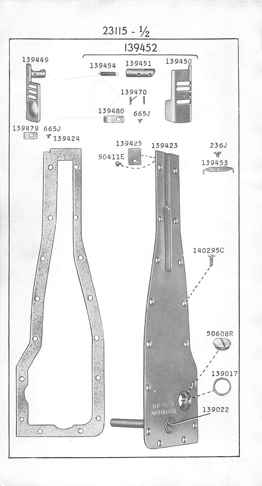
 139431 23116 \" \" \" \" Oil Retalner(leather) 139432 23116 \" Lifting Eccentric Forked Connection 139433 23113 Looper (back) 139434")
36 NUMERICAL LIST OF PARTS 35 No. Plate Name Feed Bar " " Hinge Pin (eccentric) " " " " Oil Retalner(leather) " Lifting Eccentric Forked Connection Looper (back) " (front) Note: When ordering Loopers, state gauge required Looper Avoiding Eccentric Forked Connec tion with 1057AL Looper Avoiding Eccentric Forked Connec tion Shaft Looper Avoiding Eccentric Forked Connec tion Shaft Bracket with 456C Looper Driving Arm with 1047AL " " " Connection with and Looper Driving Arm Ball Screw Stud for Looper Driving Arm Ball Screw Stud Nut Lock Washer Looper Driving Arm Connection Crank with 1057AL, for Looper Driving Arm Hinge Stud " " " " " Cap Screw Washer (lead) Looper Eccentric and Feed Lifting Eccen tric with two 1036AL Looper Eccentric Connection with 1047AL " " " SUde Block Screw Stud Looper Eccentric Connection Slide Block Screw Stud Collar with two 1253AL Looper Gate (left) with 665J and " " (right) for " " " Hinge Stud Connection for Looper Gate (right) complete, Noe. 665J, ,139451,139454, and two Looper Gate Locking Plate " " Spring for " Holder with 586E, and 51485AL Looper Holder Shaft " " " Bushing (front) " Thread Guide Needle Guard, for 3/32 In. to 3/16 In. gauges Note: When ordering Needle Guards, state gaixge re quired.
37 36 NUMERICAL LIST OF PARTS No Plate l'^ Note: When quired C C C Name Throat Plate for , for 3/16 In. to 1/4 In. gauges Lap Seam Feller Slide Presser Bar " " Lifting Bracket with 1057AL. " " Spring Housing " " " Seat (lower) " " (upper) Looper Gate (right) Hinge Stud Connec tion Hinge Pin for Looper Gate Spring Position Pin for Throat Plate, for 13^86, for 5/32 In. gauge Throat Plate,for , for 1/8 In. and 5/32 in. gauges Bed Extension Belt Guard with two 146R, for and ,for use with Bed Extension No , for all applications except for oblique mounting of the Machine on Singer Universal Safety Power Tables Looper Gate (left) Lock Spring for Looper Gate (right) Lock Spring for Belt Guard with two wood screws 3/4 In. No. 9 R.H., for , for use with Bed Extension No , for use on Singer Universal Safety Power Tables when Machine Is set at an oblique angle Needle Gimrd for 7/32 in. and 1/4 in. gauges ordering Needle Guards, state gauge re- Starting Treadle Set Screw for (2) Starting Treadle Shaft Arm Set Screw for (2) Bed Cover Screw (16) Thread Unwinder Spool Rest Cushion (felt) for (4) Treadle Pitman Rod (upper) Spring for 69336
38 NUMERICAL LIST OF PARTS 37 No. Plate Name Foot Lifter Treadle for Starting Treadle Shaft Collar with two 4450, for Thread Unwinder Base with two 4370, for 15CS70 Thread unwinder Rod for " " Thread Oone Holder for (4) Thread Unwinder Thread Oone Holder Sup port for Thread Unwinder Thread Cone Steady Wire for (4) Thread Unwinder Thread Guide for Thread Unwinder complete, for Inverted cones (for four cones) Nos. 178J, 51082R,150364,150365,150367,150369, three wood screws 1 1/2 In, No. 16 F.H. and four each 164J,19020, and Idler Bracket with 144aAL, for " Pulley for " " Shaft for Arm Rotary Shaft Ball Bearing (back)... Bed Rotary Shaft Ball Bearing (right)... Idler Pulley Shaft Ball Bearing for Idler Pulley Shaft Ball Bearing Cover for Idler Pulley Shaft Ball Bearing Cover Gasket (cork) for '... Idler complete (adjacent to Balance Wheel) for and , Nos ,150480, and two 51183R. Starting Treadle with two , for * Starting Treadle Shaft for " " " Arm with two , for Starting Treadle Spacing Collar for Starting and Foot Lifter Treadle com plete for , and , Nos. 4879,6439,150212,150216, to and two Idler Pulley and Shaft complete for and , Nos. 144D, to and foiu* 330R Starting and Foot Lifter Treadle with Pitman complete for Universal Safety Power Tables for , Nos and
39 38 NUMERICAL LIST OF PARTS No. Plate F Bed C Bed C Arm C Bed Arm Bed Bed Name Starting and Foot Lifter Treadle with Pitman complete for Low Shaft Power Table for under Driver No , Nos and Idler Base with 356C, for " Pulley Shaft Bracket (lower) with 168C and 692C, for Idler Pulley Shaft Bracket (upper) with 168C and 692C, for Idler Pulley Shaft Bracket Shaft for 15(»32 Idler complete, for Under the Table, for Singer Universal Safety Power Table, Nos to , two and three wood screws 1 1/4 In. No. 12 F.H Idler Guard with two wood screws 3/4 In. No. 9 R.H., for Thread unwinder Spool Rest with 178J,for (4) Thread Unwinder Spool Rest Rod.for Thread Unwinder Spool Rests complete (for four spools) for use when Spools are used in place of Cones of Thread, for use with Thread Unwinder Nos , Nos. 178J, and four each and Power Table Accessories, for all styles of Electric Transmitter Power Tables Nos , and Power Table Accessories, for Universal Low Shaft Power Tables, Nos and Power Table Accessories for Universal Safety Power Tables, Nos and Belt Guard with two wood screws 1 In. No. 10 R.H. for Series S 39, S 49, S 59 and S 69 Electric Transmitters for Stand No , for use with Bed Extension No Rotary Shaft Belt Guard Cover Screw (2) Rotary Shaft Belt Guard Set Screw for (2) Rotary Shaft Sprocket Wheel Set Screw for (2) Rotary Shaft Sprocket Wheel Set Screw for (2) Rotary Shaft Sprocket Wheel Spring Flsuige for (2) Rotary Shaft Sprocket Wheel Spring Flange for

40 ILLUSTRATIONS OF PARTS
41 /2

42 /4 v%v

43 / isal 150U U R 15QU
44 Ye i51082r ;9 I506I17 178J

45 -I 1266AL o

46

47 AL 2C U9311 Ul III in. n. III. - 11(_ - HI - 11 I Ml. 506m U ^

48 W ^ 1390U Pn J p u3%6,732,y4''"

49 1392U =1 14= I392A _/ r VSf %2
50 /2

51 13Q E C57AL C15CAL 586C 896AL pC AL 51485AL ^ "' 443AL "9097^i E H AA3AL 152aJ AL 13943iy wiriinrixji. 1057AL jj '(J 1047AL C E 1095F 0^ ^ ^253AL AL' " C6lALyf^-,-j O 217J lo W w
52 I
53 624AL 15U7J 54C ) HOC flr J
54 / U ^ ki M J 54242

55

56 % mu3b

57 / R

58

59
Machine No. 62=53 LIST OF PARTS COMPLETE. Cp'2.- THE SINGER MANUFACTURING COMPANY. From the library of: Superior Sewing Machine & Supply LLC
 Cp'2.- e NUMIJEKINO DEPAilTMENT AuilEST 7, 1014 LIST OF PARTS COMPLETE A Machine No. 62=53 %= THE SINGER MANUFACTURING COMPANY iiv ^ --. : ' '', - - - -- W. ;.y -::- -^=v c v; > >,- -- ^/;c. V ^. r,.'
MACHINE PARTS CHART SINGER*
 Form U3174 (Rev. 983) Part No. 643197 002 (Rev. 1) MACHINE PARTS CHART for SINGER* 220 220 U2 U3 * A Trademark of THE SINGER COMPANY Copyright 1980 THE SINGER COMPANY All Rights Reserved Throughout the
1 ~::~, ~~/"' v -\ K 1' SINGER* G.,~ I ~ ~" ""cj. [E>~i 1241~ D200A ~\ c:? ""' B ~ ~
 SNGER* 431 D200A 544249 410672 505317-452 52454 ""cj 504094 ""', 410572-004 1 ::, 545901 549128...--- "''i:i K 1' 1241 549336 / 540549 /544980 t c:? 505151 505152 [E>i 504159-452 B--504083 ""' 0.;. ""'"
Singer From the library of: Superior Sewing Machine & Supply LLC
 Singer 69-14 LST OF PARTS COMPLETE NO. 69=14 MACHNE The Singer Manufacturing Co. ) LST OF PARTS COMPLETE FOR No. 69=14 Machine Central Bobbin, makes 18 staying and three fastening or tying stitches in
LIST PARTS. MAC~INE No. 410wl0 ** A TRACE MARK OF THE SINGER MANUFACTURING COMPANY. From the library of: Superior Sewing Machine & Supply LLC
 Form 3021w --- - -- -- (250) Printed in U. S. A. LIST OF PARTS MAC~INE No. 410wl0 ** A TRACE MARK OF THE SINGER MANUFACTURING COMPANY INSTRUCTIONS FOR OILING To ensure easy running and prevent unnecessary
SINGER 531B-8BL. From the library of: Superior Sewing Machine & Supply LLC
 SINGER 53B-8BL PERSPECTIVE THREAD TENSION, GUIDE, NEEDLE PLATE i SINGER 4 THREAD TENSION, GUIDE, NEEDLE PLATE 3 Fig. No. Parts No. Quantity Name of Parts Fig. No. Parts No. Quantity Name of Parts 0698
OPERATING INSTRUCTIONS 3421UX VETERANS BLVD, CARLSTADT, NJ 07072
 OPERATING INSTRUCTIONS 3421UX5-1 400 VETERANS BLVD, CARLSTADT, NJ 07072 CONTENTS DESCRIPTION... 3 OPERATOR INFORMATION... 5-8 INSTALLATION...... 4 ADJUSTMENT... 8-17 LUBRICATION... 5 INDEX Description
for SINGER Copyright :s: SINGER SEWING MACHINE COMPANY All Rights Reserved Throughout The World
 Form U6290 17931 Part No. 379453-002 Printed 1n Japan MACHINE PARTS CHART for SINGER 300U101A Copyright :s:- 1993 SINGER SEWING MACHINE COMPANY All Rights Reserved Throughout The World :"/UMERICAL LIST
From the library of: Superior Sewing Machine & Supply LLC
 1. Base plate, Handle, and Oil 'Wick.,... ' J 205-201-01 A 205-1-01C WS-01-~ 51-0002 --.205-14-01 --- WP-0501 Lsi-50001 2. Covers -05-0-01 A 205-0-00 205-0-00B From the library of: Superior Sewing 2 Machine
DT3-B291 Cylinder Bed Needle Feed Double Chain Stitcher
 DT3-B291 Cylinder Bed Needle Feed Double Chain Stitcher Specifications DT3 - B291-060 - No. of needles & Needle gauge 7 Twin needle, 31.8 mm (1 1/4) 8 Twin needle, 34.9 mm (1 3/8) A 4 needle, 6.4-25.4-6.4
PARTS LIST MODEL: HDEJ1800
 First Edition: June 0 PARTS LIST 0 8 4 8 8 4 8 0 KEY PARTS NO. NO. DESCRIPTION 0400 Top cover (unit) 00 Top cover (unit) 0000 Top cover 4 40A04 Flip-top sewing instruction panel 000 Hinge rod (right) 00
NEWLONG. r PORTABLE FILLED BAG CLOSING MACHINE NEWLONG MACHINE WORKS, LTD.
 NEWLONG r PORTABLE FILLED BAG CLOSING MACHINE * NEWLONG MACHINE WORKS, LTD. () THREAD TENSION AND COVER PARTS 0 () THREAD TENSION AND COVER PARTS Ref. No. Part No. Description Q ty Remarks 5 6 7 8 9 0
(251) Printed in U. S. A. LIST PARTS SINGER. MACHINE No. I68wl0l THE SINGER MANUFACTURING. *A Trade Mark of THESINGER MANUFACTURING COMPANY
 Printed in U. S. A. LIST PARTS SINGER. MACHINE No. I68wl0l THE SINGER MANUFACTURING. *A Trade Mark of THESINGER MANUFACTURING COMPANY") (251) Printed in U. S. A. LIST OF PARTS SINGER MACHINE No. I68wl0l THE SINGER MANUFACTURING COMPANV *A Trade Mark of THESINGER MANUFACTURING COMPANY y INSTRUCTIONS FOR OILING To ensure easy running and
(251) Printed in U. S. A. LIST OF PARTS SINGER MACHINE No. I68wl0l THE SINGER MANUFACTURING COMPANV *A Trade Mark of THESINGER MANUFACTURING COMPANY y INSTRUCTIONS FOR OILING To ensure easy running and
Y A O H A N MODEL ONE THREAD
 Y A O H A N MODEL ONE THREAD N00A( ) N0A( TWO THREAD ) ONE THREAD HIGH SPEED N00H( ) TWO THREAD HIGH SPEED N0H( ) P OR T A B L E B A G C L OS E R P A R T S B OOK Y AO HAN INDUS TR IE S C O., L TD. 00.0.
SINGER. PARTS LIST DEARBORN BLIND STITCH MACHINE MODEL 12 SS-1 SINGER COMPANY OF CANADA LIMITED
 SINGER. PARTS LIST DEARBORN BLIND STITCH MACHINE MODEL 12 SS1 SECTIONS MAIN SHAFT NEEDLE SHAFT FEED FRAME SWING PLATE SKIP CONTROL MACHINE GEAR ASSEMBLY LOOPER ROD REGULATING KNEE LIFT AND CRANK HEAD NEEDLE
STYLES 53700B 53800B ADJUSTING INSTRUCTIONS AND ILLUSTRATED PARTS LIST CATALOG NO. 100L-GR STREAMLINED FIFTY THOUSAND SERIES FIRST EDITION 01/23/09
 STYLES 53700B 53800B ADJUSTING INSTRUCTIONS AND ILLUSTRATED PARTS LIST STREAMLINED FIFTY THOUSAND SERIES CATALOG NO. 00L-GR FIRST EDITION 0/3/09 MANUAL NO. 00L-GR ADJUSTING INSTRUCTIONS AND LLUSTRATED
FBX1104P FBX1104 FBX1106P FBX1106
 FBX1104P FBX1104 FBX1106P FBX1106 Second edition : September 2004 No. 040037 INTRODUCTION Thank you for your purchasing Kansai Special's FBX Series. Read and study this instruction manual carefully before
LS2-B891 LT2-B892 LS2-B891-05, LT2-B892-05
 LS2-B891 LT2-B892 Single Needle Unison Feed Lock Stitcher Single Needle Unison Feed Lock Stitcher with Thread Trimmer Twin Needle Unison Feed Lock Stitcher Twin Needle Unison Feed Lock Stitcher with Thread
SERVICE MANUAL AND PARTSLIST
 SERVICE MANUAL AND PARTSLIST Next 20 CONTENTS WHAT TO DO WHEN... 1~3 SERVICE ACCESS FACE COVER... 4 TOP COVER... 4 BASE COVER... 5 REAR COVER... 6 FRONT COVER... 7 MECHANICAL ADJUSTMENT NEEDLE THREAD TENSION...
PARTS REFERENCE LIST MODEL: M929D
 Home Sewing Machine PARTS REFERENCE LIST MODEL: M929D CONTENTS (1) PRINCIPAL PARTS... 2 (2) NEEDLE BAR, FEED BAR AND PRESSER HOLDER... 4 (3) KNIFE AND LOOPER... 6 (4) LAMP, MOTOR AND ACCESSORY... 8-1 -
INSTRUCTIONS and PARTS BOOK. U. S. Blind Stitch Machines
 r- INSTRUCTIONS and PARTS BOOK for U. S. Blind Stitch Machines Model 88-R. S. BLIND STITCH MACHINE CORP. 12 SEVENTH AVENUE NEW YORK 1, N. Y. LAclcawanna 4-9144-5-6 A SUPPLEMENT TO PARTS CATALOGUE FOR U.S.
CONTENTS (1) PRINCIPAL PARTS... 2 (2) UPPER SHAFT, NEEDLE BAR AND FEED MECHANISM... 4 (3) SHUTTLE HOOK, BH AND FEED ADJUST MECHANISM...
 PRINCIPAL PARTS... 2 (2) UPPER SHAFT, NEEDLE BAR AND FEED MECHANISM... 4 (3) SHUTTLE HOOK, BH AND FEED ADJUST MECHANISM...") 11.1999. CONTENTS (1) PRINCIPAL PARTS... 2 (2) UPPER SHAFT, NEEDLE BAR AND FEED MECHANISM... 4 (3) SHUTTLE HOOK, BH AND FEED ADJUST MECHANISM... 8 (4) PATTERN SELECTION MECHANISM... 10 (5) LAMP, THREAD
11.1999. CONTENTS (1) PRINCIPAL PARTS... 2 (2) UPPER SHAFT, NEEDLE BAR AND FEED MECHANISM... 4 (3) SHUTTLE HOOK, BH AND FEED ADJUST MECHANISM... 8 (4) PATTERN SELECTION MECHANISM... 10 (5) LAMP, THREAD
PARTS LIST MODEL DC4100
 MODEL DC0 0 0 MODEL DC 0 KEY 0 0 PARTS 00 000 00000 000 00 0000 00000 000 00 0000 000 00 000 00000 000 000 000 000 000 0 00000 0 0000 0 0000 000 0000 00 00000 0000 0 0000 00000 00 00 00000 00000 0000 DESCRIPTION
WX8800 WX8700 LX5801 WX8842 WX MC30
 WX8800 WX8700 LX5801 WX8842 WX8842-1 MC30 First published : August 1991 Third edition : August 2004 No. 040037 INTRODUCTION Thank you for your purchasing Kansai Special's WX Series. Read and study this
SERVICE MANUAL. Sewing Machine. Copyright 1976 The Singer Company Aii Rights Reserved Throughout the World *A Trademark of THE SiNGER COMPANY
 1 SERVICE MANUAL SINGER Sewing Machine 121D200A Copyright 1976 The Singer Company Aii Rights Reserved Throughout the World *A Trademark of THE SiNGER COMPANY Form 21624 (876) Printed In U.S.A. LUBRICATION
TZl Please clarify Ref. No. and Parts No. as well as parts name When you place an order.
 II -. TZl-.865.2 /...._J..... "Ill -.. Please clarify Ref. No. and Parts No. as well as parts name When you place an order.... ~.. Ref. No. N arne of Parts Part No. Ref. No. N arne of Parts Part No. 1
SERVICING MANUAL 419S/423S
 SERVICING MANUAL 415 419S/423S TROUBLESHOOTING PROBLEM CAUSE REMEDY REFERENCE 1. SKIPPING 1. NEEDLE IS NOT INSERTED INSERT THE NEEDLE PROPERLY. STITCHES PROPERLY. 2. NEEDLE IS BENT OR WORN. CHANGE THE
FBX-PA-2AC. Third edition : April No
 FBX-PA-2AC Third edition : April 2006 No. 060058 INTRODUCTION Thank you very much for purchasing Kansai Special FBX series. Read and study this Instruction Manual carefully before you start any of the
INSTRUCTION. Industrial Sewing Machines V7100/D,DE,F,ML W8100/D,DE,F,C W8042 W V7002-1S W8103-1S. No Third edition : March 2001
 INSTRUCTION Industrial Sewing Machines V7100/D,DE,F,ML W8100/D,DE,F,C W8042 W8042-1 V7002-1S W8103-1S Third edition : March 2001 No. 010012 INTRODUCTION Thank you for your purchasing Kansai Special's V.W
LONSEW. model. en 2230 R LIST OPERATING ~IONS' P~RTS CONSOLIDATED SEWING MACHINE CORP. COP RIGHT 1989 CONSOLIDATED SEWING MACHINE CORPORATION
 / OPERATING ~IONS' P~RTS LIST LONSEW CONSOLIDATED SEWING MACHINE CORP. model en 2230 R CONSOLIDATED SEWING MACHINE CORP. COP RIGHT 1989 CONSOLIDATED SEWING MACHINE CORPORATION SPECIFICATIONS -CON SEW Model
YAO HAN 耀瀚股份有限公司 YA O H A N I N D U S T R I E S C O., LT D. 手提式縫口袋機 YA O H A N I N D U S T R I E S C O., LT D.
 耀瀚股份有限公司 YA O H A N I N D U S T R I E S C O., LT D. YAO HAN MODEL ONE THREAD F300A ( 單線 ) TWO THREAD F302A ( 雙線 ) 手提式縫口袋機 PORTABLE BAG CLOSER PARTS BOOK 零件本 2005.09.26 耀瀚股份有限公司 YA O H A N I N D U S T R
INSTRUCTION BX1425P,PSM,PTV BX1433P,PSM,PTV BX1025P,PSM BX1033P,PSM. No First published : November 1997
 INSTRUCTION Industrial Sewing Machines BX1425P,PSM,PTV BX1433P,PSM,PTV BX1025P,PSM BX1033P,PSM First published : November 1997 No. 970112 INTRODUCTION Thank you for your purchasing Kansai Special's BX
First published : May 1997 Fourth edition : January No
 First published : May 1997 Fourth edition : January 2006 No. 050153 INTRODUCTION Thank you for your purchasing Kansai Special's FX Series. Read and study this instruction manual carefully before beginning
PARTS LIST. SCHflSSs. Nos. 133w102 and 133w 103 A/^CHINES THE SINGER MANUFACTURING COMPANY. From the library of: Superior Sewing Machine & Supply LLC
 Forir 2787w (841 ) Printed, in U. Sr-A. LIST OF PARTS SCHflSSs A/^CHINES Nos. 133w102 and 133w 103 THE SINGER MANUFACTURING COMPANY Copyright, U. S. A., 1938, 1939, 1940 and 1941 by Tho Singer Manufacturing
SINGER SERVICE MANUAL. Class 261. r; ; THE SINGER COMPANY
 -Jfit Form IPD 436-71 (Supersedes Form 21189) SINGER o I SERVICE MANUAL Class 261 r; ; -.. ; H -7-5 ^. *A Trodtmark of THE SINGER COMPANY THE SINGER COMPANY Copyright 1963 by The Singer Company Copyright
16U288 SINGER' SEWING MACHINE. From the library of: Superior I Sewing Machine & Supply LLC INSTRUCTIONS. Form UIO3 (Rev, 377)., THE SINGER COMPANY
., THE SINGER COMPANY") iiv^- Form UIO3 (Rev, 377)., INSTRUCTIONS FOR USING AND ADJUSTING SINGER' SEWING MACHINE 16U288 THE SINGER COMPANY From the library of: Superior I Sewing Machine & Supply LLC CONTENTS PAGE DESCRIPTION
iiv^- Form UIO3 (Rev, 377)., INSTRUCTIONS FOR USING AND ADJUSTING SINGER' SEWING MACHINE 16U288 THE SINGER COMPANY From the library of: Superior I Sewing Machine & Supply LLC CONTENTS PAGE DESCRIPTION
ADJUSTING INSTRUCTIONS / ILLUSTRATED PARTS LIST
 ADJUSTING INSTRUCTIONS / ILLUSTRATED PARTS LIST 35800 High Speed Feed- Off- The- Arm With Plain Feed Differential Feed MANUAL NO. PT060-GR STYLES 35800BLWG 35800BQWG 35800BWDNG 35800BWDRG 35800BWWG 35800BWWPG
Di-Acro 18E Stylus Turret Punch Press
 OPERATOR S MANUAL & INSTRUCTIONS Di-Acro E Stylus Turret Punch Press Di-Acro, Incorporated PO Box 00 Canton, Ohio Progress Street N.E. Canton, Ohio 0 0-- 0--00 (fax) Revised 0/0 Sale or distribution of
SERVICE MANUAL PARTS LIST MODEL: NH40
 SERVICE MANUAL & PARTS LIST MODEL: NH40 CONTENTS What to do when... 1-3 SERVICE ACCESS Face Cover... 4 Bed Cover... 5 Free-arm Cover... 6 Front Cover... 7 Rear Cover... 8 MECHANICAL ADJUSTMENT Presser
 488 PARTS LIST 1 3 SCREWS FOR NO. 2 2 FLYWHEEL CAP 3 FLYWHEEL 4 END NUT FOR NO. 10 5 BALL BEARING FOR NO. 3 (1 st ) 6 BALLBEARING FOR NO. 3 (2nd) 7A CLUTCH RACE KEY 7B CLUTCH RACE 7C CLUTCH SPRING 7D 7
MITSUBISHI SEWING MACHINE PARTS CATALOG
 From the library of: Superior Sewing Machine & Supply LLC V \ V. 3 ) MITSUBISHI SEWING MACHINE PARTS CATALOG Model DH-400 INDEX 1. 2^ b!5 pp Arm bed & its accessories V40-1 2. ±.$4, Upper shaft & needle
MODEL RA-200N RADIAL ARM SAW
 ITEM NO PART NO DESCRIPTION PRICE 1 6130089 HEX. NUT (L.H.T.) W5/8"-18UNF 2.18 2 6900079 CONICAL SPRING 16.3 X 31.5 X 1.2 0.78 3 6940444 OUTER FLANGE 4.49 4 6940443 INNER FLANGE 4.91 5 6100509 PARALLEL
MF-7524 INSTRUCTION MANUAL
 MF-7524 INSTRUCTION MANUAL 1 CONTENTS Ⅰ. SPECIFICATIONS...1 Ⅱ. CONFIGURATION OF THE MACHINE COMPONENTS...2 Ⅲ. INSTALLATION... 3 1. Installing the machine head onto the table...3 2. Selecting the motor
PARTS CATALOGUE FOR PROFESSIONAL EMBROIDERY MACHINE PR600 PR600C
 PARTS CATALOGUE FOR PROFESSIONAL EMBROIDERY MACHINE PR600 PR600C 10. 2003. CONTENTS (1) PRINCIPAL PARTS... 2 (2) UPPER SHAFT MECHANISM... 4 (3) NEEDLE BAR MECHANISM... 6 (4) NEEDLE BAR CHANGE MECHANISM...
Number Wheeler P/N Description Set Rex P/N Notes Base 1 J Support, Right 1 J Support, Left 1 J Nut (M8)
") 1 603500 Base 1 J001 2 603501 Support, Right 1 J002 3 603502 Support, Left 1 J003 4 600328 Nut (M8) 4 5 600130 Spring Washer (8mm) 4 6 600344 Roll Pin (M6x30) 4 7 600129 Socket Hd Cap Screw (M8x25) 4 8
1 603500 Base 1 J001 2 603501 Support, Right 1 J002 3 603502 Support, Left 1 J003 4 600328 Nut (M8) 4 5 600130 Spring Washer (8mm) 4 6 600344 Roll Pin (M6x30) 4 7 600129 Socket Hd Cap Screw (M8x25) 4 8
Headstock Gear System
 Headstock Gear System (0000 Series Parts) 10 7 6 5 4 3, 2 16 11 12 13 14 15 9,8 1 90 17 18 19 20 21 22 23 24 25 26 27 28 29 30 31 32 33 34 91 93 94 95 96 97 98 99 100 102 104 106 108 109 92 101 103 105
Section A Gear Box September A
 Section A Gear Box September 06 1A Index 1. 1-10016-000 Gear Box Oil Pan. 1-100486-000 Clutch Lever Assembly, See Page 9A for breakdown. 1-1004-000 Clutch Cam, for all A machines prior to Serial #5 1-104-000
SERVICE MANUAL FOR DT4-B281 FOUR NEEDLE DOUBLE CHAIN STITCHER WITH PULLER. From the library of: Superior Sewing Machine & Supply LLC
 SERVICE MANUAL FOR DT4-B281 FOUR NEEDLE DOUBLE CHAIN STITCHER WITH PULLER Table of Contents [A] Model Plate Display... 1 [B] Specifications... 2 [C] Description of Mechanism... 3 [) Needle bar mechanism...
INSTRUCTIONS and PARTS BOOK for U.S. MACHINES
 NSTRUCTONS and PARTS BOOK for U.S. MACHNES BASC and SPECAL PARTS for All SKP STTCH MODELS SUCH AS: 18,18-1,1 18, 118-1, 58, 58-1, 58-C, 58-K 518, 518-1, 518-2, 518-9, 518-A, 518-C, 518-PR, 5 18-PRB U.
SECTION 9: PARTS. Table Breakdown REF PART # DESCRIPTION REF PART # DESCRIPTION
 SECTION 9: PARTS Table Breakdown 1 2 3 4 5 6 7 8 9 10 11 12 13 14 15 16 17 18 19 20 21 22 23 24 23 25 17 26 27 8 1 P0675001 CAP SCREW M8-1.25 X 30 15 P0675015 SUPPORT BLOCK 2 P0675002 TABLE SUPPORT BLOCK
535A. Main Components. Pipe and Bolt Threading Machine. Printed in U.S.A. Ridge Tool Company/Elyria, Ohio, U.S.A.
 Pipe and Bolt Threading Machine A Main Components 0 Screw, Button Head /" - 0 x /" () Washer, Flat /" ()" Top Cover 0 Base Bottom Cover Screw, Pan Head # - x " () Carriage Assembly 0 Front Support Bar
Inspection. Assembly Install the springs. 1. Discard the 0-rings. 2. Clean all parts in cleaning solvent.
 6010-34 Inspection 3. Install the springs. 1. Discard the 0-rings. 2. Clean all parts in cleaning solvent. 3. If spring test equipment is available, check the tension of each spring according to the specifications
PFAFF. rom the library of: Superior Sewing Machine & Supply LLC. Service Manual Justieranl. engi. 7.92
 PFAFF 5642 Service Manual 296-12-13925 Justieranl. engi. 7.92 Notes on safety The machine must only be commissioned in full knowledge of the instruction book and operated by persons with appropriate training.
CONTENTS PRECAUTIONS BEFORE STARTING OPERATION PREPARATION FOR OPERATION CAUTIONS ON USE OPERATION
 CONTENTS PRECAUTIONS BEFORE STARTING OPERATION ------------------------------------- 1 PREPARATION FOR OPERATION 1. Adjustment of needle bar stop position ---------------------------------------------------------
1822-I. Spindle Assembly. Pipe and Bolt Threading Machine. Ridge Tool Company/Elyria, Ohio, U.S.A. 2* 3 4 5* * *
 -I Pipe and Bolt Threading Machine Spindle Assembly * * * 0 * * * 0 * * 0* * * Rear Cover * Screw () * Washer () Top Cover w/clips (Includes,, ) * J Clip () Front Cover * Screw () Pivot Rod Support ()
SINGER 591D200A 591D240A 591D303A 591D305A 591C308A. rom the library of: Superior Sewing Machine & Supply LLC 591D300A
 SINGER 591D200A 591D240A 591D300A 591D303A 591D305A 591D308A 591C200A 591C240A 591C300A 591C308A CONTENTS Page Introducingtlie NewSINGER* Sewing Machine Model 591 \ Oiling the Machine 2 Oiling the Puller
UK10 UK11. First published: June No.KX03023
 UK10 UK11 First published: June 2003 No.KX03023 INTRODUCTION Thank you for purchasing Kansai Special s UK series machine. Please study this instruction manual carefully before operating the machine. 1.
RYOBI 10 IN (254 MM) TABLE SAW MODEL NO. BT REPAIR SHEET
 TABLE SAW MODEL NO. BT REPAIR SHEET") RYOBI 0 IN (2 MM) TABLE SAW MODEL NO. BT00- REPAIR SHEET 2 RYOBI 0 in. (2 mm) TABLE SAW - MODEL NO. BT00- FOR MITER TABLE ASSEMBLY, REFER TO FIGURE B FOR BLADE GUARD ASSEMBLY, REFER TO FIGURE E FOR RIP
RYOBI 0 IN (2 MM) TABLE SAW MODEL NO. BT00- REPAIR SHEET 2 RYOBI 0 in. (2 mm) TABLE SAW - MODEL NO. BT00- FOR MITER TABLE ASSEMBLY, REFER TO FIGURE B FOR BLADE GUARD ASSEMBLY, REFER TO FIGURE E FOR RIP
LEWIS. PARTS and INSTRUCTIONS. 150 Class Machines. ll/j"zu.m.jl;.ic.c:':i.q.:. MACHINE COMPANY. Catalogue Models
 LEWIS PARTS and INSTRUCTIONS Catalogue 194-5 150 Class Machines Models 150-1 150-5 150-6 150-6TS 150-7 150-9 150-15 150-16 150-17 150-20 150-23 PRODUCT OF ll/j"zu.m.jl;.ic.c:':i.q.:. MACHINE COMPANY 400
PARTS REFERENCE LIST MODEL: BLDC2 BL200A
 Home Sewing Machine PARTS REFERENCE LIST MODEL: BLDC2 BL200A CONTENTS (1) PRINCIPAL PARTS... 2 (2) UPPER SHAFT / NEEDLE BAR, PRESSER MECHANISM... 4 (3) FEED, ROTARY HOOK / THREAD CUTTING MECHANISM... 6
Exploded View Saw Base - Model 7060 Semi-Automatic Cut-Off Band Saw
 Exploded View Saw Base - Model 7060 Semi-Automatic Cut-Off Band Saw 136 137 135 134 132 131 133 113 114 115 117 116 118 119 120 121 79 78 77 107 108 65 76 110 109 66 10 9 6 11 5 4 8 7 75 74 73 72 111 112
Coolant Tank Screen Leg Idle End Lockwasher 64 B-015B Leg Drive End Machine Screw 1/4-20 x 3/4 Round Head
 Always give model number, serial number and part number when ordering repair parts. BED, COOLANT & DASH POT PARTS LIST (Cont'd.) REF NO. PART NUMBER DESCRIPTION 19 B-077 Vise Slide Block 20 B-045 Vise
/ ' r V SERVICE MANUAL FOR SINGER SEWING MACHINES 211G G156 THE SINGER COMPANY. From the library of: Superior Sewing Machine & Supply LLC
 / ' r V SERVICE MANUAL FOR SINGER SEWING MACHINES 211G 155 211 G156 THE SINGER COMPANY CONTENTS Page Description 3 Speed 3 Installation of the machine 4 Lubrication 4 Needles 5 Thread 5 Bobbin removal
PARTS REFERENCE LIST MODEL: 2340CV
 Home Sewing Machine PARTS REFERENCE LIST MODEL: 2340CV Published: Sep.,2003 Revised: Mar.,2014 MODEL LIST Model Countries (Added Date) 2340CV CAN, GUF (Apr / 2011) 2340CV MYS (May / 2011) 2340CV HKG (Mar
RYOBI 10 in. (254 mm) TABLE SAW MODEL NO. BT3100 REPAIR SHEET
 TABLE SAW MODEL NO. BT3100 REPAIR SHEET") RYOBI 0 in. (4 mm) TABLE SAW MODEL NO. BT00 REPAIR SHEET FOR MITER TABLE ASSEMBLY, REFER TO FIGURE B FOR BLADE GUARD ASSEMBLY, REFER TO FIGURE E FOR RIP FENCE ASSEMBLY, REFER TO FIGURE C FOR MOTOR ASSEMBLY,
RYOBI 0 in. (4 mm) TABLE SAW MODEL NO. BT00 REPAIR SHEET FOR MITER TABLE ASSEMBLY, REFER TO FIGURE B FOR BLADE GUARD ASSEMBLY, REFER TO FIGURE E FOR RIP FENCE ASSEMBLY, REFER TO FIGURE C FOR MOTOR ASSEMBLY,
DB Four Needle Double Chain stitcher. Specifications. 4 needles. *A needle gauge for 60 is U1401 only. DB /
 DB-2810 Four Needle Double Chain stitcher Specifications 4 needles A Specifications No. needle of No of thread Needle size (UY113GS) Max. stitch length (mm) Height of presser foot (mm) Max. sewing speed
MODEL RA-2500N RADIAL ARM SAW
 1 6130089 HEX. NUT (L.H.T.) W5/8"-18UNF 2.18 2 6900549 WASHER 1.78 3 6080529 ARBOR COLLAR 31.02 4 6760117 OILLESS METAL 1.57 5 9270612 CLAMP SCREW M6 X 12 0.19 6 9220625 HEX. SOCKET HEAD BOLT M6 X 25 0.22
From the library of: Superior Sewing Machine & Supply LLC
 SEIKO {( im (B JP M t O ^ mid jmt ^ IO JES JLi X) 2n> ^ ^ ^ ^ ^ ^ SSlSiD STSRM SlUMRSS 1? /tf SPECIFICATIONS Maximum speed: Number of needle : Needle: Thread: Feed : Stitch: Presser foot: Presser bar lift:
PARTS LIST COMMANDER 20 VAC-TRAC COMMANDER 27 VAC-TRAC FH 541V
 PARTS LIST COMMANDER 20 VAC-TRAC COMMANDER 27 VAC-TRAC FH 541V UPPER ASSEMBLY 101 6190481 THROTTLE CABLE FOR MODELS WITH ADDITIONAL CHOKE CABLE 1 101 6190751 THROTTLE CABLE FOR MODELS WITH OUT ADDITIONAL
HYDRAULIC CONTROL DETAILS PARTS LIST
 Always give model number, serial number and part number when ordering repair parts. HYDRAULIC CONTROL DETAILS PARTS LIST REF NO. PART NUMBER DESCRIPTION 1 101939 Hydraulic Tank 2 101940 Hydraulic Tank
t..j; ::.:~f"", ~ ~,r>:. f-.~ ~ r'o.f"<.. "
 _. De~artmet 154 tj; ::.:~f, ~ ~,r>:. f-.~ ~ r'o.f< : ~ --'.: :. ~.,.,J :.,! ~ ~,. \. ~', r-' f ' - - --.: -.- ----. List of Parts Complete for MacbLe Ho. 109-721 VS:C August 19, 1947 Departmet 154 Bo.
GRAND PIANO HARDWARE AND ACCESSORIES
 GRAND PIANO HARDWARE AND ACCESSORIES LID SUPPORT CUP No. 938 - Solid brass. Each No. 938N - Nickel plated. Each GRAND RAIL PROP NUTS Slotted grand rail prop nuts for replacement. Solid Brass. No. 925 -
ENGLISH MF-7500 INSTRUCTION MANUAL
 ENGLISH MF-7500 INSTRUCTION MANUAL i CONTENTS Ⅰ. SPECIFICATIONS...1 Ⅱ. CONFIGURATION OF THE MACHINE COMPONENTS...2 Ⅲ. INSTALLATION...3 1. Installing the machine head onto the table... 3 2. Selecting the
MACHINE COMPANY. From the library of: Superior Sewing Machine & Supply LLC. 17 and T194-8 CLASSES LIST OF PARTS F OR
 INDUSTRIAL FINEST QUALITY LEWIS COLUMBIA SEWING MACHINES CLASSES 17 and 24 LIST OF PARTS F OR 17-100 17-130 24-120 24-130 CATALOG NO. T194-8 CHICAGO MACHINE COMPANY Catalog Noo T194-8 LIST OF PARTS Styles
ST1014 PARTS ST1014 Headstock Breakdown
 ST1014 PARTS ST1014 Headstock Breakdown 112 114 23 104 105 108 102 106 20 19 21 22 101 100 103 111 38 14 15 37 46 44 47 45 107 93 39 41 40 67 110 109 74 75 76 11 12 13 9 8 6 10 31-2 31-3 3 2 7 26 24 31-1
Parts list. From Product number xx MARCH SVP Worldwide - All rights reserved.
 Parts list 01 SVP Worldwide - All rights reserved. From Product number 971-xx 0 MARCH 01 A 1 9 7 8 10 1 11 1 1 1 19 18 17 1 0 1 1 7 8 0 1 1 9 1 19810 PRE -TENSION UNIT 17901 REEL PIN 1701 SPRING, REEL
3000, 4000, 4100, 7500, 7700
 3000, 4000, 4100, 7500, 7700 Drum & Disc Brake Lathes s Identification READ these instructions before placing unit in service. KEEP these and other materials delivered with the unit in a binder near the
Operation and Maintenance Instructions Geared Head Bench Lathe Models GHB-1340A, GHB-1440A
 Operation and Maintenance Instructions Geared Head Bench Lathe Models GHB-1340A, GHB-1440A (GHB-1340A shown with optional stand 321443AK) For Parts List and Electrical Diagrams, see document M-321357A
Model No: TC10. Parts Information: Tyre Changer - Automatic
 Page 1 of 11 1 TC10.01 BODY 2 TC10.02 COLUMN 3 TC10.03 HORIZONTAL ARM ASS'Y 4 TC10.04 WASHER 5 TC10.05 RUBBER FOOT 6 TC10.06 COVER 7 TC10.07 SCREW M14x42 8 TC10.08 PRESS COVER 9 TC10.09 STOP-UP 10 TC10.10
25-200H. 12 Planer / Jointer. with Helical Cutterhead. Parts List.
 25-200H 12 Planer / Jointer with Helical Cutterhead 4001824 Parts List www.rikontools.com CABINET ASSEMBLY PARTS EXPLOSION & PARTS LIST KEY NO. DESCRIPTION KEY NO. DESCRIPTION 1 Pan Head Screw M6x12 P25-200H-1
PARTS G9729 Lathe Bed
 PARTS G9729 Lathe Bed 114 132 126 125 131 133 129 128 130 127 139 124 10 124 123 122 135 137 147 144 121 148 146 149 136 138 140 150 152 142 143 141 151 153 21 168 20 19 18 17 162 22 147 13315 14 13131
Operating Instructions and Parts Manual. 10 x 16 Horizontal Band Saw Models J-7020, J-7040
 Operating Instructions and Parts Manual 10 x 16 Horizontal Band Saw Models J-7020, J-7040 JET 427 New Sanford Road LaVergne, Tennessee 37086 Part No. M-414472 Ph.: 800-274-6848 Revision C2 03/2014 www.jettools.com
Parts List for Type 1
 1 422190430001 FENCE BODY 1 2 901010600677 CAP SCREW 2 3 904010331451 WASHER 3 4 901010600605 CAP SCREW 2 5 904010101604S STEEL WASHER 2 6 422040105002 REAR SLIDE BLOCK 1 7 905040714459 STEEL PIN 1 8 928010414118
1 OF 6 SPECIAL MACHINES
 1 OF 6 SPECIAL MACHINES 72000008 SIGHT FEED OILER NOS 16 "PART NO. 666-79,FOR STITCHING" MACHINE MODEL 72000012 LOOPER ROCKER CONNECTING NOS 20 BALL JOINT ASSEMBLY 72000013 PRESSURE FOOT ASSEMBLY PART
Parts List: Head Assembly
 Head Assembly 23 Parts List: Head Assembly Index No. Part No. Description Size Qty 1...JWP15H-001... Head Casting......1 2...TS-1525021... Set Screw... M10x12...8...JWP15DX-CA... Cutter Head Assembly (Index
SECTION 9: PARTS. Headstock A 126A 127A-1 REF PART # DESCRIPTION REF PART # DESCRIPTION
 SECTION 9: PARTS Headstock 120 121 113 115 112 111 110 109 108 105 106 107 135 101 119A 121 120 118 114 115 107 106 104 123 122 118 114 126A 105 126 103 102 126B 127A-1 131 127A 124 133 134 126C 129 130
Page 1 Parts List for AL-51G (L160) 07/08/201. Headstock Assembly
 07/08/201. Headstock Assembly") Page 1 Parts List for AL-51G (L160) 07/08/201 Headstock Assembly 1--------1002-------------------Headstock Casting 13-------1012------------------------------Nut M28 2--------1006---------------------------Flange
Page 1 Parts List for AL-51G (L160) 07/08/201 Headstock Assembly 1--------1002-------------------Headstock Casting 13-------1012------------------------------Nut M28 2--------1006---------------------------Flange
SPARE PARTS LIST MODEL NO. LB1200F PAGE 1 ITEM PART NO. DESCRIPTION QTY NOTE
 PAGE 1 001 JM21000018 HEX.SOCKET HEAD SCREW M5X12 4 002 JM21000019 SPRING WASHER 5 4 003 JM21000020 FLAT WASHER 5 4 004 JM21000021 UP COVER COMPLETE 1 005 JM21000025 MICRO SWITCH FIX PANEL A 1 006 JM21000026
Singer From the library of: Superior Sewing Machine & Supply LLC
 Siger 146-80 , i 1 1r:, rt:~ll' ::! l --~~,.. r~y Ji ~-'''~.._.- ~.- r DO NOT REMOVE OCTOBER 17, 1951. Ffill. MOOS llnlt LST OF PARTS COMPLETE FOR t' 7r:~. ALS1S October 17, 1951 Departmet #54 List of
OPERATION & MAINTENANCE MANUAL
 OPERATION & MAINTENANCE MANUAL AUTOMATIC PECAN CRACKER Food Processing Equipment and Machinery Specializing in the Pecan Industry Mailing: PO Box 817, Mansfield, Louisiana 71052 Located: 280 Independence
CONSOLIDATED SEWING MACHINE CORP. I.. INDUSTRIAL SEWING & CUTTING EQUIPMENT. Model 106R INSTRUCTION MANUAL & PARTS BOOK
 CONSOLDATED SEWNG MACHNE CORP... NDUSTRAL SEWNG & CUTTNG EQUPMENT Model 06R NSTRUCTON MANUAL & PARTS BOOK Table of Contents. ntroduction.... 2. Main specifications.... 3. nstallation and preparation....
Parts Catalog Admiral 28 Cylindrical Scrubber
 Parts Catalog Table of Contents Front bounce protection (97116834)... 4 Wheel suspension (97103725)... 6 Chassis (97115422)... 8 (97114763)... 10 Steering (97073738)... 12 Seat bracket (97118616)... 14
CATALOG OF REPLACEMENT PARTS
 The Choice of Experience CATALOG OF REPLACEMENT PARTS MODELS 909A 919A 909E 919E 909M 919M SLICERS EFFECTIVE MARCH 2009 - 2 - Table of Contents 5 ELECTRICAL COMPONENTS (909A & 919A) 7 ELECTRICAL COMPONENTS
STARTING SERIAL NUMBER PARTS LIST FOR. Wellsaw MODEL 600 METAL CUTTING BAND SAW
 STARTING SERIAL NUMBER 11075 PARTS LIST FOR Wellsaw MODEL 600 METAL CUTTING BAND SAW Wellsaw 2829 N. Burdick, Kalamazoo, MI 49004 Phone: 269-345-1132 Fax: 269-345-0095 Rev 171005 INSTALLATION, OPERATION
SERVICE MANUAL & PARTS LIST MODEL: MC400E
 First Edition: February SERVICE MANUAL & PARTS LIST MODEL: MC00E PARTS LIST MODEL: MC00E 0 0 MODEL: MC00E KEY PARTS NO. NO. DESCRIPTION 0 0 0B0 000 0A0 0A0 000 000 0 000 0 0000 0000 000 00 0 0 00 A0 0B0
MF-7000 Series 2-3 Needle Cylinder Bed Coverseam Machine
 R 2-3 Needle Flat Bed Coverseam Machine MF-7000 Series 2-3 Needle Cylinder Bed Coverseam Machine MFC-7000 Series ENGINEER S MANUAL 29275609 No.02 PREFACE This Engineer s Manual is written for the technical
U.ii.BUNDiSTITCH MACHINE CORP. EXPRESS STREET & SKYLINE DRIVE PLAINVIEW N.Y. U803
 U.ii.BUNDiSTITCH MACHINE CORP. EXPRESS STREET & SKYLINE DRIVE PLAINVIEW N.Y. U803 TELEPHONE: 516-433-4350 CABLE ADDRESS:"BLINSTIT PLAINVIEW NEW YORK" EST.1925 INSTALLATION AND OPERATING INSTRUCTIONS MAINTENANCE
READ THIS FIRST. For questions or help with this product contact Tech Support at (570) or
 or") READ THIS FIRST Models G0453, G0453Z, G0454, G0454Z ***IMPORTANT UPDATE*** For Machines Mfd. Since 09/17 and Owner's Manuals Revised 11/12 For questions or help with this product contact Tech Support at
READ THIS FIRST Models G0453, G0453Z, G0454, G0454Z ***IMPORTANT UPDATE*** For Machines Mfd. Since 09/17 and Owner's Manuals Revised 11/12 For questions or help with this product contact Tech Support at
S-85SCH
 4411-4423-4432-4443-4452 5511-5523-5532-5554 44S-85SCH Service Manual 104 73 14-26 2014-02-24 CONTENTS 1. Names of principal parts...2 2. Removing methods of external parts 2-1 Sewing table...3 2-2 Face
Brother Industries, Ltd. Nagoya, Japan
 4. 2001. This service manual has been compiled for explaining repair procedures of the MODEL XL-6562, XL6452, XR- 46. This was produced based on up-to-date product specifications at the time of issue,