Influence of Position Measurement on Accuracy in 5-Axis Machining
|
|
|
- Frederick Melton
- 5 years ago
- Views:
Transcription

1 Technical Information Influence of Position Measurement on Accuracy in 5-Axis Machining Productivity and accuracy are important attributes in the competition for machine tools. Five-axis machining provides considerable potential for increasing productivity. In many cases it permits higher metal removal rates than 3-axis machining. Production times can be significantly shortened thanks to a reduction of time required for resetting, for example, or through multi-operation machining in one setup. In any case, with increasingly complex workpiece geometry, 5-axis machining is becoming an indispensable part of the machining process. Since significantly larger traverse ranges of linear axes are usually required for 5-axis machining, machines need to provide high accuracy over the entire working space. Moreover, the two rotary axes in a 5-axis machine tool can greatly influence attainable workpiece accuracy. Besides the rotary axes, in most cases the linear axes must also be moved in order to change the orientation of the cutter to the workpiece surface. This can cause visible flaws in the traverse range of up to five axes within a small area of the workpiece surface. In 5-axis machining, precision-limiting effects in the drives, such as screw-pitch and transmission error, reversal error or thermally induced displacement can therefore much more quickly lead to the production of scrap. The positioning accuracy of linear and rotary axes play a decisive role here in the performance of a 5-axis machine tool. By now, 5-axis machining has become indispensable in many areas of metal-cutting machining. Clear economic advantages result from the capability to machine workpieces completely in one setup: the doorto-door time of a part can be dramatically reduced. At the same time, part accuracy can be significantly increased. Beyond this, the additional rotary axes allow better access to complex workpiece contours, for example cavities in dies or molds.often, they permit shorter tools with less inclination to chattering so that even higher metal removal rates are achieved. With 5-axis simultaneous machining, the cutting speed at the tool tooth can be held within narrow limits even on complex contours. This brings significant benefits with regard to the attainable surface quality. What is more, the use of highly productive tools (e.g. toroid cutters) when milling freeform contours would not be possible at all without 5-axis simultaneous machining.


2 Fields of Application for 5-Axis Machining Parts for Aeronautics and Space Industry High strength and low weight are essential for the aeronautics and space industry. Integral construction has established itself as the way to minimize the weight of airborne parts: components with complex structure are manufactured completely from a single blank. Metal removal levels can be as high as 95 %. This high buy-tofly rate leads to high costs for the raw material of the blanks. In the area of structural components, 5-axis machining opens new opportunities for reducing weight without loss of component strength. First, a computer-aided topology optimization is conducted that adapts the geometry of the component to the respective loads. The result: the material is brought specifically to where the mechanical load can be highest. In the other areas, material is specifically reduced. For example, the thickness of walls for stiffening can be easily adapted to the load distribution in the component. The wall thickness can decrease with increasing height, for example. This workpiece geometry can be realized in a simple way through 5-axis pocket milling. 5-axis machining in automobile manufacturing Uncounted molds and dies are needed in automobile manufacturing for sheet metal and plastic processing. Dies for sheet metal forming can be up to 6 m long and need to be milled at the very high accuracy of ± 0.02 mm so that the upper and bottom dies can work together with the correct gap. Moreover, a very high surface quality of all functional surfaces is necessary in order to ensure that the forming tools have a long service life. Five-axis machining in the field of medical technology In the field of medical technology, demand is high for devices that are adapted to special examinations or therapies. This can make treatments considerably more precise and reduce aftereffects on the patients. The devices are often characterized by very complex geometries that make 5-axis machining of single parts on milling machines attractive. Increasing life expectancy brings with it an increase in demand for tooth and joint implants. Today, hip and knee replacements offer many people the opportunity for a significantly better quality of life. In their external form, tooth and joint implants have to be perfectly fitted to the specific mating surfaces of a human body. Implants are mostly manufactured on milling machines, because milling makes even small batch sizes possible. Due to complex shaping of implants, medical technology is one of the largest fields of application for 5-axis machining. A prerequisite for the economical manufacturing of such sophisticated components is machines with high-accuracy position measurement for accurate and precise feed movements. Five-axis machining has long become the standard for the machining of jet engines. High efficiency requirements are driving continuous improvements in the flow characteristics of all jet engine components. The resulting component geometries are very complex and are therefore manufactured exclusively in 5-axis simultaneous milling movements. When manufacturing the tool contour, the machine has to maintain a very small distance between cutting paths in order to fulfill the requirements for high surface quality. This automatically lengthens the run times of the NC programs. The required accuracy of the forming tools is a formidable challenge for machine tools: high accuracy during long program run times on large components necessitates high thermal stability of the machine structure and the feed drives. Five-axis machining opens new perspectives for shortening machining times because even deeply curved contours of forming tools become more easily accessible. In addition, special tools such as toroid or radius cutters can be used that permit significantly larger path spacing and therefore reduce program run times. 2


3 Requirements of Position Measurement In 3 axis milling, the feed axes move within the dimensions of the workpiece plus the tool diameter. Unlike with 3-axis machining, in 5-axis machining the inclination of the tool can be adjusted with respect to the workpiece surface. If the position of the tool center point (TCP) remains unchanged, a change in the cutter orientation usually requires additional movement in the linear axes. These compensating movements necessarily increase the traverse range required by the linear axes. Because increasing traverse range also means increased positioning error, feed axes of 5-axis machines need significantly higher accuracy and reproducibility. The compensating movements of the linear axes are superimposed on the movements of the tool center commanded by the NC program in X, Y and Z. Due to this superimposition, the axis feed rates for the tool center can significantly exceed the programmed feed rate. The increase in feed velocity results in increased heat generation in the motors, transmission and recirculating ball screw. Depending on the principle of position measurement, the generation of heat can cause significant position error. To prevent faulty workpieces, precise position measurement in the feed axes directly at the moving machine elements is imperative. B A A: Traverse range with 3-axis machining B: Traverse range with 5-axis machining, incl. compensating movements 3
, then the ball screw must perform two tasks: As the drive system, it must transfer")

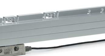
4 Position acquisition on linear axes The position of a feed axis can be measured either through the recirculating ball screw in combination with a rotary encoder, or through a linear encoder. If the axis position is determined from the pitch of the feed screw and a rotary encoder (see top illustration), then the ball screw must perform two tasks: As the drive system, it must transfer large forces, but as the measuring device it is expected to provide a highly accurate screw pitch. However, the position control loop only includes the rotary encoder. Because changes in the driving mechanics due to wear or temperature cannot be compensated in this way, this is called operating in a semi-closed loop. Positioning errors of the drives become unavoidable and can have a considerable influence on the quality of workpieces. As an alternative to using a recirculating ball screw, linear feed axes can also be driven by linear motors. In this case, the position of the machine axis is also measured directly by a linear encoder mounted on the axis slide. For highly dynamic and at the same time quiet operation, linear motors already depend on high-resolution, accurate linear encoders. For this type of drive, the advantages of closed-loop operation apply unrestrictedly. If a linear encoder is used for measurement of the slide position (middle illustration), the position control loop includes the complete feed mechanics. This is referred to as closed-loop operation. Play and inaccuracies in the transfer elements of the machine have no influence on position measurement. This means that the accuracy of the measurement depends almost solely on the precision and location of the linear encoder. Semi-closed loop: Position measurement of a linear axis by a rotary encoder in the feed motor Various conditions of application together with growing feed rates and forces lead to constant changes in the ball screw s thermal condition. Local temperature zones develop on a recirculating ball screw, which change with every change in position and decisively reduce accuracy in the semiclosed loop. High reproducibility and accuracy over the entire traverse range of linear axes can therefore be achieved only through operation in a closed loop. The results are precise workpieces and a drastically reduced rejection rate. Closed loop: Position measurement of a linear axis by a linear encoder 4 Thermographic image of a recirculating ball screw with increased temperature


5 Position acquisition on rotary axes The basic principle for linear axes also applies to rotary axes. Here, too, the position can be measured with a rotary encoder on the motor, or with a high-accuracy angle encoder on the machine axis. If the axis position is measured using a rotary encoder on the feed motor it, too, is referred to as a semi-closed loop, because the transmission error of the gear mechanisms cannot be compensated through a closed position loop. The rotary axes that are driven directly by a torque motor play a special role. The torque motors special design permits very high torque without additional mechanical transmission. Rotary axes with torque motors require a high-resolution angle encoder immediately on the machine axis. They are always operated in a closed loop. Error of the mechanical transmission in rotary axes are caused by eccentricity of the gear wheels, play, or friction and elastic deformations in the tooth contacts and the bearings of the transmission shafts. Beyond this, most prestressed transmissions are subject to significant friction that heats the rotary axes and can therefore depending on the mechanical design result in positioning error. Semi-closed loop: Position measurement by rotary encoder on the feed motor. Errors of the drive mechanism are not recognized. In a semi-closed loop, the error in the transmission of rotary axes leads to substantial positioning error and to significantly reduced repeatability. The errors of the rotary axes are transferred to the geometry of the workpiece, which can greatly increase the number of rejected parts. The positioning accuracy and repeatability of rotary axes can be decidedly improved with the use of precise angle encoders. Since the axis positions are no longer measured on the motor, but rather directly on the rotary axes of the machine, this is referred to as closed-loop operation. Errors of rotary axis transmissions have no influence here on positioning accuracy. The accuracy with which a rotary axis can move to a certain axis position over a long period is also decidedly increased. Economic manufacturing with minimal scrap is the result. Closed Loop: Position measurement by an angle encoder on the machine axis. Errors of the drive mechanism are compensated. Torque motor: Rotary axes with torque motors are operated in a closed loop. 5


6 Machining Examples Five-Axis Simultaneous Machining with Very High Precision Telstar soccer ball The soccer ball for the FIFA World Championships of 1970 and 1974 were named after the Telstar, the first non-military communication satellite, which was launched into space by the NASA and AT&T in The Telstar ball bears over 20 white hexagonally and 12 black pentagonal pieces that were sewn together. This ball serves as the model for a workpiece that can be milled on a 5-axis machine tool. The resulting workpiece is being used as a test piece to prove machining accuracy with 5-axis milling. The Telstar workpiece was manufactured in three machining steps on the basis of preturned blanks: Three-axis milling of the pentagons with vertical paths and inclined cutter Three-axis milling of the hexagons with horizontal paths and inclined cutter Five-axis milling of the seams A perfect optical appearance of the Telstar workpiece is possible only if the seams between the pentagons and hexagons are milled with consistently superb precision despite a machining time of over two hours. Five-axis manufacturing of the Telstar World Championship ball of 1970 and 1974 Machining sequence for 5-axis machining of the Telstar workpiece Milling the pentagons: 3-axes, inclined cutter Climb milling Machining time: 22 minutes Feed rate: 6 m/min Cutter: Ø = 16 mm Line spacing: 1.5 mm Inclination angle: 40 Milling the hexagons: 3-axes, inclined cutter Climb milling Machining time: 2 h 17 min Feed rate: 6 m/min Cutter: Ø = 16 mm Line spacing: 0.2 mm Inclination angle: 40 Milling the seams: Five axes simultaneously Machining time: 11 minutes Feed rate: 0.4 m/min Cutter: Ø = 25 mm Inclination angle: 55 6
 is positioned with three differing inclinations at exactly the same point.")

7 At the intersections, exactly three seams meet that are milled with various cutter inclinations. An intersection can therefore be machined precisely only if the cutter s tool center point (TCP) is positioned with three differing inclinations at exactly the same point. However, the three inclination angles of the cutter require large compensation movements in the linear axes. For each seam, a much different position of the linear and rotary axes results at the TCP position of an intersection. During milling, positioning errors in one or more feed axes inevitably prevent the TCP positions from coinciding when milling the three seams at their intersection. High accuracy in the positioning of all feed drives is indispensable for precise machining of the seams, including the intersections. Semi-closed loop: influences of the drive mechanics impair machining accuracy. The seam width varies. The seam intersections are visibly inaccurate. For a simple visual evaluation of the Telstar workpiece s accuracy, a 0.15 mm deep seam is manufactured throughout with a 25 mm diameter cutter. This results in a very flat seam cross section, so that even the smallest error in the seam s depth (±10 µm and less) causes clear fluctuations of the seam width. If the Telstar workpiece is manufactured on a machine in a semi-closed loop, the positioning accuracy and repeatability is limited by the transmission error of the recirculating ball-screw in the linear axes and the transmission in the rotary axes. The result: the seam width fluctuates on the Telstar workpiece. The intersections cannot coincide exactly with each seam, so that a clear displacement of the seams centers results. In a closed loop, the feed axes attain very high positioning accuracy and repeatability over the entire traverse range. This makes precise machining of neighboring sections on the workpiece possible, even with large changes to the cutter orientation and substantial periods between the individual machining steps. The attainable precision is visible in the intersections of the seam paths. Each intersection is approached in all three neighboring seams. In addition, the seam width remains constant over the entire circumference of the Telstar workpiece. Closed loop: Thanks to the precise linear and angle encoders from HEIDENHAIN, errors in the drive mechanics have no influence on the result of machining. The seams are milled to the correct width, and the intersections all match up exactly. 7


8 Five-Axis Simultaneous Plain Milling Polygonal workpiece Five-axis machining provides considerable potential for reducing machining times. The lateral surface of a polygonal workpiece is finished simultaneously with a plain milling cutter in five axes in one revolution of the workpiece. Compared with 3-axis machining of the lateral surface with a ball-nose cutter, 5-axis machining reduces machining time to 30 %. Precise machining with five simultaneously moving feed axes place stringent requirements on the accuracy of the feed drives. Depending on the type of position measurement, the errors of the additionally required rotary and tilting axes can cause significant limitations on workpiece quality. It is therefore essential to pay special attention to the correct encoder and its integration into the control loop. To examine the effect of position measurement on the result of machining, workpieces were machined with the B axis separately in a closed loop and in a semi-closed loop. All other axes were in a permanent closed loop. In a semi-closed loop, mechanical errors of rotary axes can cause position errors and therefore result in inaccuracy. Tilting axes often have drives with multiple-stage gearing. For uniform motion in a tilting axis, all gear components must have high manufacturing accuracy and be assembled precisely. Even small eccentricity errors of the gear can cause distinct fluctuations in the speed of the tilting axis. The illustrations below show the effect of eccentricity in a gear stage. The transmission with precisely assembled gears transfers the motion of the drive motor without error to the tilting axis. If a transmission gear wheel is eccentric, the movement of the tilting axis has a sinusoidal error. The illustrated polygonal workpiece was manufactured on a milling machine whose tilting axis has a transmission reduction of i = 120. The motor pinion has a diameter of 40 mm. The radial runout of the pinion is ± mm. The periphery of the polygonal workpiece is machined in one revolution of the C axis with simultaneously interpolated movement of the B axis. During machining of the lateral surface, the B axis is tilted in and out five times in a tilting range between 1 and 19. Drive motion i = 1 Movement of the tilting axis Error-free transmission Transmission with an eccentricity error Actual movement 360 Ideal movement Position errors on rotary axes due to eccentricity in the transmission, gear reduction i = 1 Drive motion i = 120 Movement of the tilting axis 10 Error-free transmission Transmission with an eccentricity error Actual movement 3 Ideal movement 8 Position errors on rotary axes due to eccentricity in the transmission, gear reduction i = 120


9 If the tilting axis is controlled in a semiclosed loop, the sinusoidal position error generated by the transmission cannot be detected by the drive controller. One revolution of the drive motor with eccentric pinion causes motion errors of the tilting axis in the range of ± 10 angular seconds. The error repeats itself every 3 with respect to the tilting angle. In a first experiment, the polygonal workpiece is machined in the semi-closed loop. The position errors generated by the transmission are clearly visible as surface ripple on the lateral surface of the polygonal workpiece. The resulting form deviation is ± mm. The transmission error is visible only on the sections of the workpiece at which the tilting axis moves. In a second experiment, the tilting axis was controlled in a closed loop. Here a HEIDENHAIN angle encoder with optical scanning was employed. The angle encoder measures the axis position directly at the tilting axis. In this way the effect of the transmission error from the gears is immediately detected. The drive controller reacts immediately to very small deviations and generates the equivalent countermovement of the feed motor. The transmission errors therefore have no effect on the result of machining. Thanks to the HEIDENHAIN angle encoders on the rotary axes, the lateral surface can be milled in five axes simultaneously with short machining time and, at the same time, high surface quality and accuracy. Semi-closed loop: Polygonal workpiece with surface error. Closed loop: Polygonal workpiece with very high surface definition. B-axis tilts B axis is stopped Machining a polygonal workpiece with plain milling and rotary and tilting axes 9
10 Machining in Opposite Orientations Requirements for the accuracy of rotary axes The sides of prismatic components are often machined in opposite orientations. In this case, one side is machined first perhaps by using a tilting axis to incline the workpiece with respect to the tool. The workpiece is then turned 180 by a rotary table to machine the opposite side. Machining in opposite orientations places stringent demands on the positioning accuracy of the rotary table. Even small angular errors in the turnabout movement result in errors in the parallelism of opposite sides of the workpiece. On a workpiece with a 500 mm edge length clamped at the center of a rotary table, a positioning error of only two millidegrees results in an error of 0.01 mm perpendicular to the surface. Positioning errors can occur on rotary axes when the machining position is measured at the shaft of the drive motor (semi-closed loop), because the errors in the rotary axis transmission (play, elasticity, radial runout of the gear shaft) cannot be included in the position control and are not compensated. Depending on the design of the drive mechanics, semi-closed loop control can result in positioning error in the turnabout movement of ± 10 millidegrees and more. The accuracy of a rotary table can be dramatically improved by using precise angle encoders that measure worktable movements directly. The transmission error in the gears of rotary tables are ascertained by the angle encoder and therefore compensated in the position control (closed loop). In closed loop operation, the precision of the angle encoder largely decides the accuracy of the turnabout movement. Angle encoders with optical scanning can make values of less than 0.3 millidegree possible. To illustrate the influence of positioning accuracy in rotary tables on machining in opposite orientations, a text was carved out of the sides of a cuboid component. First the component is probed on a 5-axis milling machine on one of the workpiece sides in the tilted plane. Then a text is cut out with a ball-nose cutter and 3-axis interpolated climb milling and up-cut milling. The characters have a height of mm. Then the component is turned around on the rotary table by 180 in order to carve out a second text with the same character height on the opposite side Cutter not engaged Engraving depth constant Engraving depth variable Closed loop Precise positioning, contour is machined precisely Semi-closed loop Positioning error leads to contour damage on the workpiece 10


11 First a workpiece is milled in a closed loop (see on the workpiece). Then, a second workpiece is machined on the same machine in a semi-closed loop (see on the workpiece). The difference becomes apparent very soon. While the texts milled in closed-loop control with precise linear and angle encoders were machined without error on both sides, in the semi-closed loop, machining errors are recognizable: on the back of the component milled in a semiclosed loop the engraving is deeper at left while at right the tool is simply cutting air. Position-dependent and direction-dependent positioning errors in the semi-closed loop cause a slant in the machine table and workpiece. This results in a plainly flawed engraving and the rejection of the workpiece. Semi-closed loop: Influences on the drive mechanism (e.g. transmission errors) can impair the machine s accuracy and therefore the machining accuracy and surface quality. Closed loop: Accuracy-limiting influences from the drive mechanics have no influence on the results of machining. Thanks to the precise angle encoders from HEIDENHAIN, a high contour accuracy and excellent surface definition of the workpiece are achieved. 11


12 Encoders Five-axis machining places particularly demanding requirements on the accuracy of feed drives because the traverse ranges and axis feed rate grow in comparison with 3-axis machining. The generation of heat and mechanical transmission error in the feed drives turn position measurement of the feed drives into a decisive factor for machining precision. Scrap and costs are minimized with the correct position acquisition. Therefore, linear encoders for linear axes as well as angle encoders for rotary and tilting axes are indispensable for machine tools on which high positioning accuracy and a high machining speed are essential. Because linear and angle encoders from HEIDENHAIN ascertain the movement of the axis directly and immediately. Mechanical transfer elements therefore have no influence on position measurement kinematics errors, thermal errors and influences of forces are measured by the encoder and taken into account in the position control loop. This makes it possible to eliminate a number of potential error sources: For linear axes: Positioning error due to thermal behavior of the recirculating ball screw Reversal error Errors due to deformation of the drive mechanics by machining forces Kinematics errors through pitch error in the recirculating ball screw For swivel, tilting and rotary axes: Mechanical transmission errors Reversal error Errors due to deformation of the drive mechanics by machining forces 333 E. State Parkway Schaumburg, IL A 02 9/2011 PDF For more information Catalog: Linear Encoders for Numerically Controlled Machine Tools Catalog: Angle Encoders Catalog: Angle Encoders without Integral Bearing
Study of Vee Plate Manufacturing Method for Indexing Table
 Study of Vee Plate Manufacturing Method for Indexing Table Yeon Taek OH Department of Robot System Engineering, Tongmyong University 428 Sinseon-ro, Nam-gu, Busan, Korea yeonoh@tu.ac.kr Abstract The indexing
MACHINE TOOLS GRINDING MACHINE TOOLS
 MACHINE TOOLS GRINDING MACHINE TOOLS GRINDING MACHINE TOOLS Grinding in generally considered a finishing operation. It removes metal comparatively in smaller volume. The material is removed in the form
Chapter 24. Machining Processes Used to Produce Various Shapes: Milling
 Chapter 24 Machining Processes Used to Produce Various Shapes: Milling Parts Made with Machining Processes of Chapter 24 Figure 24.1 Typical parts and shapes that can be produced with the machining processes
Vertical and horizontal Turning/Grinding Centers
 Vertical and horizontal Turning/Grinding Centers INDEX Turning/Grinding Centers Turning and grinding of course with INDEX The INDEX Turning/Grinding Centers combine the advantages of turning and grinding
Chapter 22 MACHINING OPERATIONS AND MACHINE TOOLS
 Chapter 22 MACHINING OPERATIONS AND MACHINE TOOLS Turning and Related Operations Drilling and Related Operations Milling Machining Centers and Turning Centers Other Machining Operations High Speed Machining
ROOP LAL Unit-6 (Milling) Mechanical Engineering Department
 Mechanical Engineering Department") Notes: Milling Basic Mechanical Engineering (Part B, Unit - I) 1 Introduction: Milling is a machining process which is performed with a rotary cutter with several cutting edges arranged on the periphery
Notes: Milling Basic Mechanical Engineering (Part B, Unit - I) 1 Introduction: Milling is a machining process which is performed with a rotary cutter with several cutting edges arranged on the periphery
Chapter 24 Machining Processes Used to Produce Various Shapes.
 Chapter 24 Machining Processes Used to Produce Various Shapes. 24.1 Introduction In addition to parts with various external or internal round profiles, machining operations can produce many other parts
Computer Numeric Control
 Computer Numeric Control TA202A 2017-18(2 nd ) Semester Prof. J. Ramkumar Department of Mechanical Engineering IIT Kanpur Computer Numeric Control A system in which actions are controlled by the direct
Angle Encoder Modules
 Angle Encoder Modules May 2015 Angle encoder modules Angle encoder modules from HEIDENHAIN are combinations of angle encoders and high-precision bearings that are optimally adjusted to each other. They
Typical Parts Made with These Processes
 Turning Typical Parts Made with These Processes Machine Components Engine Blocks and Heads Parts with Complex Shapes Parts with Close Tolerances Externally and Internally Threaded Parts Products and Parts
MANUFACTURING PROCESSES
 1 MANUFACTURING PROCESSES - AMEM 201 Lecture 5: Milling Processes DR. SOTIRIS L. OMIROU Milling Machining - Definition Milling machining is one of the very common manufacturing processes used in machinery
SINUMERIK live: Multi-face machining milling (3+2 axes) Principles, handling and use cases with SINUMERIK Operate
 Principles, handling and use cases with SINUMERIK Operate") SINUMERIK live: Multi-face machining milling (3+2 axes) Principles, handling and use cases with SINUMERIK Operate siemens.com/cnc4you SINUMERIK live Application engineering made easy Multi-face machining
SINUMERIK live: Multi-face machining milling (3+2 axes) Principles, handling and use cases with SINUMERIK Operate siemens.com/cnc4you SINUMERIK live Application engineering made easy Multi-face machining
Summer Junior Fellowship Experience at LUMS. Maliha Manzoor 13 June 15 July, 2011 LUMS Summer Internship
 Summer Junior Fellowship Experience at LUMS Maliha Manzoor 13 June 15 July, 2011 LUMS Summer Internship Internship Schedule June 13-17: 2D and 3D drawings in AutoCAD June 20-24: 2D and 3D drawings in AutoCAD
Pro/NC. Prerequisites. Stats
 Pro/NC Pro/NC tutorials have been developed with great emphasis on the practical application of the software to solve real world problems. The self-study course starts from the very basic concepts and
Perfect fusion of resolution and dynamic.
 [ That s ] E[M]CONOMy: Perfect fusion of resolution and dynamic. FAmup Linearmill 600 5 axes high-performance machining center FAmup Linearmill 600 [Tool turret] - 40 tool stations - Filling of the tool
Turning and Lathe Basics
 Training Objectives After watching the video and reviewing this printed material, the viewer will gain knowledge and understanding of lathe principles and be able to identify the basic tools and techniques
Chapter 2 High Speed Machining
 Chapter 2 High Speed Machining 1 WHAT IS HIGH SPEED MACHINING (HSM)??? Low Speed High Speed 2 Defined as the use of higher spindle speeds and axis feed rates to achieve high material removal rates without
A study of accuracy of finished test piece on multi-tasking machine tool
 A study of accuracy of finished test piece on multi-tasking machine tool M. Saito 1, Y. Ihara 1, K. Shimojima 2 1 Osaka Institute of Technology, Japan 2 Okinawa National College of Technology, Japan yukitoshi.ihara@oit.ac.jp
ROOP LAL Unit-6 Lathe (Turning) Mechanical Engineering Department
 Mechanical Engineering Department") Notes: Lathe (Turning) Basic Mechanical Engineering (Part B) 1 Introduction: In previous Lecture 2, we have seen that with the help of forging and casting processes, we can manufacture machine parts of
Notes: Lathe (Turning) Basic Mechanical Engineering (Part B) 1 Introduction: In previous Lecture 2, we have seen that with the help of forging and casting processes, we can manufacture machine parts of
Design for machining
 Multiple choice questions Design for machining 1) Which one of the following process is not a machining process? A) Planing B) Boring C) Turning D) Forging 2) The angle made between the rake face of a
Module 4 General Purpose Machine Tools. Version 2 ME, IIT Kharagpur
 Module 4 General urpose Machine Tools Lesson 24 Forces developing and acting in machine tools Instructional objectives At the end of this lesson, the students will be able to; (i) Identify the sources
Cincom Evolution Line
 Efficient Production Impressive Value Cincom Evolution Line Sliding Headstock Type Automatic CNC Lathe Cincom Evolution line from Citizen Introducing the K16E faster processing with outstanding ease-of-use.
Review on Design of Jig and Fixture for Turning on Lathe
 Review on Design of Jig and Fixture for Turning on Lathe Gulam Shaikh 1, Siddiki Arshadali 2, Shaikh Masood 3, Thakur Aditya 4, Juberbhai Mansuri 5 1 Theem College of engineering, shaikhgulam45@gmail.com
COMPACT HIGH-SPEED FIVE AXIS MACHINING CENTRE. Peter POKORNÝ
 COMPACT HIGH-SPEED FIVE AXIS MACHINING CENTRE Peter POKORNÝ Author: Workplace: Peter Pokorný, Assoc. Professor, PhD. Slovak University of Technology in Bratislava Faculty of Materials Science and Technology
When the machine makes a movement based on the Absolute Coordinates or Machine Coordinates, instead of movements based on work offsets.
 Absolute Coordinates: Also known as Machine Coordinates. The coordinates of the spindle on the machine based on the home position of the static object (machine). See Machine Coordinates Absolute Move:
(Refer Slide Time: 01:19)
") Computer Numerical Control of Machine Tools and Processes Professor A Roy Choudhury Department of Mechanical Engineering Indian Institute of Technology Kharagpur Lecture 06 Questions MCQ Discussion on
Computer Numerical Control of Machine Tools and Processes Professor A Roy Choudhury Department of Mechanical Engineering Indian Institute of Technology Kharagpur Lecture 06 Questions MCQ Discussion on
TECHNICAL SPECIFICATION
 TECHNICAL SPECIFICATION Bed type milling machine FS(Q) 100/125 INTELLECTUAL PROPERRY OF TOS KUŘIM - OS, a.s. page: 1 from 14 Article 1. GENERAL CHARACTERISTICS OF THE MILLING MACHINE 3 2. MACHINE DESCRIPTION
What is the CONTINUOUS DUTY (S1) power rating of the spindle? What is the CONTINUOUS DUTY (S1) torque rating of the spindle?
 power rating of the spindle? What is the CONTINUOUS DUTY (S1) torque rating of the spindle?") Today there is a wide variety of CNC dental machining centers available to suite a variety of needs and choosing the right one for you can seem to be a daunting task. Knowing the construction characteristics
Today there is a wide variety of CNC dental machining centers available to suite a variety of needs and choosing the right one for you can seem to be a daunting task. Knowing the construction characteristics
Key data. Maximum performance for large workpieces. A member of the United Grinding Group
 A member of the United Grinding Group Maximum performance for large workpieces Key data The has been specially designed for high-precision machining of large, heavy workpieces. This centerless grinding
ON THE PERFORMANCE OF LINEAR AND ROTARY SERVO MOTORS IN SUB MICROMETRIC ACCURACY POSITIONING SYSTEMS
 ON THE PERFORMANCE OF LINEAR AND ROTARY SERVO MOTORS IN SUB MICROMETRIC ACCURACY POSITIONING SYSTEMS Gilva Altair Rossi de Jesus, gilva@demec.ufmg.br Department of Mechanical Engineering, Federal University
UNIT 4: (iii) Illustrate the general kinematic system of drilling machine and explain its working principle
 Illustrate the general kinematic system of drilling machine and explain its working principle") UNIT 4: Drilling machines: Classification, constructional features, drilling & related operations, types of drill & drill bit nomenclature, drill materials. Instructional Objectives At the end of this
UNIT 4: Drilling machines: Classification, constructional features, drilling & related operations, types of drill & drill bit nomenclature, drill materials. Instructional Objectives At the end of this
MODULAR HORIZONTAL MACHINING CENTER Xpert-K
 MODULAR HORIZONTAL MACHINING CENTER Xpert-K PURE PERFORMANCE Added value - by modularity, flexibility and excellent process performance Xpert-K - This is not just the name of an usual machining center
Key data. Precision for small workpieces. A member of the United Grinding Group
 A member of the United Grinding Group Precision for small workpieces Key data The offers maximum precision for small workpieces. This compact and versatile centerless grinding machine combines speed with
Touch Probe Cycles TNC 426 TNC 430
 Touch Probe Cycles TNC 426 TNC 430 NC Software 280 472-xx 280 473-xx 280 474-xx 280 475-xx 280 476-xx 280 477-xx User s Manual English (en) 6/2003 TNC Model, Software and Features This manual describes
Numerical Control (NC) and The A(4) Level of Automation
 and The A(4) Level of Automation") Numerical Control (NC) and The A(4) Level of Automation Chapter 40 40.1 Introduction Numeric Control (NC) and Computer Numeric Control (CNC) are means by which machine centers are used to produce repeatable
Numerical Control (NC) and The A(4) Level of Automation Chapter 40 40.1 Introduction Numeric Control (NC) and Computer Numeric Control (CNC) are means by which machine centers are used to produce repeatable
MODULAR VERTICAL MACHINING CENTER Xpert-V
 MODULAR VERTICAL MACHINING CENTER PURE PERFORMANCE Added value - by modularity, flexibility and excellent process performance - This is not just the name of an usual machining center but for a first-class,
Straight Bevel Gears on Phoenix Machines Using Coniflex Tools
 Straight Bevel Gears on Phoenix Machines Using Coniflex Tools Dr. Hermann J. Stadtfeld Vice President Bevel Gear Technology January 2007 The Gleason Works 1000 University Avenue P.O. Box 22970 Rochester,
MATEC 30 HV KISTNER GmbH & Co. KG. Industriestraße 7-9 D Thurnau Tel. (+49)
") MATEC 30 HV 2000 KISTNER GmbH & Co. KG Industriestraße 7-9 D-95349 Thurnau Tel. (+49) 9228 987-0 info@maschinen-kistner.de www.maschinen-kistner.de MACHINE INFO Manufacturer Type Year of manufacture Control
MATEC 30 HV 2000 KISTNER GmbH & Co. KG Industriestraße 7-9 D-95349 Thurnau Tel. (+49) 9228 987-0 info@maschinen-kistner.de www.maschinen-kistner.de MACHINE INFO Manufacturer Type Year of manufacture Control
Diagnosis and compensation of motion errors in NC machine tools by arbitrary shape contouring error measurement
 Diagnosis and compensation of motion errors in NC machine tools by arbitrary shape contouring error measurement S. Ibaraki 1, Y. Kakino 1, K. Lee 1, Y. Ihara 2, J. Braasch 3 &A. Eberherr 3 1 Department
KRONOS S. Key data. Precision for small workpieces. A member of the UNITED GRINDING Group
 A member of the UNITED GRINDING Group Precision for small workpieces Key data The offers maximum precision for small workpieces. This compact and versatile centerless grinding machine combines speed with
Module 2. Milling calculations, coordinates and program preparing. 1 Pepared By: Tareq Al Sawafta
 Module 2 Milling calculations, coordinates and program preparing 1 Module Objectives: 1. Calculate the cutting speed, feed rate and depth of cut 2. Recognize coordinate 3. Differentiate between Cartesian
Ultra Precise Machining Centers SIP 5000 / 7000
 Ultra Precise Machining Centers SIP 5000 / 7000 2 SIP Series SIP Series 3 Traditional Precision. The name SIP is synonymous with highest technical precision in manufacturing technology within the modern
Processing and Quality Assurance Equipment
 Processing and Quality Assurance Equipment The machine tool, the wash station, and the coordinate measuring machine (CMM) are the principal processing equipment. These machines provide the essential capability
Design Guide: CNC Machining VERSION 3.4
 Design Guide: CNC Machining VERSION 3.4 CNC GUIDE V3.4 Table of Contents Overview...3 Tolerances...4 General Tolerances...4 Part Tolerances...5 Size Limitations...6 Milling...6 Lathe...6 Material Selection...7
Key data. Flexibility for medium-sized workpieces. A member of the United Grinding Group
 A member of the United Grinding Group Flexibility for medium-sized workpieces Key data The combines precision and highest productivity in a single machine. Its modular design allows the centerless grinding
Interruptions caused by, for example, tool breakage (or tool change, or checking the parts), would not affect the position at the interruption.
, would not affect the position at the interruption.") Incremental and Absolute systems CNC systems are further divided into incremental and absolute systems (Figure 8). In incremental mode, the distance is measured from one point to the next. For example,
Incremental and Absolute systems CNC systems are further divided into incremental and absolute systems (Figure 8). In incremental mode, the distance is measured from one point to the next. For example,
ROTAMILL 22 Gantry Type Milling Center for 5/6 Axis Machining
 ROTAMILL 22 Gantry Type Milling Center for 5/6 Axis Machining Edition 01/2016 High Performance with 6 Axes Machine construction Rotamill 22 Sets a Course in 5/6 Axis Machining The machining centre in highly
MCG-5X 5-axes Gantry Type Machining Center
 TM TM MCG-5X 5-axes Gantry Type Machining Center BUFFALO MACHINERY CO., LTD. 56, Lane 318, Der Sheng Road, Ta Ya, Taichung City, Taiwan, R.O.C. P.O. Box 32, Ta Ya, Taichung City, Taiwan R.O.C. Tel: 886-4-25
Precision Machining by Optical Image Type Tool Measurement System
 10 Precision Machining by Optical Image Type Tool Measurement System YOSHIKATSU SATO *1 Due to the globalization of production bases and increasing demand for accuracy in recent years, machines and applications
MP RAM. Series FLOOR TYPE HYDROSTATIC BORING MILLING MACHINES
 MP RAM Series FLOOR TYPE HYDROSTATIC BORING MILLING MACHINES POWER ROBUSTNESS PRECISION JUARISTI founded in 1941 has been designing and manufacturing high precision boring and milling machines for over
Fast, precise, powerful
 Fast, precise, powerful CNC multi-spindle automatics of the PC series 02 Schütte PC Series Compact design: hydraulic endworking slide feed unit with linear measuring system and control valve Material removal
Fig. 1 In some areas, the highly accurate torque motors can replace hydrostatic drives
 Semiconductor & Metrology INFO Discover the new destination in accuracy. July 2011 High-Precision Drives for the Optical Industry Lithographic processing in the semiconductor industry requires aspherical
[ means: One-stop shop. EMCOMAT FB-450 L / FB-600 L. Universal milling machines with Heidenhain TNC 320 or EMCO Easy Cycle
 [ E[M]CONOMY] means: One-stop shop. EMCOMAT FB-450 L / FB-600 L Universal milling machines with Heidenhain TNC 320 or EMCO Easy Cycle EMCOMAT FB-450 L / FB-600 L Whether single or small series production,
Miyano Evolution Line
 Evolution Line CNC Turning center with 2 spindles, 2 turrets and 1 -axis slide BNJ-34/42/51 "Evolution and Innovation" is the Future What could not be done can be done. -axis movement is added to the traditional
Bevel Gear Hobbing Machine THB 350 CNC
 Bevel Gear Hobbing Machine THB 350 CNC 1. The characteristics of the machine THB 350 CNC is spiral bevel gear milling machine with six CNC axes. This is milling machine of high stiffness high precision
Application Case. Delta Industrial Automation Products for Vertical CNC Machining Centers with Automatic Tool Changers (ATC)
") Case Delta Industrial Automation Products for Vertical CNC Machining Centers with Automatic Tool Changers (ATC) Issued by Solution Center Date July, 2014 Pages 5 Applicable to Key words NC311 Series CNC
Case Delta Industrial Automation Products for Vertical CNC Machining Centers with Automatic Tool Changers (ATC) Issued by Solution Center Date July, 2014 Pages 5 Applicable to Key words NC311 Series CNC
AMADA MACHINE TOOLS AMERICA, INC. THE VISION OF PRECISION. Lineup of Milling Machines
 AMADA MACHINE TOOLS AMERICA, INC. THE VISION OF PRECISION Lineup of Milling Machines Amada Machine Tools America Contents Amada Machine Tools America 1 Amada Milling Technology 2 THV SERIES 3 THV150 8
Fast Optical Form Measurements of Rough Cylindrical and Conical Surfaces in Diesel Fuel Injection Components
 Fast Optical Form Measurements of Rough Cylindrical and Conical Surfaces in Diesel Fuel Injection Components Thomas J. Dunn, Robert Michaels, Simon Lee, Mark Tronolone, and Andrew Kulawiec; Corning Tropel
Optical Measurement P-1
 Optical Measurement P-1 FAST ROUND PART INSPECTION The whole TESA-Scan product line belongs to the range of dedicated non-contact opto-electronic measuring centres that provide Users with a complete solution
Highly productive manufacturing of tungsten carbide milling cutters with diameters of up to 20 mm Grinding milling cutters using 5 or 6 axes
 Mastering high precision in large series manufacturing Highly productive manufacturing of tungsten carbide milling cutters with diameters of up to 20 mm Many industrial sectors are noting a rising demand
Touch Probe Cycles itnc 530
 Touch Probe Cycles itnc 530 NC Software 340 420-xx 340 421-xx User s Manual English (en) 4/2002 TNC Models, Software and Features This manual describes functions and features provided by the TNCs as of
THREAD CUTTING & FORMING
 THREAD CUTTING & FORMING Threading, Thread Cutting and Thread Rolling: Machining Threads on External Diameters (shafts) Tapping: Machining Threads on Internal Diameters (holes) Size: Watch to 10 shafts
CNC milling machines. Pocket milling. Milling of segments into a drive wheel. Milling of the outer contour
 CNC milling machines You want to mill with precision! WABECO CNC milling machines guarantee you the ultimate precision covering the entire working range of the machine. Production in Germany on state-of-the-art
THE FUTURE RIGHT NOW PRECISION lathes, drilling- and milling machines
 THE FUTURE RIGHT NOW PRECISION lathes, drilling- and milling machines turning milling drilling WABECO lathes > D2000 D2400 D3000 precise lead screw lathe in-house design and production the classics - tried
FNL-220Y / 220SY / 200LS Series CNC Turning-Milling Machines Linear Way
 RICH WELL 206.0 Dimensions R450 E FNL-220Y / 220SY / 200LS Series CNC Turning-Milling Machines Linear Way 20 C D Chip conveyor 092 H G B 46 575 A F Unit:mm A B C D E F G H FNL220LSY/FNL220LY 952 2946 2700
SPIRAL BEVEL GEAR HOBBING MACHINE THB 600 CNC
 SPIRAL BEVEL GEAR HOBBING MACHINE THB 600 CNC TOS-013-US-02-2018 - 2 - 1. The characteristics of the machine 2. Overview Introduction of the Machine s Overall Structure, Function, and Control etc. THB
Fixed Headstock Type CNC Automatic Lathe
 Fixed Headstock Type CNC Automatic Lathe GTY Configured with two spindles, one turret, 2 x Y axes, gang tools and X3 axis to back spindle, the BNA42GTY can mount up to 45 tools. 3 tool simultaneous cutting
FLOOR TYPE MILLING-BORING CENTRE
 FP FLOOR TYPE MILLING-BORING CENTRE FP FLOOR TYPE MILLING-BORING CENTRE MULTI-PURPOSE MILLING AND BORING MACHINE IMPROVED FLEXIBILITY AND DYNAMICS High performance and productivity FP FLOOR TYPE MILLING-BORING
Portal Milling Machine
 FZ 100 M3 ABC FZ 42 VH 6 FZ 38 VH 30 FZ 37 VH 20 FZ 33 VH 12 FZ 32 VH 1 F. Zimmermann GmbH Portal Milling Machines Goethestraße 23 27 73770 Denkendorf, Germany Phone +49 711 934935-0 Fax +49 711 934935-300
Universal. CNC Turning machine TNA400
 Universal CNC Turning machine TNA400 1 2 The TNA400 at a glance The TRAUB TNA400 is a well established machine from TRAUB in the product range "Universal CNC turning machines". A machine that can be equipped
Product Information. AK ERM 2xx0 TTR ERM 2x00 Modular Angle Encoders with Magnetic Scanning and Mechanical Fault Exclusion
 Product Information AK ERM 2xx0 TTR ERM 2x00 Modular Angle Encoders with Magnetic Scanning and Mechanical Fault Exclusion February 2017 ERM 2200 series Consisting of AK ERM 2280 and TTR ERM 2200 or TTR
Cincom Evolution Line
 Evolution and Innovation is the Future Sliding Headstock Type Automatic CNC Lathe Cincom Evolution Line Exceptional productivity and cost performance in a 5-axis ø20 mm machine Non-guide bushing spindle
KAPP NILES Callenberger Str Coburg Phone: Fax: Internet:
 Innovations for high productivity generating grinding In comparison to the visionary Industry 4.0 - or the Fourth Industrial Revolution, the machine tool industry can appear rather down-to-earth. But even
SprutCAM. CAM Software Solution for Your Manufacturing Needs
 SprutCAM SprutCAM is is a CAM system for for NC NC program program generation for machining using; multi-axis milling, milling, turning, turn/mill, turn/mill, Wire Wire EDM numerically EDM numerically
Data Sheet. AEDT-9140 Series High Temperature 115 C Three Channel Optical Incremental Encoder Modules 100 CPR to 1000 CPR. Description.
 AEDT-9140 Series High Temperature 115 C Three Channel Optical Incremental Encoder Modules 100 CPR to 1000 CPR Data Sheet Description The AEDT-9140 series are three channel optical incremental encoder modules.
Indexable Milling Tools
 Tools Difference and selection between down milling and up milling X Vf Vf Y B Up milling magnified X Dowm milling magnified Y Climb milling (also called down milling): the feed direction of workpiece
Ahsanullah University of Science and Technology (AUST) Department of Mechanical and Production Engineering
 Department of Mechanical and Production Engineering") Ahsanullah University of Science and Technology (AUST) Department of Mechanical and Production Engineering LABORATORY MANUAL For the students of Department of Mechanical and Production Engineering 1 st
Ahsanullah University of Science and Technology (AUST) Department of Mechanical and Production Engineering LABORATORY MANUAL For the students of Department of Mechanical and Production Engineering 1 st
MACHINING CENTER EC43 5 Axes with Pallet Loader
 Meccaniche Arrigo Pecchioli Via di Scandicci 221-50143 Firenze (Italy) - Tel. (+39) 055 70 07 1 - Fax (+39) 055 700 623 e-mail: pear@pear.it - www.pear.it Other files available for additional information
The Ensat self-tapping threaded insert...
 The nsat self-tapping threaded insert... nsat is a self-tapping threaded insert with external and internal thread, cutting slots or cutting bores. A continuous process of further development has brought
CNC MACHINING OF MONOBLOCK PROPELLERS TO FINAL FORM AND FINISH. Bodo Gospodnetic
 CNC MACHINING OF MONOBLOCK PROPELLERS TO FINAL FORM AND FINISH Bodo Gospodnetic Dominis Engineering Ltd. 5515 Canotek Rd., Unit 15 Gloucester, Ontario Canada K1J 9L1 tel.: (613) 747-0193 fax.: (613) 746-3321
Comparison of 5-Axis and 3-Axis Finish Machining of Hydroforming Die Inserts
 Int J Adv Manuf Technol (2001) 17:562 569 2001 Springer-Verlag London Limited Comparison of 5-Axis and 3-Axis Finish Machining of Hydroforming Die Inserts P. Gray 1, S. Bedi 1, F. Ismail 1, N. Rao 1 and
Multipurpose Milling Machine Servomill 700. Conventional Multipurpose Milling Machine.
 Multipurpose Milling Machine Conventional Multipurpose Milling Machine For workshop application, single parts production and training purposes Servo motors and preloaded ball screws on all axes Infinitely
CamGrind S. Key data. Small and versatile. A member of the UNITED GRINDING Group
 A member of the UNITED GRINDING Group Small and versatile Key data The allows you to grind shaft-type workpieces with a length of up to 650 mm. This small, versatile grinding machine guarantees high-precision
UNIT 5: Indexing: Simple, compound, differential and angular indexing calculations. Simple problems on simple and compound indexing.
 UNIT 5: Milling machines: Classification, constructional features, milling cutters nomenclature, milling operations, up milling and down milling concepts. Indexing: Simple, compound, differential and angular
DUGARD Machine. DUGARD CNC Lathes. Dugard i-42 Ultimate Multi Axis CNC Turning Centres. Machine Tools That Create Solutions Since 1939.
 DUGARD Machine Tools That Create Solutions Since 1939 DUGARD CNC Lathes Dugard i-42 Ultimate Multi Axis CNC Turning Centres Twin spindle, twin turret and B axis options DUGARD Machine Tools www.dugard.com
Performance. CNC Turning & Milling Machine. Conversational CAM 3.11 Instruction Manual
 Performance CNC Turning & Milling Machine Conversational CAM 3.11 Instruction Manual Legacy Woodworking Machinery 435 W. 1000 N. Springville, UT 84663 Performance Axis CNC Machine 2 Content Warranty and
Angle Measurement Angle encoders Rotary encoders
 Angle Measurement Angle encoders HEIDENHAIN angle encoders are characterized by high accuracy values in the arc second range and better. These devices are used in applications such as rotary tables, swivel
SHARP Model SVX Axis Simultaneous Vertical Machining Center
 SHARP Model SVX-5 5-Axis Simultaneous Vertical Machining Center PRECISION MACHINE TOOLS Sharp Industries, Inc. 351 Challenger Street Torrance, CA 953 Tel 31-37-599 Fax 31-542-6162 Email: info@sharp-industries.com
CORDIPAR. Universal Length Measuring Instruments. From our range. KORDT GmbH & Co. KG Preyerstraße D Eschweiler / GERMANY
 From our range External Thread Measuring Gauges from 2-996 nominal diameter Internal Thread Measuring Gauges from - 1026 nominal diameter Thread Depth Gauges to check thread depth of bores Thread Setting
Machining Processes Used to Produce Various Shapes. Dr. Mohammad Abuhaiba
 Machining Processes Used to Produce Various Shapes 1 Homework Assignment Due Wensday 28/4/2010 1. Show that the distance lc in slab milling is approximately equal to for situations where D>>d. (see Figure
ShaftGrind S. Key data. Compact and extremely versatile. A member of the UNITED GRINDING Group
 A member of the UNITED GRINDING Group Compact and extremely versatile Key data The allows you to grind shaft-type workpieces with a length of up to 650 mm. This small, versatile grinding machine guarantees
 PF 61 Universal Cylindrical Grinding Machine PF 61 Universal Cylindrical Grinding for Flexible Production Thanks to its modular design, the PF 61 universal cylindrical grinding machine is your ideal choice
Servomill. Multipurpose Milling Machine Servomill. Conventional Multipurpose Milling Machine.
 Multipurpose Milling Machine Conventional Multipurpose Milling Machine for workshop applications, single parts production and training purposes Servo motors and preloaded ball screws on all axes infinitely
12. CNC Machine Tools and Control systems
 CAD/CAM Principles and Applications 12 CNC Machine Tools and Control systems 12-1/12-39 12. CNC Machine Tools and Control systems 12.1 CNC Machining centres Vertical axis machining centre, and Horizontal
4) Drive Mechanisms. Techno_Isel H830 Catalog
 Drive Mechanisms. Techno_Isel H830 Catalog") 4) Drive Mechanisms This section will introduce most of the more common types of drive mechanisms found in linear motion machinery. Ideally, a drive system should not support any loads, with all the loads
4) Drive Mechanisms This section will introduce most of the more common types of drive mechanisms found in linear motion machinery. Ideally, a drive system should not support any loads, with all the loads
The new generation with system accessories. Made in Germany!
 1 The new generation with system accessories. Made in Germany! For face, longitudinal and taper turning, thread-cutting. For machining steel, brass, aluminium and plastic. Mounting flange for fastening
SHAPER, MILLING AND GEAR CUTTING MACHINES
 UNIT 3 SHAPER, MILLING AND GEAR CUTTING MACHINES 1. Compare hydraulic shaper with mechanical shaper? SL.NO Hydrulic shaper Mechanical shaper 1. smooth cutting operation Rough and noisy cutting operation
The enriched system configuration designed based on the loader head accommodates a wide range of automation needs.
 CNC Lathe These are high-precision chucking machines equipped with a general-purpose in-machine loader head. The loading time is shortened substantially through coordinated operation of the loader head
Data Sheet. AEDT-9340 Series High Temperature 115 C 1250/2500 CPR 6-Channel Commutation Encoder. Description. Features.
 AEDT-9340 Series High Temperature 115 C 1250/2500 CPR 6-Channel Commutation Encoder Data Sheet Description The AEDT-9340 optical encoder series are high temperature six channel optical incremental encoder
Innovative Rear End Machining
 Product Information CNC Multi-Spindle Automatic Lathe Innovative Rear End Machining With many new and improved functions, the front-opening six-spindle lathe with up to twelve cross-slides in the work