A Method for Winding Advanced Composites of Unconventional Shapes using Continuous and Aligned Fibers
|
|
|
- Lucy Cummings
- 6 years ago
- Views:
Transcription

. All Theses and Dissertations. 346. https://scholarsarchive.byu.")
1 Brigham Young University BYU ScholarsArchive All Theses and Dissertations A Method for Winding Advanced Composites of Unconventional Shapes using Continuous and Aligned Fibers Abraham K. Allen Brigham Young University - Provo Follow this and additional works at: Part of the Construction Engineering and Management Commons, and the Manufacturing Commons BYU ScholarsArchive Citation Allen, Abraham K., "A Method for Winding Advanced Composites of Unconventional Shapes using Continuous and Aligned Fibers" (2004). All Theses and Dissertations This Thesis is brought to you for free and open access by BYU ScholarsArchive. It has been accepted for inclusion in All Theses and Dissertations by an authorized administrator of BYU ScholarsArchive. For more information, please contact scholarsarchive@byu.edu.
2 A METHOD FOR WINDING ADVANCED COMPOSITES OF UNCONVENTIONAL SHAPES USING CONTINUOUS AND ALIGNED FIBERS by Abraham Keith Allen A thesis submitted to the faculty of Brigham Young University in partial fulfillment of the requirements for the degree of Masters of Science School of Technology Brigham Young University December 2004
3 Copyright 2004 Abraham Keith Allen All Rights Reserved
4
5
6 ABSTRACT A METHOD FOR WINDING ADVANCED COMPOSITES OF UNCONVENTIONAL SHAPES USING CONTINUOUS AND ALIGNED FIBERS Abraham Keith Allen School of Technology Master of Science Advanced composites are extremely strong, rigid, and light, even when compared with advanced metals. Advanced composites are replacing high-tech metals as the material of choice for aerospace engineering. However, the processes used to manufacture advanced composites generally lose some of the properties of the materials by their process limitations. One process that keeps the theoretically awesome qualities of the composite materials in tact is filament winding. Filament wound parts are used as rocket shells, bicycle frame tubes, drive shafts, pressure vessels, etc. Filament winding is an automated process and makes reliable parts to close tolerances. If a straight tube were to be made by all the existing composites manufacturing processes, filament wound tubes would be significantly better than any other. However, filament winding is generally limited to making straight tubes.
7 A new process based on filament winding is proposed; one that can wind complex shapes of the same high quality as conventional filament winding. This process has achieved this by winding continuous, uncut, and aligned fibers. This process is called Lotus Filament Winding.
8 ACKNOWLEDGEMENTS Thanks to everyone who talked with me about this during the design phase, especially Tyler Evans, Michelle Neil, my brother Aaron, and my Dad. Thanks to those who gave me the encouragement to go for it. And thanks to my brother Adam and his wife Amber for their support. Thanks to Hexcel Corporation ( and Dunstone Company, Inc. ( for providing sample materials for use in this research. I would also like to thank Dr. Carter for chairing the committee and helping me analyze some of the trickier parts of the winding process. Thanks to Dr. Strong for writing such good composites books, which I have frequently referenced in this paper. Thanks to Dr. Miles for putting it simply, hopefully I have. The School of Technology at Brigham Young University has been very helpful and friendly, even to someone who did his undergraduate work at the rival University of Utah. Thanks.
9 TABLE OF CONTENTS Page ABSTRACT...v ACKNOWLEDGEMENTS... vii TABLE OF CONTENTS...viii LIST OF TABLES... xi LIST OF FIGURES... xii LIST OF EQUATIONS... xvi 1 INTRODUCTION BACKGROUND STATEMENT OF THE PROBLEM THESIS STATEMENT METHOD BENEFITS DELIMITATIONS THESIS ORGANIZATION LITERATURE REVIEW PROPERTIES OF COMPOSITES ENGINEERING COMPOSITES ADVANCED COMPOSITES IDEAL ADVANCED COMPOSITES THE WHEEL THE COMMON WHEEL THE CENTER-LESS WHEEL CONCLUSION MANUFACTURING PROCESSES FOR COMPOSITES MANUFACTURING PROCESSES FOR ENGINEERING COMPOSITES CROSS-OVER MANUFACTURING PROCESSES ADVANCED COMPOSITES MANUFACTURING PROCESSES FEATURES OF AN IDEAL COMPOSITES MANUFACTURING PROCESS CONCLUSION SUMMARY OF LITERATURE METHODOLOGY INTRODUCTION LOTUS MACHINE DESIGN SPECIAL TOOL SHUTTLE, RACE, AND DRIVER MANDREL THE LOTUS SHAPES THE L SHAPE THE O SHAPE viii
10 3.3.3 THE T SHAPE THE U SHAPE THE S SHAPE D LOTUS SHAPES SMALL LOTUS SHAPES SHAPE INTEGRATION CROSS-SECTIONS CONCLUSION ANALYSIS CORRELATING THE LOTUS MACHINE AND THE LOTUS SHAPES THE LOTUS MACHINE PROFILE CORRELATING L SHAPES CORRELATING O SHAPES CORRELATING T SHAPES CORRELATING U SHAPES CORRELATING S SHAPES WINDING STRAIGHT TUBES TOROIDS ROUNDED CORNERS HARD ANGLED CORNERS INTERSECTIONS CONCLUSION IDEAL COMPOSITES MANUFACTURING PROCESS FAST CONCLUSION RESULTS AND DISCUSSION INTRODUCTION LOTUS MACHINE SHUTTLE RACE DRIVER SPOOL LOTUS SHAPES L O T U S SMALL LOTUS SHAPES ISSUES WRAPPING ON SHRINK TAPE IDEAL COMPOSITES MANUFACTURING PROCESS FAST RELIABLE INEXPENSIVE ix
11 5.6.4 SAFE SUMMARY, CONCLUSIONS, AND RECOMMENDATIONS SUMMARY CONCLUSION RECOMMENDATIONS MOTION CONTROL DESIGN D LOTUS SHAPES CONNECTIONS MANDRELS STRENGTHS TESTING REFERENCES APPENDIX A THE BOAT WINDING METHOD APPENDIX B DERIVATIONS APPENDIX C COMPARISON OF FILAMENT WINDING PROCESSES x
12 LIST OF TABLES Page Table 1.1 Shapes and issues with various composites manufacturing processes Table 2.1 Comparison of typical properties of fiber-reinforced plastics and representative metal alloys Table 2.2 Manufacturing process for composites Table 4.1 Comparison of 3 toroids Table 4.2 Balancing the winding angles for the L shape in Figure Table 4.3 Time for Lotus machine to wind Lotus shapes xi
13 LIST OF FIGURES Page Figure 1.1 Traditional filament winding samples... 3 Figure 1.2 Helical, circumferential (or hoop), and polar winding patterns Figure 1.3 The ROBO-Wrapper I Figure 1.4 A machine making CompTether tendons... 5 Figure 1.5 The prototype C-shaped Lotus machine... 6 Figure 1.6 The Lotus machine with a setup... 7 Figure 1.7 The Lotus shapes Figure 2.1 Hand-powered corn mill in the Philippines Figure 2.2 The Psycho Billy Cadillac Figure 2.3 The Wheelman Figure 2.4 The Wheelman in action Figure 2.5 Osmos wheels Figure 2.6 Starwars center-less wheel concept Figure 2.7 Center-less ferris wheel Figure 2.8 A hook pulling wire through a toroid core Figure 2.9 Model MINI-SIMPLE toroidal coil winding machine Figure 2.10 Wire movement during toroid winding Figure 2.11 A 120mm transformer Figure 2.12 Model RWE-ECON tape winding machine Figure 2.13 Tape head with 2 tape rollers and simple tape tension system Figure 2.14 Winding mica tape on Roebel bars Figure 2.15 Pultrusion process Figure 2.16 Pulforming process Figure 2.17 Braiding machine Figure 2.18 A tee shape modeled in CAD with a 45 degree pass Figure 2.19 A CAD modeled 5-Axis CNC Filament winding setup Figure 2.20 CNC made tee and elbow pieces Figure 2.21 CNC filament wound tee and elbow pieces in use Figure 3.1 Basic Lotus machine design Figure 3.2 Lotus machine tool movement Figure 3.3 An empty spool Figure 3.4 Some Lotus machine setups for spools Figure 3.5 C-shaped Lotus machine Figure 3.6 The driver Figure 3.7 A sleeve on a Lotus machine Figure 3.8 The work envelope Figure 3.9 A mandrel inside a Lotus machine Figure 3.10 The L shape class describes obtuse bends in tubes Figure 3.11 Examples of the O shape class xii
14 Figure 3.12 Some examples of T shapes Figure 3.13 A T shape Figure 3.14 The U shape class describes acute bends Figure 3.15 Examples of S shapes Figure 3.16 Cross-section of mandrel used for this research paper Figure 3.17 The Lotus shapes Figure 4.1 Lotus filament winding machine profile Figure 4.2 Standard views of 2D Lotus machine profile Figure 4.3 Representation of Lotus profile and mandrel Figure 4.4 Lotus profile with work envelope center line Figure 4.5 Equation 4.1 variables Figure 4.6 The contact points for an L shape Figure 4.7 Equation 4.2 variables Figure 4.8 Equation 4.3 variables Figure 4.9 Equation 4.4 variables Figure 4.10 Equation 4.6 variables Figure 4.11 Examples of S shapes Figure 4.12 Another S shape Figure 4.13 Winding angles Figure 4.14 Pitch (p) Figure 4.15 Variables for Equation Figure 4.16 Shows two pitches, Figure 4.17 Winding angles on toroids Figure 4.18 The tangents of circles, A, D, and C Figure 4.19 The angular pitch φ Figure 4.20 The pitch ranges for thin, medium, and thick toroids Figure 4.21 Thin, medium, and fat toroids with central axis D Figure 4.22 Improbable angle 6-X-6 and Figure 4.23 Some unlikely winding angles Figure 4.24 Polar winding top view Figure 4.25 Variables needed to find θ C, θ A, and θ D Figure 4.26 Toroids Figure 4.27 The pitch of the outside arclength (P) Figure 4.28 Centerlines of L shapes Figure 4.29 Hard angled L shape problems Figure 4.30 Overlap problems with hard angled L shapes Figure 4.31 At the corner the angle and rotation switches direction Figure 4.32 The combination of certain pitches Figure 4.33 In this figure θy is 120 degrees (-60 degrees) Figure 4.34 Angles at the corner Figure 4.35 T with hoop windings Figure 4.36 Triangle where the T is not covered with hoop windings Figure 4.37 Winding up the other legs Figure 4.38 T with polar windings Figure 4.39 Fiber drape angle helps in making T shapes Figure 4.40 T with helical pattern xiii
15 Figure 4.41 Return path covers the shadow Figure 5.1 The Lotus shapes after going through the autoclave Figure 5.2 The Lotus Machine Figure 5.3 Two shuttle halves Figure 5.4 Inserting the shuttle into the race Figure 5.5 Closing the Lotus machine Figure 5.6 With the machine closed, the shuttle spins independently of the race Figure 5.7 The motor and the machine Figure 5.8 The driving gear Figure 5.9 Winding a small spool with prepreg carbon fiber from a large spool Figure 5.10 The Lotus shaped mandrels Figure 5.11 The hard angled L shape Figure 5.12 Rounded corner L shapes Figure 5.13 The L shape Figure 5.14 The finished L shape Figure 5.15 The L shape Figure 5.16 Simple and complex Figure 5.17 Processing O shapes Figure 5.18 O shape setup Figure 5.19 a) End view, and b) side view Figure 5.20 a) Hoop windings can be seen underneath the helical windings, Figure 5.21 Detailed images of the O shape after curing Figure 5.22 T with colored ribbon Figure 5.23 Crossing over a T shape Figure 5.24 T shape winding detail Figure 5.25 The fiber line Figure 5.26 The fiber line II Figure 5.27 Winding up the intersection Figure 5.28 Winding up the other legs Figure 5.29 Heat shrink tape Figure 5.30 Valleys Figure 5.31 Detail of the intersection Figure 5.32 The T, covered Figure 5.33 The finished T Figure 5.34 U shape with colored ribbon Figure 5.35 U shape with colored ribbon II Figure 5.36 The U shape Figure 5.37 Before and after curing, respectively Figure 5.38 The finished U Figure 5.39 Winding the center of the S Figure 5.40 Helical and hoop windings, respectively Figure 5.41 Progression of the S shape through the machine Figure 5.42 Before and after Figure 5.43 Before and after the autoclave Figure 5.44 S detail Figure 5.45 The finished S xiv
16 Figure 5.46 The small Lotus shapes Figure 5.47 Detail of making small Lotus shapes Figure 5.48 Detail of the small Lotus shapes Figure 5.49 The gap Figure 5.50 ABS debris Figure 5.51 Fraying fiber Figure 5.52 Winding drape angle Figure 5.53 Heat-shrink tape setup Figure 5.54 Without the spool holders Figure 5.55 Winding a 3D S shape xv
17 LIST OF EQUATIONS Page Equation 2.1 Specific strength 24 Equation 2.2 Specific stiffness 25 Equation 4.1 Maximum mandrel diameter for a straight tube. 95 Equation 4.2 Maximum mandrel diameter for rounded corner L shape. 97 Equation 4.3 Maximum mandrel diameter for hard angled L shape. 98 Equation 4.4 O shaped mandrel minimum inner radius including material buildup. 99 Equation 4.5 Mandrel diameter at the T. 100 Equation 4.6 Maximum diameter with α=0 degrees and minimum A for U shape. 101 Equation 4.7 S shape with maximum D and minimum α. 102 Equation 4.8 Pitch, circumference and angle 106 Equation 4.9 A pitch for the winding pattern for a straight tube. 107 Equation 4.10 Maximum angular pitch for a toroid. 111 Equation 4.11 Formula for θc. 118 Equation 4.12 Formula for θa. 118 Equation 4.13 Formula for θd. 118 Equation 4.14 The outside edge arclength P. 119 Equation 4.15 Angle change at a corner. 130 Equation 4.16 Rate of fiber placement. 138 Equation 4.17 Estimated time to wind a Lotus shape. 139 Derivations for some of these equations are in Appendix B. xvi
18 1 INTRODUCTION CHAPTER 1 INTRODUCTION 1.1 BACKGROUND Composite structures are strong and light. The strongest and lightest arrangement for composites is when they are made with continuous and aligned fiber reinforcements. Filament winding is a composites manufacturing process that keeps the fibers continuous and aligned throughout each part. This process winds from spools of fiber continuously so that the fibers can remain uncut through the entire manufacturing process. The problem is that traditional filament winding is limited to making straight tubes that must have a central linear axis. A straight tube is too basic a shape to solve all the needs of modern design. The purpose of this research is to show that Lotus filament winding, a new filament winding method, can be used to manufacture five additional classes of shapes just as well as traditional filament winding can make straight tubes. The five additional shapes will have the same quality characteristics as traditional filament wound parts. They will be made of continuous and aligned composite fibers throughout with a process 1
19 that can be automated. The Lotus filament winding process also allows fibers to remain uncut throughout the manufacture of straight tubes and Lotus shapes. The five shapes are represented by the letters L, O, T, U, and S, and are called the Lotus Shapes. The form of each of these letters represents a new shape class. The method of winding the shapes will be presented. In the process, terms will be introduced to describe the capabilities and limits of Lotus filament winding. The Lotus method of winding is advantageous over traditional filament winding. It is a process that retains all the benefits traditional filament winding has to offer, while adding the ability to manufacture many new classes of shapes. This thesis will compare Lotus filament winding with traditional filament winding. While the Lotus filament winding machine may produce some parts that are theoretically better than any other composites manufacturing method could make, this paper will not focus its comparison on all the composite manufacturing methods or the parts they produce. It will base its argument on the benefits of filament winding and compare traditional filament winding with Lotus filament winding. 1.2 STATEMENT OF THE PROBLEM The problem is that, while traditional filament winding makes high quality parts, it is a process that is limited to making straight tubes (see Figure 1.1) that must have a central linear axis. Also non-traditional filament winding, described below, historically produces simple straight tubes. These tubes, while useful, are inadequate when designs require tubes that are not straight. 2

20 Figure 1.1 Traditional filament winding samples. All are straight tubes, some have varying crosssections (Advanced Composites Inc., 2004). Filament winding is a process that is able to wind fiber from a spool onto a mandrel continuously. It can also wind fiber onto a mandrel at any angle required. These two features are called continuous and aligned. Continuous and aligned composites are called advanced composites because of their high-strength and low-weight characteristics. Advanced composites are differentiated from lower quality engineering composites by their use of continuous and aligned fiber arrangements. The basic elements of traditional filament winding are a mandrel and a spool. The mandrel spins fiber off the spool as the spool moves parallel to it. The fiber can be wound in helical, hoop (or circumferential), and polar patterns around the mandrel, as seen in Figure 1.2. The limitations of the system require that the mandrel be straight. 3
21 Figure 1.2 Helical, circumferential (or hoop), and polar winding patterns. Polar windings are those where the fiber winds tangent to the polar openings at the ends of the cylinder (the black mounting bars in the figure). Polar windings are close to 0 degrees. Circumferential windings are close to 90 degrees, and helical windings are those in between polar and circumferential (Callister, 1997, p.537). Non-traditional filament winding is less well known. The concept here is basically the inverse of traditional filament winding. In non-traditional filament winding the spools rotate around the mandrel. In the case of the ROBO-Wrapper I from XXsys Technologies, Inc., as seen in Figure 1.3, the freeway column (a straight tube) is fixed and the spools rotate around it and move parallel to it. In the case of the manufacturing process from DeepWater Composites, seen in Figure 1.4, the CompTether tendon moves through the center of the rotating shuttle that holds the spools. In both of these cases the end result is a straight tube form. 4


22 Figure 1.3 The ROBO-Wrapper I. A freeway column retrofit filament winder (XXsys, 2004). Figure 1.4 A machine making CompTether tendons which are used to tether Tension Leg Platforms to the ocean floor. Carbon fiber rods are wound helically around these very long tendons (DeepWater, 2004). While a straight tube is useful for many things, it is too simple a shape to be used to solve complex design issues. For example, if a design required a long tube with a bend 5

23 in the middle, filament winding could not do it in one piece. Two straight tubes would have to be connected with an elbow made by some other process. This connection would be a source of weakness. If the elbow could be made by one filament wound tube, instead of these connected pieces, it would be stronger, lighter and simpler. The Lotus filament winding process can do it in one piece. 1.3 THESIS STATEMENT The purpose of this research is to show that Lotus filament winding can be used to manufacture the five Lotus shapes with the same quality characteristics as traditional filament winding when it makes straight tubes. Namely, they will be made of continuous and aligned composite fibers with an automatable process. 1.4 METHOD A new non-traditional filament winding machine, called the Lotus machine, with a shuttle and race that can be opened and closed will be used to wind five new classes of shapes of continuous and aligned fibers. Figure 1.5 The prototype C-shaped Lotus machine used to prove the concept. 6

24 Figure 1.6 The Lotus machine with a setup that was made and used for this research. A Lotus machine is made of many parts, but the essential parts are the shuttle, race, and drive mechanism. It is necessary that the race and shuttle be able to open and close to gain access to enclosed or branching work-pieces. Figure 1.5 shows a C-shaped Lotus machine. For this machine the opening of the shuttle has to be turned to the opened side of the race to allow enclosed or branching work-pieces in and out. Figure 1.6 shows a Lotus machine (explained in Chapter 3). This machine can also open and close when it is aligned. Two spools of glass fiber sit next to the machine. The five chosen shapes to be made are represented by the letters L, O, T, U, and S shown in Figure 1.7. These letters represent different classes of shapes with unique manufacturing issues in each class. The non-traditional filament winding method used to wind these shapes is called the Lotus filament winding process. 7
25 Figure 1.7 The Lotus shapes. With new shapes, new terms will be introduced to describe the paths of placed fiber tows. New names may be necessary for continuous fibers that are aligned and wound around curved mandrels. Also, the ability of the Lotus filament winding process to keep fibers continuous throughout a complex part may need new terms to differentiate levels of continuity and levels of fiber integration. The Lotus filament winding process can wind the Lotus shapes using fibers that are so long that they are uncut from start to finish of the manufacturing of a part. The high quality of parts made by the Lotus filament winding process will raise the bar for quality and complexity in advanced composites. 1.5 BENEFITS There are many processes that manufacture advanced composites. The ones that are automated are basically limited to making shapes like straight tubes, as seen in Table 1.1. There is a process that makes elbows and tees, but they are just meant to be joints to be bonded to other straight tubes. The Lotus filament winding process can integrally wind elbows and tees (making them L, and Ts as described in Chapter 3) into larger complex structures, so they are not joints, but are integral with the overall structure. 8
26 Table 1.1 Shapes and issues with various composites manufacturing processes. Tether winding Straight tubes Filament winding Straight tubes Roll wrapping Straight tubes Freeway column wrapping Straight tubes Pultrusion Straight forms Braiding Straight tubes Bifurcated shapes like a snake s tongue Low angle bends 5-Axis Filament Winding elbow joints (not L shapes, as defined in Chapter 3) tee joints (not T shapes, as defined in Chapter 3) Automated Tape Lamination Flat shapes Expensive Hand lay-up Expensive The Lotus filament winding process is unique because other composite manufacturing methods are not capable of making the shapes the Lotus process makes, of continuous, uncut, and aligned fibers. This process can also be automated so that it is consistent and fast. Therefore, this method will make shapes that are of a higher quality than have been made before. Labor is the largest cost driver in the manufacture of complex composite parts. Automation reduces the labor cost considerably. The Lotus machine can also be partially automated, meaning that the motion of the mandrel with respect to the machine, and the speed of the fiber lay-down can be controlled by an operator. Partial automation allows quick lay-down of material on complex forms without the programming necessary for 9
27 full automation. With partial automation part quality is determined by operator skill. While partial automation may be somewhat fast, it will not be as precise, fast, or cheap (in large batches) as a fully automated Lotus machine setup. The machines in Figure 1.5 and Figure 1.6 are partially automated. The partially automated system used for this paper is the machine in Figure 1.6. For a comparison of a partially automated Lotus machine setup versus a fully automated Lotus winding machine and a fully automated filament winding setup see Appendix C. The Lotus filament winding process is going to change the composites industry. This process will facilitate the manufacture of complex composite parts that more closely approach the theoretical mechanical potential of the fibers. When fully automated, this process will quickly make many complex parts reliably and with low labor costs. When partially automated, it is able to make small numbers of parts very quickly of relatively high quality. In short, it is a process that will make more complex parts, of continuous and aligned fibers, quicker, of higher quality, cheaper and more reliably than any other process for forming composites. It will efficiently make higher quality advanced composites. It may replace many other processes for manufacturing advanced composites, when it can make the shapes. And when it can t make the shapes as they are currently designed, it may be worth the effort of redesigning the shapes so they can be made by the Lotus filament winding process. 1.6 DELIMITATIONS The Lotus filament winding process can make many complex shapes of continuous and aligned fibers. While the basic shapes this machine can make have 10
28 probably been made with composites, it is likely that they have never been made of continuous and aligned fibers. Theoretically, composites made of continuous and aligned fibers are stronger than those that are not. Also, those processes that make parts of fibers that are more continuous and more aligned will conceivably be stronger and lighter than those that offer less continuity and limited alignment of fibers. Therefore the author claims that composites made by the Lotus filament winding process will be stronger than those made by other methods. To prove this claim would require samples made by comparable methods and measures to test them. Such tests will not be conducted as part of this research because of the difficulty in making comparable parts by traditional filament winding. Because the Lotus filament winding process can seamlessly connect the L,O,U, and S shapes using T shapes, an infinite number of shape combinations can be made by this method. However, the L,O,T,U, and S shapes were chosen as representative of new classes of shapes that can be made to show the basic capabilities of the method. Therefore, only the L,O,T,U, and S shapes will be made and analyzed for this thesis. This thesis claims that the Lotus filament winding process can be fully automated, however, a partially automated machine (Figure 1.6) will be used to make the L,O,T,U, and S shapes to be analyzed herein. 1.7 THESIS ORGANIZATION The first chapter of this thesis introduces filament winding and compares it to the Lotus filament winding process. Chapter two, the Literature Review, discusses properties of composites, the mechanical motion of wheels, and manufacturing processes for 11
29 composites. The third chapter will discuss the design of the Lotus machine and the five Lotus shapes to be made by the Lotus filament winding process. Chapter 4 will include analysis of the relationship between the Lotus shapes and the Lotus machine. It will also include theory for winding them. Chapter five is where the results will be documented and discussed. Chapter six gives a summary, with conclusions and recommendations for additional research. 12
30 2 LITERATURE REVIEW CHAPTER 2 LITERATURE REVIEW The purpose of this chapter is to provide the reader with a detailed understanding of features consistent with an ideal composites manufacturing process. It will show what has been done in the field so that the reader will see where Lotus filament winding fits into and adds to the knowledge in the field. An ideal composites manufacturing process will produce ideal results by keeping the composite s high-performance material qualities in tact. There are certain features of composite materials that are unfortunately compromised by the limits of current composites manufacturing processes. Composites manufacturing is still a relatively new field when compared to metal manufacturing, textile manufacturing and even electrical devices manufacturing (Groover, 1999, p.374). Many obstacles that limit composites manufacturing have been overcome by manufacturing processes developed in other industries (Strong, Fundamentals, 1989, p.108). Some manufacturing processes from other industries that overcome boundaries in composites manufacturing will be presented. 13
31 The literature review will explore properties of composites, the common wheel, and manufacturing processes for composites. 2.1 PROPERTIES OF COMPOSITES Composite materials are made of two phases consisting of a reinforcement phase embedded in a matrix phase. The reinforcement phase is made up of high-strength fibers like fiberglass, carbon, and aramids. The matrix phase is either a thermoplastic or a thermoset resin (Groover, 1999). When properly processed, composites can have extremely high specific strength. But if the materials are not processed properly the composite can be as weak as its weakest component, the plastic matrix (Strong, Plastics, 2000, p.648). The great strength of composites comes from the unique characteristics of the reinforcement fibers. Care must be taken when designing a manufacturing process so that, in processing, the strengths of the reinforcement fibers remain intact. Composites are separated into two classes based on performance; engineering composites and advanced composites. Engineering composites have lower performance qualities than advanced composites. Advanced composites are typically reserved for the extreme performance levels required for things like aerospace components. Within advanced composites there are manufacturing processes that create components of different quality levels. Not all manufacturing processes that make advanced composites are equal and hence, some advanced composites are better than others. Some features that separate the better advanced composites from the others will be introduced. 14
32 2.1.1 ENGINEERING COMPOSITES Engineering composites have lower performance standards than do advanced composites. Engineering composites are those that generally do not retain the strengths the reinforcement fibers could add to the composites. Their characteristic features are short fibers, random alignment, fibers with lower mechanical properties, and lower performance matrices (Strong, Plastics, 2000, p.644). Composites with mechanical properties that are dominated by the matrix are engineering composites (Strong, Plastics, p.676). Engineering composites are often chosen to make parts that have lower performance requirements than aerospace industry would require. Engineering composites are easier to manufacture and cheaper than advanced composites because of the looser standards. It is easier to manufacture complex shapes with engineering composites than with advanced composites (Callister, 1997, p.525) SHORT FIBERS Characteristic of engineering composites is their use of short reinforcement fibers. When the fibers are short the relative volume of the fibers in the matrix is low. In this case the mechanical properties of the composite are not much better than those of the matrix (Strong, Plastics, 2000, p.147) RANDOM ALIGNMENT Shorter fibers tend to be randomly aligned. Compared to aligned fibers, randomly oriented fibers have 1/5 th the reinforcement efficiency when randomly and uniformly distributed within three dimensions in space, and 3/8 ths the reinforcement efficiency when randomly and uniformly distributed within a specific plane (Callister, 1997, p.525). 15
33 LOWER PERFORMANCE FIBERS The three main fiber types used in all composites are glass, carbon and aramids. Of these, glass is cheapest. The most common use for fiberglass is in engineering composites. Sometimes glass fiber is used to make advanced composites, but the fibers must be continuous and aligned, generally requiring more expensive processes to produce (Strong, Plastics, 2000, p.654) LOWER PERFORMANCE MATRIX Engineering composites have lower material performance requirements than advanced composites, and can therefore use matrices with lower performance requirements as well. One manufacturing advantage engineering composites have over advanced composites is that very short fibers can be injection molded and hence they are easier to use with thermoplastic matrices than advanced composites. (Strong Plastics, 2000, p.653,658) Although advanced composites are of higher quality than engineering composites it is easier and cheaper to manufacture complex shapes with engineering composites standards ADVANCED COMPOSITES Advanced composites have higher performance standards than engineering composites. They are typically used for very high performance applications like aerospace (Strong, Plastics, 2000, p.644). There is not a standard list of features in the literature used to define advanced composites, however, there are many statements about them. The statements deal mainly with describing the length and orientation of the fibers, because advanced composites are those that have properties dominated by the fibers (Strong, Plastics, p.676). The characteristic features of advanced composites are high 16
34 quality fibers, long fibers (even continuous fibers), oriented fibers, high fiber content, high quality matrix, engineered high performance, and the use of Laminate Design Theory to design them HIGH QUALITY FIBERS While composites are a mix of matrix and reinforcement fibers, the phenomenal strength of composites comes from the reinforcement fibers. Advanced composite reinforcement fibers are very high-modulus and high-strength (Rufe, 2002, p.115). Composites are made of a matrix phase and a reinforcement phase. Each of these phases alone is inadequate for structural parts. But when the phases are put together in a composite, their capability as structural material is greatly enhanced. The matrix is used to give the composite form and to hold the reinforcement fibers in place. The matrix adds some stiffness to the total stiffness of the composite, however it is not capable of the stiffness that the reinforcement fibers are capable of. A composite made of long carbon fibers in an epoxy matrix can have 100 times the modulus and 15 times the tensile strength of the matrix phase alone (Strong, Plastics, 2000, p.648). Advanced composites are characterized by very long and very high performance reinforcements (Strong, Plastics, 2000, p.644). The types of reinforcement fibers generally considered for advanced composites are carbon, aramid, and boron fibers. These fibers are very strong, very stiff and lightweight (Rufe, 2002, p.115). These three types of fibers generally have higher performance specs than fiberglass. They are also much more expensive than fiberglass. Advanced composite manufacturing processes are more involved and more expensive than those used for 17
35 engineering composites, therefore it makes sense to engineers to use the highest quality fibers even if they cost more. However, glass fiber is still strong when compared with other fiber materials. A type of glass fiber called S-glass has a typical tensile strength higher than carbon, boron, or aramid fibers (Groover, 1999, p.225). Glass fiber composites when made of long and aligned fibers and high quality construction methods can also be considered to be advanced composites (Strong, MET 555, 2004) LONG FIBERS - CONTINUOUS FIBERS Advanced composites are characterized by very long and very high performance reinforcements (Strong, Plastics, 2000, p.644). Rufe says that advanced composites are made of oriented continuous fibers (Rufe, 2002, p.116). Groover informs us that continuous fibers are very long; in theory, they offer a continuous path by which a load can be carried by the composite part. He goes on to say that this is difficult to achieve because of variations in the fibrous material and processing (Groover, 1999, p.223). Though the long fibers can carry a very heavy load, that load must be transmitted to them by the matrix. At the end of each fiber there is no transmittal of load from the matrix to the fiber (Callister, 1997, p.518). Advanced composites are those that have properties dominated by the fibers (Strong, Plastics, 2000, p.676). The minimum length of fiber at which the fiber properties tend to dominate the mechanical properties is generally about 4 inches (Strong, Plastics, p.647). But Callister tells us that continuous fibers are those where the fiber length is always greater than the critical fiber length, and that normally the continuous fiber length is at least 15 times the critical length. He mentions that the critical length for 18
36 a number of glass and carbon-fiber matrix combinations is about 1mm which is between 20 and 150 times the diameter (1997, p.519). This means that the minimum fiber length for these fibers to be considered continuous would be 15 times the critical length (1mm) or 15mm (0.6 inches). While these fibers seem very short, they are quite long when compared to their diameters. In actual use the shorter limit of continuous is probably 4 inches. While the industry may term 4 inches and 0.6 inches as continuous, it is obviously not actually continuous. These lengths are considered to be the shortest that fibers can be and still be utilized for making advanced composites. Callister tells us that, as fiber length increases the fiber reinforcement becomes more effective (1997, p.519). Therefore, the longer the fibers are, the better they are at carrying the load. The word continuous has come to describe these short fibers because they are long enough to carry some load. And it is difficult for manufacturing processes to form shapes with fibers that are considerably longer, on the order of many feet to hundreds of feet. If we compare the length of fibers placed by Automated Tape Lamination (ATL) and those placed by filament winding we see that they both lay essentially one circuit which is cut sooner or later. But, in the case of some filament wound parts the fiber is not cut at all from beginning to end. For example, when a pressure vessel is filament wound the fibers can be continuous throughout with no cuts whatsoever besides the first at the initial fiber placement and the last cut when the piece is finished (2 total cuts). In this case the fiber could be hundreds or thousands of feet long without a cut. These lengths seem more like continuous fiber. 19
37 Some synonyms for the word continuous are unbroken, uninterrupted, and constant. There may be some usefulness in a new word, besides continuous, to describe fibers that are considerably longer than 4 inches. There may also be some use for a word for a fiber that is uncut from beginning to end, even in post-processing. A good word for this might be ideal, because all the fiber might ideally be used for adding strength. Composites that have essentially one fiber tow from beginning to end, uncut, may be called ideal composites, or ideal advanced composites, assuming they meet all the other criteria of advanced composites. It is useful to remember that these high tech fibers have structural integrity on their one dimensional axis. This is why they are called anisotropic. Carbon fibers are ideally strong and light in the one dimension they are in. Even more ideal would be a planar or two dimensional plane of carbon material that is atomically inter-connected. Even more ideal than that would be a three dimensional volume filled with carbon integrally and atomically bonded in an isotropic fashion. Now, this three dimensional carbon would have characteristics similar to diamond, and it is not likely we will be making airplanes out of this anytime soon. Ideally, these one dimensional reinforcement fibers are placed in a specific orientation so that their anisotropic properties can be utilized to the greatest benefit in the desired direction or plane. Because the Lotus process is not able to place all fibers in all orientations on all parts it is not the truly ideal composites manufacturing process, but it is more capable of this than the rest. 20
38 ALIGNED FIBERS A filament wound tube may have layers of fibers at various angles. It could start with hoops, move to helicals, then polar windings, and back to helical windings, etc. Angles of orientation are listed from 0 degrees on axis to plus or minus 90 degrees. A truly ideal advanced composite manufacturing process should allow the fiber to be placed at every angle at every point on the part. Rufe tells us that the term advanced composites is commonly used to describe composites made of an epoxy matrix reinforced with oriented, continuous carbon fibers in a multilayer form that makes extremely rigid and strong structures (2002, p.115,116). Aligned fiber orientations are usually formed from unidirectional fibers. Unidirectional fibers are groups of fibers that are parallel with each other. These unidirectional fibers are often held together with resin in a form called prepreg. Unidirectional prepregs can be made in the forms of narrow tows and tapes, to wider unidirectional sheets, sometimes 3 feet wide (Strong, Plastics, 2000, p.657). When all fibers, on each layer of an advanced composite, are aligned in the same direction then laminate design theory is applied (Strong, Plastics, p.649). Callister tells us that the arrangement of the fibers is crucial to obtaining the mechanical potential of the fibers. The mechanical properties of continuous and aligned composite fibers are highly anisotropic. In the direction of alignment, strength and reinforcement are at a maximum. In the direction perpendicular to alignment the strength and reinforcement are at a minimum (1997, p.543). Table 2.1 compares the specific strengths and specific stiffness of some composites and some metal alloys. Low-C steel is the base (index=1.0) for this table. 21
39 Equation 2.1 and 2.2 below describe specific strength and specific stiffness. Properties of the composites are measured in the fiber direction. Table 2.1 Comparison of typical properties of fiber-reinforced plastics and representative metal alloys. Specific Strength (Comparative index) Specific Stiffness (Comparative index) Low-C steel Aluminum alloy (heat treated) Alloy steel (heat treated) Fiberglass in polyester Carbon in epoxy Kevlar in epoxy (Groover, 1999, p.235) We see from this table that Carbon in epoxy has 22.3 times the specific strength of low-c steel. Also alloy steel has 10 times the specific strength of low-c steel. This means that Carbon in epoxy has 2.23 times the specific strength of Alloy steel (heat treated). From Callister we learn that if all fibers are parallel the reinforcement efficiency is 1, meaning that there is full reinforcement. So, above, when Carbon in epoxy is fully aligned or parallel then it will really have the 22.3 times index. But, if the fibers are randomly and uniformly distributed within a specific plane then the reinforcement efficiency drops to 3/8 ths its previous value. This means that that the Carbon in epoxy s specific strength will be 3/8 ths what it is when aligned or = So if the 8 Carbon in epoxy is randomly aligned then it is still 8.4 times the specific strength of low- C steel, but it now has just 84% of the specific strength of the alloy steel (1996, p.525). So, if it is not aligned then the Carbon in epoxy cannot really claim that it is stronger 22
40 than steel. But, if the Carbon in epoxy is aligned then it can be said that it is stronger than steel, which advanced composites generally need to prove, to prove their worth. It s interesting that most every table that describes the strengths of composites always has a footnote that says, these numbers reflect data taken from aligned, unidirectional, parallel, or fibers in the fiber direction. This is because the best qualities of composites come from having the fibers aligned. Unfortunately it is difficult for most composites manufacturing processes that make complex shapes to align the fibers. So, while the data tables show high numbers, the actual parts made often would more accurately be reflected by lower numbers HIGH FIBER VOLUME PERCENT Advanced composites are those that have properties dominated by the fibers (Strong, Plastics, 2000, p.676). There is a ratio of fiber to resin where the properties of the composite switch from being dominated by the resin to those of the fibers. This transition generally happens when the composite consist of more than 50% fiber by weight or volume (Rufe, 2002, p.116). The maximum volume per cent of cylindrical fibers which can be packed into a composite is almost 91 per cent, above 80 per cent by volume the composite properties usually begin to decrease because of the inability of the matrix to wet and infiltrate the bundles of fibers. This results in poorly bonded fibers and voids in the composite (Broutman, 1969, p.127). Advanced composites generally have fiber content from 50 to 75% of total weight or volume. 23
41 HIGH QUALITY MATRIX While advanced composites properties are dominated by the fibers, the fibers wouldn t receive the loads if they weren t transferred to them effectively by the matrix. The matrix is used to provide shape to the composite, but it is also used to protect the fibers from the environment. Resins used for advanced composites have thermal and mechanical properties with superior qualities to those used in engineering composites (Strong, Plastics, 2000, p.644). Resins such as epoxies are commonly used for matrices of advanced composites ENGINEERED FOR STRENGTHS Advanced composites are engineered to capitalize on the strengths of their reinforcement fibers and matrix. They are designed to have high specific strength, high specific stiffness, or low thermal conductivity (Rufe, 2002, p.117). One reason that composites are so competitive in aerospace is that they have high strength-to-weight ratios even when compared with high performance metals (Strong, Plastics, 2000, p.644). Strength-to-weight comparisons are made with comparisons of a material s specific strength and its specific modulus or specific stiffness. We learn from Rufe that advanced composite reinforcement fibers are very highmodulus and high-strength (Rufe, 2002, p.115). From Strong we learn that advanced composites are low-weight and that they have low specific gravities. And we see from the following equations; strength of material specific (2.1) specific gravity ( strength) = 24
42 modulus of material specific (2.2) specific gravity ( stiffness) = that if a material has high strength or modulus and a low specific gravity that it will have high specific strength and high specific stiffness respectively LAMINATE DESIGN THEORY There is a design theory behind advanced composites called Laminate Design Theory (Strong, Plastics, 2000, p.649). It consists of a list of assumptions on the quality of construction of composites. In it is the theory behind designing strengths into composite parts. It uses a layer-by-layer format to prescribe the angles at which unidirectional fibers are oriented in each plane throughout a part. A laminate is a body constructed of several laminas or layers. There are some assumptions that are made about the laminate before laminate theory can be applied. First, there must be no voids or as few voids as possible. Next, there must be good inter-laminar bonding so that there is no shear slippage. Also, there must be a good interfacial bond between the matrix and the reinforcement. Each layer is like a plane with all fibers in one direction, and balance from top to bottom is good which keeps the object from bowing. For low voids, tension is helpful in keeping the composite compressed together. In many applications the composite is pressed against a mold, often vacuums or other pressuring systems are used TENSION Voids must be avoided when manufacturing composites. There is usually some pressure or tension placed on the fibers throughout the manufacturing processes to 25
43 improve resin cross-linking and to eliminate voids altogether if possible. Tension is also used to help accurately place fibers. Filament winding generally uses 5 to 50 Newtons of tension per tow. (Hyer, 1998, p.604) Tensioning devices should have as many of the following features as possible: infinitely variable tension tension easily changed with different settings preset rewind capability for long structures so that fiber will not go slack at the domes constant tension regardless of the size of the roll tension controlled at the roll rather than by scissors bar to reduce friction (Peters, 1989, p.158) IDEAL ADVANCED COMPOSITES OTHER DESIRABLE FEATURES OF FINISHED COMPOSITE PARTS NOT ALREADY LISTED The intent of the words advanced composites is to say, these are composites with the best components available made into shapes by processes that retain the qualities of the fibers and the matrix, these composites can be used for high performance applications like aerospace and they will outperform most, if not all, other materials. However, some advanced composites are better than others. There are other characteristics not yet discussed that are often implied in advanced composites as being necessary components of an advanced composites manufacturing process. Advanced composites that benefit from more of these positive features may be considered ideal compared to those that don t reach as high a standard. 26
44 The difference in quality among advanced composites is mainly dependent on capabilities of the manufacturing processes used. Consider the manufacture of a tubular pressure vessel of advanced composite materials and processes. Since advanced composites are dependent mainly on the fibers for their strength we will just analyze what the processes do to the fibers and we will find that, though all of the manufacturing processes would maintain the vessel s advanced composite status, one process performs much better than the others for this specific application, and that is filament winding. Let us see what the lowest quality advanced composite could be. We would start with fibers that are 0.6 inches long and place them around our mandrel by hand or by a spraying process (assuming we can orient them). The necessary amount of buildup of material would have to be achieved by piling on a lot of layers. The end product would be poor, but theoretically it would still be an advanced composite. By hand lay-up, unidirectional sheets can be placed around a mandrel, and the domed ends of the vessel will need to be patched together. This process could obtain a well made part consistently. There would be difficulty dealing with the fibers at the domed ends. By Automated Tape Lamination the fiber tow can be brought around a stationary mandrel possibly up to 360 degrees at which point the fibers would have to be cut so the head of the machine can return to the other side and place the next layer. This could be a consistent process, but what about the cut of all fibers on every layer? Each cut fiber is a point of weakness to be avoided. It is definitely not the best process for making tubular shapes. 27
45 Filament winding can make the vessel of uncut continuous fibers at all angles quickly, inexpensively, and consistently. Filament winding is the best process for manufacturing advanced composite pressure vessels. Some of the differences that set it apart will be described below. Within the limitations of linear fibers, filament winding may be the ideal advanced composites manufacturing process HOW CONTINUOUS? Filament winding makes composite tubes that are superior to those made by any other process. The fibers are continuously pulled from a creel of spools by the linear-axis mandrel in a manner that allows the fibers to be uncut during the entire manufacturing of the tube or vessel. While manufacturing a pressure vessel the fibers may remain uncut. However, the ends of a filament wound tube are often cut off after the part is cured. Each path that a fiber makes across the mandrel is called a circuit. There is a maximum length that a fiber will be after the ends are cut off; these are fibers of circuit length. In manufacturing some shapes some processes require that the fibers, typically of woven fabric, be cut so they can be properly placed on the complex molds. Every time the fibers are cut, it should be noted. Cutting fibers should be avoided if possible because each cut fiber acts as a stress riser or location where the part is likely to fail. While a part with totally uncut fibers may be ideal if made properly, some calculation of the number of cut ends in a part may provide clues to the integrity of the part. How continuous is ideal? The fibers should be as long as possible to be ideal. In some cases that means a part can be made from start to finish from one uncut tow of 28
46 fiber. In another case the longest possible fiber will be only as long as the circuit length because its ends were later cut off. Advanced composite manufacturing processes are differentiated by their capabilities. Some processes are capable of making parts of higher quality than others. While filament winding makes straight tubes of higher quality than other processes (using uncut, circuit, or continuous length fibers) it is limited because it is not capable of making tubes that are not straight. The Lotus process is capable of making complex parts of uncut or circuit length fibers. This higher standard of continuous fiber length should provide a standard that other processes will attempt to match or exceed, thereby improving advanced composites. Some terminology that may be useful in describing variations in continuous fiber length are: uncut, circuit length, continuous, one cut tow, one splice, 100 cut tows, or one cut across a weave, no cuts in critical areas, etc BENEFITS OF AUTOMATION The processes that make advanced composites differ considerably from those that make engineering composites. Because of the requirements regarding fiber-length and orientation, advanced composite manufacturing processes are often quite complex. Automating them is also quite complex. For example the Automated Tape Lamination machines are expensive, complex, and slow. But they do something that is necessary. They make parts that are consistent. The fibers are placed by design to utilize their strengths, therefore the end part is quantifiable and it can be tested with finite element analysis. Exacting placement of composites can reliably be done by automation. 29
47 Automating processes not only improves quality, but it can lower manufacturing costs. This is especially important in composites manufacturing because the cost of labor is often the highest cost associated with the manufacture of advanced composites. Automation also, as an added bonus, can make the work environment safer for employees SURFACE While filament-wound parts have superb internal surfaces because of the mandrel, the outside surface is not readily smooth. Some applications don t require a smooth outside surface, but some do. If the cured surface is ground down then the surface fibers that may have been previously uncut will now be cut. This will negatively affect the strength of the part. If an un-cured wound part is put in some kind of external mold also, then with some difficulty, a smooth external surface can be obtained. This would not require fibers to be cut if done correctly. There is a difference in appearance of the surface fibers of composite parts that are ground down versus those that are pressed in a mold. While those that are pressed may be uncut, those that are ground down have a more complex, refined look, that is the signature appearance of filament wound advanced composites, differentiating them by sight from engineering composites. Perhaps additional material can be added as needed so that when it is ground away it will not reduce the strength of the part. 30
48 SHAPE COMPLEXITY AND INTEGRATION Each advanced composite manufacturing process is limited in its abilities to make certain shapes. When certain shapes are required that a process cannot make in one piece, they are often made from multiple pieces that are later brought together in the shape of the desired piece. Ideally a process could make complex, totally integrated, onepiece shapes of advanced composites with uncut fibers throughout. These parts would use less material to accomplish comparable results and would therefore have higher specific strength and higher specific stiffness. They would also have fewer stress points and would be closer to ideal by distributing loads throughout the larger structure with uncut fiber. 2.2 THE WHEEL Wheels have been around for a long time. The first recorded use of a wheel was in Sumeria in 3500 BC as a manufacturing machine called a potter s wheel. Two hundred years later in the same place is the first recorded use of the common wheel for transportation THE COMMON WHEEL Many manufacturing processes are built on the concept of the common wheel. While the wheel has many good features it is also constrained in its motion. A wheel basically spins around a central axis called an axle. One manufacturing process based on the wheel that deserves particular mention is the lathe. 31
49 THE LATHE Lathes have also been around for a long time in one form or other. Lathes were in use in Egypt in 1000 BC. Lathes have developed to be quite complex, but some limitations they still have not overcome. Lathes process cylindrical shapes with a central linear axis. The lathe is constrained in its motion like the common wheel around a central linear axis. As a work-piece is spun on a central linear axis a tool of some sort is pressed into the work-piece, to cut, or grind away material. The lathe is limited to making basically axis-symmetric shapes, just like traditional filament winding. The filament winding machine is based on the design of the lathe. Both of these machines can be accurately controlled by Computer Numerical Controls (CNC). Its basis on the technology of the lathe limits filament winding machines to also making tubular shapes with a central linear axis THE CENTER-LESS WHEEL Back to the topic of the wheel, there is another type of wheel that has its origins in the past, it is the center-less wheel. All one has to do to make a center-less wheel is to drill a hole all the way through the center of the wheel s axis. This hole can be through the axle and the wheel. It would make sense to increase the size of the axle in relation to the wheel to make the center bigger so larger things can pass through. It must have a hole all the way through for it to be truly center-less, if it is only most of the way through it is not truly center-less. If something can pass all the way through the center of a center-less wheel that is spinning without touching the wheel or axle or anything at all then it is truly center-less. 32

50 THE CORN MILLSTONE The oldest-looking center-less wheel the author has been able to find is the corn millstone. It consists of a large wheel-shaped millstone with a hole in the middle of it. It is spun in a frame or groove that acts as an axle or race and holds it in alignment. Dried corn is tossed into the center and is ground beneath the stone. The mill stone is driven from the outside circumference of the stone wheel. There are plastic bags on the ground and around the mill in Figure 2.1 to catch the corn after it comes out the separation line between mill and its base. The lola (grandma) in the picture has to coordinate when she puts the dry corn in, with when the driving lever is on the far side. For this reason this particular corn-mill should not be considered totally center-less, though it is adequate for this situation. Figure 2.1 Hand-powered corn mill in the Philippines. It s a center-less wheel. This photo was taken by the author in October 1995 in Talamban, Cebu, Philippines. 33
. He fabricated an axle nearly as big as the rear wheel, and then hollowed out the axle. (Fudge, 2004) Figure 2.")
51 CENTER-LESS WHEELS FOR TRANSPORTATION Other uses of center-less wheels have been more recent. A motorcycle designer, Billy Lane of Choppers, Inc., made a wheel with a hubless appearance (Figure 2.2). He fabricated an axle nearly as big as the rear wheel, and then hollowed out the axle. (Fudge, 2004) Figure 2.2 The Psycho Billy Cadillac has a center-less wheel (Fudge, 2004). An Australian company called Wheelman describes their innovation as A motor and frame supported at each end by a spokeless wheel into which feet can be inserted (Figure 2.3, 2.4) whilst standing upright (Wheelman, 2004). 34


.")
52 Figure 2.3 The Wheelman (Wheelman, 2004). Figure 2.4 The Wheelman in action (Wheelman, 2004). Osmos-wheel company has patented a hubless or orbital wheel that is essentially a tire on a large bearing with a brake (Figure 2.5). They claim to have reinvented the wheel. 35
.")


53 Figure 2.5 Osmos wheels (Osmos, 2004). Star Wars, Episode 2 also featured a center-less wheel concept (Figure 2.6). Figure 2.6 Starwars center-less wheel concept (Osmos, 2004). A 40 meter hubless ferris wheel has also been made and patented by Larson International, Inc. (Figure 2.7). They say that, the ride consists of two continuous and concentric rings, one fixed and one rotating. The fixed ring forms the track and supports the ride. The rotating ring is the passenger carrying system. Larson International, Inc. gives a few suggestions as to the usefulness of the center-less wheel, The Hubless Wheel is particularly suited for custom theming because the center is hubless and 36

54 spokeless. Therefore, the center section of the hubless wheel may be a fixed sign, logo, projection screen, etc. The hubless wheel would also make an excellent entrance to an amusement park by constructing a bridge through the center of the wheel. Rollercoasters could be routed through the center of the hubless wheel for added excitement. Figure 2.7 Center-less ferris wheel (Larson, 2004). The corn-mill is the only center-less wheel (that doesn t open and close) used for manufacturing that the author could find. If a Lotus machine were made that was centerless but didn t open or close then it would be able to wind the L, U, and S shapes, but not the O and T shapes. While center-less wheels may provide recreational amusement, they offer no clear advantage over the common wheel. Center-less wheels also offer no clear basis for manufacturing methods. However, there are some other less well known manufacturing methods based on the center-less wheel. These center-less wheels have an additional feature, they can open and close. These show that center-less wheels are useful in manufacturing, if they can open and close. 37

55 OPEN-ABLE CENTER-LESS WHEELS In the 5 th century B.C. Lao-Tzu, from whose philosophy Taoism originated, we learn that usefulness is often derived from empty space, which, in this case, is the empty center of the center-less wheel. From the 11 th section of his book, the Tao Te Ching: 11. THE FUNCTION OF THE NON-EXISTENT Thirty spokes unite in one nave and, on that which is non-existent [the hole in the nave] depends the wheel s utility. Clay is moulded into a vessel and, on that which is non-existent [its hollowness] depends the vessel s utility. By cutting out doors and windows we build a house and, on that which is non-existent [the empty space within] depends the house s utility Therefore, existence renders actual but non-existence renders useful. (Tzu, 2004, p.16) While a center-less wheel that doesn t open and close at all may be useful in manufacturing in some situations, more common is the wheel that can open and close. In manufacturing, center-less wheels that open and close are used to gain access to enclosed surfaces. For example a toroid-shaped ceramic core that was previously wound with copper in a spiraling pattern by hand as seen in Figure 2.8 can instead be wound at high speeds with an open-able shuttle in the shape of a center-less wheel. Figure 2.8 A hook pulling wire through a toroid core (Mirza, 2004). 38
 are believed to have been produced first in the 1950s. The manufacturers of the new machines were reluctant to share the technology.")
56 TOROIDAL COIL WINDING Toroidal coil winding is a process that is complex to understand at first. Toroidal coil winding machines for commercial use (Figure 2.9) are believed to have been produced first in the 1950s. The manufacturers of the new machines were reluctant to share the technology. The basic design of toroidal coil winding machines hasn t changed since the first machines of the 1950s (Mirza, 2004, p.361). Toroid winding is still considered the black art of the electrical devices manufacturing methods (Mayer, 2003). Figure 2.9 Model MINI-SIMPLE toroidal coil winding machine (Ruff, 2002). 39

57 The basic components of toroidal coil winding machines are the shuttle and race. The shuttle is guided by the race to spin around a central axis defined by the race. In the case of toroidal coil winding machines the race does not fully circumscribe the shuttle, it is usually some set of guides, like rolling plastic wheels, as seen in Figure 2.9, that hold the shuttle in the designated pathway. There is an opening in the race in which the shuttle can open and close. Figure 2.10 Wire movement during toroid winding. Here the shuttle (represented by the dashed lines) pulls the wire counter-clockwise around the toroid s cross-section. The striped section is the cross-section of the toroid (Pederson, 2004). Figure 2.11 A 120mm transformer wound with a Ruff toroid winding head (Ruff, 2002). This toroid is a result of the winding described in Figure 2.10 above. 40
58 The intent behind the process of winding a toroidal core is to accurately wind copper wire into the center of the toroid, around the outside, and back through the center again, over and over as in Figure A sample of a core wound on a toroidal coil winding machine is in Figure The process is achieved in a few simple steps. First, the shuttle is opened and inserted into the center of some toroid-shaped core. In Figure 2.11 the core is the white ring that the copper wire is wound on. The shuttle is then closed. To understand the relationship of the shuttle and toroid, they now look like two rings that are interconnected. Next, wire from a spool of copper wire is attached to the shuttle which is then spun, pulling the wire around the shuttle but not around the core yet. Toroidal coil winding shuttles of this type are called magazines. When enough wire to wind the toroidal core is wound onto the shuttle, the shuttle stops and the wire is cut. The end of the copper wire is then attached to the toroidal core. Again the shuttle spins, this time placing one circumferential line of copper around the toroid s side each time it revolves. The toroidal core is rotated in synchronization with the shuttle s spinning to prevent wire overlap. Toroidal coil winding as a process has some uses and limitations that it will be helpful to understand. Generally the toroidal cores that are wound are very small, so the profile of the shuttle must be very small to fit inside the centers of the toroids. There is some amount of copper wire that must fit on the small-profiled shuttle and still fit through the center of the toroid. This amount of wire could be relatively large. To make enough volume of space in the shuttle to hold the wire, the diameter of the shuttle can be increased considerably, holding the shuttle profile constant, and it can still wind the core. 41

59 When manufacturing toroidal coils usually some pattern of copper wires are wound followed by some tape that is wound around the coil in essentially the same way by a tape winding machine as seen in Figure One limitation in the toroidal coil winding process is that when the shuttle is fully loaded with wire, the shuttle cannot be opened without cutting all the wires. However, there are taping machines of a different design (Figure 2.13) that can also wrap toroids and open without cutting the material on the magazine, because spools are used instead of the magazine to hold the material. But the inner diameter of the toroids must be much larger. Figure 2.12 Model RWE-ECON tape winding machine from Ruff, Inc. winds up to 160 RPMs (Ruff, 2002). 42


60 TAPE WINDING TOROIDS There is another type of toroid winding system that is used in manufacturing electrical devices. It is similar to the toroidal coil winding machines. It has a shuttle and a race. The difference lies in how the rolled tape is not wound around the shuttle making it a magazine like in Figure 2.12, but the tape is held in rolls that sit and spin on the shuttle as seen in Figure This creates a machine with a different function because the spools of tape do not interfere with the opening and closing of the shuttle. Figure 2.13 Tape head with 2 tape rollers and simple tape tension system (Ruff, 2002). The inner diameter of toroids that can be wound with tape this way must be much larger than those previously mentioned, because the entire roll of tape must fit through the center of the toroidal core. The profile of the shuttle and the roll of tape combined must be smaller than the inner diameter of the toroidal core. 43
61 With tape winding, the tape is wound progressively and overlapped on itself to protect the wires inside. The winding in Figure 2.13 is hoop winding as described in Figure 1.2. One circuit of taping is all that is needed to adequately cover the wires. The tape is not used as a structural member. In all of these toroidal coil winding machines and tape winding machines the copper wire and the tape are not intended to be structural like carbon fiber. The core around which they are wrapped provides the structure for the devices made. With tape winding, the angle at which the tape is wrapped is not critical so long as the wire is adequately covered. In filament winding the angle the fiber is placed at is critical to fully use the strengths of the composite ROEBEL BAR MANUFACTURING There is a tape winding machine, the type with the spools, of particular interest that is used to wind Roebel bars with mica insulation tape. Roebel bars are very long electrical components of huge turbo generators. The winding head (similar in concept to the one in Figure 2.13) is mounted to a Computer Numerically Controlled (CNC) gantry that moves it along a complex path while the tape is wound around the surface as in Figure This is essentially just a tape winding machine with CNC motion controls. 44

62 Figure 2.14 Winding mica tape on Roebel bars with a robotic system (Tari,Yoshida, Sekito, Allison, Breutsch, & Lutz, 2001) WHICH LOTUS SHAPES CAN BE PROCESSED? The assembly types listed above include the toroidal coil winding machine, the taping machine, and the taping machine on the gantry to make Roebel bars. Each of these is an open-able, center-less wheel. Each of these has some continuous material like copper wire or tape, it winds or wraps onto various shapes. The function of these machines is very similar to the Lotus machine. If with each of these processes, prepreg carbon were used, then which processes could make which Lotus shapes as they are defined in Chapter 3? The toroidal coil winding and tape winding machines like those in Figure 2.9 and Figure 2.12 respectively can wind material onto the L, O, and U shapes. This type of machine cannot open and close without cutting the continuous material as is necessary to 45
63 wind the T shapes. Therefore it cannot connect O shapes to L or U shapes, because a T shape would be required to do that. It could connect L and U shapes because there is no T shape necessary between these. These toroidal winding machines are not set up to wind S shapes, because they generally have a lot of machinery at the back of the machine, prohibiting access there. They can wind the U shapes because they do take up slack and can wind off-center of the work envelope s center. The taping machine seen in Figure 2.13 can wind L, O, and T shapes. If it has a constant tension and take-up mechanism for tension, it can also make the U and S shapes. It is not optimized for winding complex shapes, because its profile of tape is so large that the inner diameter of O shapes must be quite large just to get the rolls of tape to fit. This setup is very similar to the setup for the Lotus machine. The machine pictured has a C- shaped race and probably an shuttle, meaning that it closes (100%) but 20% or so of the shuttle opens to let O and T shapes in. The taping machine on the gantry in Figure 2.14 can readily make the L shape. If it can open and close, then it can also make O and T shapes. If it has a constant tension and take-up mechanism it could wind the U shape, except it is not set up in a format that could do a good job of that because the work envelope is small compared to the crosssectioned profile of the machine. Though it is obviously adequate for what it is doing in the figure. Notice that it the taping machine is hanging down from the gantry in a U shape. The machine is designed to have a small profile so that it can flexibly make complex shapes, like the S shape class. This taping machine can accurately place material all down the complex length of the Roebel bars. This machine appears to have a race and shuttle setup. 46
64 These open-able center-less wheels that open and close are useful for manufacturing. Their application has been in obscure processes that manufacture electrical components. Perhaps the separation between the electrical devices manufacturing industry and composites manufacturing industry has kept this technology from the composites industry. There is definitely a use for it in composites. The Lotus filament winding process intends to show that. The Lotus machine is in concept very similar to the three types of machines listed above CONCLUSION People are given mixed advice about problem solving; they are told to think outside the box, but don t reinvent the wheel. This adage about not reinventing the wheel could contribute to the obscurity of the center-less wheel in common usage and in manufacturing processes. Flexible manufacturing effectiveness with the center-less wheel depends on the ability of the wheel to be readily open-able. There are many manufacturing machines that could be redesigned to be based on the concept of a center-less and open-able wheel. Machines with a center-less and open-able wheel will be able to manufacture complex shapes based on the Lotus shapes. If a Lotus machine were made to hold the tools of a lathe or a mill, then it could make non-linear shapes like the Lotus shapes. Processes for manufacturing composites could gain a lot by redesigning their processes to be more flexible for complex part shapes. With some modification the taping machines above could readily make all the Lotus shapes. 47
65 2.3 MANUFACTURING PROCESSES FOR COMPOSITES There are quite a few processes for manufacturing composites. The ones that will be discussed here can be split up into 3 groups; first, those that make only engineering composites, next, those that in certain circumstances can make advanced composites, but generally make engineering composites, and last, those processes that solely make advanced composites. Table 2.2 Manufacturing process for composites Engineering Composites Engineering and Advanced Composites Spray-up Pultrusion Injection molding Pulforming Hand Lay-up Braiding Resin Transfer Molding Advanced Composites Roll wrapping Filament winding Automated Tape Lamination Some composites manufacturing processes are resigned to making engineering composites because of the physical limitations of the manufacturing process, these include, spray-up and injection molding. Some processes are capable of making parts for engineering composites or advanced composites, these include, pultrusion, pulforming, hand lay-up, braiding, and Resin Transfer Molding. Other processes are specifically designed to manufacture advanced composites, these include roll wrapping (tube rolling), Automated Tape Lamination, and filament winding (Strong, Plastics, 2000, p.677). There will not be an in-depth description of every composites manufacturing method here. The focus of this thesis is on filament winding and advanced composites. The other processes will be presented so that they can be compared with filament winding and an ideal composites manufacturing process. 48
66 2.3.2 MANUFACTURING PROCESSES FOR ENGINEERING COMPOSITES Manufacturing processes for engineering composites use short fibers because they interfere less with the ability to mold the resin. These processes are concerned with molding the resin and do not want the fibers in the way. Manufacturing processes for advanced composites on the other hand are concerned with keeping the fibers continuous and aligned throughout the part, and with providing even coverage of the fibers with resin (Strong, Plastics, 2000, p.677) SPRAY-UP Spray-up is a composites manufacturing process that shoots chopped fibers and resin. The fibers are not continuous or aligned. Fiber content is limited to about 35% in spray-up manufacturing (Groover, 1999, p.380). These are some of the reasons this process is an engineering composites manufacturing process. There are many positive features to spray-up. The composite materials can be sprayed onto complex molds and can coat surfaces quickly and with nearly repeatable density. Additional labor is required to press the fibers down. This process requires good ventilation and lots of protection for the operator because some of the volatile emissions from the liquid resins are hazardous. If the process is automated it can be done in sealed-off areas to protect laborers (Groover, 1999, p.380). Spray-up is the most common composites manufacturing process. It is used to make a lot of things including boats, camper shells, showers, bath tubs, and hot tubs. None of the products made by spray-up require materials that are extremely high performance. They also can allow some material flex. 49
67 INJECTION MOLDING In injection molding, chopped fibers are mixed with resin and injected into a closed mold. The fibers are not aligned and they are too small to be continuous. High resin content is necessary for the composite to flow into the mold. Injection molding is a fast process that is inexpensive in large quantities. Injection molded parts have high quality surfaces on all sides (Groover, 1999, p.385) CROSS-OVER MANUFACTURING PROCESSES Some composites manufacturing processes can cross-over from making engineering composites to advanced composites. Part of the description of an advanced composite is that its continuous and aligned fibers are precisely placed in multiple layers. Pultrusion, pulforming, and weaving are not capable of placing fibers in any variable orientation on any layer. However, if the design of the part required that the fibers be placed in exactly the orientation that these processes can readily make then there would be no issue, these processes can produce advanced composites PULTRUSION Pultrusion is a continuous process that pulls continuous, resin-impregnated fibers, into a heated die where they are cured (Figure 2.15). This process produces parts with a normally constant cross-section. These parts may be tubes or i-beams or other long constant cross-section parts. This process may appear to resemble extrusion of aluminum or thermoplastics. This is an easily automated process that is highly efficient, using about 95% of its raw materials (Strong, Fundamentals, 1989, p.127). Pultrusion is generally not considered an advanced composite process because it normally aligns its fibers along the axis of pultrusion. If a design required that all fibers 50
68 were aligned along this axis, then a pultruded part could be considered an advanced composite. However, Strong informs us that strips of mat or cloth can be pulled into the die and compressed with the other fibers to add reinforcement in directions other than along the machine direction (Plastics, 2000, p.668). So, while pultrusion can make advanced composite parts, not all parts it makes are advanced composite parts. Figure 2.15 Pultrusion process (Groover, 1999, p. 389) PULFORMING Pulforming is essentially pultruding with additional steps to change the shape of the pultruded part (Figure 2.16). It is used to form semi-circular parts of somewhat variable cross-section. This is how leaf springs are made (Groover, 1999, p.389,390). 51
69 Figure 2.16 Pulforming process (Groover, 1999, p. 389) HAND LAY-UP Hand lay-up of composites is the process capable of making the most complex composite shapes. It is a process that takes considerable time and has a significant degree of part variation. It is also a process that exposes the laborer to the hazardous environment created by noxious resins and unforgiving fibers. Hand lay-up is not a process that can be sped up considerably. The quality of construction is the factor that determines whether a hand-laid part is an engineering composite or an advanced composite. Unidirectional sheets can be cut and placed precisely where they need to be and at the proper angles too. But if the construction quality is lacking the part may not perform as well as it was designed to. Hand lay-up has some very big advantages and disadvantages. Skilled laborers can lay-up complex parts quite accurately. But hand lay-up has high labor costs because it takes considerable time to do properly. 52
70 BRAIDING Braiding is similar to the Lotus filament winding process. When Dr. Strong saw video of the Lotus filament winding machine winding a part he said the machine could be called a modified braiding machine. Instead of focusing on the capabilities of braiding, the focus will be on some of the limitations inherent in braiding. These are meant to show how it differs from filament winding and ideal advanced composite manufacturing processes. One of the limits inherent in braiding is the angles the fibers are wound at. It is not a process where 0 degree and 90 degree fibers can be wound. Braids are instead woven together at long angles rather than at right angles (Lee, 2004). Braiding is done by weaving two sets of tows together. These sets of tows are mounted on two wheels that spin opposite each other about the same central axis and the part being braided (Figure 2.17). The braiding machine is based on the center-less wheel. If the braiding machine was made so that it could open and close then it could probably make the Lotus shapes. 53

71 Figure 2.17 Braiding machine. Computer-controlled 144 carrier braiding machine in the process of forming a fiberglass monocoque chassis for a composite racing car (Research, 2004). While the braided fibers are continuous, they do not fulfill the advanced composite requirement that they be aligned at any angle prescribed by laminate design theory. Also, while a weave or braid inherently has some mechanical benefits, like torsional strength and resistance to shear, it also comes at the expense of the ultimate strength of the fibers, because the over-and-under bending of the fibers makes the weave susceptible to crimping which reduces the composite s strength (Lee, 2004). Braided cloth preforms have difficulty with draping properly around complex 3D curves. Wrinkling occurs because the area on the outside of a curve is dramatically different from the area on the inside of the curve, but the braiding process provides the same amount of fiber to the inner and outer radii of the curve. This means that while 54
72 fibers may be spread out sparsely around the outside of a curve, they will be bunched up around the inside of the curve (Sharma, Porat, Atkinson & Potluri, 2000, p.60). Braided or woven parts rank in strength below those made with unidirectional fibers. While braided or woven parts may not always technically be considered advanced, they are definitely at the high end of engineering composites (Strong, Plastics, 2000, p.650). Braiding is done with dry fiber tows. It is commonly used to make preforms (described below). This means that braiding requires another process for infusing the fibers with resin RESIN TRANSFER MOLDING Resin Transfer Molding (RTM) is a secondary process. It uses preforms that were made by other processes. Preforms are dry fibers shaped like the end product will be, except they have just enough resin in them to tack them together. These preforms are put into a closed mold, injected with resin and cured in the mold. Preforms can be made by hand or by braiding, filament winding, or any process that can place dry fibers. The Lotus filament winding process could make preforms of high complexity with dry fibers. The preforms can be made in a way that they will make advanced composites, this depends on the process that made the preform ADVANCED COMPOSITES MANUFACTURING PROCESSES Manufacturing processes for advanced composites are designed to keep the fibers continuous and aligned and to provide even coverage of the fibers with resin throughout the part (Strong, Plastics, 2000, p.677). In section above some of the standards for advanced composites are explained in some detail. 55
73 TUBE ROLLING Tube rolling, also known as roll wrapping, is simple. Take a tube as a mandrel. Take a precut prepreg mat or sheet of unidirectional fibers and roll the tube so that the sheet rolls around the tube. This is a process that is done by hand. Fibers that are as long as the circuit length can be used. The fibers can be oriented in any direction on any layer. Over-wrap the tube with compression tape and cure it. The tubes have continuous, aligned fibers. They are cheap to make and considered to be advanced composites. While tube rolling makes high quality parts cheaply it is only capable of making tubes with a linear central axis. This means that it is not a process for making complex shapes AUTOMATED TAPE LAMINATION Automated Tape Lamination (ATL) is a very expensive and slow process. It is a process that focuses its abilities on laying unidirectional fibers on complex somewhat flat shapes, like wing surfaces for fighter planes. After the ATL machine gets to the end of placing a tape of prepreg fiber, it cuts it and places another tape of fiber next to it. The fibers placed by ATL are generally as long as the circuit length, unless the ATL machine cannot reach into a certain shape. ATL is a relatively new process that requires a huge capital expenditure. It is a process that is used to make parts that could conceivably be made by hand but that require more precision. ATL can make parts with re-entrant curvature. It is possible that an ATL head could be placed on a Lotus machine to make complex shapes with reentrant curvature. 56
74 FILAMENT WINDING - TRADITIONAL Filament winding can be split into two categories, traditional and non-traditional. Traditional filament winding uses a spinning mandrel and a traversing fiber placement eye. It was developed in the late 1940s and early 1950s (Hyer, 1998, p.603). Today s advanced filament winding machines are based on technology developed for lathes. The lathe is based on the common wheel. There are some limitations in access caused by this. Traditional filament winding is limited to making straight tubular shapes (Figure 1.1). This is because the mandrel must have a rotational axis on which to spin and wind itself with fiber (Strong, Plastics, 2000, p.667). Filament winding pulls continuous fiber from spools and places the fiber on the rotating mandrel (Figure 1.2). The continuous fiber in filament winding is considerably longer than other processes because the fiber is not cut at all until all the prescribed layers have been placed on the mandrel. In some cases, like pressure vessels, there is no need to cut the fibers again. In other cases the wound part is cured and then cut to length. Filament wound parts that are cut to length have fibers that are as long as they can possibly be for that layer. These are fibers that are equal to the circuit length. Filament winding has good layer-to-layer integration of fiber. If filament winding didn t use continuous fiber it couldn t be easily automated. This may be one reason why ATL is such an expensive process, cutting the fibers at the end of each circuit is probably quite a complex process. Also ATL can t pull the fibers snugly against the surface because the fibers are not securely fastened at each end. Filament wound parts have a structural advantage over parts made by tube rolling, because the fiber tension in filament winding maximizes load transfer to the fibers (Calfee, Kelly, 2002). 57
75 Today s filament winding machines are automated and fiber placement is fast and accurate. Filament winding can place fibers on the mandrel at any angle between 5 and 90 degrees (Peters, 1989, p.143). There is some advantage for fibers to be placed at 0 degrees, inline with the central axis, because 0 degree fibers contribute to the ultimate strength of the composite in compression and tension. Filament winding is now being used to make shapes that are not just limited to surfaces of revolution. In a secondary step, the filament wound part can be pressed from the sides to make shapes like I-beams (Callister, 1997, p.538). Of course I-beams are still linear. Filament winding is a process that makes parts of such high quality that if it could be used to wind more complex shapes, it would AXIS FILAMENT WINDING In 1989 at the University of Nottingham software was researched to model CNC filament winding of non-axisymmetric components. One of their intents was to show what they could wind with a 5-axis CNC machine (Middleton, 1989, p.137). They modeled the winding of a tee shape (Figure 2.18) with their CNC machine using a lathe and a robot arm (see Figure 2.19). The small triangle at the top of Figure 2.19 is the spindle center of the lathe. 58
. Some tees and elbows (see Figure 2.20, 2.21) have been made using CNC winding software developed called CADWIND (Material, 2004).")
76 Figure 2.18 A tee shape modeled in CAD with a 45 degree pass (Middleton, 1989, p.142). Figure 2.19 A CAD modeled 5-Axis CNC Filament winding setup winding the tee shape in Figure 2.20 (Middleton, 1989, p.143). Some tees and elbows (see Figure 2.20, 2.21) have been made using CNC winding software developed called CADWIND (Material, 2004). It is probable that these components were made using a setup similar to that in Figure If so, then it is probable that what we see in Figure 2.20 & 2.21 are representative of the manufacturing capability of the setup in Figure If this is true, then the tee and elbow are just meant to be components added to a larger system like in Figure 2.21 (the author has found no 59

. Figure 2.21 CNC filament wound tee and elbow pieces in use (Material, 2004).")
77 evidence to the contrary). The manufacturing setup shown in Figure 2.19 cannot make the Lotus L or T shapes to the spec of having legs of unlimited length (Chapter 3). This is important to note because the Lotus machine is capable of making objects that are very complex with multiple elbows and tees throughout, not using component pieces that must be bonded, but using uncut fiber construction, improving overall specific strength by increasing fiber length, fiber integration and lowering the weight of the final part by not having to build in overcompensation areas for bonded joints. Figure 2.20 CNC made tee and elbow pieces (Material, 2004). Figure 2.21 CNC filament wound tee and elbow pieces in use (Material, 2004). 60
78 FILAMENT WINDING NON-TRADITIONAL Non-traditional filament winding is a system where the mandrel doesn t spin, but the assembly holding the fiber spools instead spins around the mandrel. This technology is based on the center-less wheel. While non-traditional filament winding is promising, in practice it is used to do the same thing traditional filament winding already does, make straight tubes (Strong, Plastics, p.644). See Figure 1.3 and Figure 1.4 for the images of the two processes of this type the author could source. While non-traditional filament winding uses center-less and in the case of Figure 1.3 open-able shuttles, no evidence has been found that shows it has been used to make shapes other than straight tubes with constant cross-sections FEATURES OF AN IDEAL COMPOSITES MANUFACTURING PROCESS Manufacturing processes are limited in the types and shapes of objects they can make. The processes also limit the types of materials they can handle. What are some features that would make an ideal composites manufacturing process? An ideal composites manufacturing process would make advanced composites of complex shapes with ideal performance qualities (these features are described above in sections and 2.1.3). It would also be a process that is fast, reliable, inexpensive, and safe. There may not be one process that has all these features, but there is no harm in listing some ideals to design for FAST While the process of placing uncut, circuit length, or continuous fibers takes some time, it should be done as quickly as possible. An ideal composites manufacturing 61
79 process should have a high rate of fiber placement. This is most easily accomplished by processes that have a high degree of automation. The time it takes to make a part on an expensive machine also adds to the cost of the end part. An ideal process must also be easy to work with so that it has quick changeover times, from part to part, and from one type of part to a different part type. The changeovers will most likely be done by hand, but should be as efficient as possible to be quick RELIABLE An ideal composites manufacturing process will be able to make large quantities of reliable parts, consistently. Reliable parts will require the fiber placement to be within tight tolerances. If the fibers are placed consistently and accurately then the appearance of the external surface will also be consistent. One of the problems with hand lay-up is that the parts don t always look the same, and they often look shoddy. Processes with high degrees of automation make parts that are more reliable INEXPENSIVE While processes that make advanced composites may be complex, to be ideal, they also need to be inexpensive. Labor is the biggest recurring contributor to costs of composite manufacturing. Again, automated processes have the potential to have the lowest recurring costs SAFE Any manufacturing process should be as safe as possible for employees working around it. An ideal composites manufacturing process would be one where the employee s risk is minimized or non-existent. The employee should not have to breathe 62
80 the noxious vapors from the resins, nor should he have to get tiny fibers in his skin or his lungs. The employee should also be out of range of any automated equipment that could do him harm. An ideal composites manufacturing process would allow the laborer to be totally separate from the dangers of the process, the resins, and the fibers. He should be able to observe the process and stop it at any time he deems necessary CONCLUSION An ideal composites manufacturing process will have to be automated, make complex shapes, be safe, inexpensive, and make parts of long and oriented fibers. No existing process fulfills all these requirements. Filament winding fulfills all the requirements except for the ability to make complex shapes. The Lotus filament winding process does what traditional filament winding does and it can make complex shapes. An automated Lotus filament winding process would be an ideal composites manufacturing process. 2.4 SUMMARY OF LITERATURE Composites are made of two phases, the matrix phase and the fiber reinforcement phase. Engineering composites are those where the mechanical properties are dominated by the matrix phase. These have short, randomly oriented fibers. Engineering composites have lower performance properties than advanced composites. Advanced composites are those where the mechanical properties of the composite are dominated by the reinforcement phase. These have long or continuous fibers that are aligned as prescribed by laminate design theory. Advanced composites are high 63
81 performance and are used extensively for aerospace and other applications where high specific strength, high specific stiffness, or low thermal conductivity is required. While advanced composites are considered to be very high-tech and better than other materials, some advanced composites more fully utilize the ultimate strengths of the composite constituents than others. An advanced composite that can fully utilize the strengths of the composite materials without introducing any excess material may be called an ideal advanced composite. While it may not be possible to make a perfect advanced composite, knowing some of the theoretical features of one provides a basis for design of an ideal advanced composites manufacturing process. Many standard and composites manufacturing processes have been based on the common wheel. A relatively new and obscure concept of the wheel that is center-less and open-able offers a new basis for manufacturing systems design that may offer more design freedom and flexibility to manufacturing processes. Many of the common tools these manufacturing systems use could be applied to work surfaces with a Lotus machine. The Lotus process is not just limited to filament winding. An ideal composite is one where the ultimate strengths of the composite are realized without introducing any weakness. An ideal composite manufacturing process is one that makes ideal advanced composites and is fast, reliable, inexpensive, and safe. Filament winding is a process that is close to being ideal, its biggest drawback is that it can only process rotational shapes that are wound on a central axis, or plainly, it only makes straight tubes. CNC-Filament winding makes tees and elbows, but these components are by no means the solution to the needs of the composites industry. 64
82 If a new composite manufacturing process were developed that could make considerably more complex shapes, using the filament winding process, this process may more closely approach the ideal than any existing process. Lotus filament winding is such a process. 65
83 66
84 3 METHODOLOGY CHAPTER 3 METHODOLOGY 3.1 INTRODUCTION There is a need in the composites manufacturing industry for better manufacturing processes. They need to be more automated, and need to make complex shapes without sacrificing the fantastic properties of the materials. A proposed process called the Lotus filament winding process can manufacture complex shapes of the same high quality as traditional filament winding by using uncut, continuous and aligned fibers. The Lotus filament winding process provides only a partial solution to manufacturing complex parts because it cannot manufacture all classes of shapes. However, it will process five new shape classes, the Lotus shapes, to show that this new process makes parts of new complexity while maintaining the standard of quality set by traditional filament winding. This chapter will describe a Lotus machine and the Lotus shapes. It will conclude by giving the basic design for the Lotus shapes to be wound for this research. 67


85 3.2 LOTUS MACHINE DESIGN The basics of a Lotus machine are simple. There is a center-less open-able wheel called a shuttle, that when closed, is constrained to one degree of freedom by a race. The shuttle spins like a wheel in the race. The race is the groove that holds the shuttle in its circular course around a central axis, which is the center of the machine s work envelope. The race does the job of an axle, by keeping the shuttle rotating about a central axis, but it looks different because it is center-less and relatively large. Also, there is a drive mechanism that spins the shuttle. All of these components and their relationship are shown in Figure 3.1. Last, a special tool can be attached (like in Figure 3.3) to the shuttle that takes advantage of the access provided by the Lotus machine design to accomplish some kind of work on a mandrel or work-piece inside the machine s work envelope. Figure 3.1 Basic Lotus machine design. Left Half of a geared Lotus machine. The other end of the driver is the small circle on the face of the race. Right The same machine closed. The machine can only open when the shuttle s and race s parting lines are aligned. In this picture they are not aligned, serving to lock them together. Here, the driver turns clockwise, spinning the shuttle counterclockwise, as indicated by the arrows. 68

86 3.2.1 SPECIAL TOOL Figure 3.2 shows a generic special tool attached to a Lotus machine. The special tool is attached firmly to the shuttle. As the shuttle rotates around the mandrel, so does the special tool. The special tool is whatever tool is used to process a work-piece or mandrel. The special tool could be any tool, like a drill, an end mill, a paint brush, a MIG welder, an Automated Tape Lamination head, a laser, a sander, an electrical components placing tool, a camera, a printer, sensors, a cutting tool (to make an inverted lathe), a pipe cutter, a tree branch cutter, a tree branch grafting tool (wrapping), etc. Basically any tool can be put on the shuttle of a Lotus machine. Some will require power and controls, but this isn t impossible. At worst there could be local battery power and a wireless control on the shuttle. At best, the controls and electricity would be transmitted to the tools through the shuttle from the race. Figure 3.2 Lotus machine tool movement. The 4 positions of the special tool and the arrows show how the shuttle circumnavigates the mandrel and gives the special tool access to the inside of this O shaped mandrel. 69
87 The Lotus machine has one axis of movement, just like a normal wheel, on which are based so many manufacturing processes; lathes, mills, drills, grinders, etc. But the access the Lotus machine provides to a tool is different from what a wheel gives. It s inverted. One way to think of it is, if a wheel can do work radially outward on 360 degrees of its surface, then the Lotus machine can do work radially inward within the 360 degrees in its center. It makes it possible for the Lotus machine to process complex shapes like the Lotus shapes, continuously. Incidentally, the Lotus machine also has the ability to do work radially outward on some portion of 360 degrees depending on how much of its outside is used for the drive mechanism and to hold the machine. Now, one advantage the Lotus machine provides is that it circumnavigates (goes all the way around) the mandrel, tree branch, or whatever, continuously (without stopping or being interrupted). This can be inferred from Figure 3.2. Some manufacturing processes stand to benefit from this continuous access. Some of these processes are those that must apply some continuous material to a surface, like copper wire or tape on a toroid (Figure 2.11), and carbon fiber on a mandrel (Chapter 5). In addition to these electrical and composite products, other products that require the material they are made of to be continuous should also be considered for redesign to be manufactured by the Lotus process. The design of a Lotus machine and the size and shape range of parts it can make are inter-dependent. One must either design a machine to manufacture a part (or series of parts) or design a part so that it can be manufactured by a given Lotus machine. Special tools can be modified, or replaced so that one machine can flexibly manufacture multiple sizes or shapes. 70
88 Instead of focusing on the other manufacturing processes the Lotus machine is capable of, the focus of Chapter 3 will be on the Lotus filament winding machine. With this Lotus machine the special tool is a spool (Figure 3.3) of composite fiber, preferably prepreg, which stands to benefit by being placed continuously on the Lotus shapes. Figure 3.3 An empty spool. A spool of composite fiber is the special tool used by the Lotus filament winding machine. The fiber must be placed on the mandrel with some constant tension. Tension can be applied to the fibers through the spool or directly on the fibers. In the case of the U shapes a take-up mechanism may need to be used to take-up the slack caused by offcenter winding. Many spools can fit on a shuttle at the same time increasing the rate of fiber laydown. The amount of fiber carried by the spools is limited by the design of the Lotus machine and the Lotus shapes. Ideally enough fiber can be carried on all the spools that fit on the shuttle to wind each shape entirely so that the fiber need never be cut. In some cases the spools will not hold enough fiber for an entire part and will need to be replaced, which is not difficult. The Lotus shapes will be made with various spool configurations (similar to Figure 3.4), like one spool, two spools, four spools, and two spools (one carbon and one glass) in a hybrid setup. 71
89 Figure 3.4 Some Lotus machine setups for spools. It is good to balance the spools across from each other so that the tension of one is balanced by the one opposite it. The spools for this research have resistive tension that allows them to spin, but should pull the fiber snugly to the mandrel s surface. The minimum size of the inner diameter of a spool is limited by the modulus of the fibers wound on it. The fibers with the highest modulus will break if wrapped around a spool that is too small SHUTTLE, RACE, AND DRIVER The shuttle, race, and driver are all dependent on each other for shape. The shuttle is guided in its rotation by the race. The driver spins the shuttle without spinning the race. The driver will often be mounted within the race. The shuttle acts as the carrier of the special tool. It carries the special tool around the race and therefore around the mandrel. The shuttle must be center-less to provide the special tool continuous access to the Lotus shapes. The shuttle must be open-able to cross-over the O shapes and intersections. A few types of shuttles that can open are the C-shaped shuttle, the split shuttle, and the hinged shuttle. 72

90 Figure 3.5 C-shaped Lotus machine. In this machine, the shuttle and race are both C- shaped. The shuttle and race are each about 90% of a full circle C-SHAPED SHUTTLE A C-shaped shuttle is one where the shuttle is not a 360 degree ring, but some percentage, like 80% or 90% (see Figure 3.4) so that the shuttle maintains its circular shape, but is open when aligned with the race. A C-shaped shuttle is best served by a C- shaped race with a comparable opening size. Special considerations for the drive mechanism must be made so that when the open section of the shuttle passes the drive there is no disruption in progress. This can be accomplished with multiple contact points between the drive and the shuttle in the form of multiple wheels or by use of a drive belt. A C-shaped machine is open when the opening of the shuttle is aligned with the opening in the race (the machine in Figure 3.5 is aligned), this allows the machine to cross over when making T shapes and when going inside O shapes. There is only one position for a C-shaped shuttle to be considered open. The C-shaped Lotus machine requires no additional machinery to automate the opening and closing of the machine (cost savings), but the size of cross-section it can cross over is limited by the size of the race s C-shaped 73
91 opening. If the race s opening is wide, the leading edge of the rotating shuttle, which tends to twist when given any play, will bend as it goes towards the opposite opening groove in the race, and potentially it will miss its mark and hit the race. (The author is sure of it, because it happened to him with the C-shaped prototype Lotus machine in Figure 1.5. The opening in the race in that figure is very large, but the opening in the shuttle is only about 4 inches wide.) While the C-shaped machine s opening size limits the size of mandrel crosssection it can cross over, the machine can be repositioned to a part of the mandrel it can fit over and then brought again to the section it needs to wind. This may work, but managing the trailing fibers might be difficult. Optimally mandrels and C-shaped Lotus machine sizes can be accounted for in the design phase to pre-empt potential problems. To be clear, the C-shaped Lotus machine can wind mandrels as large as its work envelope, but it can only open and cross over areas with a cross-section it can fit over when open. Also this opening could potentially be an area of safety concern for the operator, the mandrel, and the machine because the shuttle will essentially be passing through the opening every rotation. One potential solution for this is to have a hinged race that can close to protect the opening area and help align the shuttle. Another is to have a C- shaped shuttle with a hinged section that closes the C s opening making it an O. Many of the toroid winding machines (like in Figure 2.12 and 2.13) have a hinge on them that opens and closes this way. 74
92 SPLIT SHUTTLE Toroid winding (section ) also uses a shuttle design, called a split magazine (like in Figure 2.9), where the shuttle is a full 360 degree circle, but there is a cut on one side of it so that it tangs (it looks like one turn of a coil spring or a split lock washer). It is used for winding very small toroids with finished core inner diameters of down to 2.5mm (Ruff, 2002, p.31). When the copper wire is wound around this shuttle it is probably the copper that keeps this small shuttle aligned. A shuttle that tangs like this would have to be flexible enough to open wide and rigid enough to work. Again, the requirements of making all the Lotus shapes, especially the T shape prohibit the use of a magazine style shuttle, because it can t open if its not empty, and if its empty then the winding will not be uncut (though it would fit the technical definition of continuous in composites manufacturing it is still not ideal). Not all manufacturing circumstances will require uncut material, and this split magazine style shuttle is capable of winding very small architecture of connected L, U, and S shapes and separately O shapes, as long as they are not connected with a T shape. On the other hand a split shuttle could make all the Lotus shapes if the material were stored in a way that the shuttle could open without cutting the material. If the material were held on spools attached to the shuttle, then it would work, though the opening process for this split shuttle or split magazine is a bit more abstract and may be more difficult to automate than for the other shuttles discussed HINGED SHUTTLE The hinged Lotus machine (Figure 3.1 & Figure 1.6) is one where the shuttle is a full 360 degrees around when closed. The shuttle, when open, is split into two sections 75
93 that together sum up to 360 degrees. This shuttle may have a hinge on it or the hinge may reside in the race. The race for a hinged shuttle may be 360 degrees or less, but must align with the opening lines of the shuttle so they can open together. A preferable setup for a hinged shuttle is a setup where the shuttle is in 180 degree halves (Figure 3.1 Right). In that machine the hinge is on the race, not the shuttle. The Lotus setup is advantageous because when open, the size of mandrel it can cross over is as large or larger than the diameter of the work envelope. This means that it can work with larger mandrels more easily than the split or C-shaped setup. Another advantage of the shuttle and race is that, when open, the shuttle can be quickly and completely removed from the race and another shuttle installed because it has the clearance to slide right in (Figure 5.4) RACE The race has been discussed in some detail already. Simply, the race is the part of the machine that keeps the shuttle aligned around a central axis point. The race can closely follow the shape of the shuttle like in Figures 3.1 & 3.4, or it can be a number of rolling wheels and guides that keep the shuttle in line, like in Figure 2.9. The race usually works in unison with the driver by holding the shuttle firmly against it. With the hinged Lotus machine in this paper the race was designed to hold the shuttle in place when the machine is opened. This is because the shuttle in this setup is basically two halves that could fall out if there wasn t an inside lip to the race to hold them when it opens. The machine opens on the axis of the hinge as seen in Figure
94 DRIVER The drive mechanism spins the shuttle. Figure 3.6 shows a CAD model of the driver used for this research, the actual driver is shown in Figure 5.8. This driver is shown in its place in Figure 3.1 and 5.7. This drive gear has only one point of interaction with the shuttle. Some shuttles, like the C-shaped shuttles need more points of contact, in fact drivers for C-shaped machines will probably need to be belt driven. The toroid winding machine in Figure 2.9 is belt driven. Figure 3.6 The driver and its relation to the geared outside edge of the shuttle SLEEVE The sleeve is connected to the race and neither of them rotates. The sleeve protects the manufacturing process in three ways: it protects the Lotus machine from the mandrel, the operator from the Lotus machine and the mandrel from the Lotus machine. Each has the potential of hitting and damaging the other. See the CAD image of the sleeve in Figure 3.7 below. The sleeve is particularly useful if the Lotus machine is being operated by hand. Notice that there is a gap where the spools can be seen, the sleeve allows fiber to be wound through this gap, but protects the spools and the mandrel from 77
95 each other. A sleeve will not be used in the manufacture of the Lotus shapes for this paper. With the sleeve in, the shuttle will have to be removed to replace the spools, but the sleeve will not hinder the removal and installation of the shuttle. As fiber is unwound from the spools it will possibly pull against the edge of the sleeve when winding helical and polar windings; this should be accounted for when designing one especially as the fiber passes the split line (the sleeve will have to open also, like the race and shuttle). Figure 3.7 A sleeve on a Lotus machine. Notice that the spools are hidden. This image is made with the same setup as in Figure CONCLUSION For this research paper the selected Lotus machine assembly is the geardriven shuttle and hinged race setup. Power will be supplied by a cordless drill directly to the driver. The special tool for this Lotus machine is a spool of prepreg composite fiber. A table will be set up with a slot in it where the Lotus machine will fit. The table is used to keep the mandrels in the vertical center of the machine s work envelope. 78
. The Lotus machine s empty center is called the work envelope. The work envelope (Figure 3.")
96 3.2.3 MANDREL The object around which the fiber will be wound is called a mandrel. A mandrel can really be any object that holds its form well. The fiber will form as a surface to the mandrel. The end shape of the fibers alone is basically tubular (the mandrel forming the inside). The Lotus machine s empty center is called the work envelope. The work envelope (Figure 3.8) is the space available for a mandrel to pass through even when the machine is spinning. Since the special tool is intended to interact with the mandrel and it spins in a circular path, the Lotus machine s work envelopes will most always be circular. Figure 3.8 The work envelope of a Lotus machine is usually circular. In function the Lotus machine is situated perpendicular to the mandrel (Figure 3.9) and as it winds fiber onto the mandrel it moves parallel to the central axis of the mandrel. Because the work envelope is limited in size the Lotus machine can process shapes that are tubular, because the mandrel doesn t spin the machine can process bends 79
, heavy, huge (like an airplane, building, or outdoor structure), or a variety of things that are difficult to")
97 in tubes (L,U, & S shapes discussed below), and because it can open it can wind into enclosed architecture (O & T shapes, below). Because the mandrel doesn t have to rotate it can be complex (like the Lotus shapes), heavy, huge (like an airplane, building, or outdoor structure), or a variety of things that are difficult to achieve with mandrels that must be spun. Figure 3.9 A mandrel inside a Lotus machine. The mandrel is perpendicular to the machine. The mandrel and Lotus machine must move in relation to each other, either the mandrel can be fed through the center of the shuttle or the shuttle can be maneuvered over the mandrel. The mandrel can be either a kept mandrel or a lost mandrel. A kept mandrel is one where the mandrel is not removed from the core of the finished wound part. This mandrel may be made of steel, medium density fiberboard, rigid foam, fiber reinforced honeycomb, a thin metal balloon, or some other material that is intended to become a part 80
98 of the final part. A lost mandrel is one where the mandrel is removed once processing has been completed. This mandrel may be made of foam, plaster, solu-salt, metal parts, wax, or anything that functions sufficiently as a mandrel, but also isn t too incredibly difficult to remove at the appropriate time. The complex curvature within the Lotus shapes will make it difficult to remove mandrels that must be taken out in large pieces. 3.3 THE LOTUS SHAPES The Lotus machine was designed to solve one issue; to be able to continuously wind enclosed shapes, like toroids (described below as O shapes) with composite fiber tow. After the solution provided by the center-less open-able wheel was discovered (independently of the toroid winding machines), the author noticed that this system could also wind branching shapes with continuous fiber (described below as T shapes). After presenting this information to Dr. Perry Carter, the chair of the graduate committee for this research paper, he challenged the author to describe all the shapes the machine could wind. This seemed a daunting task. The author was reminded of Plato s focus on the forms, from Dr. Strong s History of Creativity in the Arts, Sciences, and Technology class. But the shapes which pass in and out are likenesses of the eternal existences, being copied from them in a fashion wondrous and hard to declare (Plato, Timaeus, pt.3). It seems he commiserated with the author s predicament. In the next part he continues, But if we could see our way to a great definition couched in brief words, that would be most seasonable for our present purpose (pt.4). The author has tried to describe the most basic shapes the machine can wind as concisely as possible and was surprised when the shapes seemed to spell the word LOTUS. 81
99 The Lotus machine can process straight tubes (traditional filament winding already makes these), bent tubes (L shapes), enclosed tubes (O shapes), branched tubes (T shapes), tubes that double back on themselves (U shapes), and tubes that essentially triple back on themselves (S shapes). The L, O, T, U, and S shape classes are the Lotus shapes. The main representative forms of the Lotus shapes will be filament wound with the Lotus machine for this research paper. Variations of the Lotus shapes will be described after a description of the Lotus shapes THE L SHAPE The L shape class consists of bent tubes, commonly called elbows, they generally look like the shape of the letter L. The L shapes are the convergence of two tubular legs of potentially infinite length that come together at obtuse angles. The range of L shape angles are from 90 degrees up to 180 degrees (Figure3.10). The change of angle can happen smoothly with rounded corners or abruptly with hard angled corners; rounded corners are the preferred form (explained in section 4.4). The size and shape of the L shapes influence the necessary internal dimensions of the Lotus machine that can process them. The difference between the L shape and the elbow described in (section ) is that the legs of an L shape can be potentially infinitely long, because the mandrel doesn t have to spin to be wound with the Lotus filament winding method. 82
100 Figure 3.10 The L shape class describes obtuse bends in tubes. Example a) hard angled corners and b) rounded corners THE O SHAPE The O shape class consists of shapes like toroids and picture frames. They are called O shapes because they generally resemble the shape of the letter O. The O shapes are those where there is a perimeter that encloses an empty center. There is a clear inside and a clear outside to O shapes. The O shapes in Figure 3.11 include shapes made with rounded corners, hard angled corners and varying cross-sections. Note that all the inside angles of the O shapes can be described as L shapes except the inside angles of the triangles which are U shapes. The O shapes require that the Lotus machine open, the machine then interlocks with and closes around an edge of the O shape, like two interlocked rings (Figure 3.2), then the machine can wind it. 83

 is that Lotus filament winding can process T shapes with legs that are very long, or infinitely long, because the Lotus machine doesn t have to rotate the T shapes, like the machine (Figure 2.")
101 Figure 3.11 Examples of the O shape class THE T SHAPE Figure 3.12 Some examples of T shapes. The T shape class consists of shapes that branch; they generally resemble the shape of the letter T. This shape class describes the intersection of more than two legs of potentially infinite length (Figure 3.12). The difference between a T shape and a tee (section ) is that Lotus filament winding can process T shapes with legs that are very long, or infinitely long, because the Lotus machine doesn t have to rotate the T shapes, like the machine (Figure 2.19) that makes the tees (Figure 2.20) does. The T shapes require that the Lotus machine be able to open and close while keeping the fiber continuous, so it can cross over. The T shapes in Figure 3.12 have L shaped legs because the angles they converge at are from 90 to 180 degrees. In Figure 3.13 we see a T shape with notation describing the converging shapes. 84
102 Figure 3.13 A T shape with one leg at an acute angle. This figure is noted with L, T, and U, denoting where these shapes are represented. The L is an obtuse angle, the U is an acute angle, and the T is the intersection of more than two legs THE U SHAPE The U shape class consists of tubes that are essentially U or V shaped. The U shapes are two legs of potentially infinite length that come together to form an acute angle (Figure 3.14). In Figure 3.14 the first U shape has a definite vertex that is acute. The second U shape pictured is not as definite, it could be said that this U shape is really two L shapes back to back. So why is it a U shape and not two L shapes? 1) Because it looks more like a U than an L, 2) because it is assumed that the Lotus machine will have to wind this U shape off-center, which is a special process that is not necessary for L shapes. The third shape in Figure 3.22 shows two adjacent legs coming towards each other at an acute angle, also considered a U shape because it may make the machine wind off-center. 85
103 Figure 3.14 The U shape class describes acute bends and interfering adjacent tubes. a) Hard angled corners, b) rounded corners, and c) adjacent interference.the U shape angles range from 0 up to, but not including, 90 degrees. The U shape class s acute angle often will mean that the Lotus machine is squeezed into the U shape in such a way that the machine will have to wind the legs of the U shape off-center of the Lotus machine s work envelope. If the machine is winding so that the entire cross-section of the mandrel is off-center of the work envelope (like with some U shapes), even with tension from the spools there will be some slack (this is where a slack take-up mechanism would be helpful) THE S SHAPE The S shape class consists of mandrels that require that the Lotus machine fit between multiple adjacent mandrels or boundaries. To make sense of this, see Figure The S shapes constrain the machine design on the outside edges of the machine. 86
104 Figure 3.15 Examples of S shapes. The S shapes are those that surround the machine and therefore constrain its outer edges D LOTUS SHAPES The shapes to be made for this thesis are basically tubular Lotus shapes with their axes in a single plane. The Lotus machine can also process Lotus shapes where the shapes have their axes on more than one plane, these are 3D Lotus shapes (Figure 5.16) SMALL LOTUS SHAPES There are also smaller shapes which can be made on Lotus machines which do not have the same limitations as the normal Lotus shapes. These shapes can be described as Lotus shapes. The smaller shapes can fit well within the work envelope of the machine. The O shapes are not able to be smaller than the machine profile and therefore are not capable of being made smaller. Though, with a small split shuttle or other shuttle design very small O shapes can be made they will not be able to be uncut, but they could possibly have fibers of circuit or continuous length. 87
105 3.3.8 SHAPE INTEGRATION The Lotus shapes are meant to be a starting point for describing some shapes that Lotus machines can process. Using T shapes to connect the other Lotus shapes, an infinite number of complex shapes can be made. Other distinctive shape classes will probably be discovered later (one is in Appendix A) but currently these five shapes give an idea of the capabilities of the Lotus process. Looking at the letters in the alphabet we see that the lower case L is the only letter that could be made by traditional filament winding. With the Lotus shapes, one can describe all the shapes in the alphabet, and can process them all with the Lotus machine CROSS-SECTIONS The Lotus machine will process shapes that are basically tubular in form. In a tubular form there is some cross-section that can be any shape. In the case of the Lotus filament winding process, as in the case with filament winding, the process cannot wind into negative curvature. Negative curvature in a design can be accommodated for by use of additional molds and pressure after the winding process, as is done with filament winding. The Lotus process, like filament winding, can wind tubes that have varying cross-sections CONCLUSION The Lotus shapes describe obtuse (L) and acute (U) angles, intersections (T), enclosed architecture (O), and when the machine is surrounded (S). The Lotus shapes are the basis of shapes the Lotus machine can process with any special tool (special tools were briefly discussed in 3.2.1). 88
106 The Lotus shapes to be made for this paper will resemble the letters that spell Lotus. They will, simply, be the capital letters L, O, T, U, and S. They will be made with smoothly rounded corners with inside radii of 6 inches and a cross-section 3 inches wide. The mandrels will be made of MDF; these mandrels will be kept. Their crosssections will be rounded one half inch to assist the smooth draping of the fiber tows. The mandrel cross section is 1.5 inches deep. Figure 3.16 shows the cross-section that will be used. See the mandrel in Figure 3.9 for an example of this mandrel cross section extruded on a straight central axis. Figure 3.16 Cross-section of mandrel used for this research paper. The Lotus shapes are seen in Figure The cross-section in Figure 3.16 will follow the path of these shapes. 89
107 Figure 3.17 The Lotus shapes as they will be made for this paper. Their cross-section is in Figure
108 4 ANALYSIS CHAPTER 4 ANALYSIS The Lotus shapes and the Lotus machine were introduced in Chapter 3. This chapter will discuss the relationship between the Lotus shapes and the Lotus machine in more depth. It will also introduce some theory for winding the Lotus shapes. Finally, it will introduce a basic analysis of the speed of the Lotus filament winding process. 4.1 CORRELATING THE LOTUS MACHINE AND THE LOTUS SHAPES THE LOTUS MACHINE PROFILE The relationship between the Lotus shaped mandrels and Lotus machine will be described in the following sections. To simplify the relationship arguments between the mandrel and machine the complex 3D models will be substituted by 2D line drawings. The profile of the Lotus machine will be approximated by a couple of squares (if the machine s true profile is known then it should be used) opposite each other, as shown in Figures 4.1 & 4.2. The mandrel will be represented in 2D by its outside edges defining the maximum width of its profile. 91

109 Figure 4.1 Lotus filament winding machine profile. Figure 4.2 Standard views of 2D Lotus machine profile. Left - The standard, top view. Right with added lines showing where the fiber line is. In Figure 4.2 a line representing the fiber is added to the Lotus machine profile. This line is an approximation of where the fiber would wind if the machine were not traversing down the mandrel, but just sitting in one place. This fiber line will be useful when discussing how the machine can or can t fit to wind in some areas. 92
110 The profiles of the machine and mandrel are useful as models to see if a machine profile can pass over (in essence, be able to process) a certain mandrel. This should help in designing both mandrels and machines. Figure 4.3 Representation of Lotus profile and mandrel. This is the 2D presentation of the setup in Figure 3.9. Figure 4.4 Lotus profile with work envelope center line. The small line in the center of the fiber line is where the center of the work envelope and the center of the fiber line meet. This small line is referred to as the center of the work envelope. Some rules the author has used to define the 2D system are: 1)the fiber line must remain perpendicular to the central axis of the mandrel (like in Figure 4.3 and 3.9), 2) the center of the work envelope (Figure 4.4) should intersect (but doesn t have to, like in the case of U shapes) with the central axis of the mandrel when it passes inside, 3) the centerline of the mandrel defines the path for the Lotus machine, and 4) the Lotus machine profile (the two squares) cannot intersect the mandrel profile. This last rule is 93
111 the one that affects the shape and size of the Lotus shapes and the Lotus machine the most. The Lotus machine is designed to wind all the way around objects. Many applications of composites don t need this in their manufacturing at all. The Lotus machine may be able to wind material on some other non-tubular shapes. See Appendix A for a description of a non-tubular manufacturing method the Lotus machine could accomplish CORRELATING L SHAPES There is a correlation between the size and shape of L shaped mandrels and Lotus machines that can wind them. Basically the L shaped mandrel profile must pass through the Lotus machine profile without hitting it. And the part of the mandrel that is in the work envelope should always intersect the center of the work. First, let s start simple. Straight tubes. Traditional filament winding winds tubes with a central linear axis that have cross-sections that range from very small (arrows) to very huge (railroad cars). With the traditional filament winding process there is no upper limit to the mandrel diameter. With the Lotus filament winding machine this is not true, there is a very clear limit; the mandrel and any wound material buildup must fit in the work envelope of the Lotus machine. Basically, if the work envelope of the Lotus machine has a 9 inch diameter then the maximum diameter of the mandrel including buildup is 9 inches (Equation 4.1). The limit to the smallest size mandrel diameter is set by the modulus of the fiber being wound. The highest modulus fibers will experience fiber breakage if wrapped around mandrels that are too small (refer to fiber 94
112 manufacturers for details). Many composite fibers can wind on mandrels as small as inches in diameter without problems. D=E-2b (4.1) Maximum mandrel diameter for a straight tube, where: D = maximum mandrel diameter E = work envelope diameter b = material buildup thickness Figure 4.5 Equation 4.1 variables. The L shapes are essentially bends in the part from obtuse to perpendicular. Since the L shapes are all just bends, there are just two data inputs that effect the L shapes the most. They are the width (W) of the machine profile and the diameter of the work envelope (E) (see Figure 4.6). The width of the profile limits the angle of the bend for a given L shape. The diameter of the envelope limits the diameter of the L shape regardless of how the inside and outside radii of the shape are formed in relation to the machine profile. The width (W) and the work envelope diameter (E) are the features that 95
113 most restrict the L shape s size and shape because they describe the points where the L shape is most likely to make contact with the machine. These contact points are shown in Figure 4.6 as small circles. This relationship is true for rounded and hard angled corners. Figure 4.6 The contact points for an L shape. The maximum mandrel diameter (D) must be less than the work envelope diameter (E) minus the material buildup thickness on both sides of the mandrel (2b). The L shapes will always have a smaller diameter than the maximum (which is only achieved with a straight tube, Equation 4.1) because the L shape s bend makes it so. Also, sharper L shaped bends force the mandrel diameter (D) to be smaller. One way to design the relationship of Lotus machine and shape to allow sharper bends is to change the shape of the machine profile so that the width line (W) is more rounded or angular (not flat, like in Figure 4.6). Next, lets consider a specific type of L shaped bend where the inside and outside radii of the bend have the same center-point. What is the relationship between maximum 96
114 size of mandrel, work envelope diameter, the width of the machine profile, the centerpoint for the radii, the shape of bend and size of the Lotus profile? What is the maximum mandrel diameter for the L shape to pass through a given Lotus profile without hitting? Equations 4.2 and 4.3 describe the basic relationship between the maximum mandrel diameter (D) and various variables. In Figure 4.7 and 4.8 we see the bend of an L shape. We must remember that there is more material buildup on the inside radius than the outside, therefore the variable b is more accurately the average material buildup. Derivations of many of the following equations can be found in Appendix B. W D = E A + Acos arcsin 2b (4.2) 2A Maximum mandrel diameter for rounded corner L shape, where: D = maximum mandrel diameter E = work envelope diameter W A = inside radius of mandrel bend, where A > 2 W = width of the inside edge of the Lotus profile b = material buildup Figure 4.7 Equation 4.2 variables. 97
115 α W α D = E sin cos 2b (4.3) Maximum mandrel diameter for hard angled L shape, where: D maximum mandrel diameter E work envelope diameter α obtuse angle (L shape) W width of the inside edge of the Lotus profile b material buildup Figure 4.8 Equation 4.3 variables CORRELATING O SHAPES Again, the O shapes have to fit inside the Lotus machine. Since the inside of any O shape is made up of L and U shapes, the process of fitting those shapes will be dealt with separately. One rule for sizing O shapes and mandrels is that one of the Lotus machine profile sides must be able to rotate 360 degrees within the O shape s center. Since this rotation will follow a circular shape, the smallest inside shape for an O shape is 98
116 a circle. The size of this circle is determined by the size of the Lotus machine profile side (Figure 4.9). For additional figures and clarification see Appendix B. 2 2 W + Y A = (4.4) 4 O shaped mandrel minimum inner radius including material buildup, where: A = inner radius of the O shaped mandrel including material buildup W = width of Lotus profile Y = depth of Lotus profile Figure 4.9 Equation 4.4 variables CORRELATING T SHAPES The T shapes do not correlate with the Lotus machine profile the same as the other Lotus shapes. The main rule for the T shapes is that the Lotus machine should be able to open and cross over the T without hitting the mandrel. With a Lotus machine that can open very wide, there should be no problem. With the C-shaped shuttles there may be some issue, because the opening in a C-shaped shuttle is smaller than the work envelope. The rule (Equation 4.5) is that the diameter of the mandrel at the T shape (intersection of two or more legs) must be smaller than the opening of the open 99
117 Lotus machine, or vice versa, the Lotus machine opening, when open, must be larger than the mandrel diameter at the T. O > DT + 2b (4.5) Mandrel diameter at the T, where: O = Lotus machine s opening size D T = Diameter of mandrel at the T where the Lotus machine must cross over b = material buildup CORRELATING U SHAPES The U shapes are made of two straight tubes that come together at some acute angle. What is the relationship between maximum size of mandrel, minimum angle of bend, shape of bend and size of the Lotus profile? Again, all the U shaped mandrel has to do is pass through the work envelope of the Lotus profile without hitting. First we will find the combination minimum angle α and maximum diameter D for the rounded corner U shape. We will assume that the inner and outer radii of the U shape have the same locus. Remember how the rules for the O shape required one side of the mandrel profile to spin inside it (Figure 4.10). Here also the profile side may have to spin close to the mandrel, so the Lotus machine profile shape inside the U will be assumed to be circular, using Equation
118 Y D = E + A 2b (4.6) 2 Maximum diameter with α=0 degrees and minimum A for U shape, where: D = maximum mandrel diameter E = diameter of work envelope Y = depth of Lotus profile A = minimum inside radius of rounded corner (see Equation 4.4) b = material buildup Figure 4.10 Equation 4.6 variables. With maximum mandrel diameter D and α=0 degrees. 101
119 4.1.6 CORRELATING S SHAPES Figure 4.11 Examples of S shapes. The first S shape in Figure 4.11 has the maximum diameter D and minimum angle α (0 degrees) for making an S shape of this type. It is represented by the following equation. D = E + Y 2b 2A (4.7) S shape with maximum D and minimum α, where: D = maximum diameter of mandrel E = work envelope diameter Y = depth of the Lotus profile A = inside radius of rounded corner (see Equation 4.4) b = material buildup 102
120 Figure 4.12 Another S shape. For the S shape in Figure 4.12 the maximum diameter D is the same as for the straight tube in Equation 4.1, where D=E-2b. The minimum distance between mandrel legs (or between the mandrel and some other obstacle) is equal to the depth of the Lotus profile, Y. The classification of an S shape is one where a mandrel to be wound requires that the Lotus machine is surrounded by the mandrel on at least two sides. All the Lotus shapes so far have not required the machine to be surrounded on both sides by the mandrel, they have only dealt with one side of the machine profile. 4.2 WINDING In this section the processes for winding the Lotus shapes will be discussed. First will be a discussion on the winding of straight tubes, introducing fiber width (w), fiber angle (θ), pitch (p), the geodesic path, and their relationship with the mandrel circumference (c). Next, winding toroids will be discussed, introducing angular pitch (φ), arclength, mandrel inside radius (A), mandrel outside radius (C), mandrel centerline 103
121 radius (D), the fiber angle with respect to the inside radius (θ A ), fiber angle with respect to the outside radius (θ C ), and fiber angle with respect to the centerline (θ D ). Then, rounded corners will be discussed, introducing outside radius arclength pitch (P). Following which, hard angled corners will be discussed. Last, intersections will be discussed STRAIGHT TUBES The most basic shape to wind is the straight tube. Discussing this shape should help make the following discussions more understandable. First we need to understand a couple of things pertaining to filament winding on straight tubes. Angles of fibers in filament winding on straight tubes are taken in relation to a central axis (see Figure 4.13). So a fiber that is wound perpendicular to the central axis is at 90 degrees. Windings close to perpendicular are called hoop (or circumferential) windings. A fiber that is parallel to the central axis is at 0 degrees. Windings close to 0 degrees are called polar windings. Angles of fibers between hoop and polar windings are helical windings. The angle of the fiber in relation to the central axis or centerline is called θ (theta). Figure 4.13 Winding angles. 104
122 While winding angles are very useful for calculating torsional rigidity, etc. the angles change very quickly if the circumference of the mandrel changes. Fiber angles are not the simplest way to describe the motion of the Lotus machine down the length of the mandrel. Pitch is a better way to describe the fiber placement. Pitch is the distance advanced in one revolution. This means that whatever distance the machine traveled down the mandrel in one revolution of the shuttle is the pitch. Pitch is in a form that can easily be programmed into a motion control system for automation. In Figure 4.14 we see pitch as it pertains to a fiber wound on a straight tube. Pitch is measured as the relative width of the fiber plus the gap between it and the adjacent fiber. Sometimes the pitch is set so the fiber will overlap parallel with the previous fiber; the amount of fiber overlap is called the lap. Some lap is useful to make up for slight variations that could cause gaps between windings that were supposed to lay side by side. Equation 4.8 is meant to represent a winding pattern where the fibers lay side by side (gap=0). Figure 4.14 Pitch (p) is the distance advanced in one revolution. In this section on winding it is assumed that the fibers will be placed in geodesic path. A geodesic path is the shortest distance between two points on a surface (Peters, 1989, p.175). 105
123 Above, it was noted that the circumference of the mandrel cross-section will affect the angle of the fiber. In Figure 4.15 we see that if the pitch is held constant but the circumference increases, then the angle θ also increases. This is represented by Equation 4.8. Figure 4.15 Variables for Equation 4.8. In this image the circumference (c) is pi times the diameter of the mandrel. c θ = arctan p (4.8) Pitch, circumference and angle for a straight tube, where: θ = fiber angle c = circumference p = pitch While the pitch can be the same for small or large circumferences, the lap or gap will be different. But, since the pitch is useful data for programming, there will be a focus on the pitch the fiber is laid at instead of the angle (θ). 106
124 WINDING PATTERN A winding pattern is a regularly recurring pattern of the filament path after a certain number of mandrel revolutions, leading to the eventual complete coverage of the mandrel (Peters, 1989, p.177). So, its fair to say that Lotus winding pattern is a regularly recurring pattern of the filament path after a certain number of shuttle revolutions, leading to the eventual complete coverage of the mandrel. The certain number of revolutions is probably needed to get the system into equilibrium. Solve for the pitch (p) in terms of the integer (n) circuits per layer, tow width (w), and the circumference (c). ( ( )) n w p = sin arccos n w c (4.9) A pitch for the winding pattern for a straight tube.where: p = pitch n = integer of desired number of circuits per layer w = width of tow c = mandrel circumference Figure 4.16 Shows two pitches, the first represents n=2, the second represents n=1. In Figure 4.16 we see a two-circuit pattern on the left and a one-circuit pattern on the right. In the case of the single circuit pattern the pitch is just a bit more than the width of the fiber. If the pitch is set equal to the fiber width then this gives two 107
125 advantages: it s simple, and there is a little overlap between adjacent tows. In the case of the two circuit pattern on the left in Figure 4.16, it looks like the pitch is just a bit more than twice the width of the fiber. The author wanted to point out that relationship between pitch, tow width, and circuit is almost that simple TOROIDS Figure 4.17 Winding angles on toroids are measured in relation to the central axis of the mandrel. Like with straight tubes there are also hoop, helical, and polar winding paths on toroids. Figure 4.17 shows how one of each of these paths might appear when placed on a toroid. There is a bit of difficulty in estimating the angle of fiber on a toroid with respect to the centerline. Figure 4.17 shows a hoop winding that is perpendicular to the centerline. Also there is a polar pathway that might be about 5 degrees off the centerline. Notice that the polar pathway follows a curved path, but the hoop winding is a straight line. The helical windings will probably be a mix of these appearing sometimes as straight lines and other times as curves. The helical path will probably look more curved 108
126 when the cross-section of the toroid is more round, and it will look more like a straight line when the cross-section is more rectangular. There are differences measuring angles on a toroid versus a straight tube. On a straight tube regardless of where the angle is measured along the length of the fiber in relation to the central axis the angle is always constant. With toroids and rounded corners the angle of the fiber is always changing with respect to the central axis along the fiber s length. In Figure 4.18 though B is a straight line, the tangents of circles A, D, and C intersect line B at 1.8, 42.4, and 54.2 degrees respectively. Which of these angles best describes the line B wound on this toroid? Arbitrarily, we will measure it from the central axis, in this case the circle D. So, the angle of line B is 42.4 degrees, making it a helical winding. In this section the inside radius of a rounded corner or toroid will be A, the outside radius will be C, and the midpoint between them, or the central axis will be D. Figure 4.18 The tangents of circles, A, D, and C intersect line B at different angles. The pitch on a toroid is measured in the same way as on a straight tube (linearly) except that the pitch is measured in terms of its arclength. As fiber is wound around a 109
127 toroid, the thickness of the fiber around the inner circle A is thicker than around the outer circle C. For this reason the inside of the toroid or rounded corner will be stronger than the outside. Therefore, lets choose to measure the arclength pitch of toroids by the arclength on the outside edge. That way at least the potentially weakest part will be wound at the same pitch as the rest of the mandrel. Another useful form of pitch for toroids is angular pitch (φ). The angular pitch is the degrees or radians between adjacent fibers. In Figure 4.19 we see that the angular pitch is the same regardless of what radius (A, C, or D) it is measured at. The arclength is equal to the angle in radians times the radius. So for Figure 4.19 the arclength for the pitch at the outside edge is 0.52 radians times C. Also, the arclength for the inside edge is A times 0.52 radians. The proportion of fiber to be placed on the outside versus the inside edge is C:A. If C is 10 and A is 5, then there will be twice as much fiber placed on the inside as on the outside edge. The buildup of fiber should be calculated in cases where it might interfere with the machine. Also the buildup will change the distance between the machine s payout and the placement surface and this will change the angles the fiber is placed at if the pitch remains constant. 110
128 Figure 4.19 The angular pitch φ is the same on a toroid regardless of where it is measured. Figure 4.20 The pitch ranges for thin, medium, and thick toroids. The maximum pitch angle φ is defined by the lines in each. Maximum angular pitch for a toroid, where: φ = is the maximum angular pitch A = inner mandrel radius C = outer mandrel radius A φ = 2arccos (4.10) C 111
129 When winding rounded corners and toroids the pitch s range is limited by the relationship between C and A. In Figure 4.20 we have thin, medium, and fat toroids. The line 1-X-1, which is the line tangent to the inner circle, in each denotes the fiber at its maximum pitch on these toroids. Lines 2-X-2, 3-X-3, 4-X-4, and 5-X-5 denote the placement of fibers at lesser pitches on these toroids and are all within the pitch range for each toroid. The angle defined by in each is the maximum angular pitch (φ) for these toroids as defined in Equation Angles defined by 2-0-2, 3-0-3, 4-0-4, and are the lesser angular pitches for these toroids. It is easily seen that the range of angular pitches of the fat toroid is much larger than for the thin toroid. Also if the outside circle for each of these toroids is the same size then it is also easy to see that the maximum outside edge arclength pitch, which is the arclength from 1 to1 is much larger in the fat toroid than the thin toroid. Remember that we decided to measure the angle of the fibers by the angle at which they cross the central axis defined by radius D in Figure The angles at which lines 1-5 cross D for each toroid in Figure 4.21 are listed in Table 4.1. The minimum fiber angle for each toroid is defined by the angle formed at the interaction of line 1 and the central axis D. So the minimum fiber angles are 21.0, 42.4, and 72.4 degrees for the thin, medium and fat toroids respectively. We see from this data that a wider range of angles is available for thinner toroids, though fatter toroids have a wider range of angular pitches available. 112
130 Table 4.1 Comparison of 3 toroids Thin toroid Medium toroid Fat toroid Figure 4.21 Thin, medium, and fat toroids with central axis D. The lines in Figure 4.21 defined by 1-X-1 are considered to represent the fiber at the maximum angular pitch. Now, why is this considered the maximum angular pitch? What if a greater angular pitch than this were used? In Figure 4.22 the angle 6-X-6 is an angle greater than the maximum angular pitch. If this pitch is wound then the line 6-6 will result, meaning that the fiber will drape across the center and not properly wrap around the mandrel. Other assumptions in determining the maximum angular pitch are that the fiber has no width and that the mandrel has essentially no depth. It is assumed that the width of the fiber and the circumference of the mandrel will affect the actual maximum angular pitch, but that it won t exceed the theoretical maximum angular pitch described by the line 1-X-1, the tangent to circle A. This means that the theoretical maximum angular pitch is still a useful limit because the range of actual angular pitches will be less than it. 113
131 Figure 4.22 Improbable angle 6-X-6 and 6-6. Now, lets think about another pattern of winding on toroids. In Figure 4.23 we see two patterns, one is made of lines between the ones and the other between the twos. The dashed lines represent the lines as if they were on the far side of the toroid. Notice that these lines never cross the central circle A. Winding in this pattern would be unconventional, and isn t measured really by pitch, because windings don t wrap around the cross-section. This type of winding is not possible with straight mandrels. The only reason it is possible on toroids and rounded corners is because the fiber can hook on the corner and be pulled around without actually going in to the center. The Lotus machine will have to wind back and forth above and below this shape as it goes around it. If this method is used care should be taken to see that the fibers cling properly to the surface of the mandrel. Windings done this way could be overwound with hoop windings to pull them down onto the surface of the mandrel. This type of placement is another kind of winding altogether. 114
132 Figure 4.23 Some unlikely winding angles possible with rounded corners and toroids that don t cross in through the center of the toroid. Now to change the paradigm of what is possible with Lotus filament winding. It has been noted that there is a maximum angular pitch as in Figure 4.20 that cannot be exceeded, but in Figure 4.17 the drawing includes polar windings, or those close to parallel to the central axis. The theoretical method to wind these angles is more involved than for all the angles of fiber described so far. The method is to use two Lotus winding machines, one following the other, both laying fiber as pictured in Figure The shuttle of the leading machine A rotates very slowly laying down polar windings, and the closely following machine B winds hoop windings around the polar windings to hold them against the surface of the mandrel. Another theoretical method that could wind these polar windings would be an Automated Tape Lamination head attached to a Lotus machine, so that the fibers are pressed onto the mandrel and are not pulled out of place by the tension normal in a normal Lotus filament winding or a traditional filament winding machine. Yet another modification of the process would be two Lotus machines, one leading the other, where the leading one doesn t spin at all, but lays 0 degree fibers parallel to the central axis. An interesting point about this process is that the fiber creel 115
133 for the leading non-spinning Lotus machine could be remotely located and could carry a lot more continuous fiber than spools on a normal Lotus winding machine because it doesn t have to spin inside the machine. In fact windings in Figure 4.23 could be done this same way, without a normal Lotus machine at all, but simply oscillating up and down around the outside. Yet another development of this two-machine method would be to use them on straight tube sections, thereby making all angles from 0 to ±90 degrees possible. Traditional filament winding can wind at all angles from ±5 to 90 degrees off the central axis. It is listed as only going down to 5 degrees, because these low angle polar windings wind around the polar openings at each end of a vessel and therefore aren t wound at 0 degrees. Polar windings for winding around toroids and rounded corners can be those that have a pitch greater than the maximum angular pitch described in Figure 4.20, as long as they properly drape on the mandrel. Polar windings that are at shallow angles, like less than 15 degrees off the central axis may have high angular pitches on the order of 6π radians, etc. 116
134 Figure 4.24 Polar winding top view. The toroidal mandrel spins clockwise relative to Lotus machines A and B. A places polar windings, and B secures them to the mandrel with hoop windings. This figure doesn t accurately represent how the fiber would drape, but is just a representation of the theoretical method for placing low angle polar windings. After the fiber has been placed on a toroid shape some may want to calculate the fiber angles, so the formulae for calculating the angles θ C, θ A, and θ D are below. The formulae were calculated using the givens, A, C, D, and φ (angular pitch) as shown in Figure These formulae only represent these angles if the mandrel is flat like this paper, but they might be useful as a guide for estimating the true angles. Because the fiber will be wrapping around the edge of the mandrel when it reaches the inner A or outer C radii, the angles θ C and θ A are not as accurate or useful as the angle θ D. 117
135 118 Figure 4.25 Variables needed to find θ C, θ A, and θ D. = 2 sin 2 cos arctan φ φ θ A A C C (4.11) = 2 cos 2 sin arctan 2 90 φ φ φ θ A C A A (4.12) 90 2 cos 2 sin arctan sin arcsin + = φ φ θ A C A D C D (4.13)
136 where: θ C = angle of fiber versus the outside edge tangent θ A = angle of fiber versus the inside edge tangent θ D = angle of fiber versus the centerline tangent C = outside radius A = inner radius φ = the angular pitch C + A D = the centerline radius D = 2 The derivations for the above equations are in Appendix B WINDING PATTERN Winding the toroids. The angular pitch for a toroid will be useful when programming an automated system. However, since toroids will have less material on their outside edges, it follows that if they have enough material on the outside edge then they will have plenty for the inside. So, we will focus on finding patterns to cover the outside of the toroid. First, we will refer to the outside edge arclength pitch as (P). Remember that the arclength is equal to the angle in radians multiplied by the radius. So in the case of P: The outside edge arclength P, where: P = outside edge arclength pitch φ = the angular pitch C = the outside edge radius P = φ C (4.14) To adequately cover this outside edge, the fiber tows should at least be placed side by side. It may be good for them to overlap a bit. Remember the circuit discussed earlier (straight tubes section). If the fiber tow is to cover the entire toroid in one circuit it can do it with just a little overlap if the pitch (P) is equal to the width (w) of the fiber 119
137 tow. If the pitch (P) is just more than twice the width (w) of the fiber then it can cover the entire circuit in two passes. Longer angles will require more complex calculations to define. The author is not sure how to model the fiber laying on a toroid. Imagine a tow width of 0.75 inches wound around a toroid. If the inner diameter of the toroid is too small then the tow may fold over on itself. The inner diameter bows the tow in, while the outside diameter bows the tow outwards. Prepreg fiber tows can deform some, but the author doesn t know how much they can deform in this way before it causes problems. Further study of this problem is recommended in Chapter 6. An interesting concept when calculating winding patterns for toroids, one can calculate patterns that repeat or overlap their exact same path. If this path were continued it would never finish winding the layer. What is happening is that the circle (360 degrees) is being evenly divided by the angular pitch. Remember that a layer is completed by laying fibers just next to each other or by overlapping a bit. If, instead of designing the angular pitches so that they add up to 360 degrees, make them add up to 360-w or 360+w (w is the fiber width). This should shift the following circuit just so, so that the second circuit overlaps the first a bit. A different shift amount can be determined to get them to lay exactly next to each other if necessary. An important note is that if the 360 degrees was evenly divided then the second circuit will directly overlap the first, but if 360 degrees is divided evenly by an odd number, then the third circuit will exactly overlap the first circuit. Therefore, when adjusting odd and evenly divided pitches, the shift for the odd ones will need to be half as much as the shift for the even ones. In Figure 4.26 on the left, we have an angular pitch equal to 360/7. The image on the right 120

138 ( ) 360 w in Figure 4.26 is what a finished layer may look like if the pitch is about φ =. 7 With the array tool in Solidworks, one section was arrayed around until it seemed to fit, and voila. It looks like all the fibers on the facing side are going the same way, because that s what it will look like if the machine winds the entire layer in the same direction. Figure 4.26 Toroids. Left φ=360/7. Right with an entire layer placed in the same direction, the pattern resembles an inward spiral. Fibers on the bottom of the toroid are placed in the opposite direction ROUNDED CORNERS Rounded corners are essentially straight tube legs that come together with a section of a toroid where they connect. Round corners are the preferred shape of corners for design with the Lotus process because they tend to have a centerline that is easy to keep the machine perpendicular to. And because they change angles gradually, larger diameter mandrels can be wound than with hard angled corners. The interaction of the pitch notation between the straight tube and the toroid section (rounded corner) is rather simple. The pitch on the outside edge of the corner (P) 121
139 (Figure 4.27) is set equal to the pitch (p) for the straight tube section. This is done so that the corner will have at least as much material as the straight section. While there will be more material buildup (b) at the inside edge of the corner, it s probably better to have too much there than not enough on the outside edge. This material buildup (b) will have to be calculated to get good values for the equations in section 4.1. Figure 4.27 The pitch of the outside arclength (P) is set equal to the pitch of the straight tube s pitch (p) HARD ANGLED CORNERS First, what is meant by hard angled corner should be clarified. When there is any change of direction from the central axis of a leg of a mandrel, this change of direction can be abrupt or it can be smooth and drawn out. An abrupt change is a hard angled corner. There is a problem with processing hard angled corners. According to the processing rules for L shapes the fiber line must remain perpendicular to the central axis of the mandrel, and the centerline is used as the path for the Lotus machine to follow. 122
140 Where is the centerline of a hard angled 90 degree L shape? With rounded L shapes the centerline is easy to define (see Figure 4.28). But with hard angled corners the centerline at the corner is a bit strange. The middle figure in Figure 4.28 has a centerline where it seems it should obviously go. There are a couple of problems with this placement of the centerline. First, as the Lotus profile processes the L it can t remain perpendicular to the centerline all the way up to the vertex of this centerline because it would intersect the other leg of the mandrel s profile (Figure 4.29). Second, the centerline is perpendicular to itself, and at the corner, if fibers were placed perpendicular to the vertical centerline they would be parallel with the horizontal line (Figure 4.30). Now these lines would overlap towards the inside vertex of the L shape, but they wouldn t even cover towards the outside vertex of the L shape, because there is no centerline to define that area (Figures 4.29 and 4.30). A patch may applied if a proper coverage pattern cannot be found. Figure 4.28 Centerlines of L shapes. For the hard angled L shapes, which centerline is better to use as a processing path? 123


141 Figure 4.29 Hard angled L shape problems. Left - The Lotus profile can t wind perpendicular to the centerline up to the vertex of the centerline on a 90 degree L shape and remain perpendicular to the centerline. Right These lines represent hoop or 90 degree windings. Notice the huge gap in the corner. Figure 4.30 Overlap problems with hard angled L shapes. Left If the machine could wind perpendicular to this centerline up to the corner, there would be overlap towards the inside and no coverage at the outside. Right This drawing more accurately represents where the fibers would have to be placed. The fibers that are at 90 degrees (hoop windings) to one centerline are at 0 degrees (polar windings) to the other. The third L shape in Figure 4.28 offers a compromise centerline that mediates the overlap problem. The Lotus profile will be able to traverse this bending path and remain perpendicular to it. Now there is a big problem with this centerline as well. If the fibers are wound around this centerline they will probably slide out of place (see Figure 5.11). 124
142 With a more obtuse L shape, the Lotus profile could fit, then 1) the overlap near the vertex and 2) the lack of coverage towards the outside would be major the issues. One reason there are so many products made of simple tubes at hard angles is because our manufacturing technologies can cheaply extrude tubes that can then be bonded together. With the Lotus process straight tubes that intersect at hard angles can be avoided, and smoother angles can be designed. Generally, when two tubes are brought together at hard angles the connection point is the point with the highest likelihood of failure. With rounded tubes these stress-riser points may be avoided. When winding a hard angled corner more material will build up on the inside of a corner than on the outside. This is one reason why braiding corners is not easy. With the Lotus process the fibers are not restricted in how they lay by a weave, but they will still have more fiber on the inside of a corner than the outside, so care has to be taken so that the outside of the corner is amply wound There is another concern that must be noted about hard angled corners. When winding them, even coverage of the surface is probably wanted. However, when a fiber gets to the corner the machine will have to reverse its rotational direction if the natural path (the geodesic path) of the fiber is to be followed. This may be difficult. It will be more complicated than winding the rounded corners where the machine doesn t have to switch direction in the middle of the wind. With traditional filament winding some designs require their machines to reverse directions after each circuit, which takes considerably more time than otherwise. So, winding hard angled corners will probably take more time than winding rounded corners. 125

143 If all the tows on the shuttle leave the shuttle as if they were one tow, it may be relatively straightforward and possible to coordinate the reversing rotation of the machine around a corner. If the tows from all the spools are placed independently of each other, then it may be very complicated or impossible to wind around hard corners and maintain the same angle throughout the layer. Figure 4.31 At the corner the angle and rotation switches direction. The more filled lines in Figure 4.31 represent the fiber tow on this side of the mandrel. The more sparse lines represent the tow on the other side of the mandrel. The lines on the vertical leg of the L represent the machine rotating one way. At the corner we see the cross-over where the fiber hooks ; then lines on the horizontal leg of the L represent the machine rotating the other way. In this case we see that the path of the tow was set perfectly so that there was no folding at the outside or inside corners. However, if the tow were wider, the angle different, or the placement of the tow shifted slightly forward, there would likely be unwanted folding, wrinkling, and excess material, caused by fibers that could not be firmly placed because they can t match the contour of the mandrel. Therefore, the winding must be calculated precisely so that at the 126
144 corner there is no folding or wrinkling if hard angled corners are absolutely necessary. Also the cross-section of the mandrel will have a big effect on how the tows drape. Placement of fibers around a hard angled corner is not as simple as it may first seem. The cross-section of the mandrel can adversely affect the draping characteristic of the fiber tow. If the progression of the machine does not change direction at the corner it is very likely that the corner will not get adequately covered with material. It is possible that there will be a lot of machine adjustment so that the winding pattern might adequately cover the corner. This may also end up causing the finished part to have excess material just in trying to cover the corner. We have assumed to this point that all the tows carried by the spools are placed as one tow. If they are placed as one tow, this means that all the tows are brought together at one point. This may limit the ability of this machine to open in just one orientation so as not to disconnect the combined tows. When the tows are placed as individual tows, with a gap in between them, then at the hard angled corner, additional problems may occur. While one tow may be placed accurately, another may be overlapping over the vertex, and another may totally miss the outside corner. It should be said that fiber tows can conform to surfaces with some success, but draping the inside of a sharp corner is possibly too much to ask from the fiber tows. A smoothly rounded inside of a corner is much easier for the tows to drape around consistently. Also smooth outsides of corners are easy for tows to drape around. If 45 degree tows are placed down one length of a right angled hard corner, then if it is wound geodesically, on the other leg there will be -45 degree tows. If 60 degree tows are placed down one length of a right angled hard corner, then on the other leg there 127
145 will be -30 degree tows if the tows are placed so that they drape smoothly. This is because with the tows deforming around a 90 degree corner the sum of the angles the tows can make without folding etc, is also 90 degrees. At corners the winding will often want to hook and go back the same way it came as seen in Figure As the fiber goes around the corner the fiber hooks and the machine must change direction if the fiber tow is to be placed flat with even tension across the tow. Also, as is seen in Figure 4.33 the pitch and angle going into a corner are different than what comes out. And how should the angle be calculated at the corner? Two potential difficult spots to cover are the vertex of the inside corner and the very tip of the outside corner because at this spot the tow may be forced to deform more than is acceptable. Rounded corners are easier to wind and it is easier to calculate the windings on them. Figure 4.32 The combination of certain pitches with certain mandrel shapes will result in rebounding angles, where the fiber wants to wind back up the direction it came from. This assumes that the natural tendency of the fiber tow is to follow a geodesic path (stay flat and reflect around corners). Also, the dashed line at the very corner is the hook and is not wound around the normal crosssection of the mandrel and it is where the winding machine must reverse its rotational and linear direction. 128
146 Figure 4.33 In this figure θy is 120 degrees (-60 degrees) from the y axis and θx is 30 degrees from the x axis. The pitches also change around the corner. The direction the machine winds also changes around the corner. Interestingly the fiber remains parallel on this 90 degree L shape. In Figure 4.33 we see how a fiber tow might naturally drape on the surface of an L shaped mandrel. While it is odd that the fiber direction reverses and the angle changes around the corner, this can probably be used to balance a part. Balance is achieved usually by placing fibers at opposite angles like, first a layer of +45, then one at -45. It may take 4 layers to achieve balance in a hard angled L shape like in Figure For example say that the first layer placed is as is listed above, then the next is the negative, then the next is the inverse and the last is its negative as listed in Table 4.2. This may be what it takes to balance the winding for a hard angled part. Table 4.2 Balancing the winding angles for the L shape in Figure Layer θy θx
147 Another interesting thing about rebounding angles around these corners is their relationship to the angle of difference of their centerlines. Figure 4.34 Angles at the corner. See Equation θ λ = (4.15) X θ Y Angle change at a corner, where: θ X = the fiber angle at the horizontal centerline, on the facing side θ Y = the fiber angle at the diagonal centerline, on the facing side θ X1 = the fiber angle, here it is a positive angle, (+20 degrees), CCW θ X2 = the fiber angle, here is a negative angle, (-15 degrees), CW θ Y1 = the fiber angle, here it is a negative angle, CW θ Y2 = the fiber angle, here it is a negative angle, CW λ = the deflection between the two centerlines Something interesting to note here is that while θ X1 is a positive angle, it becomes a negative angle θ Y1, and that θ X2 is a negative angle it also ends up as a negative angle θ Y2. Lets arbitrarily say that if θ is positive or negative, then the shuttle is winding counterclockwise or clockwise, respectively. This means that if the entry angle θ X is 130
148 positive, then its CCW, and if the resulting angle θ Y is negative, CW, then the machine must have changed direction. This angle difference means that the Lotus machine will have to change direction to wind this corner at this angle. There are some other interesting angles worth noting. If θ X = λ then the fiber will return back up the leg it came from winding the opposite direction. With angles where θ λ X (θ X is close to the same as λ) then depending on the width of the leg and angle, this is where the fiber is likely to rebound back up the same leg. While it may be possible to wind hard angled corners without any problems, it looks like a task that requires a lot of planning and careful placement if geodesic paths are to be used INTERSECTIONS There are a few filament winding programs on the market. One of them, called CADWIND, has a separate module for processing tee shapes (as described in Chapter 2). The program that calculates the tee shapes is called module T. CADWIND has 4 levels of program complexity: lite, vessel, pro, and high-end; module T is under high-end. The T shapes are the most complex shapes of the Lotus shapes. The T shapes are the points where more than two legs of potentially infinite length intersect. These legs form angles between them that are acute (U) or obtuse (L). The T can be a rounded corner or a hard angled corner. The major issue with winding T shapes is the center of the T. It takes special care to get the fiber to wind into that area. Figure 4.35 shows that with hoop winding it is not possible to get the fibers perpendicular 131
149 to the centerlines in the center of the intersection. A patch may be used in such areas if necessary. Figure 4.35 T with hoop windings. Another solution to the problem of covering the corner is changing the approach of the angle as in Figure Notice that the large square, where hoop windings didn t reach is now a smaller triangle. Figure 4.36 Triangle where the T is not covered with hoop windings. 132
150 If the T is changed to this shape the machine can maybe fit a bit higher up, and if the stiction of the prepreg is good enough then hoop windings may be able to stick all the way up to cover the entire triangle as in Figure Figure 4.37 Winding up the other legs. A T wound with polar windings (Figure 4.38) can definitely cover the intersection of the T, though the actual winding may require another Lotus machine. Figure 4.38 T with polar windings. 133
151 Typically, helical windings will probably be used in winding the Lotus shapes. Helical windings on Ts are interesting because the machine will have to open to pass over the T, but it should maintain the same fiber path. A number of things make this possible. First it is important to understand that there is some distance between where the fiber leaves the machine (the payout) and where it contacts the mandrel. In this distance the fiber will be at some drape angle. When the Lotus machine opens, it must be aligned. As the machine is open and crossing over the intersection, the machine cannot spin. This will be compensated for though when the machine closes again on the other side of the intersection, because the machine can then spin forward or back in an attempt to place the fibers across the intersection at a proper angle. This would definitely be a problem if the fiber didn t have this drape angle where it is waiting to be wound down to the surface. Figure 4.39 shows an attempt to convey what will happen. In the figure the machine has just closed on the far side of the T and is about to start winding again. At this point, depending on the fiber path the machine (closed) can rotate forward to continue the path. It can also rotate backwards because the intersection will act to hook the fibers. 134

152 Figure 4.39 Fiber drape angle helps in making T shapes. Figure 4.40 T with helical pattern. Notice that the unwound area looks like a shadow. Figure 4.40 shows what may realistically happen when a helical pattern is wound in only one direction. It may make an area that is essentially a shadow of the leg, where the fiber lines can t come through, when winding from right to left. If winding back from left to right at the same angle the shadow area can be covered, but all the fibers that cover it would have to progress into the other leg of the T, which is good for part integration, 135
153 but is difficult to simulate. In Figure 4.41 we see how this may happen. Consider also that this same thing will happen on the opposite side so that the vertical leg of the T should get about even coverage. Figure 4.41 Return path covers the shadow CONCLUSION This section has introduced some theory for designing winding paths for the Lotus shapes. This should provide some understanding of the complexity of the fiber paths necessary to wind the Lotus shapes. Further work will need to be done on specific examples to formalize the winding patterns. 4.3 IDEAL COMPOSITES MANUFACTURING PROCESS When automated the Lotus process can be like an ideal composites manufacturing process, it can be: fast, reliable, inexpensive, and safe. In its current form as a partially automated machine it can be fast, inexpensive, and sort of safe, but definitely not yet reliable. 136
154 The reliability of the process cannot be achieved by the partially automated Lotus filament winding machine made for this thesis. A higher degree of automation is necessary to ensure better quality. The functionality of the machine according to the winding patterns described above can be checked by measuring some of the angles and pitches of the fiber on the finished Lotus shapes. These pitches and angles should show that the process can wind fiber at many angles. The Lotus machine made for this research is inexpensive, but it is not reliable because the controls on the system are limited. A Lotus machine should be simple to automate, but it will increase the price of the machine considerably. Compared to the value of composite parts, the high cost of labor, and the improvement in quality the Lotus filament winding machine has to offer, it may be seen as an inexpensive machine. The Lotus machine is relatively safe in partially automated form. It would be safer to operate it by hand (like the author currently does) with a sleeve over the shuttles and race, but even without that the author had no injuries from the entire Lotus process. When fully automated the Lotus machine has the potential of being very safe, because of its potential for automation, it can operate in an area separated from the operator. This should protect the author from fumes from resins, from fibers that might be floating around, and from the machine s motion path. Automation can also ensure that the machine won t hit the mandrel or other surrounding equipment. The next section will analyze how fast Lotus filament winding is. 137
155 4.3.1 FAST The speed of the Lotus machine will be recorded by recording how many RPMs the shuttle spins at. This will give an idea of the rate of fiber placement. If the machine is winding hoops around the mandrel then the rate of fiber placement is: R = C RPMs (4.16) Rate of fiber placement, where: R = Rate of fiber placement C = Circumference of mandrel RPMs=Revolutions per minute The Lotus machine in Figure 1.6 spins at 60 RPMs. This will give an idea of the rate of fiber placement. From Equation 4.16, R = C RPMs, with the circumference we can find the actual rate of placement for hoop winding for this system. The circumference of the cross-section (Figure 3.16) for these mandrels is 8.14 inches. R=(8.14inches)(60RPM)=488inches. That s 488inches or 40 feet per minute. The rate of fiber placement can be increased by adding more spools, using a faster motor, using a larger drive-gear, or a number of other things. Because the fiber width was only inches wide, with one spool the fiber was placed at 7.9 square feet per minute. The only shapes that required the machine to open and close were the O and the T. The O only takes one open-and-close to insert the O and an open-and-close when taking it back out. For the T the machine was opened and closed many times. The current machine takes from 15 to 60 seconds to stop, align, open, maneuver, and close. The surface area necessary to wind one layer for each Lotus shape is listed below in Table 4.1. The surface area is measured as the circumference multiplied by the length of the outside edge, because the outside edge of the rounded corners is the part that needs 138
156 the most material this is how much material will be used. The estimated time to wind these shapes will be from Equation This is assuming it is wound with hoop windings. Helical and polar windings may be faster because the machine moves much further down the mandrel for each rotation than for hoop windings. Therefore they are limited by the rotation and the articulation of the mandrel through the machine. A m c t = + + CO s w R (4.17) Estimated time to wind a Lotus shape, where: t = time to wind one layer, in minutes A = surface area of the part, in square feet, measured from the outside edges w = fiber tow width, in inches R = rate of fiber placement, in ft/min (Equation 4.16) s = number of spools m = number of times the machine opens and closes c = time it takes the machine to open and close, in seconds CO = changeover time, in minutes (changing spools in and out, etc.) Table 4.3 Time for Lotus machine to wind Lotus shapes. L O T U S Surface area (square feet) Number of spools used Times the machine opens Estimated time to wind 1 layer (min)
157 4.4 CONCLUSION With the data presented in this section the reader should have the tools necessary to get an idea of the relationship between the Lotus machine and the Lotus shapes. Some of the basic shapes that the Lotus shapes are made of were introduced in this chapter including straight tubes, rounded corners, hard angled corners, intersections, and toroids. Theory for fiber paths for these basic forms was introduced. It was shown that it should be possible to wind hoop, polar, and helical paths of fiber on all the Lotus shapes. This chapter did not make it clear how all fiber paths will be placed to form good patterns on the Lotus shapes. This chapter introduced some of the limits of the Lotus machine in fitting the Lotus shapes and in winding them, which should assist in planning fiber paths for new complex mandrels. 140
158 5 RESULTS AND DISCUSSION CHAPTER 5 RESULTS AND DISCUSSION 5.1 INTRODUCTION In Chapter 3 a machine was proposed that could process the Lotus shapes. This machine is called a Lotus machine. It was proposed that such a machine would be valuable if it could process certain complex shapes, the Lotus shapes, by winding them with prepreg fiber. The machine was to make a product with features similar to a filament wound product by having continuous, uncut, and aligned fibers. This chapter will review the results and discuss processes and issues encountered while making the Lotus shapes. The Lotus machine was made and used to wind the Lotus shapes with prepreg carbon fiber. Figure 5.1 shows the Lotus shapes after coming out of the autoclave. The shrink tape has been removed from the O and U shapes. 141

159 Figure 5.1 The Lotus shapes after going through the autoclave. 5.2 LOTUS MACHINE The Lotus machine was used to make the Lotus shapes. The basic designs of the Lotus machine and Lotus shapes are in Chapter 3. In Figure 5.2 we see one view of the Lotus machine. Here the setup is evident. The shuttle and race are aligned and open. While the machine is fully open it can be seen that a mandrel as large as the inner diameter could be put in to the work envelope. Additional views of the machine in this chapter and references to the drawings of it in Chapter 3 will assist in making sense of the shape and function of it. 142


160 Figure 5.2 The Lotus Machine SHUTTLE The shuttle for the Lotus machine in Figure 5.3 is a shuttle, meaning that the shuttle is in two halves. In the figure, one has a spool of prepreg glass fiber and the other a spool of carbon fiber. The T shape discussed below was wound with this setup. While this is a convenient way to wind hybrid composites, the resins of the hybrid prepregs should be the same so the resin will fully cross-link. Figure 5.3 Two shuttle halves. 143


161 In Figure 5.4 the two shuttle halves are inserted into the bottom and top halves of the race. The teeth of the geared part of the shuttle can be seen on the shuttle half that is resting on the table. In Figure 5.4 there are two spools on the shuttle, but there are places on the shuttle to hold two more spools. The speed of fiber placement can be increased by increasing the number of spools on the shuttle. Figure 5.4 Inserting the shuttle into the race. Once the shuttle halves are inserted and aligned in the race the Lotus machine can be closed as in Figure 5.5. Once the pictured Lotus machine is closed it is held closed with a couple of bungee cords (not pictured). 144

 is in its center. Figure 5.")

162 Figure 5.5 Closing the Lotus machine. In Figure 5.6 we see the shuttle holds spools of ribbon. As the shuttle spins it is clear that the race, which is the square shape around the shuttle, doesn t spin. As the shuttle spins freely about the empty center it can wind the material (in this case, colored ribbon) it carries around whatever object (mandrel) is in its center. Figure 5.6 With the machine closed, the shuttle spins independently of the race. The whole process of opening and closing the shuttle by hand takes about 15 seconds for the machine pictured. This can be improved by more precise components and automation of the opening and closing procedure. 145
163 5.2.2 RACE The race is the part of the machine that constrains the shuttle to rotate around a common central axis. The race functions like an axle, but is center-less, and almost the same size as the shuttle. The shuttle slides into the race in Figure 5.4. In Figure 5.3 the race can be seen clearly. For this machine the race is a groove in the machine that holds the spinning shuttle in place. Also, see Figure 3.1 for a CAD model of the race. The usable center of the machine, called the work envelope, for this machine is about 7 inches in diameter. The race and shuttle are designed with a 9 inch inner diameter, but the spools come inside that just a bit. Adding in a safety factor, 7 inches seems like a good size to estimate as the work envelope. The mandrels were designed to fit comfortably in the center of the work envelope DRIVER The drive mechanism is made up of a motor and some gears. The motor used to drive the machine in is a two-speed battery-powered hand drill with variable torque settings, as seen in Figure 5.7. At top speed the shuttle spins at a rate of one revolution per second. This is plenty fast when trying to guide a mandrel through by hand. The speed of fiber lay-down could quickly be increased by increasing the speed of the motor or changing the gear ratio. The variable torque setting on the drill comes in handy as a safety so that if the machine gets caught it won t spin. With the torque set at 15 out of a highest setting of 25 the motor is able to overcome the normal friction in the system, but if there is excess friction because of some problem like things getting in the way, then the motor will ratchet, but won t spin the machine. This simple safety system helps to protect the machine and the operator. 146


164 Figure 5.7 The motor and the machine. Figure 5.8 The driving gear. In Figure 5.8 a different drill holds the gear that drives the shuttle. To give an idea of the driving gear s placement in the race, the wheel in Figure 5.8 can be seen in Figure 5.7. The gear in Figure 5.8 matches and drives the geared part of the shuttle as seen in Figure 5.3. There are bearings on both sides of the gear that help in placing the driving gear in the right place in the race. A CAD drawing of the driving gear can be seen in Figure

165 5.2.4 SPOOL The prepreg carbon fiber and prepreg glass spools were donated by Hexcel. These spools were too large for this Lotus machine, so they were wound down to smaller spools as in Figure 5.9. The spools used in preparing for this research have been spools of rope, colored ribbon, tape, shrink-tape, dry glass fiber, prepreg glass, and prepreg carbon. The spools on the Lotus machine can be spools of other materials as well. Figure 5.9 Winding a small spool with prepreg carbon fiber from a large spool. 5.3 LOTUS SHAPES The mandrels for the Lotus shapes were made of medium density fiberboard (MDF). In Figure 5.10 all of the Lotus shaped mandrels can be seen. The cross-section of each shape is a 1.5 by 3.0 inch rectangle with 0.5 inch radius corners as in Figure 5.6. The inner and outer radii of all curves used for the Lotus shapes in Figure 5.10 are 6 and 9 inches respectively. 148


166 Figure 5.10 The Lotus shaped mandrels were machined from MDF and wound with tape to prevent the resin from seeping into the MDF L Figure 5.11 The hard angled L shape. The L shape class consists of obtuse angles from 90 to 180 degrees. In Figure 5.11 a hard angled L shape was wound with colored ribbon. We see that the corner isn t properly covered with ribbon. It is not possible to wind hoop windings around the corner of a hard angled 90 degree L shape while staying perpendicular to the centerline because there is no place for the fiber to go. It would have to translate directly into a polar 149
 Simulating how a polar winding, and b) a helical winding might drape on this mandrel if they follow the geodesic path. It is simple to define the angle of windings along a straight tube.")
 it started at, but the angle of the tape compared to the angle of the centerline changes rapidly from")
167 winding. In the second image in Figure 5.11 we see that many angles and pitches can be wound on one of the straight legs of the L. Figure 5.12 Rounded corner L shapes. a) Simulating how a polar winding, and b) a helical winding might drape on this mandrel if they follow the geodesic path. It is simple to define the angle of windings along a straight tube. It is not as simple to define the angle of windings around a corner. From the top of the first image in Figure 5.12 the blue tape enters the corner and it is no longer at the continuous angle (about 5 degrees) it started at, but the angle of the tape compared to the angle of the centerline changes rapidly from 5 degrees to 0 degrees to about -35 degrees just before it passes under the mandrel. After the tape comes out of the bottom leg of the L we see that the tape is now at about -30 degrees. One of the issues that the Lotus machine introduces is that the machine can switch direction around corners. This will add complications in defining the angle of fibers in each layer. In Laminate Theory each layer of fiber is considered to be at the same angle across the whole layer. In the second image in Figure 5.12 we see that the tape is at the same angle before and after the corner, and it appears that the tape s angle in the corner is about the same too, but it isn t. While it may not be 150


168 the same angle as the corner changes it can still be wound with the same pitch. Pitch is a better way of defining the path around corners. One reason that using pitch as a method to describe the angle of fibers is because the path of the Lotus machine is a spiral, and that is what pitch most aptly applies to. Figure 5.13 The L shape a) before being wrapped with tape, and b) being wound with prepreg carbon fiber. In Figure 5.13 we see how the L shape fits in the Lotus machine. Figure 5.13a shows the mandrel before being wrapped with a spool of tape. In Figure 5.13b the Lotus shape is being wound with prepreg carbon fiber. After the L shape was wound with carbon fiber it was over-wound with shrink-tape. It was then cured in an autoclave. Then the shrink-tape, seen in Figure 5.14a, was removed leaving the finished part in 5.14b. 151


169 Figure 5.14 The finished L shape a) with shrink-tape, and b) without. The Lotus machine was setup with one spool of carbon fiber tow that was inches wide. The L was guided by hand through the Lotus machine as it wound the material onto it. It was not possible to guide the L shape by hand with enough precision to accurately place the fibers so that one layer could completely cover the mandrel as seen in Figure 5.15a. Enough fiber for 3 layers was wound onto the L shape and even then there are still areas not covered. This is partly due to the thin tow of fiber. It probably would have been easier to cover the L shape with one layer if the fiber tow were a half inch or wider. The L shape was wound with continuous fiber. It was wound with helical and hoop angles. The source of material was one spool of C-F IM7 prepreg tow. The amount of fiber needed to cover one layer was calculated to be 8 tow widths per inch. The length of the centerline for the L that was wound was 27 inches. The circumference of a cross-section was measured at 8 inches. So for every inch of centerline 64 inches of tow were needed to cover the mandrel with one layer. To wind the 27 inches of centerline with one layer 144 feet of tow was needed. Ten feet of tow was weighed at 4 grams. So, 144 feet was calculated to be about 58 grams. Enough tow 152


 Straight sections are easily wound with the Lotus machine, and b) simple")
170 for 3 layers was placed on the L shape which was 174 grams of C-F tow. With enough fiber the L shape could have been adequately covered, but that wasn t the point of this research. The point of this research is to show that it is possible to wind these shapes with the Lotus machine of continuous and aligned fiber. Figure 5.15 The L shape in detail showing the gaps where the fiber didn t completely cover the mandrel. Figure 5.16 Simple and complex. a) Straight sections are easily wound with the Lotus machine, and b) simple 3D L shapes are also wound without difficulty. Notice that the tube s angles are obtuse. 153


171 In Figure 5.16a we see a straight segment of the L shape. The Lotus machine can wind straight mandrels without difficulty. In Figure 5.16b we see an L shape that is not a simple, planar L shape like in Figures 5.15a and This shape is called a 3D Lotus shape because the shape s centerline intersects more than 1 plane. Because the mandrel in a Lotus machine doesn t have to spin like it would in a traditional filament winding machine many new shapes can be wound O The Lotus machine was designed by the author specifically to make the O shape class of shapes. It was good fortune that the machine had the ability to make the other Lotus shapes. The O shape is made by opening the Lotus machine, inserting the O shaped mandrel so it is essentially two interconnected rings. Then, close the Lotus machine as in Figure 5.17a, attach the ends of the spooled material to the mandrel, and spin the shuttle around as in Figure 5.17b while rotating the mandrel at the desired pitch. Figure 5.17 Processing O shapes. a) Closing the Lotus machine around an O shape, and b) the Lotus machine winding an O shape. 154

 at its middle.")
172 Figure 5.18 O shape setup a) An O shape being wound with 4 spools, notice these are hoop windings, and b) after curing. ` In Figure 5.18 we see that the Lotus machine is setup to wind the O shape with 4 spools. This shuttle is setup to hold a maximum of 4 spools. In Figure 5.19a we see the end view of the Lotus machine winding the O shape with 4 spools. The placement of fiber with 4 spools was 4 times as fast as with one spool, as was used to make the L shape. The friction from all 4 spools caused the machine to bend back and forth excessively (about 10 degrees) at its middle. This due to the setup of shuttle and race, because each time they align the friction can force the machine to bend. It is also due to not building the machine with enough support to compensate for it. After winding around the whole O shape a few times the setup was changed to have only two spools. With two spools the machine s bending back and forth was tolerable. 155
 End view, and b) side view of the Lotus machine in action winding with 4 spools.")


173 Figure 5.19 a) End view, and b) side view of the Lotus machine in action winding with 4 spools. Figure 5.20 a) Hoop windings can be seen underneath the helical windings, and b) detail of the cured O shape. In Figure 5.20a hoop windings can be seen underneath helical windings. Notice that all the fibers in 5.20a are going the same direction. This was foreseen in Figure The maximum pitch of this O shape is defined by the Equation The inside radius is 6 inches and the outside radius is 9 inches for this O shape. So the maximum angular 6 pitch for this shape should beφ = 2arccos, which is 96.4 degrees, or 1.7 radians. 9 And therefore, the maximum arclength at the outside edge (P) for the maximum pitch is 156
, if all the angles are to stay the same on each layer.")

174 P = 9 φ( radians), 15.1 inches. This is the same for all the rounded corners in all the Lotus shapes. Incidentally, this means that the maximum pitch for the straight sections should be limited to this same pitch (P=p), if all the angles are to stay the same on each layer. Unless 2 machines are used so that polar windings can be placed. After the O shape was wound with prepreg carbon fiber it was over-wound with shrink-tape. During curing the shrink-tape shrank, pulled the fiber tight and created an interesting surface as in Figure Two potential solutions to this issue are that first, if the fiber was wound at higher tension it wouldn t have been pulled into the center like that. And second, if the cross-section of the mandrel had positive curvature all the way around instead of having some flat sections that also may prevent this bunching. Figure 5.21 Detailed images of the O shape after curing T The T shape was first experimented with as seen in Figure 5.22 below. Right away it became clear that the intersection of the T was not going to get good coverage with hoop windings. The diagonal lines that are placed on the intersection are the lines from when the machine crossed over. It was not possible to wind hoop windings on the intersection. 157


175 Figure 5.22 T with colored ribbon. The mandrel for the T shape that was made for this research paper can be seen clearly in Figure It was decided that rounding the corners would make the T shape easier to wind. The T shape requires the Lotus machine to open and close many times during the winding without cutting the fiber. This was achieved. In an ideal system the Lotus machine will move over the mandrel. In the system used to wind the T the mandrel was moved through the machine. The T, as it was made here, wouldn t necessarily require the machine to open, because one leg could be wound, the mandrel could be pulled out, then the other leg inserted and the winding could continue without opening the machine. In winding this T shape, the machine was opened each time the winding pattern crossed over the T as shown in Figure


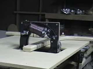
176 Figure 5.23 Crossing over a T shape. 159
 and it was noticed that the fiber line (Figure 5.")


177 Figure 5.24 T shape winding detail. Left after winding the pass in Figure Right after a few circuits. After winding several circuits the material began to build up (Figure 5.26) and it was noticed that the fiber line (Figure Right) was not winding far into the T s intersection. This is because the spools were facing away from the intersection as in Figure 5.26 Left and Figure Right. This orientation was changed (to Figure 5.26 Right) so the fiber line could wind up on the intersection. Figure 5.25 The fiber line Left - can be seen coming from the left side, from the spools. Right with the fiber line on the wrong side, the fiber can t get to the intersection. This CAD model accurately represents the sizes of the T and the machine. 160


178 Figure 5.26 The fiber line II. Left the spools, and hence the fiber placement (there is no special eyelet for this machine) are seen not facing the T s intersection. Right the spools are facing the T s intersection. In Figure 5.27 the intersection of the T is shown before and after fiber is wound up the intersection. This solution was introduced in Figure Figure 5.27 Winding up the intersection. 161


179 Figure 5.28 Winding up the other legs. Left it seem there was enough stiction in the prepreg to wind up each leg quite far. Right the overlapping of the hoop windings. After the T was wound sufficiently with composite it was wound in the same method with heat-shrink tape (Figure 5.29) from Durastone ( It was then cured in an autoclave at BYU s composites lab. The heat shrink-tape is used to compact the outside surface of the fibers and force the fibers snuggly against the mandrel. Figure 5.29 Heat shrink tape After the heat-shrink tape was removed it was noticed that the T s surface had the same effect the O shape did in Figure It has a sort of valley down the center. In 162
. Under this area down the center is where the valleys occur.")

180 Figure 5.30 the shrink-tape, after curing, was left on and photographed. In the center of the mandrel, there is a lighter color due to air under the tape (this is difficult to see even in the original photo). Under this area down the center is where the valleys occur. Like with all the Lotus shapes, this is an effect of a) tension that was too slack, and 2) the flat sections of the mandrel (not having more positive curvature). Figure 5.30 Valleys. Left the light section down the middle of this picture, Right correlates with the valleys in this picture. The T shape was wound with a hybrid setup. On one spool was prepreg carbon fiber and the other had prepreg fiberglass. The Figure 5.30 Right shows an area where fiberglass was wound on the left and carbon fiber was wound to the right. During the rest of the winding the fibers were totally integrated. Overall the T (Figure 5.32) was covered well, considering the narrow tows and few circuits. Figure 5.31 details the valleys at the intersection. 163


181 Figure 5.31 Detail of the intersection. Left a small valley can be seen on the vertical face of the T. This valley is much smaller than those on the top. The finish on the side is fairly good otherwise. Right notice a gap in the center of the intersection. This may have been caused by the operator trying to cover just one side (the other side). Figure 5.32 The T, covered. 164

.")

182 Figure 5.33 The finished T U For analysis, the U shape was first wound with colored ribbon (Figure 5.34 left). The Lotus machine continuously wound the ribbon so that it didn t need to be cut. The ribbon was wound with helical and hoop windings as seen in Figure 5.34 (right). The mandrel in Figure 5.34 has a cross-section that has a hard corner. Composite fibers would probably break if wound around this corner. Figure 5.34 U shape with colored ribbon. 165


.")
183 A new mandrel was made for the U for this research paper as in Figure This mandrel was also wound with colored ribbon as a practice run. The colored ribbon shows the angles much better than the carbon fiber (black on black). Figure 5.35 U shape with colored ribbon II. The ribbon was removed and the U shape was wound with carbon fiber, as seen in Figure 5.36 (left). Next it was wound with heat-shrink tape as seen in Figure 5.36 (right). Figure 5.36 The U shape. Left winding. Right with heat-shrink tape. 166


 on the vertical face of the leg, the surface is")
184 The U shape was made large enough so the mandrel could always stay in the center of the work envelope. There were no problems winding the U shape. In Figure 5.37 many angles of fiber can be seen before and after curing. Notice that in Figure 5.37 (right) on the vertical face of the leg, the surface is relatively free of defects. Figure 5.37 Before and after curing, respectively. Figure 5.38 The finished U. 167


185 5.3.5 S The S shape is unique in that it has to fit around the outside edges of the Lotus machine. In Figure 5.39, we see that to either side of the machine is a leg of the S shape. This mandrel has plenty of room, so that it can remain in the center of the work envelope through the entire winding process. Figure 5.39 Winding the center of the S. The S shape was first wound with colored tape with helical and hoop winding angles as seen in Figure Figure 5.40 Helical and hoop windings, respectively. 168


186 Figure 5.41 Progression of the S shape through the machine. Figure 5.42 Before and after. Left the longest angles here appear tangent to the inner radius as predicted. Right the S was mainly covered with hoop windings. 169
 and was cured with the rest of the Lotus shapes.")


187 The S was then wound with shrink-tape (Figure 5.43) and was cured with the rest of the Lotus shapes. The S shape after curing has the same pattern on the horizontal surface down its center as can be seen in Figure 5.44 (if the picture quality is good enough). The S had the same valleys down its center as the rest of the shapes. Figure 5.43 Before and after the autoclave Figure 5.44 S detail. The valleys can be seen down the center of the top surface. 170


188 Figure 5.45 The finished S SMALL LOTUS SHAPES Some small Lotus shapes were wound by a somewhat different method. The small parts were held by hand (instead of resting on the table), and were wound entirely within the work envelope. The O shape has no smaller Lotus shape because if the Lotus machine can intersect an O shape, then it is too large to be called a small Lotus shape. The small Lotus shapes are shown in Figure Figure 5.46 The small Lotus shapes before and after being wound. The mandrels are 3/8 ths inch copper tubing. 171


189 Figure 5.47 Detail of making small Lotus shapes. Left notice the operator s hands hold the small mandrel from both sides of the machine. Right detail of winding a 3D Lotus T shape. The small shapes were wound with fair success. The L shape was easiest and ended up having the best surface finish. This is partly because the operator was making a determined effort to wind it with an even pattern, and partly due to the L shape being the only shape to get wound with heat-shrink tape. The U shape was the one that turned out worst. The small U shape doesn t allow the fiber down into the U and to its sides easily. 172


190 Figure 5.48 Detail of the small Lotus shapes After going through the autoclave. 5.4 ISSUES In winding the Lotus shapes there were some issues that are worth mentioning. First, the Lotus machine, as made for this thesis, is not perfect. There is an issue with the shuttle and race. As the separation line between the shuttle halves passes the driving gear, it becomes a gap as seen in Figure This gap grows large, like in this image, if there is a lot of friction in the system. Usually this gap causes no problems. Each time the separation line passes the driving gear this gapping makes some noise. While the noise is not a real problem, the fact that the machine makes a lot of noise is because it is just a prototype and not made to tight tolerances. One reason for the gapping could be that there is nothing holding the shuttle halves to each other, they are 173
 If the friction in the shuttle, race, and driver system was reduced then the remaining tension in the system would be from the tension from the spools as they lay the fiber.")
191 just set in the race, and one pushes the other. (If the shuttles had a way to connect they would have to disconnect for the machine to open.) If the friction in the shuttle, race, and driver system was reduced then the remaining tension in the system would be from the tension from the spools as they lay the fiber. The tension added by the spools is probably the main reason the 4 spool setup that wound the O shape was having so much trouble. At low speed this gapping can be a problem because there is not enough momentum to push the following shuttle through. This problem was solved by relentlessly finding friction areas and smoothing them out. Figure 5.49 The gap. The round circle is a bearing that holds the end of the drive shaft. Next is a related issue. The outside edge of the shuttle is a gear. The gear sits in the race which is made of ABS plastic. One reason plastic was used was so that the gear could eventually grind its own groove if it didn t fit well immediately. At issue is the result of this reasoning. The plastic does get ground down by the gear, but where does the plastic debris go? It probably ends up on the mandrel, in Figure 5.50, ABS debris is sitting where it fell, towards the back of the machine. In a system made for production the design should prevent things from falling onto the work-piece. 174

192 Also, if other special tools are used with the Lotus machine, they may cause debris to drip or fly and each of those systems should have a way to contain the debris they cause and keep it from damaging, the operator, the machine, and the work-piece. Figure 5.50 ABS debris. Next, is the spool of fiber. In Figure 5.51 we see spool of fiber that is fraying. This happened a number of times while making the parts. When this fraying happened, the friction in the system increased dramatically and a few times the fibers broke. The main reason this is happening is probably because of the rudimentary method used to respool the material as seen in Figure 5.9. If the fiber was re-spooled with more care, then perhaps this fraying wouldn t have happened. Another reason may be because this fiber had do not use written on it, because it was a free sample of fiber that didn t meet the specs necessary to be released. Last, prepreg is supposed to be kept cold until it is placed. The prepreg used here sat at room temperature for a couple of days while these parts were being made. As the temperature increased the tackiness of the prepreg increased causing it to not unwind. 175


193 Figure 5.51 Fraying fiber. Next is an issue to do with calculating angles and pitch, etc. In Figure 5.52 we see that the ribbon being place is draping to the side before it winds on the mandrel. In the image to the left the mandrel is moving towards the right and in the image to the right it is moving to the left. This drape angle was not calculated for this research, but accounting for it is necessary to make reliable windings. (Filament winding software have this built in with their calculations.) Figure 5.52 Winding drape angle. 176

194 5.5 WRAPPING ON SHRINK TAPE The Lotus machine can process unique shapes. Because of this, other processes may have a difficult time working with parts processed with a Lotus machine. One additional process the Lotus machine did to make the Lotus shapes was to wind heat shrink-tape on to the fiber. This was very helpful and it was easy to modify the system to do it as seen in Figure This heat-shrink tape is another special tool, so the system can be modified to take advantage of the new constraints. In Figure 5.54 the shrink-tape is attached directly to the shuttle, giving the machine a smaller profile which decreases the limits on the dimensions of the Lotus shapes. Figure 5.53 Heat-shrink tape setup on the same spool holding system used for the fiber spools. 177


195 Figure 5.54 Without the spool holders the Lotus machine s working profile is smaller, giving the system more flexibility. 5.6 IDEAL COMPOSITES MANUFACTURING PROCESS It was stated in Chapter 4 that, when automated, the Lotus process can be like an ideal composites manufacturing process because it can be: fast, reliable, inexpensive, and safe. In its current form as a partially automated machine it can be fast, inexpensive, and sort of safe, but definitely not yet reliable FAST Section analyzes the speed of the process RELIABLE The reliability of the process cannot be achieved by the partially automated Lotus filament winding machine made for this thesis. A higher degree of automation is necessary to ensure better quality. Some of the qualities or characteristics of a good part, that the Lotus machine did do is wind the Lotus shapes with continuous, uncut, and aligned (oriented, not really aligned) fibers. 178
196 The fibers were placed continuously from the spools. This satisfies the requirement of being continuous. At most, the spools were changed out (or the fibers broke) three times for any of the shapes. Some of the shapes were wound to a thinner surface thickness than others and were able to cover the entire mandrel with uncut fibers. This partially satisfies the requirement that the fibers be placed uncut. The shapes that had 2 and 3 changeovers can be called continuously wound with 2 or 3 tows. Many circuits were laid from each spool before any of them had to be changed out. This shows that the fibers were not only continuous, but of circuit length. The fibers would have been uncut if, 1) the spools carried the entire skein necessary to wind all the layers, and 2) if the fibers had not broken. Were the fibers aligned? The fibers were not aligned in the truest sense of the word. They were not placed according to any specification. At times the mandrel was pushed through faster resulting in longer, helical windings. Both helical and polar windings were wound. But the fibers were not aligned reliably enough to entirely cover the surface of the Lotus shaped mandrels with one layer. It should be remembered that the tow was inches wide, and it is difficult to get that to sit right next to or lap over the previous winding, because the pitch (p) would have to be approximately in inch increments per rotation. This is inches per second, because the machine spins at 60 RPMs. The outside arclength pitch (P) would also have to be inches, so the angular pitch (φ) would have to have been 0.81 degrees. The system was not tightly controlled enough to wind that closely. If the winding of the wider heat-shrink tape (one inch wide) was considered, then the machine can wind material so that it is aligned, or at 179
197 least so the entire mandrel can be covered with each circuit. If a wider tow were used it would have been easier to align the fibers. Sometimes fiber alignment is called orientation of the fibers. The fibers were oriented circumferentially and helically for winding the Lotus shapes. The Lotus machine made for this research is inexpensive, but it is not reliable because the controls are limited. A Lotus machine should be simple to automate, but it will increase the price of the machine considerably. Compared to the value of composite parts, the high cost of labor, and the improvement in quality the Lotus filament winding machine has to offer, it may be seen as an inexpensive machine INEXPENSIVE The Lotus machine made for this research is inexpensive, more as a result of resourcefulness than on any particular merits of the system. A better designed automated system will cost plenty. Even if the Lotus filament winding was fully automated and the machinery cost was considerable, would the setup be inexpensive? Yes. It would save on labor costs. It would make reliable parts. It would be fast. It would make parts of higher quality than other processes. It would be flexible enough that it could wind on various mandrels. It processes expensive raw materials (prepreg tow can cost up to $100/lb). Compared to the price of an expensive Lotus machine, all the costs that it will save will make it an inexpensive machine. The partially automated Lotus machine can also be redesigned to have a higher degree of automation with gears and jigs, depending on the complexity of the mandrels. 180
198 This would result in a less expensive machine that is less flexible, but may be totally adequate for making parts of certain sizes and shapes SAFE Is the Lotus filament winding process safe to the operator, work-piece, and the Lotus machine? The operator wore latex gloves, safety goggles, and a dust mask during the winding process for the Lotus shapes. The operator had no trouble with splinters or breathing. At times the goggles would fill with perspiration. The operator doesn t like to wear all that safety equipment. He likes to remain safe, but one reason he is developing this process is to make an automated system for winding complex shapes, so that operators will not have to wear this kind of uncomfortable equipment all day. The operator got a blister from tightening the motor (cordless drill) to the drive gear. This blister came off and started bleeding while winding the T and a piece of tape was used to cover it up and continue working (see Figure 5.54). Since the motor is part of the Lotus filament winding process, a different motor setup is recommended. One that doesn t require the operator s grip force to exceed the torque of a securely tightened drill. Also, the batteries of the drill were always running out, so a cordless motor is not recommended. One good feature of the drill was that it had a lot of torque settings to keep the machine and mandrels safe if there was too much friction in the system. With one mandrel, which was not one of the Lotus shapes wound for this thesis, the machine did hit the mandrel. The mandrel was a large coil shaped copper tube. Figure 5.55 shows the setup. In this figure the machine was spinning CCW. One of the spools hit the copper tube, which bent and was pulled down into the slot in the table. At 181

199 this point the machine stopped spinning and the drill was ratcheting like mad. The moment it happened, the operator backed up quickly and turned off the drill. The malleable copper tube was mangled and one of the spool centers had a small chip broken off it, but nothing else was damaged. Obviously, when working with moving parts there is some potential for accidents. There are a number of reasons this one happened. First, the operator was being a bit careless by trying to wind a complex shape without making sure the part would fit in the machine with a safety gap between the mandrel and the moving parts on the shuttle. Next, the mandrel, which is rather complex, is constantly being tugged at by the machine as the fibers are wound in tension, (it s malleable and may have deformed), and the operator has to watch the close side, the middle and the far side of the machine all at once to make sure the machine wouldn t hit the mandrel. Then after winding a few circuits with success the operator began to relax. That was it mostly, operator inattention. Figure 5.55 Winding a 3D S shape somewhat carelessly. 182
Kolfiberarmering för avancerade tillämpningar
 Kolfiberarmering för avancerade tillämpningar 2012-10-10 About Oxeon Business Idea Oxeon develop produce and sell optimized spread tow reinforcement solutions, TeXtreme, to customers with a need for ultra
Experimental Evaluation of Metal Composite Multi Bolt Radial Joint on Laminate Level, under uni Axial Tensile Loading
 RESEARCH ARTICLE OPEN ACCESS Experimental Evaluation of Metal Composite Multi Bolt Radial Joint on Laminate Level, under uni Axial Tensile Loading C Sharada Prabhakar *, P Rameshbabu** *Scientist, Advanced
Composite 3D Printing: A High Strength Solution for Anything from Prototypes to Fixtures
 Composite 3D Printing: A High Strength Solution for Anything from Prototypes to Fixtures A few months prior, Walters had been faced Arow Global is a small, innovative around the corners, that stiffens
CONTINUOUS-LENGTH SPREAD TOW +α /-β FABRICS
 1/7 CONTINUOUS-LENGTH SPREAD TOW +α /-β FABRICS Fredrik Ohlsson, Product Manager - Materials Dr. Nandan Khokar, R&D Manager Oxeon AB, Borås, Sweden ABSTRACT Fabrics with +α/-β orientation of spread tows
Geometric Dimensioning and Tolerancing
 Geometric Dimensioning and Tolerancing (Known as GDT) What is GDT Helps ensure interchangeability of parts. Use is dictated by function and relationship of the part feature. It does not take the place
NOVEL CONCEPT OF THREE-DIMENSIONAL (3D) THICK COMPOSITE STRUCTURE FROM PITCH BASED CARBON FIBRE FOR MACHINE TOOL APPLICATIONS
 THICK COMPOSITE STRUCTURE FROM PITCH BASED CARBON FIBRE FOR MACHINE TOOL APPLICATIONS") NOVEL CONCEPT OF THREE-DIMENSIONAL (3D) THICK COMPOSITE STRUCTURE FROM PITCH BASED CARBON FIBRE FOR MACHINE TOOL APPLICATIONS O.Uher 1, J. Smolik 2, M. Ruzicka 3 1 CompoTech Plus s.r.o., Druzstevni 159,
NOVEL CONCEPT OF THREE-DIMENSIONAL (3D) THICK COMPOSITE STRUCTURE FROM PITCH BASED CARBON FIBRE FOR MACHINE TOOL APPLICATIONS O.Uher 1, J. Smolik 2, M. Ruzicka 3 1 CompoTech Plus s.r.o., Druzstevni 159,
DEVELOPMENT OF A NOVEL TOOL FOR SHEET METAL SPINNING OPERATION
 DEVELOPMENT OF A NOVEL TOOL FOR SHEET METAL SPINNING OPERATION Amit Patidar 1, B.A. Modi 2 Mechanical Engineering Department, Institute of Technology, Nirma University, Ahmedabad, India Abstract-- The
Geometric Tolerances & Dimensioning
 Geometric Tolerances & Dimensioning MANUFACTURING PROCESSES - 2, IE-352 Ahmed M. El-Sherbeeny, PhD KING SAUD UNIVERSITY Spring - 2015 1 Content Overview Form tolerances Orientation tolerances Location
AMTS STANDARD WORKSHOP PRACTICE. Bond Design
 AMTS STANDARD WORKSHOP PRACTICE Reference Number: AMTS_SWP_0027_2008 Date: December 2008 Version: A 1 Contents 1 Technical Terms...3 2 Scope...3 3 Primary References...3 4 Basic...3 4.1 Typical joint types...4
Three-dimensional fabric material
 United States Patent: 4,001,478 1/20/03 4:34 PM ( 101 of 105 ) United States Patent 4,001,478 King January 4, 1977 Three-dimensional fabric material Abstract Three-dimensional impregnated filamentary materials
FORM Q-120 PROCEDURE SPECIFICATION FOR CLASS II VESSELS (Revision C 2017) Part I Fabrication
 Part I Fabrication") FORM Q-120 Part I Fabrication PROCEDURE SPECIFICATION NUMBER: NOTE: Procedure Specification Form Q-120 for Class II vessels consists of three parts. Part I, Fabrication, shall be completed for each separately
FORM Q-120 Part I Fabrication PROCEDURE SPECIFICATION NUMBER: NOTE: Procedure Specification Form Q-120 for Class II vessels consists of three parts. Part I, Fabrication, shall be completed for each separately
CH # 8. Two rectangular metal pieces, the aim is to join them
 CH # 8 Screws, Fasteners, and the Design of Non-permanent Joints Department of Mechanical Engineering King Saud University Two rectangular metal pieces, the aim is to join them How this can be done? Function
Material optimization of composite drive shaft assembly in comparison with conventional steel drive shaft
 Material optimization of composite drive shaft assembly in comparison with conventional steel drive shaft Mr. V.l.Narayana 1 Associate Professor,Department Of Mechanical Engineering,St.Ann s College Of
Contents. Notes on the use of this publication
 Contents Preface xxiii Scope Notes on the use of this publication xxv xxvi 1 Layout of drawings 1 1.1 General 1 1.2 Drawing sheets 1 1.3 Title block 2 1.4 Borders and frames 2 1.5 Drawing formats 2 1.6
Technical Guide for Glass Cutting Section 1 - Two Basic Types of Cutting
 Section 1 - Two Basic Types of Cutting Part 2 Pressure Cutting Basic Principles of Pressure Cutting This portion of Part 2 deals with those aspects of the basic principles of glass cutting that are common
Meeting the volumes, cost and technical challenges for further penetration of composites in airframes
 Meeting the volumes, cost and technical challenges for further penetration of composites in airframes Prof. Prasad Potluri EPSRC High Value Manufacturing Catapult Fellow Professor of Robotics and Textile
Drawing. Fig. 1 Drawing
 Drawing Drawing is a metalworking process which uses tensile forces to stretch metal. It is broken up into two types: sheet metal drawing and wire, bar, and tube drawing. The specific definition for sheet
The Stub Loaded Helix: A Reduced Size Helical Antenna
 The Stub Loaded Helix: A Reduced Size Helical Antenna R. Michael Barts Dissertation submitted to the Faculty of the Virginia Polytechnic Institute and State University in partial fulfillment of the requirements
An Analysis of EM Railgun Cross Section Designs. Joshua B. Root Vince Olmstead Dr. Andrew G Littlefield Dr. Krystyna Truszkowska
 An Analysis of EM Railgun Cross Section Designs Joshua B. Root Vince Olmstead Dr. Andrew G Littlefield Dr. Krystyna Truszkowska Introduction Electromagnetic (EM) railguns are of interest to the military
ROOP LAL Unit-6 Lathe (Turning) Mechanical Engineering Department
 Mechanical Engineering Department") Notes: Lathe (Turning) Basic Mechanical Engineering (Part B) 1 Introduction: In previous Lecture 2, we have seen that with the help of forging and casting processes, we can manufacture machine parts of
Notes: Lathe (Turning) Basic Mechanical Engineering (Part B) 1 Introduction: In previous Lecture 2, we have seen that with the help of forging and casting processes, we can manufacture machine parts of
Tool School - Rotary Draw Bending Tooling. An Engineer s Guide to Bending Tubes
 Tool School - Rotary Draw Bending Tooling An Engineer s Guide to Bending Tubes Tube Form Solutions Tool School Rotary Draw Bending Tooling Tool School Agenda: Introduction To Rotary Draw Bending Engineering
A Detailed Examination of Waveforms from Multiple Sensors on a Composite Pressure Vessel (COPV)
") A Detailed Examination of Waveforms from Multiple Sensors on a Composite Pressure Vessel (COPV) By M. A. Hamstad University of Denver, Department of Mechanical and Materials Engineering Denver, CO USA
A Detailed Examination of Waveforms from Multiple Sensors on a Composite Pressure Vessel (COPV) By M. A. Hamstad University of Denver, Department of Mechanical and Materials Engineering Denver, CO USA
Unit IV Drawing of rods, wires and tubes
 Introduction Unit IV Drawing of rods, wires and tubes Drawing is a process in which the material is pulled through a die by means of a tensile force. Usually the constant cross section is circular (bar,
0.20. Record Page 1 of 19
 Page 1 of 19 Page 2 of 19 Page 3 of 19 Page 4 of 19 Page 5 of 19 ASME BPVC.III.1.ND-2015 Page 6 of 19 ð15þ Figure ND-3325-1 Some Acceptable Types of Unstayed Flat Heads and Covers GENERAL NOTE: The illustrations
ENVELOPE REQUIREMENT VERSUS PRINCIPLE OF INDEPENDENCY
 ENVELOPE REQUIREMENT VERSUS PRINCIPLE OF INDEPENDENCY Carmen SIMION, Ioan BONDREA University "Lucian Blaga" of Sibiu, Faculty of Engineering Hermann Oberth, e-mail:carmen.simion@ulbsibiu.ro, ioan.bondrea@ulbsibiu.ro
Core Competencies: The base for quality winding
 Core Competencies: The base for quality winding 2005 AIMCAL Fall Technical Conference October 16 19, 2005 Myrtle Beach, SC Web Coating - Laminating Section Paul Roth VP / Director Sales Appleton Mfg. Div,
Precision Folding Technology
 Precision Folding Technology Industrial Origami, Inc. Summary Nearly every manufacturing process has experienced dramatic improvements in accuracy and productivity as well as declining cost over the last
FABRICS & BAGGING Fiberglass Cloth. Kevlar Cloth. Carbon Fiber Cloth. Mia Vacuum Bagging Supplies
 FABRICS & BAGGING This comprehensive selection of materials from the biggest names in the industry offers solutions for the construction of large, lightweight molds and production parts. 62-63 Fiberglass
Injection moulding. Introduction. Typical characteristics of injection moulded parts
 Injection moulding Introduction Injection molding is generally used to produce thermoplastic polymers. It consists of heating of thermo plastic materials until it melts and then injecting into the steel
Technical Report Synopsis: Chapter 4: Mounting Individual Lenses Opto-Mechanical System Design Paul R. Yoder, Jr.
 Technical Report Synopsis: Chapter 4: Mounting Individual Lenses Opto-Mechanical System Design Paul R. Yoder, Jr. Introduction Chapter 4 of Opto-Mechanical Systems Design by Paul R. Yoder, Jr. is an introduction
WORK SURFACE I highly recommend getting an Olfa knife. It is difficult to cut 1/2 foamcore with just an Exacto. RAZOR KNIFE CUTTING MAT WIRE CUTTERS
 RAZOR KNIFE CUTTING MAT WIRE CUTTERS MARKING TOOLS PLIERS CIRCLE STENCIL SMALL WOOD SAW COMPASS 12 METAL RULER* > 16 RULER HOT GLUE GUN RIGHT TRIANGLE SCREWDRIVER Find a sturdy table that is in a well-lit
Stub Height Uses: Number to use for bender take-up.
 Conduit Bending Basics: Conduit Bender Guide The line of Klein Tools conduit benders have been designed for performance and durability exceeding the expectations of today s professional. It is recommended
EFFECTS OF STITCH PATTERN ON THE MECHANICAL PROPERTIES OF NON-CRIMP FABRIC COMPOSITES
 EFFECTS OF STITCH PATTERN ON THE MECHANICAL PROPERTIES OF NON-CRIMP FABRIC COMPOSITES Leif E. Asp, Fredrik Edgren and Anders Sjögren SICOMP AB, P O Box 14, SE-431 22 Mölndal, Sweden ABSTRACT Mechanical
Module-4 Lecture-2 Perpendicularity measurement. (Refer Slide Time: 00:13)
") Metrology Prof. Dr. Kanakuppi Sadashivappa Department of Industrial and Production Engineering Bapuji Institute of Engineering and Technology-Davangere Module-4 Lecture-2 Perpendicularity measurement (Refer
Metrology Prof. Dr. Kanakuppi Sadashivappa Department of Industrial and Production Engineering Bapuji Institute of Engineering and Technology-Davangere Module-4 Lecture-2 Perpendicularity measurement (Refer
DRAFTING MANUAL. Dimensioning and Tolerancing Rules
 Page 1 1.0 General This section is in accordance with ASME Y14.5-2009 Dimensioning and Tolerancing. Note that Rule #1 is the only rule that is numbered in the 2009 standard. All of the other rules fall
Rotary sizing of tube and pipe on the mill
 Rotary sizing of tube and pipe on the mill By Bruce Chidlow, Kusakabe Electric & Machinery Co Ltd, Kobe, Japan Introduction The sizing methods used on tube and pipe mills have not changed significantly
ParkJet Builder s Manual
 ParkJet Builder s Manual Thank you for purchasing the ParkJet. The ParkJet is a profile ducted fan airplane that can be flown in a larger park. The ParkJet was initially designed by Scott Stoops and modified
Clips, an Alternative Fastener System
 395 Clips, an Alternative Fastener System by Thomas Doppke There are times when a screw or threaded product just won t fit the attachment requirements. Not enough space, backside clearance, not reachable
Factors to Consider in Plastic Molded Design
 9 Factors to Consider in Plastic Molded Design Table Of Contents Introduction 3 Design 4 1. Draft... 4 2. Surface Finish... 5 3. Witness Lines... 6 4. Wall Thickness... 6 5. Support/Straight Ribs Thickness...
Think like a machinist when creating solid models
 Think like a machinist when creating solid models Article by Milton Florest President Tooling Research Inc. 81 Diamond St. Walpole, MA 02081 Website www.tooling research.com 508 668 1950 Since the introduction
Comparison of the Mechanical Properties Between 2D and 3D Orthogonal Woven Ramie Fiber Reinforced Polypropylene Composites
 Comparison of the Mechanical Properties Between 2D and 3D Orthogonal Woven Ramie Fiber Reinforced Polypropylene Composites Comparison of the Mechanical Properties Between 2D and 3D Orthogonal Woven Ramie
AUTOMATED MACHINE TOOLS & CUTTING TOOLS
 CAD/CAM COURSE TOPIC OF DISCUSSION AUTOMATED MACHINE TOOLS & CUTTING TOOLS 1 CNC systems are used in a number of manufacturing processes including machining, forming, and fabrication Forming & fabrication
Pneumatic Catapult Games Using What You Know to Make the Throw. Pressure x Volume = Energy. = g
 Pneumatic Catapult Games Using What You Know to Make the Throw Pressure x Volume = Energy θ Mega Pascal s KE PE Range = Release Velocity g 2 1 Pneumatic Catapult Games Using What You Know to Make the Throw
SECTION EXPANSION FITTINGS AND LOOPS FOR HVAC PIPING
 SECTION 230516 - EXPANSION FITTINGS AND LOOPS FOR HVAC PIPING PART 1 - GENERAL 1.1 RELATED DOCUMENTS A. Drawings and general provisions of the Contract, including General and Supplementary Conditions and
Investment Casting Design Parameters Guide for Buyer
 Investment Casting Design Parameters Guide for Buyer The following guidelines and technical information outline what an investment casting is capable of offering. It will cover dimensional and structural
TENSILKUT ENGINEERING
 TENSILKUT ENGINEERING For Accurate Test Specimens Manufacturer of equipment for the accurate preparation of physical test specimens since 1955 SIEBURG INTERNATIONAL, INC. 1901 Clydesdale Street, Maryville,
How to build a Javelin Skiff
 How to build a Javelin Skiff This is not your grandfather s plywood boat! The Javelin involves a high-tech type construction, called composite. The hull can be constructed with foam or plywood; these materials
WORKING of nidaplast
 nida 8/gb - 03.07.07 Technical Information. 2 WORKING of nidaplast nidaplast is a polypropylene honeycomb covered on both faces with a soft polyester nonwoven fabric. It is available in 2500 x 1200 mm
Sample Questions for the Engineering Module
 Sample Questions for the Engineering Module Subtest Formalising Technical Interrelationships In the subtest "Formalising Technical Interrelationships," you are to transfer technical or scientific facts
The Canadian Tire Paint Roller A Technical Description
 A Technical Description Eric Morlang Table of Contents 1. General Description of the Paint Roller... 3 2. Part-By-Part Description of the Paint Roller... 4 2.1 Body... 4 2.1.1 Handle... 4 2.1.2 Wire...
Development of a fabric winding system for the automated manufacture of prefabricated wind turbine blade roots
 Graduate Theses and Dissertations Graduate College 2011 Development of a fabric winding system for the automated manufacture of prefabricated wind turbine blade roots Benjamin Amborn Wollner Iowa State
Mechanical Vice Grips. Mechanical Wedge Action Grips
 Mechanical Vice Grips 734B 750 N (150 lbf) 768C 10 kn (2000lbf) Thwing-Albert s Mechanical Vice Grips are designed for measuring materials up to 10 kn. They are ideal for general tensile strength testing
Why gundrills? Dr. Viktor P. Astakhov, Independent Consultant
 Why gundrills? Dr. Viktor P. Astakhov, Independent Consultant Gundrilling, one of the basic and frequently performed material removal processes in the automotive, die and mold, and turbine industries,
Forces on a 2D Plane
 C h a p t e r 3 Forces on a 2D Plane In this chapter, you will learn the following to World Class standards: 1. Measuring the Magnitude and Direction of a Force Vector 2. Computing the Resultant Force
Wire Drawing 7.1 Introduction: stock size
 Wire Drawing 7.1 Introduction: In drawing, the cross section of a long rod or wire is reduced or changed by pulling (hence the term drawing) it through a die called a draw die (Fig. 7.1). Thus, the difference
DESIGN OF MACHINE MEMBERS-I
 Code No: R31035 R10 Set No: 1 JNT University Kakinada III B.Tech. I Semester Regular/Supplementary Examinations, Dec - 2014/Jan -2015 DESIGN OF MACHINE MEMBERS-I (Mechanical Engineering) Time: 3 Hours
Copyrighted Material. Copyrighted Material. Copyrighted. Copyrighted. Material
 Engineering Graphics ORTHOGRAPHIC PROJECTION People who work with drawings develop the ability to look at lines on paper or on a computer screen and "see" the shapes of the objects the lines represent.
Page 1 of 5 Application Engineering Note Proc. 001 Interlock Armor and Corrugated Steel Tape Cables Pulling Grip Installation Procedure Rev.
 Page 1 of 5 Scope: The scope of this procedure is to describe how to properly install a cable pulling grip on an Optical Cable Corporation interlocked armor (ILA) and corrugated steel tape (CST) fiber
Near Net Shape Preforming by 3D Weaving Process
 Near Net Shape Preforming by 3D Weaving Process A thesis submitted to The University of Manchester for the degree of Doctor of Philosophy In the Faculty of Engineering and Physical Sciences. 2012 Dhavalsinh
REVISION LIST CHAPTER 25: AFT WINDOWS. The following list of revisions will allow you to update the Legacy construction manual chapter listed above.
 REVISION LIST CHAPTER 25: The following list of revisions will allow you to update the Legacy construction manual chapter listed above. Under the Action column, R&R directs you to remove and replace the
COIL WINDING ISSUES P. Fabbricatore INFN Genova LCD - Magnet 13Oct09. Coil winding issues
 Coil winding issues Based on experience acquired with CMS coil construction, some preliminary considerations about the envisaged winding (and in general manufacturing) issues of a large superconducting
Straight Bevel Gears on Phoenix Machines Using Coniflex Tools
 Straight Bevel Gears on Phoenix Machines Using Coniflex Tools Dr. Hermann J. Stadtfeld Vice President Bevel Gear Technology January 2007 The Gleason Works 1000 University Avenue P.O. Box 22970 Rochester,
CES EduPack Case Studies: Process Selection
 CES EduPack Case Studies: Process Selection Professor Mike Ashby Department of Engineering University of Cambridge M. F. Ashby, 2016 For reproduction guidance, see back page This case study document is
CDI Revision Notes Term 1 ( ) Grade 11 General Unit 1 Materials and Unit 2 Fundamentals of Electronics
 Grade 11 General Unit 1 Materials and Unit 2 Fundamentals of Electronics") CDI Revision Notes Term 1 (2017 2018) Grade 11 General Unit 1 Materials and Unit 2 Fundamentals of Electronics STUDENT INSTRUCTIONS Student must attempt all questions. For this examination, you must have:
CDI Revision Notes Term 1 (2017 2018) Grade 11 General Unit 1 Materials and Unit 2 Fundamentals of Electronics STUDENT INSTRUCTIONS Student must attempt all questions. For this examination, you must have:
Essex County College - West Essex Campus Addition And Renovations dlb # / SECTION EXPANSION FITTINGS AND LOOPS FOR HVAC PIPING
 SECTION 230516 - EXPANSION FITTINGS AND LOOPS FOR HVAC PIPING PART I - GENERAL 1.1 RELATED DOCUMENTS A. Drawings and general provisions of the Contract, including General and Supplementary Conditions and
In 1950, plastic film was relatively
 TECHNICAL REPORT BY REINHOLD SCHABLE, APPLICATIONS TECHNOLOGY MANAGER, TIDLAND CORP. Slitting Technology for Film Substrates In 1950, plastic film was relatively uncommon, today it is everywhere. Back
Tools: Scissors, hand held single-hole punch, metal ruler or other good straight-edge, sharp knife or Exacto-knife.
 Instructions for Building a Kepler Paper Model Version 30 Mar 3, 2010 You need the following files: File Sheet # Printer Paper Color Kepler_model_instructionspdf plain b/w Photometerpdf 1 Photo stock color
Developing the Model
 Team # 9866 Page 1 of 10 Radio Riot Introduction In this paper we present our solution to the 2011 MCM problem B. The problem pertains to finding the minimum number of very high frequency (VHF) radio repeaters
Technical Tips. Using Bundle Breaker (rotary corrugated applications) In General, bundle breaker rule is determined based on the following criteria:
 In General, bundle breaker rule is determined based on the following criteria:") Technical Tips 080215_BBarticle Using Bundle Breaker (rotary corrugated applications) Bundle Breaker: a mechanical device designed specifically to separate ganged, multiout sheets after they have been
Technical Tips 080215_BBarticle Using Bundle Breaker (rotary corrugated applications) Bundle Breaker: a mechanical device designed specifically to separate ganged, multiout sheets after they have been
Module 10 : Improvement of rock mass responses. Content
 IMPROVEMENT OF ROCK MASS RESPONSES Content 10.1 INTRODUCTION 10.2 ROCK REINFORCEMENT Rock bolts, dowels and anchors 10.3 ROCK BOLTING MECHANICS Suspension theory Beam building theory Keying theory 10.4
NOTICE. The above identified patent application is available for licensing. Requests for information should be addressed to:
 Serial No.. Filing Date 1 July 1 Inventor Earl S. Nickerson Wayne C. Tucker NOTICE The above identified patent application is available for licensing. Requests for information should be addressed to: ÄBprovsa
1/2/2016. Lecture Slides. Screws, Fasteners, and the Design of Nonpermanent Joints. Reasons for Non-permanent Fasteners
 Lecture Slides Screws, Fasteners, and the Design of Nonpermanent Joints Reasons for Non-permanent Fasteners Field assembly Disassembly Maintenance Adjustment 1 Introduction There are two distinct uses
School of Materials Science and Engineering, Beihang University, Beijing , China.
 EFFECT OF SIZING AGENT ON THE INTERFACIAL ADHESION OF CARBON FIBER-REINFORCED POLYAMIDE 6 COMPOSITES Tao Zhang 1, Yueqing Zhao 2, Hongfu Li 3, Boming Zhang 4 1 School of Materials Science and Engineering,
AC : STUDYING THE PHYSICAL PROPERTIES AND AUX- ETIC BEHAVIOR OF 3D-PRINTED FASTENERS
 AC 212-492: STUDYING THE PHYSICAL PROPERTIES AND AUX- ETIC BEHAVIOR OF 3D-PRINTED FASTENERS Prof. Larry D. Peel P.E., Texas A&M University, Kingsville Larry Peel received an A.S. from Snow College, in
Metallic Coil-Polymer Braid Composites: II. Material Processing and Characterization
 Metallic Coil-Polymer Braid Composites: II. Material Processing and Characterization Thomas A. Plaisted, Alireza Vakil Amirkhizi, Diego Arbelaez, Syrus C. Nemat-Nasser, and Sia Nemat-Nasser Center of Excellence
B ASIC FISHMOUTH CUTTING
 B ASIC FISHMOUTH CUTTING This tutorial contains videos. Click on the open in a new window. icon and the YouTube footage will This basic tutorial will cover cutting a simple 90 degree fishmouth into round
COMPOSITES LAB MANUAL
 COMPOSITES LAB MANUAL Version 1 Lab 6: Post-cure Processing The original version of this manual was a one student senior design project written by Katherine White, the Composite lab assistant, during Spring
Reversing Gear. Shay Reversing Gear
 Shay Nelson Riedel Nelson@NelsonsLocomotive.com Initial: 9/23/03 Last Revised: 06/05/2004 The reversing gear is another one of those pieces I've been putting off. The reason for the postponement was that
Development of Automated Stitching Technology for Molded Decorative Instrument
 New technologies Development of Automated Stitching Technology for Molded Decorative Instrument Panel Skin Masaharu Nagatsuka* Akira Saito** Abstract Demand for the instrument panel with stitch decoration
Retractable Pool Cover
 Retractable Pool Cover By: Abdulhadi Alkhaldi, Zachary Keller, Cody Maurice, Bradley Miller, and Patrick Weber Team 12 Midpoint Review Document Submitted towards partial fulfillment of the requirements
Experimental and numerical investigation of tube sinking of rectangular tubes from round section
 International Journal of Engineering and Technology sciences (IJETS) ISSN 2289-4152 Academic Research Online Publisher Research Article Experimental and numerical investigation of tube sinking of rectangular
CROWNARC. ARC Integrated Systems
 CROWNARC Screw your new CROWNARC to 2 pieces of 2 x 4 using the 4 holes. Then, mount the 2 x 4 s to the wall. You ll have best control when the CROWNARC is just above waist level. To crown a bow: Lay a
Compression vs. Fusion: The Source of Strength in Fused Sight Glasses for Chemical and Pharmaceutical Processes
 Compression vs. Fusion: The Source of Strength in Fused Sight lasses for Chemical and Pharmaceutical Processes Manufacturers of sight glasses use different combinations of metal and glass to achieve a
SPACER APPLICATION: KEY POİNTS FOR HİGH QUALİTY İG UNİTS
 SPACER APPLICATION: KEY POİNTS FOR HİGH QUALİTY İG UNİTS Application of spacer should be in clean and indoor area. Glass washing machine, hot press machine and spacer application table should be in the
Manufacturing a Composite Wheel Prototype Using 3D Printed Molds
 Minnesota State University, Mankato Cornerstone: A Collection of Scholarly and Creative Works for Minnesota State University, Mankato All Theses, Dissertations, and Other Capstone Projects Theses, Dissertations,
Note: Lay-Up Schedules.
 Fabrication Method This PDE fabrication presentation is designed to display elements of the fabrication processes with accompanying images to better visualize the fabrication process. Please make sure
Preliminary Design of the n2edm Coil System
 Preliminary Design of the n2edm Coil System Christopher Crawford, Philipp Schmidt-Wellenburg 2013-07-03 1 Introduction This report details progress towards the design of an electromagnetic coil package
M. Bücker*, M. Magin. Institute for Composite Materials, Erwin-Schrödinger-Straße 58, Kaiserslautern, Germany
 TESTING OF THE STRENGTH OF AN ALTERNATIVE MANUFACTURING METHOD FOR BOLTED JOINTS USED IN A GFRP-ROTOR OF AN AXIAL-FLUX ELEKTRIC MOTOR FOR SERIAL PRODUCTION IN AUTOMOTIVE M. Bücker*, M. Magin Institute
NMC Charkha: A Design Analysis from Technological Considerations
 NMC Charkha: A Design Analysis from Technological Considerations R.Chattopadhyay, R.B.Chavan and R.K.Nayak Department of Textile Technology Indian Institute of Technology, New Delhi 110 016, India Introduction
White paper. Exploring metal finishing methods for 3D-printed parts
 01 Exploring metal finishing methods for 3D-printed parts 02 Overview Method tested Centrifugal disc Centrifugal barrel Media blasting Almost all metal parts whether forged, stamped, cast, machined or
EVERYTHING TO KNOW ABOUT OVERMOLDED CABLE ASSEMBLIES
 EVERYTHING TO KNOW ABOUT OVERMOLDED CABLE ASSEMBLIES By Brian Morissette, Cable Assembly Product Manager Epec Engineered Technologies Overmolding has dramatically changed the appearance and functionality
An intro to CNC Machining
 An intro to CNC Machining CNC stands for Computer Numeric Control. CNC machining involves using a machine controlled by a computer to machine material. Generally the machine is either a milling machine
1. Enumerate the most commonly used engineering materials and state some important properties and their engineering applications.
 Code No: R05310305 Set No. 1 III B.Tech I Semester Regular Examinations, November 2008 DESIGN OF MACHINE MEMBERS-I ( Common to Mechanical Engineering and Production Engineering) Time: 3 hours Max Marks:
Simple Loop Antennas By TWR Bonaire Engineering
 Improving Medium Wave Reception Simple Loop Antennas By TWR Bonaire Engineering Dave Pedersen dpedersen@twr.org The Problem with listening to distant medium wave radio stations Radio stations on the Medium
Screw. Introduction This Rokenbok STEM-Maker lesson will use the following steps to learn about the screw. Learning Objectives. Resources.
 Screw Progression: Applications in Design & Engineering - Section 6 Curriculum Packet v2.0 Introduction This Rokenbok STEM-Maker lesson will use the following steps to learn about the screw. 1. Learn 2.
Design Guide: CNC Machining VERSION 3.4
 Design Guide: CNC Machining VERSION 3.4 CNC GUIDE V3.4 Table of Contents Overview...3 Tolerances...4 General Tolerances...4 Part Tolerances...5 Size Limitations...6 Milling...6 Lathe...6 Material Selection...7
Rethink Thread Repair. Think Recoil
 Rethink Thread Repair. Think Recoil Watch the demo Proudly Distributed by: Recoil Bringing versatility to a range of applications Recoil threaded inserts, installation tooling, taps, gauges, and thread-repair
AC : CLARIFICATIONS OF RULE 2 IN TEACHING GEOMETRIC DIMENSIONING AND TOLERANCING
 AC 2007-337: CLARIFICATIONS OF RULE 2 IN TEACHING GEOMETRIC DIMENSIONING AND TOLERANCING Cheng Lin, Old Dominion University Alok Verma, Old Dominion University American Society for Engineering Education,
!! " # $ % & '! ( ) * +, -
 * +, -") !! " # $ % & '! ( ) * +, - North Pegasus This carton contains: (1) Instruction package. Response Curves North Creek Cabinet Handbook North Creek Wiring Guide (2) 6 oz. Rolls of Dacron stuffing. (1) Tube
!! " # $ % & '! ( ) * +, - North Pegasus This carton contains: (1) Instruction package. Response Curves North Creek Cabinet Handbook North Creek Wiring Guide (2) 6 oz. Rolls of Dacron stuffing. (1) Tube
Special Casting Process. 1. Permanent mould casting
 Special Casting Process 1. Permanent mould casting A permanent mold casting makes use of a mold or metallic die which is permanent.molten metal is poured into the mold under gravity only and no external