WRS Tunnel Disaster Response and. Recovery Challenge. Rule Book(Ver.1.0)
|
|
|
- Owen Hall
- 6 years ago
- Views:
Transcription
1 October 24, 2017 WRS Tunnel Disaster Response and Recovery Challenge Rule Book(Ver.1.0) WRS Task Development Team Competition Overview 1. Competition 1.1. Symbol, Type and Duration of Mission and Task Mission and the duration for the tunnel disaster response challenge are as follows Duration is subject to change. Figure 1-1:Task Symbol and Duration Mission and Task Symbol Mission Task Duration (Min/Mission ) Detail T1-A T1 T1-B T1-C T1-D 10 Traversing Obstacles T2 T Vehicle Inspection 1
2 T2-2 T2-3 T3-1 T3 T Vehicle Inspection using Tools and Rescue T3-3 T4-A T4 T4-B T4-C 15 Secure the Route T4-D T5-1 T5 T5-2 T Fire Extinguish T5-4 T6 T6-1 T6-2 T Shoring and Breaching 1.2. Number of Challenges Each team is allowed to perform all the tasks twice during the competition Number of Participants Out of the registered members, competition participants refers to the members who manipulate robots and engage in challenges The number of the participants is 2. 2
3 Exchange of participants during a mission (task) is not allowed No other members are allowed to enter the robot control station (team booth) during a mission (task) No communication is allowed between the participants and other members during a mission (task) The participants and the member can prepare for start and restart. Only one member apart from participants can enter the control station to prepare for start and restart Referee and Organizer Referee A referee is in charge of challenges, scoring and time measurement During a challenge, a referee and an assistant referee are allocated to each team to give directions and judgements A system referee makes judgement on the simulation system malfunctions such as network and computer problems For a problem during a challenge which is supposed to be caused by simulation system fault, the participants report to the referee instead of the system referee. The referee then contacts the system referee if necessary Organizers Manage competition and referees The chairperson of the organizers is required as a person in charge of the competition. 3
 Leg-type Robot Dual Arm Robot 2.")

4 2. Robot 2.1. Number of Robot Up to 2 robots are allowed for all the missions Type of Robot A platform robot or a self-built robot is used during the competition There are 2 types of platform robots. Refer to a model for details (provided separately) Leg-type Robot Dual Arm Robot Self-built Robot Robot custom made by participants without using the platform robots TDP(Team Description Paper) with detailed specification is required for participation with the self-built robot. 4
5 Participants can develop their own robot using the basic robots provided by the organizer. Basic Robot Robots used to validate simulator and tasks. Models and details of the basic robots are provided separately Robot Size and Challenges The size of a robot can determine the challenge and the size of the field in which the team can participate Robots are classified into 3 categories by size. S size Robots that can go through an equilateral triangle hole with 60cm on a side. M size Robots that can go through a square hole with 80cm on a side. L size Robots larger than M size robots. 5
6 3. Field 3.1. Field Placement Inside the tunnel of two-way and two-lane road, each 3.6m width, with 1m frontage roads on both sides The distance between the start and goal varies according to tasks, which are to be completed inside the tunnel Direction and Coordinate The center of a start line is the coordinate origin Coordinate system is a right-handed system with (+)X coordinate toward a red pole and (+)Z coordinate upward from the origin (+) direction of Y coordinate is called forward and (-) backward. 6
7 4. Start and Goal 4.1. Mission and Start Basically, a challenge starts at every mission or task Gate and Line A gate with red and blue poles is placed at a start point, goal and checkpoints Each gate is equipped with numbered flags starting from 1, which is referred as a gate number The line to connect both sides of the gates is called a gate line (As with a gate number, referred to as a gate line No.1) A gate line at a start point for each mission (or task) is called a start line A gate line at a checkpoint for each mission (or task) is called a checkpoint line A gate line at a goal for each mission (or task) is called a goal line Robot has to start from a start point and aims at the gate of the goal by passing the gate lines as checkpoints in the numerical order Robot has to go through gates with a red pole on the right Duration Preparation time is included in the time slot (including a preparation for a restart) Time is that in the simulation world In case of difficulty in continuation of the competition, time may end even before the time in the simulation world did not reach the time limit Start A start point is anywhere behind the start line A symbol of center of gravity is marked as a reference at 1m behind the center of a start line. 7
8 Robot is not allowed to take an active action before the start Any part of robot cannot be in front of a start line including the space above The procedure for a start is as follows Participants set up necessary equipment for robot operation on the table in the control station With the referee's call for a start, the mission starts along with the preparation Preparation includes a network connection between the robot operation computer and the competition system Time starts with the announcement of a start Goal When a referee ensures a robot marker passed a goal line, it ends a mission Robot marker, which is placed at an easily recognizable point of the robot for a referee, is the position of a sphere attached to a robot The sphere is defined in VRML in the JVRC technical guide The task (subtask) ends when a robot reaches the goal and the time stops A robot can reach the goal without completing all the tasks required in each task (subtask) such as target identification In this case, there is no point elements added for unattempted tasks Checkpoint Checkpoints are placed between the start and the goal A referee has to ensures a robot marker passed a checkpoint line Restart Participants can request restart. 8
9 Restart is to do the start again after the initial start Restart complies with the starting procedure In case of restart, the field condition returns to the initial state Preparation for restart begins when the referee accepted the request for restart No withdrawal from the restart once the referee accepts. There is no need to restart if abstention is requested after a restart is accepted Participants can request restart for their own convenience In case of restart, the restart line is any line(start line, checkpoint line) behind the position where restart is requested Scoring elements and penalties occurred behind the restart line remain valid Scoring elements and penalties occurred in front the restart line are withdrawn When restart is accepted, time stops and the field returns to the initial state. Restart begins with the referee's announcement and time starts again The duration of the mission after restart is the remaining time by subtracting the time when the referee accept the restart from that of the official mission duration. Ex)If restart is accepted at 4 minutes 30 seconds in 10 minute mission time, the remaining time after restart is 5 minutes 30 seconds There is no limit of the number of restart When a referee decides the participants need restart, the restart is mandatory. This restart is called forced restart Abstention Participants may abstain from all or part of the tasks (subtasks) Participants request to a referee for abstention In case of abstention during the challenge, points are given only when a robot passed through a checkpoint line. 9
10 Ex)When Task A and B are executed consecutively, points earned in task A is valid regardless of abstention during task B after the completion of task A Robots can proceed to the second task (subtask) even if they abstained from the first half of the consecutive tasks (subtask). Ex)When Task A and B are executed consecutively, abstention from task A does not prohibit task B to be executed Abstention from the first half of the 2 (n) separate tasks (subtask) without time stop leads to 1/2(1/n) mission time. Ex)When task A and B are executed consecutively for the total amount of 10 minute time slot, the mission time to proceed to task B after abstention from task A is 10min/2 = 5 minutes. 10
 140 35 7 0 140-0 35-0 7-0 Length of Pipe (mm) 50 140-50 35-50 7-50 100 140-100 35-100 7-100 5.1.2.")
11 5. Target 5.1. Definition of Target Target consists of QR codes and pipes. The size of QR codes and the length of pipes as a target are to be one of the followings. Table:5-1 Type and symbol of target Target Symbol Width of QR code(mm) Length of Pipe (mm) QR code used as a target is version 1 (number of cells: 21x21). Q(25%) is used for the error correction level. Figure:3-1 Target (140-50) 5.2. Target for Vehicle, Road Surface and Tunnel Structure Use targets as in Target for Victim Identification QR codes attached to the face, arms and legs of dummy victims are used. 11

12 The size and specification of QR codes are the same as targets for vehicles. Figure:5-1 Dummy Target (QR code attached to the face) 5.4. Number of Targets The number of targets in each task (sub task) varies according to each mission Identification of Targets Target identification is to read QR codes on a target Participants are to report the findings of QR codes to referee Position and Location of Targets Target's position is the coordinate center (x,y,z) of a target Target's location is the approximate location of a target in the field, which is represented as a symbol Symbol is defined separately. 12
13 5.7. Reporting Target Participants are to report target's position for tasks which require the report Procedure and formats for reporting are defined separately. 6. Ranking, Scoring and Penalty 6.1. Ranking Award placing is determined by the ranked cumulative scores Scoring Perform scoring elements of each mission (task) to earn the points and meet the requirements for additional point elements to earn the additional points The official record is the point rounded off to the first decimal place Scoring Elements and Additional Point Elements Scoring elements are the tasks to earn points allocated to each mission Perform scoring elements to earn points Additional points can be scored depending on the conditions specified in each mission such as obstacles Additional points are valid only when scoring points are earned Additional points can be scored for submission of environmental information maps in the field Additional points (position) are given for successful identification of an accurate target position in a mission (task) If the coordinate of the position is within the radius SR(=radius of a target pipe), 100% of scoring element (position) is given. 50% for within 2SR and 25% for within 3SR. (See the following figure) Ex)For a 4 point task, 4 points in SR, 2 points in 2SR and 1 point in 3SR are given. 13

14 Ex)For a 3 point task, 3 points in SR, 1.5 points in 2SR and 0.75 point in 3SR are given. The number of points are subject to change Details of scoring, additional points and penalties are noted separately. 14
15 Mission T:Tunnel Disaster Response and Recovery Challenge 7. Mission 7.1. Common Items in Mission Tasks in each mission refer to basic technology of a robot required to complete a mission Information including field maps cannot be obtained prior to the start, because it simulates a disaster mission Field environments and conditions can be changed even in the same mission depending on the location of a robot and the mission time Field environments and conditions include followings as a parameter. Lighting Wind Condition of wireless communication Temperature Visibility Field configuration Other limiting factors for robot mobility 7.2. Using Tools Robot must execute tasks with functions already equipped to the robot. Robot can use tools in the field prepared in advance by the organizers Robot can use simple tools depending on a mission(task). Simple tools refers to tools without advanced mechanism, e.g., a platform table and a long stick with a camera mounted on the edge (known as a camera stick). 15
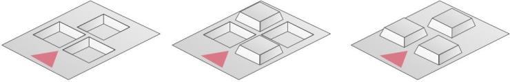
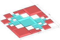
16 When use simple tools, robot must holds the simple tools at the start of a mission and carries them until the goal is reached Mission T1 :Traversing Obstacle Outline Traverse and negotiate the following obstacles individually or in combination The size of a robot determines which tasks to be executed. (1) Task T1-A :Crossing Ramps For S and M-sized robots (2) Task T1-B :Elevated ramps For S and M-sized robots (3) Task T1-C :Narrow Space For robots in all sizes (4) Task T1-D :Uneven Terrain(Chocolate&Waffle) For L-sized robots Obstacle Details (Type and shape) T1-A :Crossing Ramps S and M-sized robot Alternating hill terrain with 15 degree slope T1-B :Elevated Ramps S and M-sized robot A diagonal hill terrain with 15-degree ramps of varied height T1-C :Confined Space(Jungle gym) Robots in all sizes Traverse in continuously linked rectangular frames.(see figure and 7-3.2) 16
:Magnification factor of frame. Ratio(%) to a frame of standard width. Height (h): Height of a frame. Ratio to the width of the frame width W (=U S).")
17 Obstacle type, shape and symbol Symbol Type(J) - Standard width(u)- Mangnification Factor(S)-Height (h) Type:J Standard Width(U):Width of a basic rectangular frame. The unit is meter. Magnification Factor(S):Magnification factor of frame. Ratio(%) to a frame of standard width. Height (h): Height of a frame. Ratio to the width of the frame width W (=U S). Ex )J A frame with W=1m on one side and with W=1m height. Ex)J A frame with W=70cm on one side and with W=1.05m height. Figure 7-3.1:Frame 17

18 Figure 7-3-2:Continuous Frames T1-D :Uneven Terrain(Chocolate&Waffle) L-sized robot A mountain or hole, made by cutting a square(standard length L) pyramid horizontally at L*S/100 height from the base. See figure Obstacle Type, Shape and Symbol Obstacle type and symbol are as follows. Symbol Type(A or V) - Standard Width(L) - Height and Depth (S) Type:A:A-shaped mountain V:V-shaped hole Height and depth(s):ratio(%) of the height of a mountain or the depth of a hole to the standard lengths Ex)V-1-10 A hole with 1m on a side and 10cm depth 18


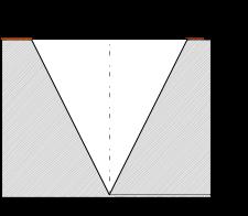
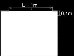
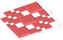
19 Uneven terrain is a combination of S = 10 mountains and holes(table:see 7.3.1) Table 7-3.1:Uneven Terrain(Chocolate & Waffle) L=1m S = 100 S = 10 A A A-1-10 V Table 7-3-3: A combination of uneven terrain 19
20 7.4. Mission T2 :Vehicle Inspection Outline Investigate inside and outside a vehicle and its surroundings. Investigation is to identify a target on the specified spot and report its findings Execute the following 3 tasks T2-1 Search victims and report their conditions. Open the door, identify targets and dummy targets inside and report T2-2 Investigate vehicle conditions. Identify targets placed outside of a vehicle and report T2-3 Investigate the surroundings of a vehicle(tunnel roof, wall and road surface). Identify targets placed around a vehicle (road surface) and report Mission T3 :Vehicle Inspection using Tools and Victim Extraction Outline Open or remove a door using specified tools to rescue victims left in a vehicle. A 15kg spreader is to be used as a tool Execute tasks in the following procedures. (1) T3-1 Grasp a tool (spreader). (2) T3-2 Execute one of the followings to rescue victims in a vehicle. (A) Cut the lock side of a door to open. (B) Cut both the lock and hinged sides of a door to open and remove the door. The following conditions are applied in executing the above task (A) and (B). Cutting position is indicated as a yellow triangle. A door weighs 18kg. 20
21 Hold for 10 seconds with pushing the head of a spreader vertically of 150N force against the cutting position. Reaction force resulting from the door breakage will be transmitted to the robot through the spreader. When the spreader head is placed in the right position and direction, the yellow indicator will appear adjacent to the spreader and turn into red in 3 seconds. Errors in coordinate position and direction are allowed up to ±30mm and ±5 respectively. (3) T3-3 Identify dummy targets in a vehicle, rescue victims inside and transfer to a designated area Mission T4 : Secure Route Outline Move or remove obstacles in the path and transfer to a designated area outside the path to secure the route (this is a task called removal). Transfer or stack obstacles onto a designated area. Shape, size and weight of obstacles differ according to tasks. Obstacles are either placed individually, in combination or in the stack. Basic shape of obstacles is L- or J- shaped and different in each task Obstacle Shape and Weight Table: shows the size and specific weight of L-shaped obstacles to transfer and reload, and Table: shows the shape and mass of obstacles to extract. Table 7-6.1:Size and Weight Density of obstacles to transfer and reload Shape Size(cm) Weight Density 21
22 L-shaped obstacles, with 50 the indicated length on a 1.5 L 25 side, made of 4 rectangular frames linked together 1 Different in each rectangular frames Table 7-6.2:Shape and mass of obstacles (circular cross section) to extract Shape Diameter of circular cross section (mm) Length (m) Length of Short Side (m) Angle (Degree ) Mass(kg) per 100mm diameter 1m length I L 90 Ratio of long side to 50 1 short side J 1 : 1 4 : Execute the following tasks individually or in combination. (1) T4-A Remove obstacles placed on a road surface. Following the procedure, move two combined obstacles to ensure the route. Ex. 1) Move one of the combined L-shaped obstacles to the left and the other to the right. Robot is required to remain in the passage (yellow area). 22


 T4-B Transfer or reload stacked obstacles Move stacked obstacles or transfer onto")
23 Ex.2) Pull forward one of the combined L-shaped obstacles and move to the left side designated area. Then pull the other one to the right. Robot is not allowed to enter no entry area (black and yellow area in the figure) including the space above. Robot is also required to remain in the passage (yellow area). (2) T4-B Transfer or reload stacked obstacles Move stacked obstacles or transfer onto another obstacle to ensure the route. Ex) Move an obstacle placed on the obstacles to another obstacle outside the passage. 23
 Extract horizontally (b) Extract vertically (c) Pull up vertically and extract horizontally (d) Extract by rotating the axis (e) Extract with rotation (4) T4-D Remove a vehicle out of a tunnel to")
24 (3) T4-C Extract Obstacles Remove obstacles buried in the wall, ground, vehicle and debris to clear a path. (a) Extract horizontally (b) Extract vertically (c) Pull up vertically and extract horizontally (d) Extract by rotating the axis (e) Extract with rotation (4) T4-D Remove a vehicle out of a tunnel to clear the path. L-size robot Table shows vehicle size and weight. Size (width length Weight height) (A) kg (B) ,500kg (C) ,000kg Table 7-6.3:Vehicle weight and mass 7.7. Mission T5 :Fire Extinguishment 24
 Door closed (b) Door opened Figure 7-7.")
 T5-1 Open the door of a fire extinguisher cabinet and pull out the hose. The weight of a hose is 0.275kg/m.")

25 Outline Extinguish fire in a tunnel with a firefighting equipment installed in a tunnel Figure shows the exterior of a fire extinguisher cabinet. (a) Door closed (b) Door opened Figure 7-7.1:Exterior of a fire extinguisher cabinet Task is executed in the following order. (1) T5-1 Open the door of a fire extinguisher cabinet and pull out the hose. The weight of a hose is 0.275kg/m. The weight of a hose coupling is 0.5kg. (2) T5-2 Pull out a nozzle and connect it to a hose. Pull out a nozzle installed in a firefighting equipment. Nozzle weighs 1kg. Insert the back end clamp of a hose into the rear edge of a nozzle until both fittings match (See the figure below). (3) T5-3 Open the valve of a fire extinguisher. 25
26 Rotate the valve 90 anticlockwise. Torque required to rotate a valve is 5Nm(a valve rotates with a minimum torque 5Nm). (4) T5-4 Move to the fire origin with holding a nozzle connected with a hose. Turn the nozzle toward the fire and extinguish fire. Spray water from a designated area (Move to the designated area). Rotate the lever attached to a nozzle to spray water. Torque required to rotate a lever is 2Nm(a lever rotates with a minimum torque 2Nm). Spraying a specified amount of water on the fire to extinguish. The flame will gradually spread once the task starts Mission T6 :Shoring and Breaching Outline Shoring and breaching of rubble on a vehicle to investigate inside of a vehicle. 26
 T6-1 Shoring M-size robot Move a shoring equipment to a designated area.")

27 Task is executed in the following order. (1) T6-1 Shoring M-size robot Move a shoring equipment to a designated area. Push the equipment into a specified point. Moment required to push the equipment is 25Nm with an obstacle as a pivot (The part moves with a minimum torque 25Nm) L-size robot Push the already assembled shoring equipment into a specified point. The weight of the assembled equipment for shorting is to be 50 to 200kg. 27

28 Push-in distance is to be 1 to 5m. (2) T6-2 Breaching Grasp a tool. Use a 30kg concrete boring drill. Drill a 10cm hole in diameter into rubble and the ceiling of a vehicle. Hold for a specified amount of time, pushing the head of the drill vertically with 300N force against the cutting position. Reaction force resulting from breakage will be transmitted to the robot through the tool. Errors in coordinate position and direction are allowed up to ±30mm and ±5 respectively. When the drill head is placed in the right position and direction, the yellow indicator will appear adjacent to the drill and turn into red in 3 seconds, which indicates the completion of drilling. (3) T6-3 Victim Identification Identify a dummy target in a vehicle through a drilled hole as in T6-2 28
29 29
World Robot Summit Call for Tenders: A Standard Robot Platform in Simulation for Tunnel Disaster Response and Recovery Challenge
 World Robot Summit Call for Tenders: A Standard Robot Platform in Simulation for Tunnel Disaster Response and Recovery Challenge The Japanese Ministry of Economy, Trade and Industry (METI) and the New
RoboCup Rescue Rulebook
 RoboCup Rescue Rulebook (as of 2017-07-21) Version 1.5 (with FAQ section) Overview of Changes from 2016 Changed the Best in Class certificates to have four classes: Best in Class Autonomy; Best in Class
Line Follower Enhanced Regulations
 Line Follower Enhanced Regulations 1. Generalities The Line Follower Enhanced competition s goal is finishing, in the shortest possible time, a track specially designed for this competition. A team does
Door window. Front door window, assembly overview
 64-50 Door window Front door window, assembly overview 1 - Window channel Pushed onto flange 2 - Door window Removing Page 64-52 Adjusting Page 64-53 3 - Door 4 - Outer window channel Pushed onto flange
Chapter 4. Accessible Routes
 ICC/ANSI A117.1-2003 401 General 401.1 Scope. Accessible routes required by the scoping provisions adopted by the administrative authority shall comply with the applicable provisions of Chapter 4. 402
SEMI-PRIVACY PANEL AND GATE INSTALLATION INSTRUCTIONS
 SEMI-PRIVACY PANEL AND GATE INSTALLATION INSTRUCTIONS 1 BEFORE YOU START, IT S IMPORTANT TO CHECK: That fence or the fence post footings do not exceed your lot lines of your property. If you can locate
TU Graz Robotics Challenge 2017
 1 TU Graz Robotics Challenge W I S S E N T E C H N I K L E I D E N S C H A F T TU Graz Robotics Challenge 2017 www.robotics-challenge.ist.tugraz.at Kick-Off 14.03.2017 u www.tugraz.at 2 Overview Introduction
MAVeC 19 Autobot Challenge
 Overview of the Challenge Name: TurtleBot3 Autobot Challenge Platform: TurtleBot3 MAVeC 19 Autobot Challenge Description: Autonomous Driving Mission Competition using ROS and TurtleBot3 platform Introduction
ROBOT KR 350. Installation, Connection, Exchange. Ro/Me/03/ en. 1of 26
 ROBOT KR 350 Installation, Connection, Exchange 1of 26 e Copyright KUKA Roboter GmbH This documentation or excerpts therefrom may not be reproduced or disclosed to third parties without the express permission
World Robot Olympiad 2018
 World Robot Olympiad 2018 Advanced Robotics Category Game Description, Rules and Scoring Version: Final Version January 15 th Table of Contents Introduction... 3 Important changes for Tetrastack 2018...
IEEE Open Milker Robot Version 1.1
 IEEE Open 2016 2017 Milker Robot Version 1.1 Sumary Introduction Goals The scenario The Field Cows Gloves Terrines The Milk Tank Zones Markers Lighting conditions Dimensions The Robot Rules Arena initial
Escape From ENGINEERING ISLAND KU High School Design
 Escape From ENGINEERING ISLAND KU High School Design Lego Mindstorms October 25, 2016 Competition Summary Teams will need to design, build, and program a survival vehicle using a Lego Mindstorms EV3 or
18600 Angular Momentum
 18600 Angular Momentum Experiment 1 - Collisions Involving Rotation Setup: Place the kit contents on a laboratory bench or table. Refer to Figure 1, Section A. Tip the angular momentum apparatus base on
SCIENCE OLYMPIAD. Mission Possible B Patrick Chalker m
 SCIENCE OLYMPIAD Mission Possible B 2016-17 1 Patrick Chalker patrickchalkerso@gmail.co m WHAT IS MISSION POSSIBLE? Students design, build, test & document a Rube Goldberg-like device Device made of a
580A Automatic Cable Tying Machine 580A
 Automatic Cable Tying Machine 580A Contenido Regular Information...3 Technical parameters:...5 Operation Instruction....6 Trouble Shooting....8 Maintenance....9 After-sales Service...9 Safety Instructions....10
3.2.3 Rear Door Window and Quarter Window Carrier Assembly
 Tighten all bolts. Tighten bolts marked -1- and -2- in specified sequence. Tightening torque: 8 Nm Remaining bolts can be tightened in any sequence. Insert door window -3- through window recess without
1. Arena 1.1. Description
 1. Arena 1.1. Description 1.1.1. The arena is modular by tiles, which can be used to make an endless number of different courses for the robots to traverse and also provides with the ability to add new
incorrect use or handling that exceeds normal operating limits.
 User s Manual Wall mount unit for projectors Model name HAS-WM06 Thank you for purchasing a wall mount unit specially designed for Hitachi projectors. Be sure to read this manual and the User s Manual
FLIP TARP SINGLE & DOUBLE UNDERBODY TRAILERS
 1-800-248-7717 1002 N. 15th Street, Middlesboro, KY 40965 FLIP TARP SINGLE & DOUBLE UNDERBODY TRAILERS INSTALLATION INSTRUCTIONS Congratulations on your purchase of a Mountain Flip Tarp Trailer system.
TM12 ASSEMBLY INSTRUCTIONS
 TM12 ASSEMBLY INSTRUCTIONS Congratulations on purchasing the finest purple martin house available. Nature House Brand houses are the proven leader in aluminum martin housing for over half a century. After
LOCKN LOAD FIRST TIME INSTALLATION
 LOCKN LOAD TM TRACK MOUNTING KIT ISUZU MU-X 2013+ LS-M & LS-U MODELS ONLY 3 BAR TRACK HEAVY DUTY ROOF RACK SYSTEM MAX VEHICLE ROOF LOAD RATING: 100KG TOTAL LOAD EQUALS WEIGHT OF ROOF RACKS + ACCESSORIES
Students will design, program, and build a robot vehicle to traverse a maze in 30 seconds without touching any sidewalls or going out of bounds.
 Overview Challenge Students will design, program, and build a robot vehicle to traverse a maze in 30 seconds without touching any sidewalls or going out of bounds. Materials Needed One of these sets: TETRIX
CREATING FREE SURFACES ON HARD ROCKS USING ABRASIVE SUSPENSION WATER JET MANIPULATORS
 2009 American WJTA Conference and Expo August 18-20, 2009 Houston, Texas Paper CREATING FREE SURFACES ON HARD ROCKS USING ABRASIVE SUSPENSION WATER JET MANIPULATORS Song S. Han Institute of Construction
Fig. 2 DORMA-Glas Stand/Issue 02/03 Seite/Page 1/7
 FSW Installation instructions Track rail 75 x 72 mm 1. Ceiling substructure and installation of the track rail (Fig. 1): The track rail must be bolted over its entire length (including the stacking track
Wooden Frame Type Instruction Manual
 Wooden Frame TypeInstruction Manual Thank you for selecting our product. Before starting installation, please read this manual thoroughly to ensure correct installation. Please keep this manual at hand
Weather Station for KNX
 Weather Station for KNX Installation and Adjustment Product description... 3 Technical data... 3 PCB layout...5 230 V AC version... 5 24 V DC version... 6 Installation and commissioning... 7 Location...
RoboCup Rescue Rulebook. Overview of Changes from Concept for RoboCup Rescue. (as of ) Version 2.3 (with FAQ section)
 Version 2.3 (with FAQ section)") RoboCup Rescue Rulebook (as of 2019-01-12) Version 2.3 (with FAQ section) Overview of Changes from 2017 Changed timing and autonomy points: 23 minute runs for everybody, double points for autonomy, 1.5
RoboCup Rescue Rulebook (as of 2019-01-12) Version 2.3 (with FAQ section) Overview of Changes from 2017 Changed timing and autonomy points: 23 minute runs for everybody, double points for autonomy, 1.5
INTERMEDIATE LEVEL MEASUREMENT
 INTERMEDIATE LEVEL MEASUREMENT TABLE OF CONTENTS Format & Background Information...3-6 Learning Experience 1- Getting Started...6-7 Learning Experience 2 - Cube and Rectangular Prisms...8 Learning Experience
1 of 2 3/3/2017 4:49 PM
 1 of 2 3/3/2017 4:49 PM Front Door Window, Assembly Overview 1 - Window guide - Inserted on flange 2 - Door 3 - Inner window recess seal - Inserted on flange 4 - Bolt - 20 Nm 5 - Carrier assembly - Window
ROBOTICS DESIGN CHALLENGE. Colorado TSA State Conference BUILDING COLLAPSE
 ROBOTICS DESIGN CHALLENGE Colorado TSA State Conference 2018-2019 BUILDING COLLAPSE Overview of Design Challenge changes from 2017-2018: 1) Removal of packed debris socks and replaced with a fallen staircase
Figure 1. Calculate the total clockwise moment of the weight of the diving board and the weight of the girl about Point A. Give the unit
 Q1.(a) Figure 1 shows a girl standing on a diving board. Figure 1 Calculate the total clockwise moment of the weight of the diving board and the weight of the girl about Point A. Give the unit. Total clockwise
N. 15th Street, Middlesboro, KY FLIP TARP DUMP BODY INSTALLATION INSTRUCTIONS
 1-800-248-7717 1002 N. 15th Street, Middlesboro, KY 40965 FLIP TARP DUMP BODY INSTALLATION INSTRUCTIONS Congratulations on your purchase of a Mountain Flip Tarp Dump Body tarping system. With tarping systems
BY ALIEN TECHNOLOGIES CORP
 BY ALIEN TECHNOLOGIES CORP Assembly Instructions TopLift Pros YOU MAY ALSO REVIEW OUR ASSEMBLY VIDEO, PLAY AND PAUSE AT YOUR CONVENIENCE. JUST VISIT US AT WWW.TOPLIFTPROS.COM AND GO TO Customer Support
Operators Manual (Manual A)
") CD201 SINGLE COLUMN CARD DISPENSER Operators Manual (Manual A) Contents A1 Scope... 1 A2 Specifications... 1 A3 Installation... 2 3.1 Unpacking and inspection... 2 3.2 Opening and closing the door... 2
CD201 SINGLE COLUMN CARD DISPENSER Operators Manual (Manual A) Contents A1 Scope... 1 A2 Specifications... 1 A3 Installation... 2 3.1 Unpacking and inspection... 2 3.2 Opening and closing the door... 2
LOCKN LOAD FIRST TIME INSTALLATION
 LOCKN LOAD TM TRACK MOUNTING KIT MITSUBISHI TRITON MQ DUAL CAB 2015+ 2 BAR TRACK HEAVY DUTY ROOF RACK SYSTEM MAX VEHICLE ROOF LOAD RATING: 100KG TOTAL LOAD EQUALS WEIGHT OF ROOF RACKS + ACCESSORIES + CARGO
SLIDE 06 Solutions Document/Installation Manual
 SLIDE 06 Solutions Document/Installation Manual 1 The Slide 06 door system from 3form is a completely unframed panel door that uses the same sophisticated, tried-and-true rollers and track as Slide 05.
PHYS 241 FINAL EXAM December 11, 2006
 1. (5 points) Light of wavelength λ is normally incident on a diffraction grating, G. On the screen S, the central line is at P and the first order line is at Q, as shown. The distance between adjacent
IEEE Latin American Robotics Competition for Student. RULES OF SEK Category 2015/2016 Version 1.1 March, 2015
 IEEE Latin American Robotics Competition for Student INTRODUCTION RULES OF SEK Category 2015/2016 Version 1.1 March, 2015 In a galaxy very far from the planet Earth, three nations have been living harmoniously
How To Measure Your Finished Opening
 3000 Series Bifold Doors How To Measure Your Finished Opening MEASURE FROM RIGHT TO LEFT 2 PLACES (WIDTH) MEASURE FROM TOP TO BOTTOM 2 PLACES (HEIGHT) Tools Required for Assembly: Tools Needed: Phillips
Catapult Engineering
 With support from Oxfordshire County Council, Science Oxford is pleased to present; Catapult Engineering The Physics of Siege Weapons STEM Club Resource Pack Introduction: Catapult engineering involves
PolyDock MAY RESULT IN PERSONAL INJURY OR DEATH AND WILL INVALIDATE THE
 Floating PolyDock PolyDock Instructions and Safety Tips Floating PRODUCT PolyDock ASSEMBLY INSTRUCTIONS Instructions and Safety Tips - PUT SAFETY FIRST - PUT SAFETY FIRST 1. To avoid the risk of personal
Instruction Manual. Manual Furniture Mover. Note: Owner/Operator must read and understand this instruction manual before using the furniture mover.
 Instruction Manual Manual Furniture Mover Note: Owner/Operator must read and understand this instruction manual before using the furniture mover. I - Contents 1. Application 2 Specifications 3.Assembly
Installation Instructions
 by Plato Woodwork Installation Instructions Plato Woodwork, Inc. 200 Third Street SW P.O. Box 98 Plato, MN 55370 www.platowoodwork.com 800.328.5924 SECTION GUIDE GETTING STARTED PAGE # Installation Methods...
Leveling Foot RB210. Leg Extender RLT66
 Landing for Right & Left Turn R342 ITEMS # 0254049, 0254061, 0254072, 0254076, 0016567, 0254099, 0254110, 0054116, 0254117, 0254126, 0254140, 0254150, 0254156 CUSTOM ACCESS RAMP SYSTEM MODELS # R100, R242,
Theme & Rules. ABU Asia-Pacific Robot Contest 2009 Tokyo. Host Organising Committee. September 1st 2008
 ABU Asia-Pacific Robot Contest 2009 Tokyo Theme & Rules Travel Together for the Victory Drums September 1st 2008 ABU Asia-Pacific Robot Contest 2009 Tokyo Host Organising Committee 1 Contents Towards the
Whirlygigs for Sale! Rotating Two-Dimensional Figures through Space. LESSON 4.1 Skills Practice. Vocabulary. Problem Set
 LESSON.1 Skills Practice Name Date Whirlygigs for Sale! Rotating Two-Dimensional Figures through Space Vocabulary Describe the term in your own words. 1. disc Problem Set Write the name of the solid figure
Product must be installed as shown using the screws and brackets provided. Use of incorrect hardware could result in damage to the product.
 General Notes These installation instructions are intended to be comprehensive for a typical Keyeira/Presto configuration. Your configuration may differ. If you have questions contact Geiger Customer Service
Easy Step by Step Manual
 Easy Step by Step Manual Teletower Mini XL Wall-Floor installation The tower packages #1-#2-#3 Open Base Package #1 for the main tower parts. Here you see the three tower tubes (H-Head, M-Middle, F-Feed)
Chapter 2: Dimensioning Basic Topics Advanced Topics Exercises
 Chapter 2: Dimensioning Basic Topics Advanced Topics Exercises Dimensioning: Basic Topics Summary 2-1) Detailed Drawings 2-2) Learning to Dimension 2-3) Dimension Appearance and Techniques. 2-4) Dimensioning
Dowelling joints with VS 600
 No. 112 Dowelling joints with VS 600 A Description Dowelling joints with round dowels (in addition to flat dowels) are part of the standard wood joints in furniture manufacture. This joint is very stable.
Sentinel Series Cigar Humidor End Tables
 Sentinel Series Cigar Humidor End Tables Assembly Instructions Models: Sentinel 500, 1000 and 1500 Style: Contemporary SENTINEL ASSEMBLY INSTRUCTIONS Congratulations! You have purchased a superior cigar
Hollywood Swing Away 2 and 4 Bike Racks Assembly and Installation Guide
 Hollywood Swing Away 2 and 4 Bike Racks Assembly and Installation Guide Tools Required: two adjustable wrenches, pliers, ¾ socket wrench recommended Note: please do assembly near your vehicle as you Can
CertainTeed INSTALLATION GUIDE SIMTEK FENCE PRODUCTS. Fence Installation Guide 3', 4' & 6' High
 CertainTeed INSTALLATION GUIDE SIMTEK FENCE PRODUCTS Fence Installation Guide 3', 4' & 6' High INSTALLATION GUIDE These instructions are designed to assist both professional installers and do-it-yourselfers
MSR/MSB Mechanical Setting Tool
 Tech Unit No: 0620000004 Revision: B Approved By: Quality Engineer Date: 2014-12-16 MSR/MSB Mechanical Setting Tool FEATURES: Special designed Bow Spring provides positive control and allows one size Mechanical
General Guidelines:
 ASSEMBLY INSTRUCTIONS Congratulations on your new Patriot Dock purchase. This manual contains instructions to assemble basic dock configurations for use at typical residential shoreline application. Please
JK XY LJ LJ ZX KL KL YZ LJ KL YX KJ. Final Exam Review Modules 10 16, 18 19
 Geometry Final Exam Review Modules 10 16, 18 19 Use the following information for 1 3. The figure is symmetric about the x axis. Name: 6. In this figure ~. Which statement is not true? A JK XY LJ ZX C
Cisco Aironet 2.4-GHz/5-GHz 8-dBi Directional Antenna (AIR-ANT2588P3M-N)
") Cisco Aironet.4-GHz/5-GHz 8-dBi Directional Antenna (AIR-ANT588P3M-N) This document outlines the specifications for the Cisco Aironet AIR-ANT588P3M-N.4/5-GHz 8-dBi 3-Port Directional Antenna with N-connectors
Cisco Aironet.4-GHz/5-GHz 8-dBi Directional Antenna (AIR-ANT588P3M-N) This document outlines the specifications for the Cisco Aironet AIR-ANT588P3M-N.4/5-GHz 8-dBi 3-Port Directional Antenna with N-connectors
Preference Collection 5580 Treatment Console INSTALLATION GUIDE
 Preference Collection 5580 Treatment Console INSTALLATION GUIDE 0 WARNING Failure to install the 5580 as described in this installation guide may cause the unit to collapse, resulting in serious injury
ENGINEERING DRAWING. UNIT III - Part A
 DEVELOPMENT OF SURFACES: ENGINEERING DRAWING UNIT III - Part A 1. What is meant by development of surfaces? 2. Development of surfaces of an object is also known as flat pattern of the object. (True/ False)
Holden Colorado Isuzu DMAX - RIDB1
 Holden Colorado Isuzu DMAX - RIDB1 Fit Time: 1.5 Hours IMPORTANT INFORMATION Maximum carrying capacity: Suitable Pioneers On Road Cargo Allowance Off Road Cargo Allowance Static Allowance Roof Allowance
A Generic Sauna Room Assembly Manual
 A Generic Sauna Room Assembly Manual Parts List Exterior 1. Ceiling Assembly 2. Wall Elements 3. Exterior Mouldings 4. Top Exterior Mouldings 5. Bottom Exterior Mouldings 6. Main Base Frame 7. ABS Bolt
THE ROGUE TM FUNSLIDE TM
 THE ROGUE TM FUNSLIDE TM ASSEMBLY AND INSTALLATION INSTRUCTIONS * * C A U T I O N * * S.R. SMITH ROGUE TM FUNSLIDES TM ARE MANUFACTURED FOR INSTALLATION AND USE ON RESIDENTIAL INGROUND POOLS ONLY. ROGUE
figure 1 figure 2 INSTRUCTIONS AND TIPS FOR THE INSTALLATION OF THE HC MODEL CINEMA MIRROR x = y
 CONSIDERATIONS 1 Cinema Mirror is an active optic set to be installed in false ceilings hiding the projection equipment, and that through a pulsation it opens a floodgate of 335x335 mm., allowing the projection
GATE INSTALLATION INSTRUCTIONS
 GATE INSTALLATION INSTRUCTIONS 1) Ensure posts for gate are fully installed. Posts need to be securely fastened to decking or concrete such that they will not sag with weight of the gate. For a single
the slim retracting clothesline product manual
 &6 the slim retracting clothesline product manual for 4 and 6-line models HLS0046_4-6 line_owners Manual_v6.indd 1 2 Introduction Congratulations Congratulations on the purchase of your new Hills slim
C A R I B B E A N E X A M I N A T I O N S C O U N C I L REPORT ON CANDIDATES WORK IN THE SECONDARY EDUCATION CERTIFICATE EXAMINATION MAY/JUNE 2010
 C A R I B B E A N E X A M I N A T I O N S C O U N C I L REPORT ON CANDIDATES WORK IN THE SECONDARY EDUCATION CERTIFICATE EXAMINATION MAY/JUNE 2010 TECHNICAL DRAWING GENERAL PROFICIENCY Copyright 2010 Caribbean
Selfsat TOP. Satellite Flat Antenna with Lift and Rotation Unit. Manual
 Selfsat TOP Satellite Flat Antenna with Lift and Rotation Unit Manual 1. Contents: www.camos-multimedia.com Quantity Description 1 Antenna Selfsat HD 10 1 Lift and Rotation Unit (pre-assembled) 2 Ceiling
DISCO DICING SAW SOP. April 2014 INTRODUCTION
 DISCO DICING SAW SOP April 2014 INTRODUCTION The DISCO Dicing saw is an essential piece of equipment that allows cleanroom users to divide up their processed wafers into individual chips. The dicing saw
D3976 RECESSED EXIT INSTALLATION INSTRUCTIONS
 PACKAGE CONTENTS PRODUCT MUST BE INSTALLED ACCORDING TO ALL APPLICABLE BUILDING AND LIFE SAFETY CODES TEMPLATE INSTALLATION INSTRUCTIONS STRIKE HAND TOOL 5/32 HEX KEY ROD END CAPS EXIT DEVICE CRANK ARM
Siding Systems NOVIKSTONETM DS DRY STACK STONE INSTALLATION GUIDE
 Siding Systems NOVIKSTONETM DS DRY STACK STONE GENERAL INFORMATION CAUTION: REMEMBER THAT POLYMER UNDERGOES EXPANSION/CONTRACTION DUE TO VARIATIONS IN TEMPERATURE. THE FOLLOWING INSTRUCTIONS WILL ALLOW
Installation Manual for Gate Guard
 Installation Manual for Gate Guard Fast Opening Barrier Gate for Emergencies and Contra Flow Innovative safety technology from SGGT of Germany TABLE OF CONTENTS Page Number Preface 3 Introduction 3 System
General Wood Shop Notes
 General Wood Shop Notes Restricted Materials No METAL or BONE of any kind on any machine or in the room o See additional restrictions individual machine All reclaimed and other than new lumber must be
World Robot Summit. January 2018 Ministry of Economy, Trade and Industry (METI) New Energy and Industrial Technology Development Organization (NEDO)
 New Energy and Industrial Technology Development Organization (NEDO)") (Appendix 1) World Robot Summit January 2018 Ministry of Economy, Trade and Industry (METI) New Energy and Industrial Technology Development Organization (NEDO) Concept The World Robot Summit (WRS) is
(Appendix 1) World Robot Summit January 2018 Ministry of Economy, Trade and Industry (METI) New Energy and Industrial Technology Development Organization (NEDO) Concept The World Robot Summit (WRS) is
System FS Duo Mounting Instruction. 1 General 2. 2 Pile driving 3. 3 Mounting the individual assembly groups 4. 4 Torque specifications 7
 System FS Duo Mounting instructions CONTENTS Page 1 General 2 2 Pile driving 3 3 Mounting the individual assembly groups 4 4 Torque specifications 7 5 Module mounting 8 6 Tolerances 8 1 / 8 1 General 1.1
Cozmo Clench(wildcard)
") Cozmo Clench(wildcard) TASK: The team has to build a manually controlled bot which can do the simple task of gripping blocks and putting them in target zones so that it can complete the route by overcoming
Cozmo Clench(wildcard) TASK: The team has to build a manually controlled bot which can do the simple task of gripping blocks and putting them in target zones so that it can complete the route by overcoming
ASSEMBLY INSTRUCTION FOR WYTHE BURLED WOOD BAR
 ASSEMBLY INSTRUCTION FOR WYTHE BURLED WOOD BAR IMPORTANT SAFETY INSTRUCTIONS: Please read all instructions carefully before assembling. For your safety, assembly by two or more adults is strongly recommended.
TITAN2-EDGE Public Access Computer Station Dual Track
 TITAN2-EDGE Public Access Computer Station Dual Track TITAN2-EDGE Rev A 6/17 Model TITAN2-EDGE ASSEMBLY AND ADJUSTMENT TITAN2-EDGE PARTS AND TOOLS PLEASE REVIEW these instructions before beginning the
Professional welding tables
 Professional welding tables WELDING TABLES ACCESSORIES STOPS PRESSURERS/CLAMPS/GRIPS BOLTS weldingmaster We are the manufacturers of modular welding tables. Weldingmaster tables are highly innovative products,
2015 Maryland State 4-H LEGO Robotic Challenge
 Trash Talk Utilizing Trash to Power the World 2015 Maryland State 4-H LEGO Robotic Challenge Through Trash Talk, 4-H members involved in robotics will create LEGO robots that complete tasks related to
Cut-True 16M Manual Paper Cutter
 Cut-True 16M Manual Paper Cutter 2/2013 OPERATOR MANUAL FIRST EDITION TABLE OF CONTENTS TOPIC PAGE Specifications 1 Safety Guidelines 1 Assembly 2 Overview 3 Description of Equipment Parts 3-4 Operation
Fire Fighting. Objective. Robot. Fire Fighting. Name of Event: Robots per Team: 1
 Fire Fighting Name of Event: Robots per Team: 1 No. of Players: Robot Control: Event Summary: Fire Fighting 2 players/team Autonomous This is an autonomous robot competition between 2 teams to extinguish
Omarshauntedtrail.com. Obtained from. How-To build columns with propane flames. Halloween Props
 Halloween Props http://www.angelfire.com/goth/clintshalloweenprops/columns.html How-To build columns with propane flames. Parts 2x4 Boards (I used an old fence under the free section of craigslist.org)
MODUS 770 AND MODUS 1280 (FLAT PACK) OPERATIONAL, ASSEMBLY & FIXING INSTRUCTION LEAFLET
 OPERATIONAL, ASSEMBLY & FIXING INSTRUCTION LEAFLET") MODUS 770 AND MODUS 1280 (FLAT PACK) TM TM OPERATIONAL, ASSEMBLY & FIXING INSTRUCTION LEAFLET NOTE: Ensure that all relevant personnel read the points listed below and that a copy is passed on to staff
MODUS 770 AND MODUS 1280 (FLAT PACK) TM TM OPERATIONAL, ASSEMBLY & FIXING INSTRUCTION LEAFLET NOTE: Ensure that all relevant personnel read the points listed below and that a copy is passed on to staff
RoboCupJunior Rescue Maze Rules 2016
 RoboCupJunior Rescue Maze Rules 2016 RoboCupJunior Rescue - Technical Committee 2016 Fredrik Löfgren (Sweden) CHAIR, fredrik@eaproduktion.se Roberto Bonilla (Mexico), rbonilla@mytech.zone Naomi Chikuma
2005 Galois Contest Wednesday, April 20, 2005
 Canadian Mathematics Competition An activity of the Centre for Education in Mathematics and Computing, University of Waterloo, Waterloo, Ontario 2005 Galois Contest Wednesday, April 20, 2005 Solutions
Installing Your Electronic Deadbolt
 Ultra Security Plus Electronic Deadbolt Installation Instructions http://www.hberger.com/video-gallery/electronic-deadbolt New Installation Lock Location Preparation (Skip this section if you door has
2018 Border Challenge Robotics Competition
 2018 Border Challenge Robotics Competition https://borderchallenge.weebly.com/ Table of Contents Section 1 Introduction... 2 Section 2 The Robot... 2 Robot Overview... 2 Robot Rules... 2 Section 3 The
WARNING. Read and become familiar with this manual BEFORE operating unit.
 Covered by one or more of the following patents: 3,828,942 5,368,429 5,586,619 5,984,605 7,556,464 7,726,901 Other patents pending. OPERATOR S MANUAL For Model 439 WARNING Read and become familiar with
OPEN PICKET PANEL AND GATE INSTALLATION INSTRUCTIONS
 For All Your Vinyl Fencing Needs OPEN PICKET PANEL AND GATE INSTALLATION INSTRUCTIONS 1 BEFORE YOU START, IT S IMPORTANT TO CHECK: That fence or the fence post footings do not exceed your lot lines of
Linear Hook- on Worksurfaces
 Linear Hook- on Worksurfaces Linear Hook-On Worksurfaces come in three depths and seven lengths. Different worksurfaces have different reqirements for installation that are outlined below. 27 inch deep
ClearSpan End Frame Kit 26' Wide x 12' High
 ClearSpan End Frame Kit 26' Wide x 12' High Diagram shows the end frame kit for an end wall without a door. (Door and end panel are purchased separately.) Rafter and struts shown in the above diagram are
Optical Cable Entry Facility (OCEF) Installation Instructions
 Installation Instructions") Instruction Sheet 860380690 Uniprise Solutions Optical Cable Entry Facility (OCEF) Installation Instructions General The Optical Cable Entry Facility (OCEF) cabinets store optical fiber splices between
Instruction Sheet 860380690 Uniprise Solutions Optical Cable Entry Facility (OCEF) Installation Instructions General The Optical Cable Entry Facility (OCEF) cabinets store optical fiber splices between
Advance Steel. Tutorial
 Advance Steel Tutorial Table of contents About this tutorial... 7 How to use this guide...9 Lesson 1: Creating a building grid...10 Step 1: Creating an axis group in the X direction...10 Step 2: Creating
Contractors Rack Assembly and Installation Instructions
 Part # 18601 & 16601 Contractors Rack Assembly and Installation Instructions 4751 Littlejohn St. Unit A, Baldwin Park, CA 91706 Page 1 of 12 11/13/08 Thank you for purchasing the Paramount Restyling Contractors
ASSEMBLY INSTRUCTIONS FOR SOFTOP SHADE COVER
 ASSEMBLY INSTRUCTIONS FOR SOFTOP SHADE COVER Our unique assembly process quickly transforms individual pieces into a finished structure that will give you a lifetime of service. Great care has been taken
«RELAY RACE» CONTEST RULES
 «RELAY RACE» CONTEST RULES Version 3.0 dated 20 July, 2017 Contents 1. General provisions... 2 1.1. Task Description... 2 2. Field, Line and Relay Baton Specifications... 2 3. Robot Specifications... 3
INSTALLATION INSTRUCTIONS REPLACING EXISTING DEADBOLT ASSEMBLY
 INSTALLATION INSTRUCTIONS REPLACING EXISTING DEADBOLT ASSEMBLY A B C L M N D E F G O P Q H I J Tools provided in Amesbury installation kit: (A) door router fixture, (B) doorframe router fixture, (C) ½
Operating Manual. for CUTTING, PERFORATING, BENDING SLB120
 Operating Manual for CUTTING, PERFORATING, BENDING SLB120 31040\B06eng 0896 0 Contents 1. Scope of delivery... 1 2. Technical specifications... 1 3. Applications... 1 4. Commissioning... 2 5. Cutting...
RoboCupJunior Rescue B Rules 2012
 RoboCupJunior Rescue B Rules 2012 RoboCupJunior Rescue - Technical Committee 2012 Damien Kee (Australia), damien@domabotics.com Kate Sim (UK), kateasim@btinternet.com Naomi Chikuma (Japan) mymama_8888@yahoo.co.jp
Station 0 -Class Example
 Station 0 Station 0 -Class Example The teacher will demonstrate this one and explain the activity s expectations. Materials: Hanging mass string Procedure Hang a 1 kilogram mass from the ceiling. Attach