RE-S1 Operator s Manual
|
|
|
- Aubrey Hart
- 5 years ago
- Views:
Transcription
1
2
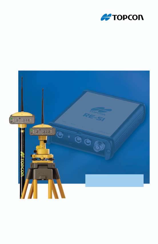
3 P O S I T I O N I N G S Y S T E M S RE-S1 Operator s Manual Part Number Rev A Copyright Topcon Positioning Systems, Inc. September, 2006 All contents in this manual are copyrighted by Topcon. All rights reserved. The information contained herein may not be used, accessed, copied, stored, displayed, sold, modified, published, or distributed, or otherwise reproduced without express written consent from Topcon.
4 Terms and Conditions Thank you for buying this Topcon product. This document has been prepared to assist you with the care and operation of the product and its use is subject to the following. USE This product is designed to be used by a professional. The user should have a good knowledge of the safe use of the product and implement the types of safety procedures recommended by the local government protections agency for both private use and commercial job sites. Copyrights All information contained in this Manual is the intellectual property of, and copyrighted material of Topcon Positioning Systems (TPS). All rights are reserved. You may not use, access, copy, store, display, create derivative works of, sell, modify, publish, distribute, or allow any third party access to, any graphics, content, information or data in this Manual without Topcon s express written consent and may only use such information for the care and operation of your product. The information and data in this Manual are a valuable asset of TPS and are developed by the expenditure of considerable work, time and money, and are the result of original selection, coordination and arrangement by TPS. Trademarks The information in this manual is a copyright of Topcon and is for use only with the product. HiPer, RE-S1, and Topcon are trademarks or registered trademarks of Topcon Positioning Systems, Inc. Other product and company names mentioned herein may be trademarks of their respective owners. DISCLAIMER OF WARRANTY EXCEPT FOR ANY WARRANTIES IN AN APPENDIX OR A WARRANTY CARD ACCOMPANYING THE PRODUCT, THIS MANUAL AND THE PRODUCTS ARE PROVIDED AS-IS. THERE ARE NO OTHER WARRANTIES. TPS DISCLAIMS ANY IMPLIED WARRANTY OF MERCHANTABILITY OR FITNESS FOR ANY PARTICULAR USE OR PURPOSE. TPS AND ITS DISTRIBUTORS SHALL NOT BE LIABLE FOR TECHNICAL OR EDITORIAL ERRORS OR OMISSIONS CONTAINED HEREIN; NOR FOR INCIDENTAL OR CONSEQUENTIAL DAMAGES RESULTING FROM THE FURNISHING, PERFORMANCE OR USE OF THIS MATERIAL OR THE PRODUCT. SUCH DISCLAIMED DAMAGES INCLUDE BUT ARE NOT LIMITED TO LOSS OF TIME, LOSS OR DESTRUCTION OF DATA, LOSS OF PROFIT, SAVINGS OR REVENUE, OR LOSS OF THE PRODUCT S USE. IN ADDITION TPS IS NOT RESPONSIBLE OR LIABLE FOR DAMAGES OR COSTS INCURRED IN CONNECTION WITH OBTAINING SUBSTITUTE PRODUCTS OR SOFTWARE, CLAIMS BY OTHERS, INCONVENIENCE, OR ANY OTHER COSTS. IN ANY EVENT, TPS SHALL HAVE NO LIABILITY FOR DAMAGES OR OTHERWISE TO YOU OR ANY OTHER PERSON OR ENTITY IN EXCESS OF THE PURCHASE PRICE FOR THE PRODUCT. Website and Other Statements No statement contained at the TPS website (or any other website) or in any other advertisements or TPS literature or made by an employee or independent contractor of TPS modifies these Terms and Conditions (including the Software license, warranty and limitation of liability). Safety Improper use of the Product can lead to injury to persons or property and/or malfunction of the product. The product should only be repaired by authorized TPS warranty service centers. Users should review and heed the safety warnings in Manual. Miscellaneous The above Terms and Conditions may be amended, modified, superseded, or canceled, at any time by TPS. The above Terms and Conditions will be governed by, and construed in accordance with, the laws of the State of California, without reference to conflict of laws. All information, illustrations, and applications contained herein are based on the latest available information at the time of publication. Topcon reserves the right to make product changes at any time without notice. ECO#2853
5 TOC Table of Contents Chapter 1 Introduction... 1 Getting Acquainted... 2 RX/TX LED... 2 Ports... 3 Radio Modem Antenna... 3 Standard Kit Cables and Power Supply... 4 Chapter 2 RE-S1 Configuration... 5 Installing Modem-TPS... 5 Configuring the RE-S1 as a Repeater... 6 Appendix A Specifications... 9 Appendix B Regulatory Information and Safety Warnings FCC Compliance Canadian Emissions Labeling Requirements Community of Europe Compliance WEEE Directive Safety and Usage Warnings Appendix C Warranty Terms P/N i
6 Table of Contents Notes: ii RE-S1 Operator s Manual
7 Chapter 1 Introduction The RE-S1 is a 1W radio extension system using 915+ spread spectrum technology. The RE-S1 can be used to enhance the following survey-related systems: As a stand-alone repeater to increase the range between a Base and Rover in spread spectrum systems, such as with the GR-3 or HiPer Lite+ GPS systems. As a transmit/receive external 915+ radio for any Base system, such as with the GB or Legacy series GPS receiver. Obstructions such as buildings, terrain, trees, etc greatly affect the usability and range of any radio system. The RE-S1 provides radio repeater capabilities and increase the operational range and effectivity of the system in unfavorable environments. NOTE The RE-S1 simply extends the operational range of a spread spectrum system. It does not increase range beyond the system s OAF limitations. PWR RX/TX A C MODEM ANT Figure 1. RE-S1 P/N
8 Introduction Getting Acquainted The RE-S1 is a transmit/receive/repeat 915+ spread spectrum radio modem. The RE-S1 is compatible with existing Topcon spread spectrum radio systems (some older HiPer models may need a radio modem upgrade), as well as Topcon base stations. Simple features allow the RE-S1 to be easily adaptable to any situation, and make it easy to use. RX/TX LED The RX/TX LED provides the following indications for the modem: Green flashes the modem is in receive mode and is searching for radio link. Green solid a radio link has been established. Green solid with Red flash the modem is receiving. Red solid the modem is in transmit mode. Red flashes an improper configuration has been detected. RX/TX LED Figure 2. RE-S1 Receive/Transmit LED LED notes: The RX/TX LED will be solid green with a red flash when the Base receiver is within radio range of the repeater system. The red flash indicates the following: A data packet has been received from the Base. A data packet has been transmitted from the repeater system. If the RX/TX LED flashes green for an extended period of time, check the following: The repeater s distance from the Base. 2 RE-S1 Operator s Manual
9 Getting Acquainted The channel of the RE-S1, Base, and Rover. The protocol of the RE-S1, Base, and Rover (FH915 Plus). Ports The RE-S1 has the following ports: Power Port used to connect the repeater an external power source. Serial Ports A and C used for communication between the repeater and an external device (computer or controller). Modem Antenna Port provides connection to a spread spectrum reverse TNC radio antenna to receive/transmit a radio signal. Power Port A Port C Modem Antenna Port Figure 3. RE-S1 Ports Radio Modem Antenna The spread spectrum modem antenna is a reverse polarity TNC RF connection (p/n ). SS Antenna Figure 4. Modem Antenna P/N
10 Introduction Standard Kit Cables The standard RE-S1 package includes communication and power cables for configuring the repeater and providing a power to the repeater. Table 1-1 lists the cables included in the package. Table 1-1. RE-S1 Standard Package Cables Cable Description Power cable, power port-to-sae Connects the repeater and the power supply unit via SAE connectors for battery charging. Body of connector is red. p/n Cable Illustration Alligator clips-to-sae cable Connects the repeater to a mobile external power source. p/n SAE-to-SAE extension cable Connects the SAE ends of two cables together. For example from the alligator clips to the charging cable. p/n Serial cable Connects the repeater to an external device (controller or computer) for modifying the configuration. Body of connector is black. p/n RE-S1 Operator s Manual

. Figure 5.")
11 Chapter 2 RE-S1 Configuration Once the RE-S1 is configured, it simply needs to be connected to a power source to begin operating. Installing Modem-TPS Modem-TPS is a configuration program for the radio modem board inside the unit. Modem-TPS is available from the TPS website or on the GPS+ CD. Computer requirements for Modem-TPS are: Windows 98 or newer and an RS-232C port. Use Modem-TPS version 2.0 or newer to correctly configure the RE-S1. 1. Navigate to the location of the Modem-TPS program and doubleclick the Setup.exe icon. 2. Keep the default installation location or select a new location. Click Finish (Figure 5). Figure 5. Select Modem-TPS Installation Location and Install 3. Click OK to complete the installation (Figure 6 on page 6). P/N

12 RE-S1 Configuration 4. If desired, create a shortcut on the computer s desktop for quick access to Modem-TPS (Figure 6). Figure 6. Installation Complete and Shortcut To uninstall Modem-TPS, use the Start menu on your computer: Click Start Programs Modem-TPS Uninstall Modem- TPS, and click Yes at the prompt. Then click OK when the uninstall completes. Configuring the RE-S1 as a Repeater After being configured as a repeater (Figure 7 on page 7), the RE-S1 will pick up any radio signal on the same channel and forward it to another radio modem. All modems connected to the repeater must use the same protocol and channel. 1. Connect the power cable to the RE-S1 and to a power source. 2. Using the RS-232 serial cable, connect port A of the RE-S1 to a computer. 3. Open Modem-TPS and click Connect. 4. Select the protocol: FH915 Plus. NOTICE The Base, Rover, and Repeater must use the same protocol. 5. Select your location: United States or Australia. 6. Select the operation mode: Repeater. 7. Select the output power: 1W or 250mW. 6 RE-S1 Operator s Manual

13 Configuring the RE-S1 as a Repeater 8. Select the channel: 1 5. NOTICE The Base, Rover, and Repeater must use the same channel. 9. Click Apply. Figure 7. Configure the RE-S1 using Modem-TPS When setting up the RE-S1 on the jobsite, use an external battery that provides 6 to 14 volts DC power. NOTICE The power input for this device should be 6 to 14 volts DC input. P/N
14 RE-S1 Configuration Notes: 8 RE-S1 Operator s Manual
15 Appendix A Specifications This TPS product is a 915+ spread spectrum radio capable of transmitting, receiving, or repeating radio corrections. Table A-1 lists the specifications for the RE-S1. Physical Details Table A-1. RE-S1 Specifications Enclosure Color Dimensions Weight Antenna Battery Controller LEDs Aluminum Topcon Yellow and Black W:145 x H:110 x D:35 mm 0.4 kg External External (no internal power source) External One LED: RX TX modem status Environment Operating temperature 40 C to +55 C Storage temperature 40 C to +75 C Humidity 95% I/O Communication Ports Two high speed RS232 serial ports P/N
16 Specifications Table A-1. RE-S1 Specifications (Continued) Port specifications Connectors MINTER RS232 Serial Port Baud rate: ,230400,115200(Default),57600, 38400,19200,9600,4800,2400,1200,600, 300 Flow control: RTS/CTS Length: 7,8 (default) Sop bit: 1 (default), 2 Parity: None (default), Odd, Even Modem Antenna (reverse polarity TNC), PWR, RS232 One LED (see LEDs on page 9 for details) General Modem Details Frequency Range country/region/ purpose dependent Signal structuring Hopping pattern 902 to 928 MHz, United States 915 to 925 MHz, Australia Frequency-hopping spread spectrum 5 per band, user-selectable Hopping channels 128 Occupied bandwidth Frequency modulation technique System gain Operation mode Protocol 100 KHz FSK, 64 Kbps 29 db Transmitter, Receiver, Repeater FH915, FH915+ Data communications Serial interface Serial data rate Effective radio link rate Error correction RS , 19200, 38400, bps, user selectable 9600, 10200, 17000, bps User selectable for FH915; automatic selection for FH915+ FEC (15.7), majority decoding 10 RE-S1 Operator s Manual
17 Table A-1. RE-S1 Specifications (Continued) Antenna Type Type Connector Gain 1/2 wave articulating whip Reverse polarity TNC 2.5 dbi The modem connector (Table A-2) is a reverse polarity TNC connector for spread spectrum RF connector. Table A-2. Modem Connector Specifications Modem Type Signal Type Dir Details Spread Spectrum Reverse polarity TNC Modem I/O I/O RF/GSM output from modem antenna The power connector is a sealed receptacle, 5 pin, ODU part number G80F1C-T05QF rimmed in red. NOTICE The power input for this device should be 6 to 14 volts DC input. The serial RS232 connector is a sealed receptacle, 7 pin, ODU part number G80F1C-T07QC rimmed in black. P/N
18 Specifications Notes: 12 RE-S1 Operator s Manual
19 Appendix B Regulatory Information and Safety Warnings The following sections provide information on this product s compliance with government regulations for use, and some guidelines on the safe use of the product. FCC Compliance This device complies with Part 15 of the FCC rules. Operation is subject to the following two conditions: 1. This device may not cause harmful interference, and 2. This device must accept any interference received, including interference that may cause undesired operation. This equipment has been tested and found to comply with the limits for a digital device, pursuant to Part 15 of the FCC rules. These limits are designed to provide reasonable protection against harmful interference in residential installations. This equipment generates, uses, and can radiate radio frequency energy, and if not installed and used in accordance with the instructions, may cause harmful interference to radio communications. However, there is no guarantee that interference will not occur in a particular installation. If this equipment does cause interference to radio or television equipment reception, which can be determined by turning the equipment off and on, the user is encouraged to try to correct the interference by one or more of the following measures: Reorient or relocate the receiving antenna. Move the equipment away from the receiver. P/N
20 Regulatory Information and Safety Warnings Plug the equipment into an outlet on a circuit different from that to which the receiver is powered. Consult the dealer or an experienced radio/television technician for additional suggestions. CAUTION Any changes or modifications to the equipment not expressly approved by the party responsible for compliance could void your authority to operate such equipment. Canadian Emissions Labeling Requirements This Class B digital apparatus meets all requirements of the Canadian Interference-Causing Equipment Regulations. Cet appareil numérique de la classe B respecte toutes les exigences du Réglement sur le matériel brouilleur du Canada. Community of Europe Compliance The product described in this manual is in compliance with the R&TTE and EMC directives from the European Community. WEEE Directive Following information is for EU-member states only: The use of the symbol indicates that this product may not be treated as household waste. By ensuring this product is disposed of correctly, you will help prevent potential negative consequences for the environment and human health, which could otherwise be caused by inappropriate waste handling of this product. For more detailed 14 RE-S1 Operator s Manual
21 Safety and Usage Warnings information about the take-back and recycling of this product, please contact your supplier where you purchased the product or consult. Safety and Usage Warnings NOTICE To comply with RF exposure requirements, maintain at least 20cm between the user and the radio modem. CAUTION If this product has been dropped, altered, transported or shipped without proper packaging, or otherwise treated without care, erroneous measurements may occur. The owner should periodically test this product to ensure it provides accurate measurements. Inform TPS immediately if this product does not function properly. CAUTION Only allow authorized TPS warranty service centers to service or repair this product. P/N
22 Regulatory Information and Safety Warnings Notes: 16 RE-S1 Operator s Manual
23 Appendix C Warranty Terms TPS laser and electronic positioning equipment are guaranteed against defective material and workmanship under normal use and application consistent with this Manual. The equipment is guaranteed for the period indicated, on the warranty card accompanying the product, starting from the date that the product is sold to the original purchaser by TPS Authorized Dealers. 1 During the warranty period, TPS will, at its option, repair or replace this product at no additional charge. Repair parts and replacement products will be furnished on an exchange basis and will be either reconditioned or new. This limited warranty does not include service to repair damage to the product resulting from an accident, disaster, misuses, abuse or modification of the product. Warranty service may be obtained from an authorized TPS warranty service dealer. If this product is delivered by mail, purchaser agrees to insure the product or assume the risk of loss or damage in transit, to prepay shipping charges to the warranty service location and to use the original shipping container or equivalent. A letter should accompany the package furnishing a description of the problem and/ or defect. The purchaser s sole remedy shall be replacement as provided above. In no event shall TPS be liable for any damages or other claim including any claim for lost profits, lost savings or other incidental or consequential damages arising out of the use of, or inability to use, the product. 1. The warranty against defects in a Topcon battery, charger, or cable is 90 days. P/N
24 Warranty Terms Notes: 18 RE-S1 Operator s Manual
25 Notes: Notes
26 Notes: Notes
27
28 Topcon Positioning Systems, Inc National Drive, Livermore, CA ISO 9001:2000 FM RE-S1 Operator s Manual P/N: Rev A 09/ Topcon Corporation All rights reserved. No unauthorized duplication.
User s Guide FM Transmitter
 TM 12-634 User s Guide FM Transmitter Please read this user s guide before using your new FM Transmitter. 12-634_en.indd 1 Package contents FM Transmitter USB Cable User s Guide Quick Start IMPORTANT SAFETY
PTT- Z or PTT-U PUSH-TO-TALK Specification
 Federal Communication Commission Interference Statement This equipment has been tested and found to comply with the limits for a Class B digital device, pursuant to Part 15 of the FCC Rules. These limits
RFTX-1 Installation Manual
 RFTX-1 Installation Manual complete control Universal Remote Control RFTX-1 Installation Manual 2009-2014 Universal Remote Control, Inc. The information in this Owner s Manual is copyright protected. No
Resusci Anne Advanced SkillTrainer
 Resusci Anne Advanced SkillTrainer Important Product Information English www.laerdal.com Cautions and Warnings A Caution identifies conditions, hazards, or unsafe practices that can result in minor personal
Operating Distance An operating distance (in conjunction with our GLR27 series receivers) of 350 metres is possible.
 of 350 metres is possible.") ELSEMA 27MHz HAND HELD GIGALINK TRANSMITTERS GLT2700, GLT2701, GLT2702, GLT2703, GLT2704 and GLT2708 Features Over 4 billion code combinations Can program any number of transmitters to a receiver High
ELSEMA 27MHz HAND HELD GIGALINK TRANSMITTERS GLT2700, GLT2701, GLT2702, GLT2703, GLT2704 and GLT2708 Features Over 4 billion code combinations Can program any number of transmitters to a receiver High
Resusci Anne Advanced SkillTrainer
 EN Resusci Anne Advanced SkillTrainer Important Product Information www.laerdal.com Cautions and Warnings A Caution identifies conditions, hazards, or unsafe practices that can result in minor personal
ORiNOCO AP-4000MR-LR and AP-4900MR-LR Access Points Safety and Regulatory Compliance Information
 IMPORTANT! Visit http://support.proxim.com for the latest safety and regulatory compliance information for this product. ORiNOCO AP-4000MR-LR and AP-4900MR-LR Access Points Safety and Regulatory Compliance
Field Hub Installation Guide. P/N Rev. C 05/15
 Field Hub Installation Guide P/N016-0171-380 Rev. C 05/15 E21714 Copyright 2015 Disclaimer While every effort has been made to ensure the accuracy of this document, Raven Industries assumes no responsibility
ACT-IR220Li/220LN IrDA Serial Port Adapter
 ACT-IR220Li/220LN IrDA Serial Port Adapter Product Specification Summary ACTiSYS Corp. 48511 Warm Springs Blvd, Suite 206 Fremont, CA 94539, USA TEL: (510) 490-8024, FAX: (510) 623-7268 E-Mail: irda-support@actisys.com
Technical Support, End User License & Warranty Information
 Technical Support, End User License & Warranty Information How to get Technical Support Pazzles provides free Technical Support for your Inspiration Vūe for a period of 1 year from the date of purchase.
RM24100A. *Maximum transmit power output levels and local radio frequency regulator bodies must be obeyed in the country of operation.
 RM24100A 2.4GHz 100mW RS232 / RS485 / RS422 DSSS Radio Modem (IEEE 802.15.4 compliant) Operating Manual English 1.02 Introduction The RM24100A radio modem acts as a wireless serial cable replacement and
Product Manual. Getting Started with Roadie 2.
 MOL NUMBER RD200 Product Manual Getting Started with Roadie 2. This manual is a quick start guide for Roadie 2. Please read the following instructions and conditions before using Roadie 2. For a more comprehensive
ACT-IR220L/LE IrDA Serial Port Adapter
 ACT-IR220L/LE IrDA Serial Port Adapter Product Specification Summary ACTiSYS Corp. 48511 Warm Springs Blvd, Suite 206 Fremont, CA 94539, USA TEL: (510) 490-8024, FAX: (510) 623-7268 E-Mail: irda-support@actisys.com
3M Model 1230 Disk Media Unlocker. Owner's Manual
 3M Model 1230 Disk Media Unlocker Owner's Manual 3M, 2013. All rights reserved. 3M Model 1230 Disk Media Unlocker Owner's Manual, 3M is a trademark of 3M. All other trademarks are property of their respective
USER MANUAL MODEL Parallel to Serial/ Serial to Parallel Interface Converter
 USER MANUAL MODEL 2029 Parallel to Serial/ Serial to Parallel Interface Converter C E R T I F I E D An ISO-9001 Certified Company Part #07M2029-B, Rev. C Doc. #102011UB Revised 6/16/09 SALES OFFICE (301)
Uplink 5500EZ. Installation and User Guide. S e pte m be r 1 2,
 Uplink 5500EZ Installation and User Guide 4 13 464 7 2 S e pte m be r 1 2, 2 01 8 Important Notice Due to the nature of wireless communications, transmission and reception of data can never be guaranteed.
CRUX II/BTGPS USER GUIDE. Model:D1598
 CRUX II/BTGPS USER GUIDE Model:D1598 0 Federal Communication Commission Interference Statement This equipment has been tested and found to comply with the limits for a Class B digital device, pursuant
Bluetooth Sports Headphones
 Bluetooth Sports Headphones Model:4R0M FCC ID:S4L4R0M USER GUIDE Charging 1 2 Pairing 5 sec. 1 2 On / Off Volume up 3 sec. Next track Play / Pause 2 sec. Volume down Previous track 2 sec. Fitting R Wearing
HORNET Remote Control Systems
 HORNET Remote Control Systems Up to 100metres Range 1 3 Button versions 12-30Vdc 0r 230Vac versions Reliable FM Technology Up to four 1000W Relay switches Waterproof Receiver (IP68) Momentary or Latching
LEDs: green = on amber = off blue = pairing red = replace battery. Press the power button to turn on / off.
 LEDs: green = on amber = off blue = pairing red = replace battery Press the power button to turn on / off. To pair via Bluetooth, press & hold the power button until the light flashes blue. LED: vert =
User s Guide ASSISTIVE LISTENING SYSTEMS
 User s Guide ASSISTIVE LISTENING SYSTEMS 2 Digital-1 User s Guide Contents How to use Digital-1...3 Tuning...6 Frequency Chart...8 Correcting Interference...9 Recharging...10 Specifications...12 Notice...13
AIS 300 Installation Instructions
 Use these instructions to install the Garmin AIS 300 Automatic Identification System (AIS) Class B receiver device. Compare the contents of this package with the packing list on the box. If any pieces
Manual Unihan UPWL6024
 Manual Unihan UPWL6024 Federal Communications Commission Statement This device complies with FCC Rules Part 15. Operation is subject to the following i. This device may not cause harmful interference,
X80 Activator. User's Manual. Version 1.1.
 X80 Activator User's Manual Version 1.1 www.buckeyecam.com Table of Contents 1. Warnings... 3 2. Overview... 4 3. Getting Started... 5 4. Using the Activate Button... 7 5. Wiring... 8 6. Specifications...
RM24100D. Introduction. Features. 2.4GHz 100mW RS232 / RS485 / RS422 DSSS Radio Modem (IEEE compliant) Operating Manual English 1.
 Operating Manual English 1.") RM24100D 2.4GHz 100mW RS232 / RS485 / RS422 DSSS Radio Modem (IEEE 802.15.4 compliant) Operating Manual English 1.09 Introduction The RM24100D radio modem acts as a wireless serial cable replacement and
RM24100D 2.4GHz 100mW RS232 / RS485 / RS422 DSSS Radio Modem (IEEE 802.15.4 compliant) Operating Manual English 1.09 Introduction The RM24100D radio modem acts as a wireless serial cable replacement and
Disclaimers. Important Notice
 Disclaimers Disclaimers Important Notice Copyright SolarEdge Inc. All rights reserved. No part of this document may be reproduced, stored in a retrieval system, or transmitted, in any form or by any means,
AN0509 swarm API Country Settings
 1.0 NA-15-0356-0002-1.0 Version:1.0 Author: MLA Document Information Document Title: Document Version: 1.0 Current Date: 2015-04-16 Print Date: 2015-04-16 Document ID: Document Author: Disclaimer NA-15-0356-0002-1.0
User's Guide. Wireless AC Circuit Identifier. Models RT30 and RT32
 User's Guide Wireless AC Circuit Identifier Models RT30 and RT32 Introduction Congratulations on your purchase of Extech s Model RT30 (914Mhz) or RT32 (869MHz) Wireless AC Circuit Identifier. The detector
A-16D A-Net Distributor
 A-16D A-Net Distributor For use with the Personal Monitor Mixing System Information in this document is subject to change. All rights reserved. Copyright 2003 Aviom, Inc. Printed in USA Document Rev. 1.03
TARGETuner Antenna Management System for Screwdriver Antennas
 TARGETuner Antenna Management System for Screwdriver Antennas www.westmountainradio.com 1020 Spring City Drive Waukesha, WI 53186 262-522-6503 sales@westmountainradio.com 2014, All rights reserved. All
Pocket Weatheradio with Tone and Vibrating Alert
 Pocket Weatheradio with Tone and Vibrating Alert OWNER S MANUAL Please read before using this equipment. Your RadioShack Pocket Weatheradio is designed to receive National Weather Service (NWS) broadcasts,
VideoEase VGA 1x4 Distribution Hub (500150, ) Installation Guide
 Installation Guide") VideoEase VGA 1x4 Distribution Hub (500150, 500151) Installation Guide P/N: 94-000624-A SE-000605-A Table of Contents 1. Overview...3 1.1. Description...3 1.2. Features...4 2. Technical Specifications...5
VideoEase VGA 1x4 Distribution Hub (500150, 500151) Installation Guide P/N: 94-000624-A SE-000605-A Table of Contents 1. Overview...3 1.1. Description...3 1.2. Features...4 2. Technical Specifications...5
AM/FM Stereo Headset Radio
 User s Guide 12-590 AM/FM Stereo Headset Radio Thank you for purchasing your AM/FM Stereo Headset Radio from RadioShack. Please read this user s guide before installing, setting up, and using your new
TM14-2.4G/R6014FS/R608FS Radio Control Instruction Manual
 TM14-2.4G/R6014FS/R608FS Radio Control Instruction Manual INTRODUCTION Thank you for purchasing a FutabaR digital proportional R/C system. In order for you to make the best use of your system and to use
User Manual. ProRF Encoder Transmitter & Receiver
 User Manual ProRF Encoder Transmitter & Receiver WARRANTY Accurate Technology, Inc. warrants the ProScale Systems against defective parts and workmanship for 1 year commencing from the date of original
Transmitter. User Manual. Firmware version 1.0 and greater
 ProRF SPC Transmitter User Manual Firmware version 1.0 and greater FCC NOTICE This equipment has been tested and found to comply with the limits for a class B digital device, pursuant to part 15 of the
ISTATION-N (Integration Station) User Manual
 User Manual") ISTATION-N (Integration Station) User Manual HME Wireless, Inc Customer Service 800.925.8091 1400 Northbrook Parkway Suite #320 Suwanee, GA 30024 HME 800.925-8091 Integration Station Serial Transmitter
ISTATION-N (Integration Station) User Manual HME Wireless, Inc Customer Service 800.925.8091 1400 Northbrook Parkway Suite #320 Suwanee, GA 30024 HME 800.925-8091 Integration Station Serial Transmitter
IRRIGATION 810-T PLUS TRANSMITTER GUIDE
 IRRIGATION 810-T PLUS TRANSMITTER GUIDE Pg. 2 HOT SHOT OVERVIEW 3 BASIC WIRING INSTRUCTIONS 4 HOW TO CONTROL AND SHARE MULTIPLE WELLS 5 TRANSMITTER FUNCTION SWITCH SETTINGS 5 LED INDICATORS 5 OPERATING
IS7705. Installation & Operation Manual AUDIO INTEGRATION KIT. TranzIt LINK
 GET CONNECTED Installation & Operation Manual AUDIO INTEGRATION KIT IS7705 Note to Readers, The information contained within the following documentation is subject to change without notice. Features discussed
900MHz Digital Hybrid Wireless Outdoor Speakers
 4015004 900MHz Digital Hybrid Wireless Outdoor Speakers User s Manual This 900 MHz digital hybrid wireless speaker system uses the latest wireless technology that enables you to enjoy music and TV sound
USER MANUAL MODEL Time Division Multiplexor, RS-232 (CTS TDM-V.24) SALES OFFICE (301) TECHNICAL SUPPORT (301)
 SALES OFFICE (301) TECHNICAL SUPPORT (301)") USER MANUAL MODEL 3042 (CTS TDM-V.24) Time Division Multiplexor, RS-232 Part #: 07M3042-A Doc #: 119001UA Revised 3/26/01 SALES OFFICE (301) 975-1000 TECHNICAL SUPPORT (301) 975-1007 1.0 WARRANTY INFORMATION
USER MANUAL MODEL 3042 (CTS TDM-V.24) Time Division Multiplexor, RS-232 Part #: 07M3042-A Doc #: 119001UA Revised 3/26/01 SALES OFFICE (301) 975-1000 TECHNICAL SUPPORT (301) 975-1007 1.0 WARRANTY INFORMATION
Operating Instructions
 3000 Operating Instructions Contents Introduction 1 Operating Instructions 2-4 Demonstrations 5-6 Storing/Handling/Cleaning 7 Safety Precautions 7-8 Specifications 8 FCC Compliance Statement 9-10 Limited
IQ TM Spread Spectrum (SS) Radio
 Radio") IQ TM Spread Spectrum (SS) Radio Installation Guide for the IQ TM Central Control System 638174-02 Rev A (IQ SS-Radio install guide (EN)) source.indd 1 12/17/2010 11:39:14 AM Symbols NOTE: Symbol alerts
IQ TM Spread Spectrum (SS) Radio Installation Guide for the IQ TM Central Control System 638174-02 Rev A (IQ SS-Radio install guide (EN)) source.indd 1 12/17/2010 11:39:14 AM Symbols NOTE: Symbol alerts
Manual Unihan UPWL6580
 Manual Unihan UPWL6580 Federal Communications Commission Statement This device complies with FCC Rules Part 15. Operation is subject to the following i. This device may not cause harmful interference,
802.11n, 2.4G 1T1R Wireless LAN PCI Express Half Mini Card
 802.11n, 2.4G 1T1R Wireless LAN PCI Express Half Mini Card WN6605LH Realtek RTL8191SE User s Manual Ben J. Chen 3/4/2010 Federal Communication Commission Interference Statement This equipment has been
PDL Base. Radio Modem User's Guide. Revision 0.2 (preliminary) May 1999 Copyright 1999 Pacific Crest Corporation Document M00522
 May 1999 Copyright 1999 Pacific Crest Corporation Document M00522") i PDL Base Radio Modem User's Guide Revision 0.2 (preliminary) May 1999 Copyright 1999 Pacific Crest Corporation Document M00522 Pacific Crest Corporation 990 Richard Avenue, Suite 110 Santa Clara, CA
i PDL Base Radio Modem User's Guide Revision 0.2 (preliminary) May 1999 Copyright 1999 Pacific Crest Corporation Document M00522 Pacific Crest Corporation 990 Richard Avenue, Suite 110 Santa Clara, CA
Using the USB Output Port to Charge a Device
 Table of Contents ----------------------------------- 2 Features ----------------------------------------------- 3 Controls and Functions ---------------------------------- 4 ER210 Power Sources -----------------------------------
Owner s Manual. MRX-2 Network Base Station
 Owner s Manual MRX-2 Network Base Station MRX-2 Owner s Manual 2014 Universal Remote Control, Inc. The information in this manual is copyright protected. No part of this manual may be copied or reproduced
Manual Unihan UPWL6025
 Manual Unihan UPWL6025 Federal Communications Commission Statement This device complies with FCC Rules Part 15. Operation is subject to the following i. This device may not cause harmful interference,
Ambient Weather F007TH Wireless Thermo-Hygrometer User Manual
 Ambient Weather F007TH Wireless Thermo-Hygrometer User Manual Table of Contents 1 Introduction... 2 2 Getting Started... 2 2.1 Parts List... 2 2.2 Thermo-Hygrometer Sensor Set Up... 2 3 Remote Sensor Installation...
CCR24T CCR24R. User s Guide WIRELESS TRANSMITTER SYSTEM WARRANTY SERVICE CARD WARRANTY CARD
 WARRANTY SERVICE CARD WARRANTY CARD PRODUCT NAME Wireless Transceiver System PERIOD MODEL NAME CCR24GEN YEAR PURCHASE DATE.. 200_ From the date of WARRANTY PERIOD.. 200_ purchase. CUSTOMER S ADDRESS :
ELSEMA. GLR2701 Single Channel 27MHz Gigalink Receiver with Timer Controlled Relay Output
 GLR2701 Single Channel 27MHz Gigalink Receiver with Timer Controlled Relay Output ELSEMA Features Wide supply connection 11.0 to 28.0 Volts AC/DC Highly sensitive receiver input stage. When used with GLT27.
14 CHANNEL FAMILY RADIO SYSTEM MODEL # FR142
 14 CHANNEL FAMILY RADIO SYSTEM MODEL # FR142 2001 Audiovox Electronics Corp., Hauppauge, NY 11788 Printed in China 128-6020 052FR142104 BEFORE OPERATING THIS PRODUCT PLEASE READ THESE INSTRUCTIONS COMPLETELY
MPRF01 Wireless 5uA Inductive Proximity Sensor RF System
 System Description; The MPRF01 is a simple ready to use Wireless Inductive. No programming is required; just insert 2, (1.5V) AA batteries into the Transmitter module. The RF receiver module is connected
CarConnect Bluetooth Interface General Motors Owner s Manual
 Bluetooth Interface General Motors Owner s Manual Introduction Thank you for purchasing the isimple CarConnect. The CarConnect is designed to provide endless hours of listening pleasure from your factory
MWC5-98. Operation Manual. MWC /800MHz Cloning Receiver with FM Radio Option. Radio. man_mwc598_v11b
 Radio MWC5-98 MWC5-98 900/800MHz Cloning Receiver with FM Radio Option Operation Manual man_mwc598_v11b www.myeclubtv.com CONTENTS FCC Compliance Statement... 3 Canada Compliance Statement.. 3 Specifications.
ER200 COMPACT EMERGENCY CRANK DIGITAL WEATHER ALERT RADIO OWNER S MANUAL
 ER200 COMPACT EMERGENCY CRANK DIGITAL WEATHER ALERT RADIO OWNER S MANUAL Table of Contents -------------------------------------- 2 Features ----------------------------------------------- 3 Controls and
(Wireless Solution)
") Wireless Solution 21.9687.1860 (Wireless Solution) 21.9687.1861 (Lumen Radio) 21.9687.1862 (City Theatrical) Wireless DMX Receivers Installation & User s Manual For use with VL440 Spot, VL770 Spot, VL880
Wireless Solution 21.9687.1860 (Wireless Solution) 21.9687.1861 (Lumen Radio) 21.9687.1862 (City Theatrical) Wireless DMX Receivers Installation & User s Manual For use with VL440 Spot, VL770 Spot, VL880
Ambient Weather WS-40 Wireless Indoor / Outdoor Thermometer
 Ambient Weather WS-40 Wireless Indoor / Outdoor Thermometer Table of Contents 1. Introduction... 1 2. Getting Started... 1 2.1 Parts List... 1 2.2 Thermometer Sensor Set Up... 1 2.3 Display Console Set
Innovation First, Inc. RS MHz Robot Controller User Manual
 RS-422 900 MHz Robot Controller User Manual 10.31.2006 www.innovationfirst.com Page 2 Table of Contents 1. Robot Controller Overview... 3 2. Installation... 3 3. Theory of Operation... 3 4. FCC / Industry
System Requirements: D-Link Systems, Inc.
 System Requirements: Minimum System Requirements: CD-ROM Drive Computers with Windows, Macintosh, or Linux-based operating systems Installed Ether net Adapter Internet Explorer version 6.0 or Netscape
Quick Start Guide. ELPRO 905U-L-T Wireless I/O Transmitter Unit. man_905u-l-t_quickstart_v1-7.doc
 Quick Start Guide ELPRO 905U-L-T Wireless I/O Transmitter Unit man_905u-l-t_quickstart_v1-7.doc ELPRO 905U-L-T Wireless I/O Transmitter Unit Quick Start Guide About this document This document is the ELPRO
Owner s Manual MRX-10 Advanced Network System Controller
 Owner s Manual MRX-10 Advanced Network System Controller MRX-10 Owner s Manual 2015 Universal Remote Control, Inc. The information in this Owner s Manual is copyright protected. No part of this manual
MWC2-9. Operation Manual. MWC MHz Receiver with FM Radio Option. Radio. manmwc29_v7
 Radio MWC2-9 MWC2-9 900MHz Receiver with FM Radio Option Operation Manual manmwc29_v7 www.myeclubtv.com CONTENTS FCC Compliance Statement... 3 Canada Compliance Statement.. 3 Specifications. 3 Receiver
swarm radio Platform & Interface Description
 Test Specification Test Procedure for Nanotron Sensor Modules Version Number: 2.10 Author: Thomas Reschke swarm radio Platform & Interface Description 1.0 NA-13-0267-0002-1.0 Document Information Document
Assistive Listening Systems. RX-6 User s Guide
 Assistive Listening Systems RX-6 User s Guide Page ii RX-6 User s Guide Copyright Information Contents Introduction 1 Controls 2 Installing Batteries 3 Operation 3 Tuning the RX-6 4 Changing Preset Channels
 Register your product and get support at www.philips.com/welcome English EN User manual Contents English 1 Important 4 Safety 4 Notice for USA 4 Notice for Canada 4 Recycling 4 2 Your SDV6122 5 Overview
User Manual WHM520V. 1. Introduction. 2. Feature
 User Manual 1 Introduction The module is wireless audio module based on AV5100 The AV5100 is 5GHz wireless audio SoC (System-on-chip), optimized for building point to multi-point digital wireless audio
Owner s Manual. MRX-2 Network Base Station
 Owner s Manual MRX-2 Network Base Station MRX-2 Owner s Manual 2014 Universal Remote Control, Inc. The information in this manual is copyright protected. No part of this manual may be copied or reproduced
FinishLynx Interface. Includes: Power requirements: 9 VDC Power Adapter (included) Size: Approximately 5 x 3 x 2 Approximate weight: 5.57oz.
 Size: Approximately 5 x 3 x 2 Approximate weight: 5.57oz.") FinishLynx Interface Includes: FinishLynx Wired Interface Or 1 ea. FinishLynx Wireless Interface & MPCX Receiver FinishLynx CAPTION PLATE SET w/layout Diagram Power requirements: 9 VDC Power Adapter (included)
FinishLynx Interface Includes: FinishLynx Wired Interface Or 1 ea. FinishLynx Wireless Interface & MPCX Receiver FinishLynx CAPTION PLATE SET w/layout Diagram Power requirements: 9 VDC Power Adapter (included)
Copyright Teletronics International, Inc. Patent Pending
 Copyright 2003 By Teletronics International, Inc. Patent Pending FCC NOTICES Electronic Emission Notice: This device complies with Part 15 of the FCC rules. Operation is subject to the following two conditions:
Quick Start Guide. ELPRO 905U-L-T Wireless I/O Transmitter Unit. man_905u-l-t_quickstart_v1.9.doc
 Quick Start Guide ELPRO 905U-L-T Wireless I/O Transmitter Unit man_905u-l-t_quickstart_v1.9.doc About this document This document is the and contains the following sections: Section Basic steps for using
Ambient Weather F007TP 8-Channel Wireless Probe Thermometer User Manual
 Ambient Weather F007TP 8-Channel Wireless Probe Thermometer User Manual Table of Contents 1 Introduction... 2 2 Getting Started... 2 2.1 Parts List... 2 2.2 Probe Thermometer Sensor Set Up... 2 3 Remote
SDR-14 User s Guide Version 1.2 Software Defined Receiver & Spectrum Analyzer
 SDR-14 User s Guide Version 1.2 Software Defined Receiver & Spectrum Analyzer Software Defined Receiver & Spectrum Analyzer 2004 RFSPACE. All rights reserved. 2 TABLE OF CONTENTS PACKAGE CONTENTS..3 GETTING
Ambient Weather WS-0270 Wireless Indoor / Outdoor Thermometer with Indoor Humidity User Manual
 Ambient Weather WS-0270 Wireless Indoor / Outdoor Thermometer with Indoor Humidity User Manual Table of Contents 1 Introduction... 1 2 Getting Started... 1 2.1 Parts List... 2 2.2 Recommend Tools... 2
DIGICELL ANYNET NETWORK ACCESS MODULE
 Comm Activity Network Status Service DigiCell Any NET Network Access Module Network Interface Network Service AMPS Cellemetry GSM SMS CDMA GPRS Ethernet 1xRTT RS-232 TCP/IP Input 1 Standard S3 off, S4
Instruction Manual Model Upconverter
 Instruction Manual Model 2006-01 Upconverter October 2013, Rev. B IF IN RF OUT Data, drawings, and other material contained herein are proprietary to Cross Technologies, Inc., but may be reproduced or
Video Mono Audio Baluns
 FEBRUARY 1998 IC443A Video Mono Audio Baluns Video Mono Audio Balun AUDIO 1 PAIR 1 (4 & 5) VIDEO 1 PAIR 4 (7 & 8) AUDIO 2 PAIR 2 (3 & 6) VIDEO 2 PAIR 3 (1 & 2) CUSTOMER SUPPORT INFORMATION Order toll-free
Table of Contents. Overview... 3
 User Guide Table of Contents Overview.................................................... 3 Powering A.C.E............................................... 4 Inputs & Outputs..............................................
Ambient Weather F007PF 8-Channel Wireless Water Thermometer User Manual
 Ambient Weather F007PF 8-Channel Wireless Water Thermometer User Manual Table of Contents 1 Introduction... 2 2 Getting Started... 2 Parts List... 2 2.1 Water Thermometer Sensor Set Up... 2 3 Glossary
NEO CAR AUDIO. Neo AUXiN AUX INPUT INTERFACE. Instruction Manual
 NEO CAR AUDIO Neo AUXiN AUX INPUT INTERFACE Instruction Manual IMPORTANT NOTE Neo AUXiN Dip switch positions MUST be set BEFORE any other step is taken. Otherwise, the kit will not operate properly. See
EE1941/EN1941 One-Way Binary RF Module Installation and Operation Manual D
 EE1941/EN1941 One-Way Binary RF Module nstallation and Operation Manual - 06287D 1 Overview EchoStream RF modules are designed to be easily interfaced with your electronic remote application controller
Model RTX-12 Radio Modem
 Model RTX-12 Radio Modem Grants Pass, Oregon 154 Hillview Drive Grants Pass, Oregon 97527 (541) 474-6700 Fax: (541) 474-6703 Both the RTX-12A and the RTX-12OEM are normally supplied with full transmit
Trimble SNB900 Radio Modem. User Guide
 Trimble SNB900 Radio Modem User Guide Version 1.0 Revision A July 2004 Contact Information Trimble Geomatics and Engineering Division 5475 Kellenburger Road Dayton, Ohio 45424-1099 USA 800-538-7800 (toll
How to install your ecobee Switch+
 How to install your ecobee Switch+ Warning Installing this product involves handling high voltage wiring. Each step of the enclosed instructions must be followed carefully. To avoid fire, personal injury,
Broadband Step-Up Transformer. User Manual
 Broadband Step-Up Transformer User Manual 990-1930 09/2004 Introduction Introduction About this unit The APC Step-Up Transformer provides 220 V power from 60 VAC Broadband cable systems. Safety Electrical
Video Stereo Audio Baluns
 FEBRUARY 1998 IC441A Video Stereo Audio Baluns Video Stereo Audio Balun VIDEO PAIR 4 (7 & 8) AUDIO(L) PAIR 2 (3 & 6) AUDIO(R) PAIR 3 (1 & 2) CUSTOMER SUPPORT INFORMATION Order toll-free in the U.S. 24
Power Genius XL User Manual rev 10.
 Power Genius X User Manual rev 10. 1/23 Table of Contents 0. Important notice...3 1. Unpacking...5 1.1. Front Panel...5 1.2. Back Panel...6 1.3. BCD/PTP connector pinout...8 2. Using with Radios...9 2.1.
Schlage Control Smart Locks
 Schlage Control Smart Locks with Engage technology User guide Schlage Control Smart Locks with Engage technology User Guide Contents 3 Warranty 4 Standard Operation 4 Operation from the Inside 4 Operation
500S Smart Antenna Installation and Operation Manual. P/N Rev. A 09/17 E29808
 500S Smart Antenna Installation and Operation Manual P/N 016-0171-668 Rev. A 09/17 E29808 Copyright 2017 1 Disclaimer While every effort has been made to ensure the accuracy of this document, Raven Industries
Owner s. Manual. Expand Your Factory Radio. Honda/Acura. Media GateWay PXAMG. HD Radio Operation. isimple Connect
 Expand Your Factory Radio Honda/Acura Owner s HD Radio Operation Manual isimple Connect Media GateWay PXAMG isimple A Division of AAMP of America 13190 56th Court Clearwater, FL 33760 Ph. 866-788-4237
INSTRUCTION MANUAL MODEL SAS RS-7 LASER DISTANCE METER
 INSTRUCTION MANUAL MODEL SAS RS-7 LASER DISTANCE METER KEYS, DISPLAYS AND FUNCTIONS GENERAL SAFETY RULES! DANGER! Do not aim light at persons or animals. Do not stare into the laser light source. Laser
Easy-Link Plus Version 2.2
 Easy-Link Plus Easy-Link Plus Version 2.2 Copyright 1994-2000 IDA Corporation All Rights Reserved This device complies with Part 15 of the FCC Rules. Operation is subject to the following two conditions:
Manual and User Guide
 Manual and User Guide TV Talker FM System Model WFM 260 Model WFM 270 Transmitter Model WFM TX260 Receiver Model WFM RX260 Receiver Model WFM RX270 MAN 151H 2011 Williams Sound, LLC Contents Page System
USER MANUAL. Sens it SENS IT 2.4
 USER MANUAL www.sensit.io Sens it SENS IT 2.4 SUMMARY SAFETY INSTRUCTIONS 4 I. CONTENT OF THE PACK 4 II. PRESENTATION 5 III. HOW TO START 8 IV. TECHNICAL SPECIFICATIONS 9 V. WARNING STATEMENTS 10 VI. CREDITS
ON!Track smart tag AI T380. English. Printed: Doc-Nr: PUB / / 000 / 02
 ON!Track smart tag AI T380 English 1 Information about the documentation 1.1 About this documentation Read this documentation before initial operation or use. This is a prerequisite for safe, trouble-free
Ambient Weather WR-77 Compact Emergency Radio with AM/FM/WeatherBand, Flashlight, Smart Phone Charger User Manual
 Ambient Weather WR-77 Compact Emergency Radio with AM/FM/WeatherBand, Flashlight, Smart Phone Charger User Manual Table of Contents 1. Introduction... 2 2. Controls... 2 3. Warnings... 2 5. Features...
swarm bee LE Development Kit User Guide
 Application Note Utilizing swarm bee radios for low power tag designsr Version Number: 1.0 Author: Jingjing Ding swarm bee LE Development Kit User Guide 1.0 NA-14-0267-0009-1.0 Document Information Document
WIRELESS FLASH TRIGGER V4 USER MANUAL
 WIRELESS FLASH TRIGGER V4 USER MANUAL INTRODUCTION This Cactus V4 Wireless Flash Trigger is a powerful yet stable device to command external flashes wirelessly. With this wireless flash trigger, you can
INSTRUCTION MANUAL. IBRit - rf1 - usb PC - Station for wireless Data transmission. M e s s t e c h n i k. Messtechnik GmbH & Co.
 M e s s t e c h n i k INSTRUCTION MANUAL PC - Station for wireless Data transmission Document No. : D1F604 001 Version : April 2006 Copyright : IBR Messtechnik GmbH & Co. KG Contents 1. Introduction 1.1