Wireless powering of single-chip systems with integrated coil and external wire-loop resonator.
|
|
|
- Barry Cain
- 5 years ago
- Views:
Transcription
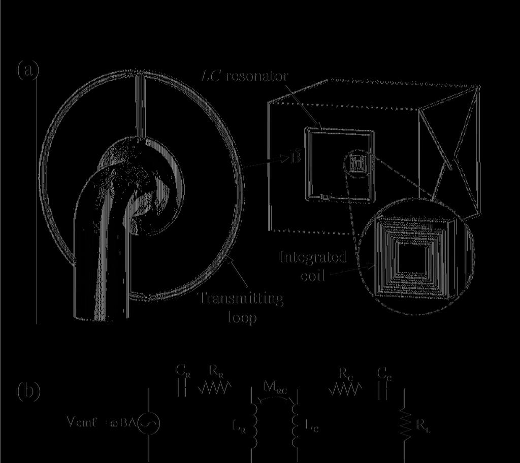
1 Wireless powering of single-chip systems with integrated coil and external wire-loop resonator. Fredy Segura-Quijano, Jesús García-Cantón, Jordi Sacristán, Teresa Osés, Antonio Baldi. Centro Nacional de Microelectrónica (IMB-CNM, CSIC), Esfera UAB, Campus UAB, Cerdanyola del Vallés, Barcelona, Spain. A procedure for inductive wireless powering of single-chip systems is presented. An integrated spiral coil is used as the power receiving component. An external resonator formed by a wireloop inductor connected to a capacitor is placed in close proximity to the chip. The sinusoidal magnetic field generated at a distant transmitting loop is amplified by the resonator. The present approach enables delivering power in the order of tens of microwatts to a few milliwatts at distances longer than 10 cm using a frequency of 13.5 MHz. The integrated coil used here can be fabricated with any integrated circuit fabrication technology. 1
2 Inductive wireless power transfer was demonstrated in the 19th century. Yet, contributions to the field are still appearing in the literature, which show potential for room size range wireless powering, 1 or sheet-type powering systems fabricated with low cost printing technologies. 2 The efficiency of inductive power transfer is not very high when the distance is larger than the size of the transmitting coil. However, since it provides a means for power supply without need of power cords or batteries, this technique is finding widespread application in small low power electronic devices such us access cards, radiofrequency identification tags, and wireless sensors. The general trend is to integrate as many possible components of the systems into a single chip. Typically for this integrated solutions, the chip is connected to an external coil through which the power is received. There are a number of reasons for trying to integrate also the coil and produce monolithically integrated systems. Low cost applications could benefit from this integration since most of the cost of current devices is associated with the process of connecting the chip to the external coil. 3 eliability could also be improved, especially for systems working in a wet environment. 4 However, integration of the receiving coil implies a decrease of coil area and quality factor that severely limits the maximum working distance of the wireless systems. Fully integrated systems proposed so far are designed for distances ranging from 1 to 3 mm. 5,6 In this letter we propose a procedure for wireless powering of single-chip systems that combine the cost and reliability advantages of fully integrated systems with the longer working range of external coil systems. Figures 1.a and 1.b show a schematic representation of the proposed system and its equivalent circuit, respectively. The chip is attached to a holder piece that contains a single loop inductor-capacitor (LC) resonator, but it is not connected to it. A distant transmitting loop generates a varying magnetic field that produces an electromotive force (V emf ) at the resonator loop. The current trough the loop is amplified by the resonance and generates a much 2
3 larger magnetic field than the original one. This wireless power transfer approach is similar to the one proposed by André Kurs et al. 1 for larger dimension devices. They achieve high power transfer efficiency by working in the strong coupling regime, that is, by ensuring that k 2 Q T Q > 1 where k is the coupling coefficient between the transmitting loop and the resonator, and Q T and Q are the quality factors of the transmitting loop and resonator, respectively. In the application presented here quality factors and coupling coefficient are much lower due to smaller dimensions of the resonant elements. This prevents working in the strong coupling regime. Nevertheless, the use of a resonant element close to the monolithically integrated system greatly increases the voltage and power picked up by the on-chip coil. The integrated coil used in this work was an aluminum 20 turn square spiral inductor with 3.5 mm side for the outer turn and 2.5 mm side for the inner turn. The fabrication was carried out by common photolithography and etching techniques on a 0.7 Ω cm p-type silicon wafer with a 2.0 µm-thick thermally grown silicon oxide layer and a 3 µm-thick aluminum layer deposited by sputtering. The inductance and series resistance measured at 13.5 MHz were 1.8µH and 220 Ω, respectively, which yields a quality factor of 0.7. The selfresonant frequency was 34.2 MHz, much larger than the target operation frequency (13.5 MHz). An integrated coil with similar parameters could be fabricated using any of the current commercial CMOS (Complementary Metal-Oxide-Semiconductor) technologies. The coil chip was glued and wirebonded to a printed circuit board with minimal dimensions to avoid additional magnetic coupling to its copper tracks. Three square loop resonators with side lengths of 1.25 cm, 2.5 cm and 5.0 cm where tested. The resonators where made with 1 mm-diameter cooper wire connected to chip capacitors (Murata GM40 series) whose values where chosen to yield 13.5 MHz resonant frequency. The power transmitting loop was 10 cm in diameter and was formed with 1 mm copper wire. The 3
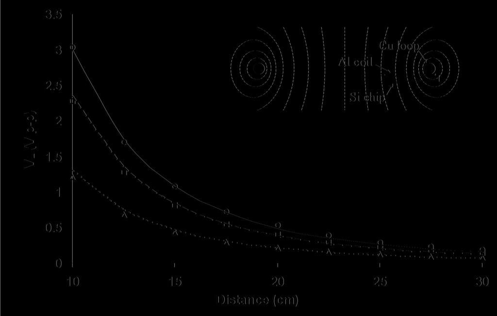
4 transmitting loop was also made to resonate at 13.5 MHz by connecting a tuning capacitor in parallel. A function generator (Agilent 33250A) with a smaller loop coupled to the transmitting loop was used to drive it in resonance. The sinusoidal voltage at the transmitting loop was measured to be 17.5 V amplitude throughout the experiments. This translates into a 0.7 A amplitude current for a reactive loop impedance of 25 Ω at 13.5 MHz. The voltage across the integrated coil was measured with a Yokogawa DL 9140L oscilloscope and 10x probes (16 pf and 1MΩ input impedance). Direct coupling from the transmitting loop to the oscilloscope probe and connection wires was measured to contribute less than 10 mv. Figure 2 shows results of the voltage obtained for the 2.5 cm side resonator with two different load resistances that emulate two system power consumptions. A curve for the case of no load is also shown. In order to maximize the coupling, and hence the transmitted power, the integrated coil was placed underneath the resonator wire as shown in Figure 2 inset. Power delivered to the 220 Ω load resistors for the three resonator sizes is shown in Figure 3. The power values where calculated from the measured voltages at the load resistor. Theoretical values of voltage and power at the load resistor are also shown in Figures 2 and 3. Calculations of the voltage amplitude measured at the load resistor were carried out using the equation V 2 2 = 0 C L (1) ω M 2 2 ( + ) + ω M C L B l 0 C derived from the equivalent circuit in Fig. 1.b, where ω 0 is the radian resonant frequency, l is the side length of the square shaped resonator, B is the magnetic field amplitude, M C is the mutual inductance between resonator and integrated coil, is the series resistance of the resonator, C is 4
5 the series resistance of the on-chip coil, and L is the resistance of the load. Here we assume that a capacitance C C is placed in series with the on-chip coil to cancel out its reactive part and maximize the received power. The analytical solution for the magnetic field, B, along the axis of a circular current loop is well known 7. We have not tried to obtain an analytical expression for because the contribution to the resonator losses come not only from the copper wire, but from the chip capacitors and the solder paste. Instead, the values used in the calculations were obtained from the resonators quality factor with the formula = ωl Q. The resonators quality factor was measured with the Agilent 4395A network analyzer, yielding 116.4, 106.4, and 87.5 for the 5 cm, 2.5 cm, and 1.25 cm side lengths, respectively. The mutual inductance, M C, was calculated using the method by Grover, 8 which is based on the exact solution for the mutual inductance of two parallel conductors. The results shown on Figure 3 demonstrates that the present power transfer approach enables delivering power in the order of tens of microwatts to a few milliwatts at distances longer than 10 cm to a fully integrated system coupled to (but no connected to) an LC resonator having dimensions smaller than a typical credit card. The theoretical values calculated with Equation 1 show a good match with the experimental results. The geometry of the elements used in this work was kept simple to allow an easy proof of concept and analytical description. The received power can be further increased by, for example, increasing the mutual inductance between the chip and the resonator loop, or by increasing the quality factor of the LC resonator. It is important to note also that the electromagnetic fields generated by the transmitting loop are below the limits fixed by the Institute of Electrical and Electronics Engineers (IEEE) regarding safety levels, 9 or the Federal Communications Commission (FCC) regarding electromagnetic compatibility. 10 5
6 1 A. Kurs, A. Karalis,. Moffatt, J.D. Joannopoulos, P. Fisher, M. Soljacic, Science 317, 83 (2007). 2 T. Sekitani, M. Takamiya, Y Noguchi, S. Nakano, Y. Kato, T. Sakurai, T. Someya1, Nat. Mater. 6, 413 (2007). 3 S.Y.L. Lim, S.C. Chong, L. Guo, W.Y. Hnin, Proceedings of 8th Electronics Packaging Technology Conference (IEEE Components, Packaging & Manufacturing Technology Society, Singapore, 2006), pp B. Ziaie, M.D. Nardin, A.. Coghlan, K. Najafi, IEEE Trans. Biomed. Engin. 44, 909 (1997). 5 T.S. Aytur, T. Ishikawa, B.E. Boser, 2004 Symposium on VLSI Circuits Digest of Technical Papers (IEEE Solid-State Circuits Society, Honolulu, HI, 2004), pp C. Neagu, H. Jansen, A.S.J. Gardeniers and M. Elwenspoek, Sens. Act. A 62, 599 (1997). 7 I.S. Grant, W.. Phillips, Electromagnetism (John Wiley and Sons, Chichester, England, 1990). 8 Grover, F.W., Inductance Calculations (Dover Pulications, New York, NY, 2004). 9 IEEE C , IEEE Standard for Safety Levels with espect to Human Exposure to adio Frequency Electromagnetic Fields, 3 khz to 300 GHz. 10 CF 47, Telecommunication, Chapter l-federal Communications Commission, Part , October 1,
7 Fig. 1: Inductive chip powering system: (a) schematic representation, (b) equivalent circuit of the resonator and integrated coil. Fig. 2: Voltage at the load resistor versus distance with the 2.5 cm side resonator for resistive loads of 220 Ω (triangles), 1kΩ (circles), and no load (squares). Calculated values are shown as doted, dashed and continuous traces, correspondingly. Inset shows the position of the chip relative to the cooper wire loop. Fig. 3: Power dissipated at the load versus distance for resonators with side length of 1.25 cm (triangles), 2.5 cm (circles), and 5 cm (squares). Calculated values are shown as doted, dashed, and continuous traces, correspondingly. 7
8
9
10
Maximum Power Transfer versus Efficiency in Mid-Range Wireless Power Transfer Systems
 97 Maximum Power Transfer versus Efficiency in Mid-Range Wireless Power Transfer Systems Paulo J. Abatti, Sérgio F. Pichorim, and Caio M. de Miranda Graduate School of Electrical Engineering and Applied
Electromagnetic Interference Shielding Effects in Wireless Power Transfer using Magnetic Resonance Coupling for Board-to-Board Level Interconnection
 Electromagnetic Interference Shielding Effects in Wireless Power Transfer using Magnetic Resonance Coupling for Board-to-Board Level Interconnection Sukjin Kim 1, Hongseok Kim, Jonghoon J. Kim, Bumhee
Study of Resonance-Based Wireless Electric Vehicle Charging System in Close Proximity to Metallic Objects
 Progress In Electromagnetics Research M, Vol. 37, 183 189, 14 Study of Resonance-Based Wireless Electric Vehicle Charging System in Close Proximity to Metallic Objects Durga P. Kar 1, *, Praveen P. Nayak
Optimization of Wireless Power Transmission through Resonant Coupling
 426 29 COMPATIBILITY AND POWER ELECTRONICS CPE29 6TH INTERNATIONAL CONFERENCE-WORKSHOP Optimization of Wireless Power Transmission through Resonant Coupling Yong-Hae Kim, Seung-Youl Kang, Myung-Lae Lee,
INVENTION DISCLOSURE- ELECTRONICS SUBJECT MATTER IMPEDANCE MATCHING ANTENNA-INTEGRATED HIGH-EFFICIENCY ENERGY HARVESTING CIRCUIT
 INVENTION DISCLOSURE- ELECTRONICS SUBJECT MATTER IMPEDANCE MATCHING ANTENNA-INTEGRATED HIGH-EFFICIENCY ENERGY HARVESTING CIRCUIT ABSTRACT: This paper describes the design of a high-efficiency energy harvesting
Chapter 2. Inductor Design for RFIC Applications
 Chapter 2 Inductor Design for RFIC Applications 2.1 Introduction A current carrying conductor generates magnetic field and a changing current generates changing magnetic field. According to Faraday s laws
A large-area wireless power transmission sheet using printed organic. transistors and plastic MEMS switches
 Supplementary Information A large-area wireless power transmission sheet using printed organic transistors and plastic MEMS switches Tsuyoshi Sekitani 1, Makoto Takamiya 2, Yoshiaki Noguchi 1, Shintaro
A Novel Dual-Band Scheme for Magnetic Resonant Wireless Power Transfer
 Progress In Electromagnetics Research Letters, Vol. 80, 53 59, 2018 A Novel Dual-Band Scheme for Magnetic Resonant Wireless Power Transfer Keke Ding 1, 2, *, Ying Yu 1, 2, and Hong Lin 1, 2 Abstract In
PIERS 2013 Stockholm. Progress In Electromagnetics Research Symposium. Proceedings
 PIERS 2013 Stockholm Progress In Electromagnetics Research Symposium Proceedings August 12 15, 2013 Stockholm, SWEDEN www.emacademy.org www.piers.org PIERS 2013 Stockholm Proceedings Copyright 2013 The
2. Measurement Setup. 3. Measurement Results
 THE INSTITUTE OF ELECTRONICS, INFORMATION AND COMMUNICATION ENGINEERS Characteristic Analysis on Double Side Spiral Resonator s Thickness Effect on Transmission Efficiency for Wireless Power Transmission
Accurate Models for Spiral Resonators
 MITSUBISHI ELECTRIC RESEARCH LABORATORIES http://www.merl.com Accurate Models for Spiral Resonators Ellstein, D.; Wang, B.; Teo, K.H. TR1-89 October 1 Abstract Analytically-based circuit models for two
SP 22.3: A 12mW Wide Dynamic Range CMOS Front-End for a Portable GPS Receiver
 SP 22.3: A 12mW Wide Dynamic Range CMOS Front-End for a Portable GPS Receiver Arvin R. Shahani, Derek K. Shaeffer, Thomas H. Lee Stanford University, Stanford, CA At submicron channel lengths, CMOS is
Investigation of a Voltage Probe in Microstrip Technology
 Investigation of a Voltage Probe in Microstrip Technology (Specifically in 7-tesla MRI System) By : Mona ParsaMoghadam Supervisor : Prof. Dr. Ing- Klaus Solbach April 2015 Introduction - Thesis work scope
Wireless Signal Feeding for a Flying Object with Strongly Coupled Magnetic Resonance
 Wireless Signal Feeding for a Flying Object with Strongly Coupled Magnetic Resonance Mr.Kishor P. Jadhav 1, Mr.Santosh G. Bari 2, Mr.Vishal P. Jagtap 3 Abstrat- Wireless power feeding was examined with
Flexibility of Contactless Power Transfer using Magnetic Resonance
 Flexibility of Contactless Power Transfer using Magnetic Resonance Coupling to Air Gap and Misalignment for EV Takehiro Imura, Toshiyuki Uchida and Yoichi Hori Department of Electrical Engineering, the
AN2972 Application note
 Application note How to design an antenna for dynamic NFC tags Introduction The dynamic NFC (near field communication) tag devices manufactured by ST feature an EEPROM that can be accessed either through
Time-Domain Analysis of Wireless Power Transfer System Behavior Based on Coupled-Mode Theory
 JOURNAL OF ELECTROMAGNETIC ENGINEERING AND SCIENCE, VOL. 6, NO. 4, 9~4, OCT. 06 http://dx.doi.org/0.555/jkiees.06.6.4.9 ISSN 34-8395 (Online) ISSN 34-8409 (Print) Time-Domain Analysis of Wireless Power
Watt-Level Wireless Power Transfer Based on Stacked Flex Circuit Technology
 Watt-Level Wireless Power Transfer Based on Stacked Flex Circuit Technology Xuehong Yu, Florian Herrault, Chang-Hyeon Ji, Seong-Hyok Kim, Mark G. Allen Gianpaolo Lisi*, Luu Nguyen*, and David I. Anderson*
Keywords Wireless power transfer, Magnetic resonance, Electric vehicle, Parameter estimation, Secondary-side control
 Efficiency Maximization of Wireless Power Transfer Based on Simultaneous Estimation of Primary Voltage and Mutual Inductance Using Secondary-Side Information Katsuhiro Hata, Takehiro Imura, and Yoichi
Exercise 1: Series Resonant Circuits
 Series Resonance AC 2 Fundamentals Exercise 1: Series Resonant Circuits EXERCISE OBJECTIVE When you have completed this exercise, you will be able to compute the resonant frequency, total current, and
THEORETICAL ANALYSIS OF RESONANT WIRELESS POWER TRANSMISSION LINKS COMPOSED OF ELEC- TRICALLY SMALL LOOPS
 Progress In Electromagnetics Research, Vol. 143, 485 501, 2013 THEORETICAL ANALYSIS OF RESONANT WIRELESS POWER TRANSMISSION LINKS COMPOSED OF ELEC- TRICALLY SMALL LOOPS Alexandre Robichaud *, Martin Boudreault,
Radio Frequency Electronics
 Radio Frequency Electronics Preliminaries II Guglielmo Giovanni Maria Marconi Thought off by many people as the inventor of radio Pioneer in long-distance radio communications Shared Nobel Prize in 1909
IN RECENT years, resonant wireless power transfer (WPT)
") IEEE TRANSACTIONS ON CIRCUITS AND SYSTEMS II: EXPRESS BRIEFS, VOL. 64, NO. 6, JUNE 2017 615 A Self-Resonant Two-Coil Wireless Power Transfer System Using Open Bifilar Coils Caio M. de Miranda and Sérgio
IEEE TRANSACTIONS ON CIRCUITS AND SYSTEMS II: EXPRESS BRIEFS, VOL. 64, NO. 6, JUNE 2017 615 A Self-Resonant Two-Coil Wireless Power Transfer System Using Open Bifilar Coils Caio M. de Miranda and Sérgio
Electromagnetic Field Exposure Feature of a High Resonant Wireless Power Transfer System in Each Mode
 , pp.158-162 http://dx.doi.org/10.14257/astl.2015.116.32 Electromagnetic Field Exposure Feature of a High Resonant Wireless Power Transfer System in Each Mode SangWook Park 1, ByeongWoo Kim 2, BeomJin
Wireless Power Transfer System via Magnetic Resonant Coupling at Fixed Resonance Frequency Power Transfer System Based on Impedance Matching
 EVS-5 Shenzhen, China, Nov. 5-9, Wireless Power Transfer System via Magnetic Resonant Coupling at Fixed Resonance Frequency Power Transfer System Based on Impedance Matching TeckChuan Beh, Masaki Kato,
AP Physics C. Alternating Current. Chapter Problems. Sources of Alternating EMF
 AP Physics C Alternating Current Chapter Problems Sources of Alternating EMF 1. A 10 cm diameter loop of wire is oriented perpendicular to a 2.5 T magnetic field. What is the magnetic flux through the
FEM SIMULATION FOR DESIGN AND EVALUATION OF AN EDDY CURRENT MICROSENSOR
 FEM SIMULATION FOR DESIGN AND EVALUATION OF AN EDDY CURRENT MICROSENSOR Heri Iswahjudi and Hans H. Gatzen Institute for Microtechnology Hanover University Callinstrasse 30A, 30167 Hanover Germany E-mail:
AC Circuits INTRODUCTION DISCUSSION OF PRINCIPLES. Resistance in an AC Circuit
 AC Circuits INTRODUCTION The study of alternating current 1 (AC) in physics is very important as it has practical applications in our daily lives. As the name implies, the current and voltage change directions
Simulation and design of an integrated planar inductor using fabrication technology
 Simulation and design of an integrated planar inductor using fabrication technology SABRIJE OSMANAJ Faculty of Electrical and Computer Engineering, University of Prishtina, Street Sunny Hill, nn, 10000
Study of Inductive and Capacitive Reactance and RLC Resonance
 Objective Study of Inductive and Capacitive Reactance and RLC Resonance To understand how the reactance of inductors and capacitors change with frequency, and how the two can cancel each other to leave
Mid-range Wireless Energy Transfer Using Inductive Resonance for Wireless Sensors
 Mid-range Wireless Energy Transfer Using Inductive Resonance for Wireless Sensors Shahrzad Jalali Mazlouman, Alireza Mahanfar, Bozena Kaminska, Simon Fraser University {sja53, nima_mahanfar, kaminska}@sfu.ca
By Hiroo Sekiya, Chiba University, Chiba, Japan and Marian K. Kazimierzuk, Wright State University, Dayton, OH
 ISSUE: November 2011 Core Geometry Coefficient For Resonant Inductors* By Hiroo Sekiya, Chiba University, Chiba, Japan and Marian K. Kazimierzuk, Wright State University, Dayton, OH A resonant inductor
California State University, Northridge Department of Electrical & Computer Engineering. Senior Design Final Project Report.
 California State University, Northridge Department of Electrical & Computer Engineering Senior Design Final Project Report FM Transmitter Josh Rothe Jonathan Rodriguez Pattrawut Phochana Jamell Jordan
Design of Integrated LC Filter Using Multilayer Flexible Ferrite Sheets S. Coulibaly 1, G. Loum 1, K.A. Diby 2
 IOSR Journal of Electrical and Electronics Engineering (IOSR-JEEE) e-issn: 2278-1676,p-ISSN: 232-3331, Volume 1, Issue 6 Ver. I (Nov Dec. 215), PP 35-43 www.iosrjournals.org Design of Integrated LC Filter
Analysis of RWPT Relays for Intermediate-Range Simultaneous Wireless Information and Power Transfer System
 Progress In Electromagnetics Research Letters, Vol. 57, 111 116, 2015 Analysis of RWPT Relays for Intermediate-Range Simultaneous Wireless Information and Power Transfer System Keke Ding 1, 2, *, Ying
Fabrication and application of a wireless inductance-capacitance coupling microsensor with electroplated high permeability material NiFe
 Journal of Physics: Conference Series Fabrication and application of a wireless inductance-capacitance coupling microsensor with electroplated high permeability material NiFe To cite this article: Y H
FEM Analysis of a PCB Integrated Resonant Wireless Power Transfer
 FEM Analysis of a PCB Integrated Resonant Wireless Power Transfer Žarko Martinović Danieli Systec d.o.o./vinež 601, Labin, Croatia e-mail: zmartinovic@systec.danieli.com Roman Malarić Faculty of Electrical
ELECTROMAGNETIC INDUCTION AND ALTERNATING CURRENT (Assignment)
") ELECTROMAGNETIC INDUCTION AND ALTERNATING CURRENT (Assignment) 1. In an A.C. circuit A ; the current leads the voltage by 30 0 and in circuit B, the current lags behind the voltage by 30 0. What is the
ELECTROMAGNETIC INDUCTION AND ALTERNATING CURRENT (Assignment) 1. In an A.C. circuit A ; the current leads the voltage by 30 0 and in circuit B, the current lags behind the voltage by 30 0. What is the
Självständigt arbete på avancerad nivå
 Självständigt arbete på avancerad nivå Independent degree project - second cycle Elektronik 30 hp Electronics 30 credits Titel Self-Tuning NFC Circuits Yimeng Li Self-Tuning NFC Circuits MID SWEDEN UNIVERSITY
IEEE TRANSACTIONS ON ANTENNAS AND PROPAGATION, VOL. 58, NO. 5, MAY X/$ IEEE
 IEEE TRANSACTIONS ON ANTENNAS AND PROPAGATION, VOL. 58, NO. 5, MAY 2010 1751 Numerical Analysis on Transmission Efficiency of Evanescent Resonant Coupling Wireless Power Transfer System Qiaowei Yuan, Qiang
University of Pennsylvania Moore School of Electrical Engineering ESE319 Electronic Circuits - Modeling and Measurement Techniques
 University of Pennsylvania Moore School of Electrical Engineering ESE319 Electronic Circuits - Modeling and Measurement Techniques 1. Introduction. Students are often frustrated in their attempts to execute
Wireless Communication
 Equipment and Instruments Wireless Communication An oscilloscope, a signal generator, an LCR-meter, electronic components (see the table below), a container for components, and a Scotch tape. Component
Radio Frequency Electronics
 Radio Frequency Electronics Frederick Emmons Terman Transformers Masters degree from Stanford and Ph.D. from MIT Later a professor at Stanford His students include William Hewlett and David Packard Wrote
PHYSICS WORKSHEET CLASS : XII. Topic: Alternating current
 PHYSICS WORKSHEET CLASS : XII Topic: Alternating current 1. What is mean by root mean square value of alternating current? 2. Distinguish between the terms effective value and peak value of an alternating
Equivalent Circuits for Repeater Antennas Used in Wireless Power Transfer via Magnetic Resonance Coupling
 Electrical Engineering in Japan, Vol. 183, No. 1, 2013 Translated from Denki Gakkai Ronbunshi, Vol. 131-D, No. 12, December 2011, pp. 1373 1382 Equivalent Circuits for Repeater Antennas Used in Wireless
Equivalent Circuit Model Overview of Chip Spiral Inductors
 Equivalent Circuit Model Overview of Chip Spiral Inductors The applications of the chip Spiral Inductors have been widely used in telecommunication products as wireless LAN cards, Mobile Phone and so on.
OPTIMIZED FRACTAL INDUCTOR FOR RF APPLICATIONS
 OPTIMIZED FRACTAL INDUCTOR FOR RF APPLICATIONS B. V. N. S. M. Nagesh Deevi and N. Bheema Rao 1 Department of Electronics and Communication Engineering, NIT-Warangal, India 2 Department of Electronics and
Coupling Coefficients Estimation of Wireless Power Transfer System via Magnetic Resonance Coupling using Information from Either Side of the System
 Coupling Coefficients Estimation of Wireless Power Transfer System via Magnetic Resonance Coupling using Information from Either Side of the System Vissuta Jiwariyavej#, Takehiro Imura*, and Yoichi Hori*
From Power to Performance in MHz Contactless Credit Card Technology
 From Power to Performance in.6 MHz Contactless Credit Card Technology M. Gebhart*, W. Eber*, W. Winkler**, D. Kovac**, H. Krepelka* *NXP Semiconductors Austria GmbH Styria, Gratkorn, Austria **Graz University
TECHNICAL REPORT: CVEL Parasitic Inductance Cancellation for Filtering to Chassis Ground Using Surface Mount Capacitors
 TECHNICAL REPORT: CVEL-14-059 Parasitic Inductance Cancellation for Filtering to Chassis Ground Using Surface Mount Capacitors Andrew J. McDowell and Dr. Todd H. Hubing Clemson University April 30, 2014
LEP RLC Circuit
 RLC Circuit LEP Related topics Kirchhoff s laws, series and parallel tuned circuit, resistance, capacitance, inductance, phase displacement, Q-factor, band-width, loss resistance, damping Principle The
BEST BMET CBET STUDY GUIDE MODULE ONE
 BEST BMET CBET STUDY GUIDE MODULE ONE 1 OCTOBER, 2008 1. The phase relation for pure capacitance is a. current leads voltage by 90 degrees b. current leads voltage by 180 degrees c. current lags voltage
i. At the start-up of oscillation there is an excess negative resistance (-R)
") OSCILLATORS Andrew Dearn * Introduction The designers of monolithic or integrated oscillators usually have the available process dictated to them by overall system requirements such as frequency of operation
OSCILLATORS Andrew Dearn * Introduction The designers of monolithic or integrated oscillators usually have the available process dictated to them by overall system requirements such as frequency of operation
PHASES IN A SERIES LRC CIRCUIT
 PHASES IN A SERIES LRC CIRCUIT Introduction: In this lab, we will use a computer interface to analyze a series circuit consisting of an inductor (L), a resistor (R), a capacitor (C), and an AC power supply.
Design and Characterization of a Power Transfer Inductive Link for Wireless Sensor Network Nodes
 Design and Characterization of a Power Transfer Inductive ink for Wireless Sensor Network Nodes R. W. Porto,. J. Brusamarello, I. Müller Electrical Engineering Department Universidade Federal do Rio Grande
Design of Duplexers for Microwave Communication Systems Using Open-loop Square Microstrip Resonators
 International Journal of Electromagnetics and Applications 2016, 6(1): 7-12 DOI: 10.5923/j.ijea.20160601.02 Design of Duplexers for Microwave Communication Charles U. Ndujiuba 1,*, Samuel N. John 1, Taofeek
Chapter Moving Charges and Magnetism
 100 Chapter Moving Charges and Magnetism 1. The power factor of an AC circuit having resistance (R) and inductance (L) connected in series and an angular velocity ω is [2013] 2. [2002] zero RvB vbl/r vbl
CHAPTER 5 Test B Lsn 5-6 to 5-8 TEST REVIEW
 IB PHYSICS Name: Period: Date: DEVIL PHYSICS BADDEST CLASS ON CAMPUS CHAPTER 5 Test B Lsn 5-6 to 5-8 TEST REVIEW 1. This question is about electric circuits. (a) (b) Define (i) (ii) electromotive force
Lab 1. Resonance and Wireless Energy Transfer Physics Enhancement Programme Department of Physics, Hong Kong Baptist University
 Lab 1. Resonance and Wireless Energy Transfer Physics Enhancement Programme Department of Physics, Hong Kong Baptist University 1. OBJECTIVES Introduction to the concept of resonance Observing resonance
Internal Model of X2Y Chip Technology
 Internal Model of X2Y Chip Technology Summary At high frequencies, traditional discrete components are significantly limited in performance by their parasitics, which are inherent in the design. For example,
Wireless Power Transmission for Autonomous Sensors in Removable Vehicle Seats
 Wireless ower Transmission for Autonomous Sensors in emovable Vehicle Seats Joan Albesa and Manel Gasulla Department of Electronic Engineering, ISI Group Universitat olitècnica de Catalunya (UC) Barcelona,
WIRELESS power transfer through coupled antennas
 3442 IEEE TRANSACTIONS ON ANTENNAS AND PROPAGATION, VOL. 58, NO. 11, NOVEMBER 2010 Fundamental Aspects of Near-Field Coupling Small Antennas for Wireless Power Transfer Jaechun Lee, Member, IEEE, and Sangwook
An induced emf is the negative of a changing magnetic field. Similarly, a self-induced emf would be found by
 This is a study guide for Exam 4. You are expected to understand and be able to answer mathematical questions on the following topics. Chapter 32 Self-Induction and Induction While a battery creates an
A Large Air Gap 3 kw Wireless Power Transfer System for Electric Vehicles
 A Large Air Gap 3 W Wireless Power Transfer System for Electric Vehicles Hiroya Taanashi*, Yuiya Sato*, Yasuyoshi Kaneo*, Shigeru Abe*, Tomio Yasuda** *Saitama University, Saitama, Japan ** Technova Inc.,
Optimized shield design for reduction of EMF from wireless power transfer systems
 This article has been accepted and published on J-STAGE in advance of copyediting. Content is final as presented. IEICE Electronics Express, Vol.*, No.*, 1 9 Optimized shield design for reduction of EMF
Exercises of resistors 1. Calculate the resistance of a 10 m long Copper wire with diameter d = 1.0 mm.
 Exercises of resistors 1. Calculate the resistance of a 10 m long Copper wire with diameter d = 1.0 mm. 2. Calculate the resistances of following equipment: using 220V AC a) a 1000 W electric heater b)
Improvement of 85 khz Self-resonant Open End Coil for Capacitor-less Wireless Power Transfer System
 216 Asian Wireless Power Transfer Workshop Improvement of 8 khz Self-resonant Open End Coil for Capacitor-less Wireless Power Transfer System Koichi FURUSATO, Takehiro IMURA, and Yoichi HORI The University
ET1210: Module 5 Inductance and Resonance
 Part 1 Inductors Theory: When current flows through a coil of wire, a magnetic field is created around the wire. This electromagnetic field accompanies any moving electric charge and is proportional to
Proceedings Contactless Interrogation System for Capacitive Sensors with Time-Gated Technique
 Proceedings Contactless Interrogation System for Capacitive Sensors with Time-Gated Technique Mehedi Masud *, Marco Baù, Marco Demori, Marco Ferrari and Vittorio Ferrari Department of Information Engineering,
An Equivalent Circuit Model for On-chip Inductors with Gradual Changed Structure
 An Equivalent Circuit Model for On-chip Inductors with Gradual Changed Structure Xi Li 1, Zheng Ren 2, Yanling Shi 1 1 East China Normal University Shanghai 200241 People s Republic of China 2 Shanghai
Pulse Transmission and Cable Properties ================================
 PHYS 4211 Fall 2005 Last edit: October 2, 2006 T.E. Coan Pulse Transmission and Cable Properties ================================ GOAL To understand how voltage and current pulses are transmitted along
International Journal of Scientific & Engineering Research, Volume 7, Issue 3, March-2016 ISSN
 ISSN 2229-5518 1102 Resonant Inductive Power Transfer for Wireless Sensor Network Nodes Rohith R, Dr. Susan R J Abstract This paper presents the experimental study of Wireless Power Transfer through resonant
Retuning Meshes in a Lower-Sideband-Ladder Crystal Filter
 Retuning Meshes in a Lower-Sideband-Ladder Crystal Filter Wes Hayward, w7zoi, 2September2018 The most common form of crystal filter we encounter in SSB/CW communications is the lower-sideband-ladder. An
Impedance Matching Techniques for Mixers and Detectors. Application Note 963
 Impedance Matching Techniques for Mixers and Detectors Application Note 963 Introduction The use of tables for designing impedance matching filters for real loads is well known [1]. Simple complex loads
EE301 ELECTRONIC CIRCUITS CHAPTER 2 : OSCILLATORS. Lecturer : Engr. Muhammad Muizz Bin Mohd Nawawi
 EE301 ELECTRONIC CIRCUITS CHAPTER 2 : OSCILLATORS Lecturer : Engr. Muhammad Muizz Bin Mohd Nawawi 2.1 INTRODUCTION An electronic circuit which is designed to generate a periodic waveform continuously at
Hybrid Impedance Matching Strategy for Wireless Charging System
 Hybrid Impedance Matching Strategy for Wireless Charging System Ting-En Lee Automotive Research and Testing Center Research and Development Division Changhua County, Taiwan(R.O.C) leetn@artc.org.tw Tzyy-Haw
AN2972 Application note
 Application note Designing an antenna for the M24LR64-R dual interface I²C/RFID device Introduction The M24LR64-R device is an EEPROM designed for access via two different interfaces: a wired I 2 C interface
Transcutaneous Energy Transmission Based Wireless Energy Transfer to Implantable Biomedical Devices
 Transcutaneous Energy Transmission Based Wireless Energy Transfer to Implantable Biomedical Devices Anand Garg, Lakshmi Sridevi B.Tech, Dept. of Electronics and Instrumentation Engineering, SRM University
Mechanism of Two Resonant Modes for Highly Resonant Wireless Power Transfer and Specific Absorption Rate
 Progress In Electromagnetics Research C, Vol. 69, 181 19, 216 Mechanism of Two Resonant Modes for Highly Resonant Wireless Power Transfer and Specific Absorption Rate Sangwook Park* Abstract In this work,
150Hz to 1MHz magnetic field coupling to a typical shielded cable above a ground plane configuration
 150Hz to 1MHz magnetic field coupling to a typical shielded cable above a ground plane configuration D. A. Weston Lowfreqcablecoupling.doc 7-9-2005 The data and information contained within this report
Christopher J. Barnwell ECE Department U. N. Carolina at Charlotte Charlotte, NC, 28223, USA
 Copyright 2008 IEEE. Published in IEEE SoutheastCon 2008, April 3-6, 2008, Huntsville, A. Personal use of this material is permitted. However, permission to reprint/republish this material for advertising
AC reactive circuit calculations
 AC reactive circuit calculations This worksheet and all related files are licensed under the Creative Commons Attribution License, version 1.0. To view a copy of this license, visit http://creativecommons.org/licenses/by/1.0/,
Bakiss Hiyana binti Abu Bakar JKE, POLISAS BHAB
 1 Bakiss Hiyana binti Abu Bakar JKE, POLISAS 1. Explain AC circuit concept and their analysis using AC circuit law. 2. Apply the knowledge of AC circuit in solving problem related to AC electrical circuit.
Streamlined Design of SiGe Based Power Amplifiers
 ROMANIAN JOURNAL OF INFORMATION SCIENCE AND TECHNOLOGY Volume 13, Number 1, 2010, 22 32 Streamlined Design of SiGe Based Power Amplifiers Mladen BOŽANIĆ1, Saurabh SINHA 1, Alexandru MÜLLER2 1 Department
Experimental Verification of Rectifiers with SiC/GaN for Wireless Power Transfer Using a Magnetic Resonance Coupling
 Experimental Verification of Rectifiers with Si/GaN for Wireless Power Transfer Using a Magnetic Resonance oupling Keisuke Kusaka Nagaoka University of Technology kusaka@stn.nagaokaut.ac.jp Jun-ichi Itoh
University of Pennsylvania Department of Electrical and Systems Engineering. ESE 206: Electrical Circuits and Systems II - Lab
 University of Pennsylvania Department of Electrical and Systems Engineering ESE 206: Electrical Circuits and Systems II - Lab AC POWER ANALYSIS AND DESIGN I. Purpose and Equipment: Provide experimental
Auxiliary Loop Antennas For AM Reception
 Auxiliary Loop Antennas For AM Reception Dipl.-Phys. Jochen Bauer 06/0/204 Abstract A common way of improving the reception of weak stations by an AM pocket radio with a relatively small build-in ferrite
Resonant wireless power transfer
 White Paper Resonant wireless power transfer Abstract Our mobile devices are becoming more and more wireless. While data transfer of mobile devices is already wireless, charging is typically still performed
Design Strategy of On-Chip Inductors for Highly Integrated RF Systems
 Design Strategy of On-Chip Inductors for Highly Integrated RF Systems C. Patrick Yue T-Span Systems Corporation 44 Encina Drive Palo Alto, CA 94301 (50) 470-51 patrick@tspan.com (Invited Paper) S. Simon
CHAPTER 6: ALTERNATING CURRENT
 CHAPTER 6: ALTERNATING CURRENT PSPM II 2005/2006 NO. 12(C) 12. (c) An ac generator with rms voltage 240 V is connected to a RC circuit. The rms current in the circuit is 1.5 A and leads the voltage by
Improvement of the Quality Factor of RF Integrated Inductors by Layout Optimization
 76 IEEE TRANSACTIONS ON MICROWAVE THEORY AND TECHNIQUES, VOL. 48, NO. 1, JANUARY 2000 Improvement of the Quality Factor of RF Integrated Inductors by Layout Optimization José M. López-Villegas, Member,
DUAL-BAND FILTER USING NON-BIANISOTROPIC SPLIT-RING RESONATORS
 Progress In Electromagnetics Research Letters, Vol. 13, 51 58, 21 DUAL-BAND FILTER USING NON-BIANISOTROPIC SPLIT-RING RESONATORS P. De Paco, O. Menéndez, and J. Marin Antenna and Microwave Systems (AMS)
Compact Distributed Phase Shifters at X-Band Using BST
 Integrated Ferroelectrics, 56: 1087 1095, 2003 Copyright C Taylor & Francis Inc. ISSN: 1058-4587 print/ 1607-8489 online DOI: 10.1080/10584580390259623 Compact Distributed Phase Shifters at X-Band Using
A 2.4 GHZ CMOS LNA INPUT MATCHING DESIGN USING RESISTIVE FEEDBACK TOPOLOGY IN 0.13µm TECHNOLOGY
 IJET: International Journal of esearch in Engineering and Technology eissn: 39-63 pissn: 3-7308 A.4 GHZ CMOS NA INPUT MATCHING DESIGN USING ESISTIVE FEEDBACK TOPOOGY IN 0.3µm TECHNOOGY M.amanaeddy, N.S
Understanding and Optimizing Electromagnetic Compatibility in Switchmode Power Supplies
 Understanding and Optimizing Electromagnetic Compatibility in Switchmode Power Supplies 1 Definitions EMI = Electro Magnetic Interference EMC = Electro Magnetic Compatibility (No EMI) Three Components
On-Chip Passive Devices Embedded in Wafer-Level Package
 On-Chip Passive Devices Embedded in Wafer-Level Package Kazuya Masu 1, Kenichi Okada 1, Kazuhisa Itoi 2, Masakazu Sato 2, Takuya Aizawa 2 and Tatsuya Ito 2 On-chip high-q spiral and solenoid inductors
Model of Contactless Power Transfer in Software ANSYS
 POSTE 06, PAGUE MAY 4 Model of Contactless Power Transfer in Software ANSYS adek Fajtl Dept of Electric Drives and Traction, Czech Technical University, Technická, 66 7 Praha, Czech epublic fajtlrad@felcvutcz
INF 5490 RF MEMS. LN12: RF MEMS inductors. Spring 2011, Oddvar Søråsen Department of informatics, UoO
 INF 5490 RF MEMS LN12: RF MEMS inductors Spring 2011, Oddvar Søråsen Department of informatics, UoO 1 Today s lecture What is an inductor? MEMS -implemented inductors Modeling Different types of RF MEMS
Design and Simulation of Voltage-Mode and Current-Mode Class-D Power Amplifiers for 2.4 GHz Applications
 Design and Simulation of Voltage-Mode and Current-Mode Class-D Power Amplifiers for 2.4 GHz Applications Armindo António Barão da Silva Pontes Abstract This paper presents the design and simulations of
Theory: The idea of this oscillator comes from the idea of positive feedback, which is described by Figure 6.1. Figure 6.1: Positive Feedback
 Name1 Name2 12/2/10 ESE 319 Lab 6: Colpitts Oscillator Introduction: This lab introduced the concept of feedback in combination with bipolar junction transistors. The goal of this lab was to first create