2001 by UPS Aviation Technologies, Inc. All rights reserved. Printed in the U.S.A.
|
|
|
- Linette West
- 5 years ago
- Views:
Transcription
1
2 No part of this document may be reproduced in any form or by any means without the express written consent of UPS Aviation Technologies, Inc. UPS Aviation Technologies, Inc., II Morrow, and Apollo are trademarks of UPS Aviation Technologies, Inc by UPS Aviation Technologies, Inc. All rights reserved. Printed in the U.S.A. UPS Aviation Technologies, Inc Turner Road S.E. Salem, OR U.S.A. Toll Free Canada Toll Free International FAX Visit our web page at Send comments about this manual by to:
3 History of Revisions Date Software Version Manual Revision January Capstone Release February GA Release April a August December July April April a June b Ordering Information To receive additional copies of the Apollo MX20 User s Guide, order part # b. The Apollo MX20 Installation Guide is part # xx. The MX20 Quick Reference Guide is part # xx. i
4 End User License Agreement ( EULA ) Refund. If you do not agree to the terms of this EULA, UPS Aviation Technologies and Microsoft are unwilling to license the MX20 and its Operating System to you. In such event, you may not use or copy the Licensed Product, and you should promptly contact UPS Aviation Technologies for instructions on return of the unused product(s) for a refund. Client Access Licenses. If you use the MX20 Operating System to access or utilize the services or functionality of Microsoft Windows NT Server (all editions) or use the MX20 Operating System to permit workstation or computing devices to access or utilize the services or functionality of Microsoft Windows NT Server, you may be required to obtain a Client Access License for the MX20 Operating System and/or each such workstation or computing device. No Warranties. Except as expressly provided in the limited warranty section, the MX20 and its operating system are provided to you as is without warranty of any kind, either expressed or implied, including, but not limited to, warranties of noninfringement, merchantability, and/or fitness for a particular purpose. the entire risk of the quality and performance of the software is with the user. No Liability for Consequential Damages. UPS Aviation Technologies and/or UPS Aviation Technologies software suppliers shall not be held liable for any damages suffered or incurred by you (including, but not limited to, general, special, consequential or incidental damages including damages for loss of business profits, business interruption, loss of business information and the like), arising from or in connection with the delivery, use, or performance of the software. Customer Remedies. UPS Aviation Technologies and UPS Aviation Technologies suppliers entire liability and your exclusive remedy shall be, at UPS Aviation Technologies option, either (a) return of the price paid, or (b) repair or replacement of the MX20 and its operating system that does not meet the above Limited Warranty and which is returned to UPS Aviation Technologies with a copy of your receipt. This Limited Warranty is void if failure of the MX20 or its operating system has resulted from accident, abuse, or misapplication. Any replacement MX20 and its operating system will be warranted for the remainder of the original warranty period or thirty (30) days, whichever is longer. Limitations on Reverse Engineering, Decompilation and Disassembly. You may not reverse engineer, decompile, or disassemble the MX20 or its operating system, except and only to the extent that such activity is expressly permitted by applicable law notwithstanding this limitation. Separation of Components. The MX20 and its operating system are licensed as a single product. Its component parts may not be separated for use on more than one MX20. Single Embedded System. The MX20 and its operating system are licensed with the MX20 as a single integrated product. The MX20 operating system may only be used with the MX20 as set forth in these licensing terms. ii
5 Welcome Welcome to a new era of aviation navigation. Once again, UPS Aviation Technologies, Inc. has set new standards in features and ease of use for the general aviation public. The Apollo MX20 Multi-Function Display provides a focal point for integrating many of your navigation needs in an easy to use and convenient package. The MX20 presents a wealth of information on its six-inch diagonal, 640x480 pixel, color display. The many features are organized as distinct functions and are designed to closely mimic the traditional instruments used in the standard cockpit. Each function allows varying degrees of customization. The custom map function is customizable so you can create a display for almost any configuration you require. The other functions provide more limited levels of customization so that they retain the look and feel of the instruments they reflect. The MX20 is capable of creating powerful overlay views where information from a variety of sources can be presented simultaneously in proper relationship to each other, thus greatly increasing situational awareness for the pilot. You can be confident in knowing that you are the owner of the state-of-the-art in aviation and navigation. The MX20 architecture is designed to support full expansion for both software and hardware enhancements. This flexibility protects your investment and allows for the ease of adding new features. Our products are built to last and to allow the flexibility to meet your needs as they change in the future. iii
6 About This Manual This manual may be used as a summary, a reference, and a learning tool. Information is provided about all of the functions available to the MX20. Your specific installation may not include all of these functions. Take a few moments to familiarize yourself with the various sections in this manual. The Getting Started section gives an introduction to the controls, basic operation, and organization of the functions in your MX20. Be sure to read the Getting Started section to learn the rules for using the MX20. The Detailed Operation section is the reference for each of the functions in the MX20. Refer to the Detailed Operation section when you want to get into the details on every function and option along with step-by-step instructions. Not every function is available in all software versions or in every installations. iv
7 Table of Contents History of Revisions...i Ordering Information...i Welcome... iii About This Manual...iv Getting Started Functions....1 Controls...3 Power/Brightness...3 Function ( FN)...3 Menu/Enter...4 Line Selection...4 DataCard...5 Display...6 Annunciations Advisory Flags....7 Data Flags Message Flag...9 Basic Operation...9 Power On Pre-Heat Mode...10 Brightness Start Up Screen...10 Confirm Current Baro Correction Function Selection Advisory Hot Key...12 Alert Hot Key...13 Options Menu...14 Detailed Operation Message Log (MSG) Function...18 Custom Map (MAP) Function...19 Map Scale Auto Zoom Pan...20 Info v
8 vi Info In Pan Mode...22 Initial Zoom Level Flight Plan Map Orientation...23 Invert...24 NavData Load Chart (Optional)...25 Airports...26 VORs...26 NDBs...29 Intersections...29 Airspace Low Airways...30 High Airways...31 Water...31 Roads...31 Boundary Airport Chart Terrain...33 Obstructions...33 Traffic...33 Strikes...34 IFR Chart Function...35 Flight Plan Map Orientation...35 Invert...36 NavData Label...37 Low Airways...37 High Airways...37 Airport Chart Load Chart VFR Chart Function...39 Flight Plan Map Orientation...39 Invert...40 NavData
9 Label...40 Skywatch / TCAD Traffic Function Traffic Depiction...41 Alert Hot Key...41 Symbology Custom Map Display...42 Vert Smart Key (Skywatch)...42 Traffic Status Indicators No Bearing Advisories Skywatch Menu Options...43 TCAD 9900B Menu Options...44 TCAD 9900BX Menu Options ADS-B Traffic Function...46 Traffic Description...46 Flight Plan Traffic Map Orientation...49 Display Mode...50 Altitude Option (Relative/Pressure) Time...51 ADS-B Broadcast Mode Control Flight ID Editing...52 Traffic Altitude Filter...53 Label...53 Services...53 Flight Plan (FPL) Function...54 Terrain (TER) Function Flight Plan TRK Up Arc/TRK Up Set Barometer...58 TER Data Flag Weather (WX) Data Link...59 Flight Information Service-Broadcast (FIS-B) Navigating the Displayed Data Smart Key Function...62 Sorting FIS Messages...63 Lightning Strikes (LT) Function...64 Flight Plan / vii
10 viii
11 Getting Started Getting Started This section explains how to get started using the MX20. Information in this section describes the controls, data card, display, and basic operation. After reading this section, go to the Detailed Operation section for expanded explanations for each feature. Functions The MX20 contains thirteen major separate functions for the display of information. The function names are shown as smart keys at the bottom of the display. The smart key is the combination of a label above a triangle key at the bottom of the display. The labels above the triangle keys change to reflect the choices available to you for each function. Press the FN key to show the available functions. Press the smart key below the function label to go to the displayed function. While in each function, press the MENU/ENTER key to show the options for each function. The options are shown on the right side of the display. Press the LINE SELECT key to manipulate the options. Some options toggle on/off, while some are tri-state (three choices). The functions are: MSG - Message Log (See page 18 for details) MAP - Custom Map (See page 19 for details) IFR - IFR Chart (See page 35 for details) VFR - VFR Chart (See page 39 for details) Skywatch/TCAD Traffic (See page 41 for details) ADS-B TRAF - Traffic (See page 46 for details) FPL - Flight Plan (See page 54 for details) TER - Terrain (See page 55 for details) WX - Weather Data Link (See page 59 for details) FIS-B - Flight Information Service - Broadcast (See page 61 for details) LT - Lightning Strikes (See page 64 for details) CHART - Chart View (See page 68 for details) 1
12 Getting Started RADAR - Weather Radar (See page 79 for details) SYS - System Information (See page 87 for details) The Message Log displays information from the MX20 or reported to the MX20 by its external sensors. A flashing MSG annunciator notifies you of a new message that should be viewed. The Custom Map function allows you to completely customize the displayed map by overlaying selected information. The Custom Map can become cluttered if you choose every option, so use discretion. The IFR Chart function provides an IFR en route style map on the display. The VFR Chart function provides a VFR sectional style map for the display. The Traffic function (when installed) shows nearby traffic and details about each target. The Flight Plan function provides details about your flight plan and each waypoint. The Terrain function shows a color coded map of terrain elevation in relation to your altitude. The Weather Data Link function is capable of displaying graphic weather information with UAT-equipped installations. The Flight Information Services function allows access to text weather data messages on UAT-equipped installations. The Lightning function, when connected to the Goodrich WX500 Stormscope, controls the overlay of lightning strike information on the map displays. The Chart View feature provides the capability to view Jeppesen Sanderson Inc. electronic charts. Two basic types of charts can be viewed: Approach charts and airport surface charts. The Radar Function allows weather radar from the ART2000 to be displayed. The System Information function lets you set general preferences, show software version information, and test the display. 2
13 Getting Started OFF Controls Power/Brightness The power switch is located in the upper right corner of the MX20. Turn the power rotary knob clockwise past the detent to turn the power on. Turn the power knob fully counterclockwise to turn the power off. With the power knob pushed in, the brightness is set automatically according to ambient light by a photo sensor. Pull the knob out and turn the knob to adjust the display brightness manually. Function ( FN) The Function keys are made up of one dedicated key on the lower left side of the display and the four smart keys to the right of it. Press the function (FN) key repeatedly to scroll through the available functions. The functions will appear above the smart function keys in turquoise. Function Key MSG MAP IFR VFR FN Smart Function Keys Smart Key Labels Use the FN key to display a list of the main functions, such as Map, IFR, Terrain, etc. Each time you press the FN key you will step through the list of functions. After you press one of the function smart keys at the bottom of the display, the function keys change to provide options to control the display related to the current function. Function Key In Out Pan Info FN Smart Function Option Keys Smart Key Labels Change the function keys back to the function list by pressing the FN key. 3
14 Getting Started MENU ENTER Menu/Enter The MENU/ENTER key is located on the bottom right corner of the MX20. Press the MENU/ENTER key to show a menu of options to modify the display of the current function. Press the MENU/ENTER key to hide the menu. If no action is taken, the menu will automatically extinguish in a few seconds. Line Selection The Line Selection keys are on the right side of the MX20. Press the MENU/ENTER key to see the options for the current function. Press the LINE SELECT key next to each option to scroll through the choices for each option. Some options support tri-state choices, such as in Map mode. When you select a tri-state option, the option label will change with each key press between completely filled, partially filled, and empty. Option Labels Option 1 Option 2 Option 3 Line Select Keys Option 4 Option 5 Option 6 MENU ENTER 4
15 Getting Started Data Card The Map database and other information is stored on a data card. The use of a data card allows you to easily update information. Only change the data card when the power is turned off. Handle your data card carefully. Do not touch the connector edge of the data card. To eject the card, use a soft blunt object to press the data card ejector. Gently pull the card straight out of the slot. Insert a data card by pushing the card straight into the slot. When fully inserted, the data card and eject button will be flush and slightly recessed into the bezel. Front View of Data Card Slot Data Card Data Card Ejector Side View ofdata Card Front When contacting your dealer or the UPS Aviation Technologies technical services staff, eject the data card and write down the information shown on the label. UPS Aviation Technologies APOLLO Mx20 ( xxx) TSO C113, TSO C110A DO-178B LEVELS C,D SW P/N SW Version NavData Part No. of Mx20 software Version of Mx20 software Nav Data: Copyright Jeppesen Sanderson, Inc UPS Aviation Technologies Inc. All Rights Reserved. Date of Jeppesen Nav data 5

16 Getting Started Display The MX20 display provides text and graphic information to give a picture of your flight and surroundings. The display brightness may be set manually or allowed to automatically adjust to ambient light conditions. At the bottom of the display, labels above the function keys change to show the different choices for each function to allow access to commonly used actions. A typical Custom Map function display is shown below. See page 94 for details on display care. TO Waypoint Identifier Graphic Display Traffic Obstruction Distance to Destination Wpt Bearing to Destination (TO) Wpt Traffic Thumbnail MFD A POLLO MX20 OFF Power/Dimming Ownship Advisory Flags Line Select Keys Data Flags Zoom (Map Scale) Message Flag Menu/Enter Key Function Key Photosensor MENU ENTER Data Card Ejector FN Smart Keys Smart Function Key Labels Mounting Screw Currently Selected Function Data Card The MX20 will go into a pre-heat mode for a short period of time on start-up. During the pre-heat mode, the display will remain dark. The pre-heat mode is designed to extend the life of the LCD backlight. 6
17 Getting Started Annunciations Advisory flags, data flags, and messages appear on the display to give information about the status of the MX20 or to provide operating information. TRAF TRAFFIC ALERT TER STRK Advisory Flags Annunciations will appear on the upper left side of the display to provide advisories for Traffic, Terrain, and Lightning. Advisory information is monitored and displayed regardless of the selected function. Advisory flags will flash for approximately 10 seconds when they first appear and then turn solid while they are still valid. Advisory icons will reduce in size if more than two advisory conditions exist. ADS-B Traffic The Traffic advisory flag will appear on the left side of the display when traffic is reported to be within ±2000 feet of your altitude and 5 nm of your location. The Traffic advisory and Traffic functions are only available when the ADS-B system is installed. Skywatch/TCAD Traffic The Traffic Advisory/Alert will appear in amber on the left side of the display when the traffic sensor indicates an alerting condition. Terrain The Terrain advisory flag will appear on the left side of the display when the terrain surface or obstacle altitude is within approximately 500 feet of your altitude and within approximately two minutes of flight in any direction. Lightning The Lightning advisory flag will show on the left side of the display when the WX500 sends an indication that lightning has been detected within 50 nm of your location. See the WX500 manual for details about range and other capabilities. 7
18 Getting Started Data Flags Data flags appear on the left side of the display to notify you when there is a loss of reported information. The data usually displayed, such as lightning or nearby terrain, may still exist, but may not be displayed for technical reasons. For instance, when the amber TRAF data flag appears it means that the MX20 is not receiving Traffic information from the sensor. So, traffic may exist in your vicinity, but will not be displayed on the MX20. POS RTE ALT TRAF LT TER NAV SKYW TCAD No valid position information is available from the source. Do not expect a valid position representation on the maps. The Ownship symbol will have an X through it. No valid route (flight plan) is available from the external navigation source. Route (flight plan) information will not be shown on the maps. No valid altitude information is available from the external source. Altitude related functions will not operate, such as terrain awareness. No traffic information is received from the external source. Traffic will not be displayed. Your position information will not be broadcast in ADS-B capable systems. No valid lightning detection information is being received from the external source. Strike and cell information will not be displayed. Terrain coverage is not available for some part of the terrain advisory coverage area. Terrain advisories may not be provided. When connected to the SL30, indicates the SL30 is not available or valid. ILS, OBS, and VORs will not be highlighted. No valid traffic information is being received from the Skywatch sensor. Traffic information will not be displayed. No valid traffic information is being received from the Ryan TCAD sensor. Traffic information will not be displayed. 8
19 Getting Started RDR (Amber) RDR (Green) RDR (Green - Flashing) Indicates that radar status information is not available from the external radar transmitter head. Radar related functionality may not be available. Indicates that the radar is ON and transmitting RF energy. Appropriate precautions should be taken. Indicates that the radar is in Hold and is transmitting RF energy. Appropriate precautions should be taken. Message Flag The Message flag will appear on the lower left side of the display when a new message is posted. Go to the Message function to view the information about the operation or status of the MX20. Basic Operation Use the following items to get a basic feel for the operation of the MX20. The basic steps for using any of the separate functions of the MX20 are: Turn the power on. Adjust the brightness or set it to automatic. Check that all tests pass on the Start Up screen. Press the FN key to view available functions. Each press of the FN key will step through the lists of functions. Press the key below the function label to select the desired function. Confirm or enter the current barometric pressure Press the MENU/ENTER key to display available options. Press the LINE SELECT key next to the displayed option to choose desired capabilities. Some options use multiple key presses for different states for the option. Press the MENU/ENTER key again to extinguish the option display. Refer to the Detailed Operation section for more details on each function. 9
20 Getting Started Power On Turn the power rotary knob clockwise past the detent to turn the power on. The MX20 will progress through a series of startup screens. The final startup screen shows System Information and the results of the Self-Test. Pre-Heat Mode The MX20 will go into a pre-heat mode for a short period of time on start-up. During the pre-heat mode, the display will remain dark. The pre-heat mode is designed to extend the life of the LCD backlight. Brightness With the Power knob pulled out, turn the knob in each direction to adjust the display brightness manually. Manual brightness mode may be selected to adjust the display for difficult lighting conditions. Push the knob in, and the brightness is adjusted automatically according to the ambient light. When the brightness is set automatically, the display will not dim below a pre-defined level. Start Up Screen The Start Up screen is displayed while the MX20 goes through its initialization and testing routines. System information is shown that provides the MX20 software and database versions. The results of the self test are shown. A check mark shows that the test passed. If any of the Self-Tests fail (red x ), contact your dealer or the factory (see page 94). 10


21 Getting Started Confirm Current Baro Correction A window will appear at startup, and then every 30 minutes, that displays the current barometric value. You must verify the current value or enter a new value. Press BARO + to increase the value. Press BARO - to decrease the value. Press OK to confirm the existing values or to accept changes you have just entered. Function Selection Press the FN key to view the different Functions. The functions are shown above the function smart keys on the lower part of the display in green. Press the function key under the function label to activate that function. The labels above the function key will change to reflect the custom smart controls for that function. All of the described functions may not be available in each installation. 11
22 Getting Started Function MSG MAP IFR VFR TRAF FPL TER WX FIS LT CHART RADAR SYS Description Message Log Function Custom Map Function IFR En Route Map VFR Sectional Map Traffic Display Flight Plan Information Terrain Depiction Graphical Weather Text Weather Lightning Detection and Reporting Chart View Weather Radar Function System Information Advisory Hot Key The Advisory Hot Key feature allows advisory conditions to be quickly viewed with minimal effort by the pilot. This feature is comprised of three components: 1) An advisory condition is indicated by a white advisory flag on the left side of the screen, the corresponding Function label will also be highlighted in white when selecting a new Function with the FN key. This feature allows any Function with a pending advisory to quickly be recognized in the Function menu. 2) When a function is entered that has an advisory posted, the zoom level will be adjusted to show the advisory causing object (terrain for example), and the map mode will be forced to Track Up 360 to get a good view of what is around the aircraft. 3) When returning to the previous Function after viewing a Function with an advisory, the original zoom and map mode will be restored. This feature is designed to allow the pilot to establish a preferred cruise map setup and quickly view an 12
23 Getting Started advisory, then return back to the previous setting. For example: Normal Cruise Condition Custom Map Function is being viewed at 5 nm in the ARC mode. Terrain Advisory Occurs at 10nm in front of aircraft: The Terrain Advisory Indicator flashes then goes steady on the left side of the display. Viewing the Advisory The pilot presses the FN key and sees the TER Function highlighted in white, indicating it has an advisory condition. Pressing the TER key to enter the Terrain Function at this point will automatically adjust the zoom level to 10nm and place the unit in full 360 mode to show overall situational awareness. Returning To Normal Condition After evaluating the advisory, to return to normal viewing simply select the original Function that was being viewed before the advisory was viewed. When this is done, the zoom level will be set back to 5 nm and the display mode will be returned to ARC mode. Alert Hot Key Traffic alerts go one step further than the Advisory hot key feature and will automatically bring up the Function Menu showing the Traffic function. A single key press can then be used to switch the display to the Traffic function. The Alert hot key feature will automatically clear when the traffic alert condition no longer exists. Also note that a pop-up mode can be enabled on the Traffic function, which makes the Traffic page pop-up when a Traffic Advisory occurs. June
24 Getting Started Options Menu Most functions have a number of options available. Press the MENU/ENTER key to see the options for the current function. You change an option by pressing one of the Line Selection keys that are to the right of the displayed option. Many options have more than one choice. Press the same LINE SELECT key repeatedly to select the available choices. Some functions have several pages of options. The lower LINE SELECT key will allow you to reach the Next Page when multiple pages are available. Press the MENU/ENTER key a second time to remove the menu from view or wait a few seconds for the options to automatically extinguish. 14
25 Getting Started Press Function Keys MSG MAP IFR VFR Press Line Selection Keys Flight Plan Map Orient Invert Nav Data Load Chart Airports VORs NDBs Intersections Airspace Low Airways High Airways Water Roads Boundary Airport Chart Terrain Obstructions Traffic Strikes Press Line Selection Keys Flight Plan Map Orient Invert Nav Data Label Low Airways High Airways Airport Chart Load Chart Press Line Selection Keys Flight Plan Map Orient Invert Nav Data Label Skywatch Press Line Selection Keys Alert Mode Standby Press Line Selection Keys TRAF Altitude Option Altitude Filter Volume Approach Mode Mute Duration Shield Shield Heights Shield Ranges Alert Mode (Optional by Installation) TCAD 9900B TCAD 9900BX ADS-B Traffic Press Line Selection Keys Altitude Option Altitude Filter Volume Approach Mode Gnd/Flt Mode Alert Mode Press Line Selection Keys Press Function Keys Flight Plan Map Orient Display Mode Altitude Time Broadcast FID Enter FID Altitude Filter Label Services FPL TER WX Press Line Selection Keys Flight Plan Map Orient Set Barometer Press Line Selection Keys Flight Plan Map Orient Invert Clear Press Function Keys FIS LT CHART RADAR SYS Press Line Selection Keys Flight Plan 360/120 Lightning Hdg Stab System Data Demo Self Test Noise Monitor Strike Test Press Line Selection Keys Search ID Select Airport Select Chart Select Loaded Load Current Press Line Selection Keys Mode Wx/Map Horiz/Vert Tilt/Brg Gain/Hold Nav Press Line Selection Keys Press Function Keys Info Ownship Symbol Lat/Lon Format Set Baro Correction Display Lat/Lon Lines Initial Enroute Zoom Scale Initial Ground Zoom Scale Enroute Ground Transition Speed Press Line Selection Keys Test Test Pattern 1 Red Test Pattern Green Test Pattern Blue Test Pattern White Test Pattern June
26 Getting Started Notes 16
27 Detailed Operation This section describes each operating function and the options available in each function. Each function operates independently. The Function smart keys and Line Selection keys are customized for each function and will appear while that function is selected. The functions are described in the order that they appear. A description of each function will be followed by an explanation of how the function smart keys operate for the function and then each menu option as selected by the Line Selection keys. All described functions may not be available in your particular installation. See your Airplane Flight Manual supplement for the details on your individual installation. 17

28 Message Log (MSG) Function The Message function displays information about the status of the MX20. Messages may be logged by either the MX20 internal system or by one of the external sensors. The amber MSG flag will flash until the message is viewed. The MSG flag will remain in view while any messages remain in the message log. New messages that have not been viewed will be highlighted as bold text. 1. Press FN until you see the MSG function key. 2. Press the MSG key. 3. Use the UP/DOWN arrow smart keys to move to additional messages, if more than one page of messages exist. 4. Press CLEAR to remove the stored messages. 18
29 Custom Map (MAP) Function The Custom Map function provides a graphic display of map features in relation to the aircraft location to help improve your situational awareness. The custom map function is unique in that it has the ability to selectively overlay all available types of information onto a single display. You can customize the map display by overlaying information selected from a menu of options. Press the MENU key to display a list of options on the right side of the screen. Press the LINE SELECT key next to the displayed option. Repeated presses of the LINE SELECT key will scroll through the available selections for each option. The smart keys at the bottom of the display over the function keys control the map scale by zooming in or out, moving the map view around with the Pan feature, and viewing Info about the current destination waypoint. Map Scale The In and Out function keys control the map scale by zooming in and out. You can zoom in to 0.25 nm and zoom out to 250 nm. The scale distance is measured from the location of your aircraft symbol to the top of the screen. The Map Scale is shown in the lower left corner of the screen. The map orientation appears above the map scale on one of the three Nav Data options. Zoom Level Map Orientation 19
30 Auto Zoom Auto Zoom is activated by adjusting the zoom level to the far extremes of the zoom range. When activated, the indicated zoom level will change from a number to the text AUTO. While in the Auto Zoom mode, the screen will automatically adjust the current zoom level to maintain the current TO waypoint on the screen. When approaching the waypoint, the zoom level will not drop below 1 nm. When the waypoint is reached and the next waypoint in the flight plan becomes active, the zoom level will automatically adjust to bring that waypoint on the map. To exit the autozoom mode, simply increase or decrease the current zoom level to re-enter the manual adjust mode. Pan The Pan keys are used to move the display around so you can see beyond the initial boundaries of the screen. The PAN function key is one of the smart keys available at the bottom of the screen. When you select the Pan function, four arrow keys appear on the right side of the screen next to the LINE SELECT keys. Move the map in the desired direction by pressing the LINE SELECT key next to the arrow that shows you want the map to move. Press the PAN key again to exit the Pan mode. While panning, a 20

31 green reference line is drawn from the center of the viewed area back to your current position. Info Press the INFO smart key to view information about the current TO waypoint. Each press of the INFO key will step through the available information for the current destination waypoint. The number of pages depends on the amount of information about the destination waypoint. Runway diagrams of airports will be displayed in the same orientation as the main map (i.e., North Up, Track Up, or DTK Up). 21
32 Info In Pan Mode The INFO smart key supports operation in conjunction with the PAN feature. On any of the maps (Custom Map, IFR and VFR), entering the INFO mode while pan is active, will show information about the nearest airport to the center of the screen. This allows panning around the immediate area and obtaining information about airports in the vicinity without changing the current TO waypoint. While in this mode, both the PAN and INFO smart keys are highlighted. Only information about airports can be obtained with this feature. Initial Zoom Level The initial zoom level that is used on start-up is determined by a setting made in the System Function (see page 88). 22

33 Custom Map Menu Option Page 1 The first option page of the Custom Map function lets you select options for the choices of Flight Plan, map orientation, Invert, Nav Data, and Load Chart. The last option selection takes you to the next page of options. The options have tri-state choices that are also shown visually. When the option is clear, the icons and labels are not displayed. When the option is solid, icons and labels are all shown. When the option box is partially filled, only the icons are shown. Flight Plan The Flight Plan option controls the display of the Flight Plan course line. Pressing the LINE SELECT key next to the Flight Plan option toggles between showing or not showing the Flight Plan route line. Map Orientation This option controls the screen orientation in reference to the aircraft symbol. You may select from North Up, Track Up, Track Up Arc, Track Up 360, and Desired Track Up. North Up sets magnetic north as the top of the screen. Track Up sets the current track of the aircraft as the top of the screen. Track Up Arc sets the current track of the aircraft and a 120 arc at the top of the screen. Track Up 360 sets the current track of the aircraft at the top of the 23

34 screen and a 360 ring with the aircraft symbol position in the center. Desired Track Up sets the desired track to the next waypoint as the top of the screen. Press the LINE SELECT key next to this option to scroll through the options. Invert The Invert option changes the display of text and the background color. Depending on which layers are turned on, inverting the display may help readability for the current lighting conditions. For instance, when terrain is shown, the Invert option switches between white and black text. When terrain is turned off, the Invert option switches between a white background with black text and a black background with white text. Nav Data The Nav Data option allows to control the display of navigation data on the display. Subsequent presses of the LINE SELECT key for this option provides choices of no nav data, nav data in the corners (waypoint, bearing, zoom, and distance), or full nav data. The full nav data option includes the information in the four corners selection plus altitude, barometer setting, track, and ground speed. 24
35 Load Chart (Optional) Once the airport is selected, the individual approach chart to be overlaid can be loaded from a list of geo-referenced approach charts available for that airport. Not all approach charts can be overlaid in this fashion and only geo-referenced charts will be presented for selection from the Custom Map. Because of this, it is possible that approach charts that are viewable under the Chart View Function may not be presented in this list. Note The pilot must be aware that not all charts in the loaded database can be used as an overlay. Press the Next Page LINE SELECT key to display the next page of menu items. 25

36 Custom Map Menu Option Page 2 The second option page of the Custom Map function lets you select options for the choices of Airports, VORs, NDBs, Intersections, and Airspace. The last option selection takes you to the next page of options. Airports The Airports option allows you to choose the level of airport information displayed on the Map screen. You may select the display of airport icon and identifier, icon only, or no information by each subsequent press of the Airport LINE SELECT option keys. VORs The VORs option allows you to choose the type of VOR information displayed on the Map screen. You may select the display of VOR icon and identifier, icon only, or no information by each subsequent press of the VOR LINE SELECT key. The MX20 supports full integration with the Apollo SL30 Nav/Com. This feature allows tuned VORs along with ILS and localizer approaches to be shown on the MX20 moving map. This high level of integration is designed to provide additional, simple to interpret situational awareness during high work-load phases of flight. The graphic display of Nav/Comm information on the MX20 26

37 provides another source to help make sure you are using the intended navigational aid and your To/From orientation to the reference station is as desired. You can turn the display of VOR and ILS information in the Custom Map page on or off. VOR and ILS information is always shown in the IFR and VFR Chart functions. VOR Highlight The MX20 highlights the VOR in magenta on the moving map when the SL30 is either tuned to or monitoring a nearby VOR station. The highlighted VOR station is determined by using the tuned or monitored VOR frequency of the SL30 with the MX20 internal database. The SL30 must be receiving a valid signal from the VOR. The VOR information box for the selected VOR will show the distance and radial-from bearing between your present position and the VOR. The radial and distance information comes from your GPS, not the SL30. 27
 value selected in the SL30 will be shown as a line from the tuned VOR station in magenta on the MX20 display. The selected value will be shown on the line.")
38 The MX20 must have VOR symbols turned on for this feature to be active in the Custom Map function. VOR information is always shown in the IFR and VFR Chart functions. VOR OBS The OBS (Omni-Bearing Selector) value selected in the SL30 will be shown as a line from the tuned VOR station in magenta on the MX20 display. The selected value will be shown on the line. This feature provides a quick view of your position relative to both the VOR and the tuned radial to help improve situational awareness. The OBS line will only be drawn from the active VOR, not the monitored VOR. The SL30 must be receiving a valid signal from the VOR and the MX20 must have VOR symbols turned on for this feature to be active. ILS/Localizer Depiction When either an ILS or localizer is tuned on the SL30, the MX20 will display the currently tuned approach on the appropriate airport runway. The SL30 Nav function provides an overall graphic view of the selected airport and approach based on runway extensions and the selected frequencies. The standard ILS symbol is shown in magenta on the MX20 display. 28
39 Back Course Display The MX20 will draw the front course on its display when a localizer frequency is tuned into the SL30. If you enable the back course feature of the SL30, the MX20 will then draw a front course graphic localizer extending from the reciprocal runway. The front course localizer graphic is shaded on the right side. The back course localizer graphic is shaded on the left side. Since the SL30 reverse-senses the needles, a standard chase the needle approach may be made and the front course localizer graphic is always used on the MX20. A published back course approach at the airport is not necessary to enable this feature. The SL30 must be receiving a valid ILS, or localizer, and the MX20 must have airports turned on for this feature to be active. NDBs The NDBs option allows you to choose the type of NDB information displayed on the Map screen. You may select the display of NDB icon and identifier, icon only, or no information by each subsequent press of the NDB LINE SELECT key. Intersections The Intersections option allows you to choose the type of Intersection information displayed on the Map screen. You may select the display of the Intersection icon and identifier, icon only, or no information by each subsequent press of the Intersection LINE SELECT key. 29

40 Airspace The Airspace option allows you to control the display of airspaces. Pressing the LINE SELECT key next to Airspace toggles between either the display of airspace boundaries and altitude information, boundaries alone, or no display of airspaces. Press the Next Page LINE SELECT key to display the next page of menu items. Custom Map Menu Option Page 3 The third option page of the Custom Map function lets you select options for the choices of Low Airways, High Airways, Water, Roads, and political boundaries. The last option selection takes you to the next page of options. Low Airways The Low Airways option allows you to control the display of Low Airways. Pressing the LINE SELECT key next to Low Airways toggles between either the display of the airway and label, airway alone, or no display of Low Airways. 30

41 High Airways The High Airways option allows you to control the display of High Airways. Pressing the LINE SELECT key next to High Airways toggles between either the display of the airway and label, airway alone, or no display of High Airways. Water The Water option allows you to control the display of rivers and lakes. Pressing the LINE SELECT key next to Waters toggles between either the display or no display of the bodies of water. Roads The Roads option allows you to control the display of interstate and state highways. Pressing the LINE SELECT key next to Roads toggles between either the display or no display of the road features. Boundary The Boundary option allows you to select the display of political boundaries on the Map displays. Press the Next Page LINE SELECT key to display the next page of menu items. 31
42 Custom Map Menu Option Page 4 The fourth option page of the Custom Map function lets you select options for choices of Airport Charts, Terrain, Obstructions, Traffic, and Lightning Strikes. Airport Chart Airport surface charts provide a graphical presentation of the airport surface area (runways, taxiways, buildings, towers and other objects), within the immediate airport vicinity. From either the Custom Map or the IFR en route Map, airport surface charts will automatically be loaded and displayed as an overlay if the following conditions are met: The airport surface chart is within the loaded database The airport surface chart is geo-referenced by Jeppesen Airport Chart menu layer is turned on The aircraft position is within the coverage of the chart A loaded chart is not being flown 32
43 Terrain The Terrain option allows you select the display of topographical features. Pressing the LINE SELECT key next to the Terrain option toggles between sectional (absolute), terrain awareness (relative), or no display of topographical features. The sectional (absolute) display shows a display similar to a sectional map. The terrain awareness (absolute) display shows a color coded view where the colors relate to terrain elevation relative to your altitude. For more information about the terrain awareness option, see the Terrain function section on page 55. When you turn the Terrain feature off, the background is either black or white depending on your selection in the Invert option. When no terrain data is available, the missing areas will be shown in light blue. Water will not be shown in relative mode. Obstructions Obstructions, such as towers and other man-made objects, are part of the MX20 updateable database. Obstructions over 250 feet high are shown on the maps with tower symbols. The symbol is color coded to signify the relative altitude of the tower to your aircraft s altitude. Objects that are at your altitude are shown in red; objects that are near your altitude are shown in yellow; objects with towers that are significantly below your altitude colored green. Obstructions are shown on the Custom Map and in the Terrain function. Current coverage for obstructions is North America only and are drawn only when the zoom level is below 50nm. Traffic The Traffic option turns the display of traffic information on or off. ADS-B Traffic information includes the location and identifier of a reporting aircraft, its direction of travel, elevation, and the estimated path for the selected time interval. See the section on the Traffic mode for more details on how traffic information is used. 33
44 For Skywatch/TCAD installations, a small thumbnail presentation of traffic is presented in the upper left corner of the display. Also in Skywatch installations, the traffic targets will also be overlaid on the Custom Map page. The Traffic function is not available in all software versions. Check your Approved Flight Manual Supplement to verify if this feature is available. Strikes The Strikes menu option controls the display of lightning strike information if the MX20 receives strike data from an external source, such as the WX500. Each reported lightning strike is shown as a red x on the display. Strikes are not shown if the zoom level is below 20 nm. Press the Next Page LINE SELECT key to display the next page of menu items. 34

45 IFR Chart Function The IFR Chart function shows an IFR en route style map for the display. The IFR display shows navigational aid information and the flight plan course line. The smart keys on the bottom of the screen control zooming in and out, panning, and the display of information on the current TO waypoint. The menu of options available for the IFR mode include Flight Plan, map orientation, Invert, and turning labels on or off. IFR Option Page 1 The first option page of the IFR Chart function lets you select options for the choices of Flight Plan, Map Orientation, Invert display, Nav Data, and Labels. The last option selection takes you to the next page of options. Flight Plan The Flight Plan option controls the display of the Flight Plan course line. Pressing the LINE SELECT key next to the Flight Plan option toggles between showing and not showing the Flight Plan route line. Map Orientation This option controls the screen orientation in reference to the aircraft symbol. You may select from North Up, Track Up, Track Up Arc, Track Up 360, and Desired Track Up. 35

46 North Up sets magnetic north as the top of the screen. Track Up sets the current track of the aircraft as the top of the screen. Track Up Arc sets the current track of the aircraft and a 120 arc at the top of the screen. Track Up 360 sets the current track of the aircraft at the top of the screen and a 360 ring with the aircraft symbol position in the center. Desired Track Up sets the desired track to the next waypoint as the top of the screen. Press the LINE SELECT key next to this option to scroll through the options. Invert The Invert option changes the display of text and the background color. The Invert option switches between a white background with black text and a black background with white text. Nav Data The Nav Data option allows you to control the display of navigation data on the Map displays. Subsequent presses of the LINE SELECT key for this option provides choices of no nav data, nav data in the corners (waypoint, bearing, zoom, and distance), or full nav data. The full nav data option includes the information in the four corners selection plus altitude, barometer setting, track, and ground speed. 36

47 Label The LABEL key turns the labels for each item on or off for easy decluttering. When Labels are turned off, only the identifier for waypoints along the flight plan will remain in view when the flight plan is enabled. IFR Option Page 2 The second option page of the IFR Chart function lets you select options for the choices of Low Airways, High Airways, Airport Chart, and Terrain. The last option selection takes you back to the first page of options. Low Airways The Low Airways option allows you to control the display of Low Airways. Pressing the LINE SELECT key next to Low Airways toggles between either the display of the airway and label, airway alone, or no display of Low Airways. High Airways The High Airways option allows you to control the display of High Airways. Pressing the LINE SELECT key next to High Airways toggles between either the display of the airway and label, airway alone, or no display of High Airways. 37
48 Airport Chart Airport surface charts provide a graphical presentation of the airport surface area (runways, taxiways, buildings, towers and other objects), within the immediate airport vicinity. From either the Custom Map or the IFR en route Map, airport surface charts will automatically be loaded and displayed as an overlay if the following conditions are met: The airport surface chart is within the loaded database The airport surface chart is geo-referenced by Jeppesen Airport Chart menu layer is turned on The aircraft position is within the coverage of the chart A loaded chart is not being flown Load Chart Once the airport is selected, the individual approach chart to be overlaid can be loaded from a list of geo-referenced approach charts available for that airport. Not all approach charts can be overlaid in this fashion and only geo-referenced charts will be presented for selection from the Custom Map. Because of this, it is possible that approach charts that are viewable under the Chart View Function may not be presented in this list. Note The pilot must be aware that not all charts in the loaded database can be used as an overlay. 38

49 VFR Chart Function The VFR Chart function shows an VFR sectional style map for the display. Topographic features are shown. The VFR display shows navigational aid information and the flight plan course line. The smart keys on the bottom of the screen control zooming in and out, panning, and the display of information about the current TO waypoint. The options available for the VFR mode include Flight Plan, screen orientation, Invert, and turning labels on or off. Flight Plan The Flight Plan option controls the display of the Flight Plan course line. Pressing the LINE SELECT key next to the Flight Plan option toggles between showing and not showing the Flight Plan route line. Map Orientation This option controls the screen orientation in reference to the aircraft symbol. You may select from North Up, Track Up, Track Up Arc, Track Up 360, and Desired Track Up. North Up sets magnetic north as the top of the screen. Track Up sets the current track of the aircraft as the top of the screen. Track Up Arc sets the current track of the aircraft and a 120 arc at the top of the screen. Track Up 39
50 360 sets the current track of the aircraft at the top of the screen and a 360 ring with the aircraft symbol position in the center. Desired Track Up sets the desired track to the next waypoint as the top of the screen. Press the LINE SELECT key next to this option to scroll through the options. Invert The Invert option changes the text and background color. Inverting the display may help readability for the current lighting conditions and the color of the terrain in a given area. Nav Data The Nav Data option allows to control the display of navigation data on the Map displays. Subsequent presses of the LINE SELECT key for this option provides choices of no nav data, nav data in the corners (waypoint, bearing, zoom, and distance), or full nav data. The full nav data option includes the information in the four corners selection plus altitude, barometer setting, track, and ground speed. Label The LABEL key turns the labels over each item of information on or off. When Labels are turned off, only the identifier for waypoints along the flight plan will remain in view when the flight plan is enabled. 40

51 Skywatch / TCAD Traffic Function The MX20 I/O Traffic model supports interfaces to third party traffic sensors. The traffic function, when interfaced to the Goodrich Skywatch or the Ryan TCAD is capable of displaying traffic targets as supplied by those sensors. Standard TCAS-type symbology is used and several menu options are available for adjusting the traffic presentation. The traffic menu options vary depending on the traffic sources selected during the installation procedures but the display symbology is the same. Traffic Depiction Your position (ownship symbol) is located at the tip of the empty triangle at center of the screen. The traffic function is always shown in heading mode, meaning that track based flight plan information is not overlaid. Additionally, if the traffic sensor does not have heading available (as in the case of TCAD), traffic cannot be displayed as an overlay on the Custom Map. Traffic is, however, always shown on the Custom Map in a small thumbnail view presented in the upper left corner of the screen when the traffic layer is turned on. Alert Hot Key Traffic alerts go one step further than the Advisory hot key feature and will automatically bring up the Function Menu showing the Skywatch/TCAD function. A single key press 41

52 can then be used to switch the display to the Traffic function. The Alert hot key feature will automatically clear when the traffic alert condition no longer exists. Traffic Alert Pop-Up When a Traffic Alert occurs, the system can automatically switch to the Traffic function and the zoom level will be adjusted to view the traffic. The Alert Hot Key or Traffic Alert Pop-Up mode option is selectable in the Traffic menu and only occurs when the display is set to some function other than Traffic. Symbology Traffic shown with an amber filled circle corresponds to traffic generating an alerting condition Traffic shown with a cyan filled diamond corresponds to traffic generating an advisory condition Traffic shown with a cyan open diamond is considered other traffic Traffic is shown with either the relative or absolute altitude indicated above or below the target symbol. If the traffic is below or equal to your ownship altitude, the label is shown below the symbol. If the traffic is above your ownship altitude, the label is shown above the symbol. For traffic with no altitude information, the label will be shown as dashes (---). Custom Map Display If traffic is turned on from the Custom Map, a thumbnail display will be shown in the upper left corner of the display. The thumbnail is always heading up. When North Up or DTK Up is selected, the thumbnail will not be displayed. Targets will be overlaid on the full size Custom Map, when the traffic sensor has a heading source. Vert Smart Key (Skywatch) The Vertical Mode (Vert) smart key is used to select the vertical filtering mode for the Skywatch unit. The 42 June 2002
53 following options are available and will allow traffic that is within the indicated range to be displayed: ABV (Above) +9000/-2700 NRM (Normal) +2700/-2700 BLW (Below) +2700/-9000 UNR (Unrestricted) No Limit Traffic Status Indicators Off Scale If a Traffic Alert target is not shown on the display because the zoom level is set too high, an amber Traffic Off Scale (OS) indicator will show on the display. Standby (Skywatch) If the traffic sensor is in the Standby Mode, a white TAS Standby message will show on the display. Test (Skywatch) TAS Test will be displayed if the Traffic sensor is in the Test Mode. Not Displayed An amber Traffic Not Displayed will be shown if the GPS position or the Traffic sensor has failed. TAS Fail (Skywatch) System Failure, shown in amber. TAS Data Fail (Skywatch) Label set sent by the Skywatch unit has failed the integrity check. Shown in amber. TAS Time-Out (Skywatch) MX20 is not receiving labels from the Skywatch unit. Shown in amber. No Bearing Advisories Traffic advisories without a valid bearing will be listed in text form below the ownship symbol. Skywatch Menu Options Traffic Alert Mode (Pop-Up/Prompt) The Traffic Alert mode allows you to configure the currently selected Traffic Alert response. If Pop Up is selected, the Traffic function will automatically pop up when a Traffic Alert occurs. If the Prompt mode is June
54 selected, the Traffic Alert hot key prompt is shown when a Traffic Alert occurs. If the Traffic function is already being viewed, neither will occur. Standby Mode The Standby mode places the Skywatch unit into the standby mode. In this mode, the unit will not display traffic targets or generate traffic alerts. See the Skywatch Users Guide for additional information. Self-Test When in Standby Mode, a Skywatch Self-Test can be initiated by selecting this option. TCAD 9900B Menu Options Altitude Option (Relative/Pressure) The Altitude option lets you select between relative and pressure altitude in hundreds of feet. The Altitude option choice is shown in the upper left corner of the screen. Relative altitudes are shown with a + or -, while absolute altitudes are shown as just a number. Filter An altitude filter allows targets that are outside of a ±2000 vertical range to be filtered off the display. The current mode is shown in the upper left corner of the display as ALL (no filtering) or ±2000 when the filtering is active. Volume The volume of the TCAD voice alert can be adjusted by pressing the Volume button. This opens a text menu where a value from0 10canbeentered. Approach Mode The Approach Mode sends the approximate elevation of the destination airport to the TCAD unit for Approach mode operations. See the TCAD operator s manual for additional details. Mute Duration The Mute Duration allows the duration of the mute command to be sent to the TCAD unit. See the TCAD operator s manual for additional details. 44 June 2002
55 Shield This allows the current shield to be selected from a pop-up window. En Route, Unrestricted, Terminal, Ground, and Standard are the available modes. See the TCAD operator s manual for additional details. Shield Heights This allows the shield heights to be adjusted for the En Route, Standard, and Terminal shield modes. See the TCAD operator s manual for additional details. Shield Ranges This allows the shield ranges to be adjusted for the En Route, Standard, and Terminal shield modes. See TCAD operator s manual for additional details. TCAD 9900BX Menu Options Altitude Option (Relative/Pressure) The Altitude option lets you select between relative and pressure altitude in hundreds of feet. The Altitude option choice is shown in the upper left corner of the screen. Relative altitudes are shown with a + or -, while absolute altitudes are shown as just a number. Filter An altitude filter allows targets that are outside of a ±2000 vertical range to be filtered off the display. The current mode is shown in the upper left corner of the display as ALL (no filtering) or ±2000 when the filtering is active. Volume The volume of the TCAD voice alert can be adjusted by pressing the Volume button. This opens a text menu where a value from0 10canbeentered. Approach Mode The Approach Mode sends the approximate elevation of the destination airport to the TCAD unit for approach mode operations. See the TCAD operator s manual for additional details. Ground/Flight Mode The GND/FLT mode commands the TCAD unit into the corresponding mode. See the TCAD operator s manual for additional details. 45

56 ADS-B Traffic Function The Traffic Function allows you to view other traffic in the area. This screen can also show your flight plan. Traffic is shown in relationship to your aircraft. Smart keys allow you to zoom in and out, show traffic labels, and select an individual traffic target. The Traffic function is not available in all software versions. Traffic Description Your position (ownship symbol) is located at the tip of the empty triangle. The other traffic is shown as a large solid cyan (light blue) arrow pointing in its direction of travel. Next to the traffic arrow symbol is the traffic identifier, and altitude. Altitude is selected as either Pressure or Relative as noted in the upper left corner of the display. Traffic climb rate greater than 500 ft/min Traffic Identifier Traffic Relative or Pressure Altitude Traffic Icon Traffic vector A small up or down arrow next to the identifier indicates that the traffic is climbing or descending at a rate of at 46
57 least 500 feet per minute. The end of the vector line that extends beyond the point of the traffic arrow indicates where it will be at the end of the selected time interval. The currently selected time interval is indicated in the upper left corner of the display. TIS-B Traffic Traffic Information Service Broadcast (TIS-B) is supported by displaying non ADS-B equipped aircraft that are received over the UAT data link radio. Non ADS-B equipped aircraft that are detected by ground based radar can be up-linked to all aircraft in the area that are ADS-B/data link equipped. As TIS target location is determined by ground based radar, coverage, range and target positional accuracy are highly dependent on relative location to the actual radar site. Degraded Target Degraded targets are shown with the bullet symbol, as shown below. A degraded target has limited positional accuracy and can either be an uplinked TIS-based target, or an ADS-B target who s GPS position has degraded. When a degraded target is selected via the SELECT key in the Traffic function, no distance to the target is displayed, as it cannot be computed accurately. Degraded Target Symbol Traffic Vector Target Color Targets that are on the ground are colored in tan. Targets that are airborne are cyan in color. 47
58 Surface Targets Surface targets, in addition to ADS-B targets, are supported and are shown as tan, rectangular ICONs. They are displayed both on the Traffic Function page, and on the Custom Map when traffic is turned on. Surface Target Traffic Altitude Values Altitudes shown next to the traffic icon are in hundreds of feet (09 = 900 feet). Altitude values shown in all other locations and displays are the actual values in feet (+100 = 100 feet). Ident The IDENT smart key allows the pilot to initiate a sequence that is equivalent to a standard transponder Ident, as requested by ATC. When pressed, the Ident will be transmitted for approximately 15 seconds and the smart key will be illuminated during the transmission time period. Operation The controls at the bottom of the screen allow you to zoom in and out, initiate an Ident, and to select each traffic target on the screen. 1. Press the FN key to reach the Function page showing the TRAF (Traffic) smart key. 2. Press TRAF. 3. Press the IN key to zoom in. Press the OUT key to zoom out. 4. Press the IDENT key to initiate an Ident for ATC purposes. 5. Press the SELECT key to step through each Traffic item that is shown on the display. When a target is selected, additional information about that target is shown in the upper right corner of the display. The selected target will be highlighted in green on the display. Surface targets cannot be selected. 48

59 Traffic Option Page 1 The first option page of the Traffic function lets you select options for the choices of Flight Plan, Traffic Map Orientation, Display mode, Altitude, and Time. The last option selection takes you to the next page of options. Flight Plan The Flight Plan option controls the display of the Flight Plan course line. Pressing the LINE SELECT key next to the Flight Plan option toggles between showing and not showing the Flight Plan route line. Traffic Map Orientation The Traffic Map Orientation option lets you choose between a 360-degree compass rose or an arc that covers about 90 degrees over the top of the display. Your aircraft position is shown by an empty white triangle near the center of the display. The Traffic function display is always in the Track Up mode. 49

60 Display Mode The display mode lets you select either a graphic or text version of traffic information. Graphic The graphic traffic display shows your location, nearby traffic, and information about the traffic. Text The text traffic display shows the distance to the traffic item, flight id, category, position, speed, and altitude. The currently selected target is shown in green. The traffic list is sorted by distance with the closest traffic to your current position shown on the top line. The total number of targets tracked is shown in the upper left corner. Up to 12 of the nearest targets are listed. Altitude Option (Relative/Pressure) The altitude option lets you select between relative and pressure altitude in hundreds of feet. The altitude option choice is shown on the upper left corner of the screen while in the graphic display option. When Relative Altitude is selected, the altitude value on the traffic is shown relative to your altitude. A + indicates the target is above your altitude. A - indicates the target is below your altitude. For instance, if a value of +80 is shown, the value means that the indicated traffic is 8000 feet above 50

61 your altitude. When Pressure Altitude is selected, if a value of 121 is shown, the value means that the indicated traffic is at 12,100 feet pressure altitude. Pressure altitude does not show a + or -. Remember that pressure altitude can be substantially different than the baro-corrected altitude shown on the altimeter in your aircraft. Time The time interval option sets the amount of time to estimate the path and location of the traffic. The path of the traffic is shown by the line extending from the point on the end of the traffic arrow icon. The end of the line shows the point where the traffic item will be at the end of the selected time interval. Select 1, 1.5, 2-5, or 10 minutes. Press the Main Menu LINE SELECT key to display the next page of menu items. Traffic Option Page 2 The second option page of the Traffic function lets you select options for the choices of Broadcast ID and Flight ID Editing. The last option selection takes you back to the first page of options. 51
62 ADS-B Broadcast Mode Control For ADS-B equipped installs, this feature allows the pilot to control the broadcast mode of their aircraft. Broadcast options are controlled via the Traffic Function Menu and allow the pilot to toggle between Broadcast FID / Broadcast VFR / Standby. Broadcast FID Causes the currently set Flight ID and permanently assigned ICAO address to be broadcast with the aircraft s current position. The Flight ID and the ICAO address are shown on the lower right corner of the Traffic Function page (see page 46 for an example). The Flight ID is pilot-settable via the menu option Enter FID in alphanumeric characters. The ICAO address is a value set during system install by the installer. Flight ID ICAO Address Broadcast VFR Causes a fixed Flight ID of VFR and a randomly generated ICAO address to be broadcast with the aircraft s current position. This mode is similar to anonymously squawking VFR 1200 on a standard transponder. Standby Causes the transmit function of ADS-B to enter the standby mode. Other aircraft can be seen, but no data is transmitted. This mode is similar to setting a standard transponder to the standby mode. Flight ID Editing The Enter Flight ID option allows you to edit your broadcasted Flight ID. The Function smart keys at the bottom of the screen change to arrow keys. Use the UP/DOWN arrow keys to change the characters. Use the LEFT/RIGHT arrow keys to move between characters. Press the MENU/ENTER key to save the displayed Flight ID. The Flight ID is only sent when the Flight ID broadcast option is enabled. 52

63 Traffic Altitude Filter For ADS-B equipped installs, an altitude filter allows targets that are outside of a ±2000 vertical range to be filtered off the display. This option is controlled via the Traffic Function Menu and causes the on-screen mode to change from ALL to ±2000 in the upper left of the Traffic Function screen. In the ALL mode, all targets, regardless of their altitude, are shown. In ±2000 mode, only targets that are within 2000 above or below the ownship altitude are shown. Label The LABEL menu key toggles the state of the labels adjacent to the target symbols. Turning labels off will remove the Flight ID and flight vector. Services The Services option allows emergency broadcast functions to be sent over the data-link radio. When pressed, a list of standard emergency/service codes will be presented. The desired broadcast function can be selected and broadcast by pressing the TRANS (Transmit) smart key. When a special service code is being transmitted, the services label is illuminated. To terminate the broadcast, press the SERVICES option again. 53
.")
64 Flight Plan (FPL) Function Use the Flight Plan function to view details about your flight plan route. Press the UP/DOWN arrow smart keys to step through the waypoints in your flight plan. Press the INFO smart key to view information about the waypoint. The Flight Plan Function shows the Current Flight Plan that is active in the connected navigation source (i.e. GPS receiver). The Current To Waypoint box shows the current leg of the flight plan. The Current Flight Plan box shows all of the legs of your flight plan with the current leg indicated in magenta. Listed are each leg with the bearing and distance between the legs. The Current Nav Data box shows the aircraft current position in latitude and longitude, ground speed, and track. In the lower right corner information for the current waypoint is displayed in the Waypoint Info box. The Nearest Center frequency is shown just above the flight plan. The Flight Plan function does not have any options. Runway diagrams of airports will be displayed in the same orientation as the main map (i.e., North Up, Track Up, or DTK Up). 54
65 Terrain (TER) Function The Terrain Function shows a map of the terrain in the area relative to your airplane s position and altitude. The altitude information comes from an external altitude encoder. The displayed altimeter setting has to be adjusted, or baro-corrected, just like the one in your aircraft s instrument panel. The terrain screen has a 360-degree and a 120-degree display. Both screens will show terrain relative to your position. Colors used for terrain display are shown below. Note The Terrain function shows you the general terrain elevations relative to your altitude and are advisory in nature. Individual obstructions may be shown if available in the database. Terrain is displayed from database information and may therefore potentially contain some degree of error. Do not use this information for surface or primary navigation. Highest Terrain Current Altitude 500 feet below your current altitude 2000 feet below your current altitude More than 2000 feet below your current altitude Black Green Yellow Red 55

66 Use the IN and OUT keys at the bottom of the screen to zoom in and zoom out. The zoom range is shown in the lower left corner of the screen. Use the BARO+ and BARO- keys at the bottom of the screen to make minor adjustments to the barometric pressure value. Color RED YELLOW GREEN BLACK LIGHT BLUE Description Terrain that is at, or above, your current altitude Terrain that is within 500 feet of your current altitude Terrain that is within 2000 feet of your current altitude Terrain that is more than 2000 feet below your current altitude No terrain data is available 56

67 Terrain Option Page The Terrain option page lets you select options for the choices of Flight Plan, Map Orientation, and setting the barometric pressure. Flight Plan The Flight Plan option controls the display of the Flight Plan course line. Pressing the LINE SELECT key next to the Flight Plan option toggles between showing and not showing the Flight Plan route line. 57

68 TRK Up Arc/TRK Up 360 This ring is marked in nautical miles from your airplane with the ring placed at one half the distance of the map scale. For instance if you have the map scales at 50 miles, the ring will be at 25 miles. The ring will change automatically as you change the map scale. The Terrain function display is always in the Track Up mode. Set Barometer Use the Set Barometer option to enter the correct barometric pressure for your area or adjust the current value. Use the UP/DOWN arrow keys to increase or decrease the values. Use the LEFT/RIGHT arrow keys to move between characters. Press the ENTER key to save the displayed barometric pressure. A Confirm Current Baro message is displayed at the initial power-up and again once every 30 minutes of operation as a reminder to check your baro setting. TER Data Flag The TER flag will appear if no terrain data is available for the advisory coverage area. 58

69 Weather (WX) Data Link The WX Data Link Function is capable of displaying graphical weather information on UAT equipped installations. Graphical data is overlaid on the map indicating the rainfall detected by ground based radar for a specific area. The colors indicating increasing levels of rainfall progresses from light green for light rainfall to magenta for heavy rainfall. Rainfall data is color coded as follows: Brown/Blue Light Green Dark Green Yellow Amber Red Magenta Cyan Zero rainfall (transparent color) Light rainfall Heavy rainfall No rainfall data available A cyan checkerboard pattern indicates that no data is available for area, and that area may contain any rainfall levels. When weather data is received, the airborne system will display that data for 20 minutes, or until the power is cycled. If no new data has been received for a given area, 59
70 the rainfall will be removed and the area will revert back to the cyan checkerboard pattern. The WX Data Link Function is based on a ground-to-air data link and requires that the appropriate ground systems are broadcasting weather data and the aircraft is within reception range of the Ground Broadcast Transceiver (GBT). If any weather data has been received in the previous two minutes, the Service indicator in the lower left of the screen will display Available. If no data has been received in this time period, Not Available will be shown. This indicator shows if the aircraft is currently within reception coverage of a ground station with weather broadcast capabilities. The ground system determines the weather coverage area and extent of data that is transmitted by each ground station. The MX20 will display any weather received for the entire world. 60

71 Flight Information Service-Broadcast (FIS-B) Flight Information Service - Broadcast (FIS-B) Function allows access to textual weather data messages on UAT equipped installations. Individual FIS textual messages are composed of four parts: message type, location, time and message body. Examples: TYPE LOCATION TIME MESSAGE BODY METAR KSLE Z METAR TEXT METAR KMMV Z METAR TEXT TAF KSLE Z TAF TEXT The upper portion of the FIS Function page is used for displaying the contents of an individual FIS message while the lower portion of the screen is used for categorization and sorting of different message types, such as METARS, TAFs, SIGMETS, etc. The lower portion of the screen is divided into three distinct columns to provide simple categorization of 61
72 received text messages. The columns are loosely defined as message type, location and time stamp to handle the most common type of FIS up-link data. The different message types and data content are fully controlled by the ground broadcast systems. The airborne system will automatically display any message type that is received. Navigating the Displayed Data By default, the system will show the nearest and most recent weather report. A green colored Selection Pointer can be used to select an alternative message for display. The pilot is able to move the green Selection Pointer within the lower portion of the page to select the desired category, location and time that is of interest. Using this interface, the pilot can easily select the desired message type (such as METAR), then select the airport of interest (such as KPDX), then select a specific METAR report by time (such as Z). At all times, the message displayed in the upper FIS Message area on the screen matches the highlighted entry in the FIS Category area below. Smart Key Function The fourth smart key performs special functions within the FIS Function: When the Selection Pointer is located in the first of the three columns, the fourth smart key displays the label Clear. When pressed, all messages for the currently selected category will be flushed from the MX20. This feature can be used to clear old, bad or corrupted data received over the data link. 62
73 When the Selection Pointer is in the center-most column, the fourth smart key displays the label Sort. See below for how the sort option works. When the Selection Pointer is in the right most column, the fourth smart key displays the label View. When pressed, the currently viewed message is presented in a full screen mode. This feature provides a mechanism to view large textual messages that do not fit within the upper half of the display area. Sorting FIS Messages Special sorting capabilities are provided for in the central location column. This sorting allows weather reports to be sorted by location based on distance to airports in the area. When the green Selection Pointer is located in the second column, the fourth smart key changes to read Sort. When consecutively pressed, the sorting of the messages toggle with the following options: (Distance to) Nearest Present Position (Distance to) Nearest Final Waypoint (Distance to) Nearest Next Waypoint Alpha As the sorting is based on distances from current ownship to a given airport, the system must be able to correlate a Jeppesen airport that matches the location field of the received message. If this lookup is successful, a distance shall be presented adjacent to the location text. If no corresponding location can be determined, no distance shall be assigned but the message shall still be presented at the end of the list. The default sorting method is Nearest Present Position and is reset when the FIS Function is re-entered. 63

74 Lightning Strikes (LT) Function The Lightning Strike mode allows you to view lightning strikes that are reported by a Goodrich WX500 Stormscope Weather Mapping Sensor. The T marks are used as reference marks to aid in locating strikes in reference to your position. The Lightning function is not available in all software versions. Your display range must be selected to be greater than 25 nm to display lightning strikes. The display range is shown in the lower left corner of the display. For instance, if you zoom In to a range of 20 nm, no strikes will be shown, but if you zoom Out to 30 nm strikes will be shown. Lightning Menu Option Page 1 The first option page of the Lightning function lets you select options for the choices of Flight Plan, Display view, Lightning groups, Heading Stabilization, and Stormscope (System Data) info. The last option selection (Next Page) takes you to the next page of options. 64
75 Flight Plan The Flight Plan option controls the display of the Flight Plan course line. Pressing the LINE SELECT key next to the Flight Plan option toggles between showing and not showing the Flight Plan route line. 360/120 Two display views of the lightning information may be selected. The 360 view shows a 360 view the airspace surrounding your aircraft. The 120 view shows a 120 forward view from your aircraft s position and the display is divided into three segments. Lightning The WX500 detects electrical discharges within a range determined by the installation of your Stormscope. These discharge locations are noted as Lightning strikes and displayed as a red x. You may select either single strike or cell (groups)of lightning representations. Strike Individual strikes are noted. Cell Only lightning strikes associated with a group, or cell, of strikes are displayed. Heading Stabilization The Heading Stabilization function of the WX500 can be turned on or off with this selection. System Data Select the System Data option to display information about the WX500. Press the Next Page LINE SELECT key to display the next page of menu items. 65

76 Lightning Menu Option Page 2 The second option page of the Lightning function lets you select options for the choices of Demo, Self-Test for the Stormscope, Noise Monitor, and Strike Test. The last option selection takes you back to the first page of options. Demo The Demo option places the WX500 sensor in a demonstration mode that simulates lightning strikes. Self-Test The Self-Test option performs a number of tests on the operation of the WX500 and provides a report of its status. Noise Monitor The Noise Monitor feature is a function of the WX500. For details about using this feature refer to the WX500 owner s documents. The Noise Monitor displays reports of electrical noise, whether they are from lightning or other noise sources within the range of the system. This function is used to help determine if electrical noise is present that may affect normal system operation. 66
77 Strike Test The Strike Test feature is a function of the WX500. For details about using this feature refer to the WX500 owner s documents. The Strike Test feature is used by installers to verify proper operation of the WX500. Test strikes are sent to the antenna. The received test strike is then visually presented on the screen. Antenna Change Message When an Antenna Change message is shown, the lightning sensor may have failed. When this message is displayed, the sensor is automatically shut down for the remainder of the flight. The installation should be inspected before the lightning function is used again. 67
78 Chart View (Optional) The optional Apollo MX20 Chart View feature provides the capability to view Jeppesen Sanderson Inc. electronic charts. Two basic types of charts can be viewed: Approach charts and airport surface charts. Approach charts can be manually loaded and overlaid on the moving map during flight, while airport surface charts are automatically overlaid while on the ground. Both types of charts are also viewable from the Chart View Function in a chart manual fashion. The electronic chart data is generated from the standard Jeppesen CD ROM product, which is distributed and updated by Jeppesen on a two-week schedule. The in-flight data resides on the pilot removable front-loading data card and is updated by the pilot using a home PC-based data loader. The MX20 Chart View feature does not currently represent a sole replacement for the paper chart within the cockpit. The presentation of the chart data is intended for supplemental use and to provide additional situational awareness. The pilot must still have access to the printed chart as required by FAA regulations. Overview Charts are viewed either as a dynamic overlay on the Custom/IFR Map, or as a static page through the dedicated Chart View Function ( Chart on the function menu). When viewed as a dynamic overlay on the Custom/IFR Map, the chart will be properly geo-referenced with respect to the base map. Orientation (track up, north up, etc..), zoom scale, and aircraft position will all be properly presented relative to the chart data, using the standard map controls. 68
79 When viewed under the Chart View Function, more selection options are available for locating a specific chart among the charts in the database, and the chart is displayed similar to a standard chart manual (north up) with no position overlay. A given approach chart must be loaded for map overlay usage by first selecting the airport of interest, then selecting the individual chart for that airport. Approach charts can be loaded from either the Custom/IFR Map or from the Chart View Function. Pressing the INFO key while a chart is loaded or being viewed will bring up the header, profile and minimums associated with the chart. Chart Data Source The same set of charts that are available in electronic form from the Jeppesen JeppView product are available for loading onto the Apollo MX20 platform. These consist of approaches, SIDS, STARS, airspace charts, and airport surface diagrams. The Apollo MX20 can display all of these charts from the Chart View Function, or a more limited sub-set as dynamic overlays on the Custom Map when the corresponding chart has been Geo-Referenced by Jeppesen. Data Card As there are more charts available from Jeppesen than will fit on the physical data card, predetermined coverage areas are loaded instead of the entire contents of the Jeppesen CD ROM. This process is performed using the data loader software tool provided by Jeppesen. The MX20 Chart View data card can hold approximately 10,000 charts at a given time. Chart Geo-Referencing For the ownship position to be overlaid on the chart (as viewed from the Custom/IFR Map), the chart must be available in a Geo-Referenced version, as supplied by Jeppesen. Currently not all charts and airport surface charts are geo-referenced. 69
80 When a chart is viewed and a red X is present on the earth symbol (to the left of the chart name), the chart is NOT geo-referenced and thus cannot be loaded. Chart Overlay in the Custom/IFR Map On the Custom Map or the IFR En Route Map, approach charts (not airport surface charts) must be manually loaded as there are multiple approach charts that can apply for a given region (i.e. multiple approach charts for the same airport). An approach chart will be displayed as an overlay when the following conditions are met: The approach chart is within the database residing on the card The approach chart is geo-referenced by Jeppesen The approach chart has been loaded The aircraft position is within the coverage of the approach chart The aircraft speed is above the air/ground threshold (aircraft is in flight) Load a specific approach chart for use as an overlay by first selecting the airport and then selecting the approach chart. Selecting the Airport Pressing the LOAD CHART key on the Custom or IFR Map menu will present a list of airports that have geo-referenced approach charts available. The first airport within the list is the final destination waypoint as selected on the external GPS navigator, with additional airports listed based on nearest to present position search. Airports and approach charts that are not geo-referenced will not be shown for selection on this menu. Note Prior to loading an approach chart, there is operational benefit to selecting the desired airport on the GPS navigator as the final destination waypoint, as the MX20 can then detect this and place the corresponding 70
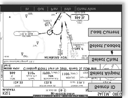
81 71


82 Note The pilot must be aware that not all charts in the loaded database can be used as an overlay. Once the approach chart is loaded, a green Annunciator will illuminate at the top of the screen indicating the airport name and specific chart that has been loaded. Overlay Chart Loading Example 1. Press FN and then MAP or IFR. 2. Press MENU and then the LOAD CHART Line Select key. 3. Highlight the desired airport with the arrow smart keys and then press the SELECT smart key. 4. Highlight the desired approach with the arrow smart keys and then press the LOAD smart key. 72

83 5. Adjust the zoom level using the IN or OUT smart keys. Viewing the Chart as an Overlay Display of Coverage Area Once the desired approach chart has been loaded, a green Annunciator bar with the approach name is illuminated at the top of the Custom and IFR maps. If the aircraft is outside the coverage area of the approach chart, a black rectangular box will be presented that shows the coverage of the chart itself. Once the aircraft has entered the coverage area, the chart contents will be displayed on the screen. Note that a loaded approach chart is only viewable from the maps when the aircraft is in flight, otherwise, the airport surface chart has priority and the approach chart must be viewed from the Chart View function. Chart Zooming Auto zoom mode is supported from the Custom Map and is recommended to reduce the workload associated with maintaining an appropriate zoom level. In auto zoom mode (entered by zooming all the way down or all of the way up), the zoom scale will be calculated to maintain the current destination waypoint of your GPS receiver on the 73
84 screen at all times. The displayed zoom scale can be determined from the range rings on the arc and 360 displays, or from the distance to the displayed destination waypoint. When an approach chart is loaded and being displayed, the auto zoom mode will limit the low-end zoom level to 5 nm as the current waypoint is being approached. This prevents the display from zooming into a level where the overall situational awareness relative to the approach as a whole is lost. This can be over-ridden by taking the unit out of auto zoom mode. Chart Panning Panning on the loaded chart is currently not supported. Entering the panning mode will disable the display of the chart and allow the underlying map layers to be presented. Chart Orientation When the chart overlay is presented, the orientation is identical to the currently selected orientation of the map itself (North up, track up or desired track up) with ownship position correctly geo-referenced and presented on the chart. Note that rotation of the text on the charts themselves is not supported, meaning that text may not be oriented horizontally when displayed in track-up fashion. Chart Info Pressing the INFO key when a chart is loaded will change the smart key labels to Header, Profile, Mins, and Info. Pressing the corresponding keys will allow the different parts of the chart to be presented along the bottom of the screen. Pressing the INFO key will disable this mode and return the menu to the normal map controls. Chart View Function The Chart View Function is accessed by pressing the FN Function key and selecting the Chart View (CHART) function. The Chart View Function incorporates five menu items that control two basic operations: 74

85 Selecting a chart (for static viewing) Loading a chart (for map overlay) The term Selecting a chart is used to designate that a given chart is selected for static viewing on the screen. This is typically done by first specifying the airport, then the specific chart for that airport. The term Loading a chart is used to designate that a given chart is loaded for flight operations and can be used as an actual overlay on the maps. Loading a chart through the Chart View Function is identical to loading a chart from the Custom/IFR map as described in previous sections. All charts within the database, geo-referenced or not, can be statically viewed from the Chart View Function. Only geo-referenced charts can be loaded for map overlay purposes. The Chart View Function will retain the last view set and will not change the chart, zoom level, or pan setting when the function is exited and re-entered, allowing it to operate similar to a physical chart manual. An exception to this is when a chart is loaded in the Custom or IFR Map functions. When this is done, the loaded chart is set as the currently selected chart in the Chart View function. Chart View Example: 1. Press FN and then CHART. 2. Depending on Chart status last used: Press MENU and then the SELECT AIRPORT Line Select key; or 75
86 Highlight the desired airport with the arrow smart keys and then press the SELECT smart key. 3. Highlight the desired chart with the arrow smart keys and then press the LOAD or VIEW smart key. 4. View the chart. Adjust the zoom level using the IN or OUT smart keys. Press the PAN smart key and use the movement Line Select keys on the right side of the display. Use the INFO smart key to step through the different details of the chart. Menu Items Search ID The Search ID menu option within the Chart View Function allow you to search for a specific airport identifier. As this operation requires multiple key-strokes to look up a specific chart, it is not recommended as the primary mechanism for accessing the charts, but does allow for flexibility. When an airport is located, it will be set as the currently selected airport. Airport identifiers can be entered with or without the K prefix. Select Airport The Select Airport operation allows the airport of interest to be selected from a pop-up list. The airports presented in the list are determined based on the final destination waypoint as the first entry, and a nearest type search for the remaining entries. This method allows the airport to be quickly located based on the current flight plan on the external GPS navigator. Once the airport is located, the Select Chart menu is presented (see below), allowing a specific chart for that airport to be either loaded or simply viewed. 76
87 Select Chart The Select Chart operation allows the list of charts for the currently selected airport to be listed in a pop-up list. Within this list, a circular earth symbol indicates that the chart is geo-referenced and therefore can be loaded for use as an overlay on the maps. If a red X is presented through the earth symbol, then that specific chart is not geo-referenced and can be viewed, but not loaded as a map overlay. Select Loaded The Select Loaded operation allows the currently loaded chart to be selected for viewing. This is typically done if a given chart was LOADED from the Custom/IFR Map, and viewing it from the Chart View Function is desired. Note that loading a chart from the Custom/IFR Map will also load and select the chart for viewing. Load Current The Load Current operation allows the current (viewed) approach chart to be set as the loaded approach chart. When this operation is performed, any previously loaded chart is replaced with the chart that is currently being viewed. Airport Surface Charts Airport surface charts provide a graphical presentation of the airport surface area (runways, taxiways, buildings, towers and other objects), within the immediate airport vicinity. From either the Custom Map or the IFR en route Map, airport surface charts will automatically be loaded and displayed as an overlay if the following conditions are met: The airport surface chart is within the loaded database The airport surface chart is geo-referenced by Jeppesen Airport Chart menu layer is turned on 77
88 The aircraft position is within the coverage of the chart A loaded chart is not being flown In typical operation, the above conditions are met when the unit is turned on, meaning that the airport surface map is displayed as soon as GPS position is acquired. Note that the Zoom Scale Auto-Transition feature determines the initial zoom scale that is set when the aircraft is on the ground, which is important when working with surface charts. Viewing Surface Charts The airport surface charts are treated similarly to approach type charts in that they can be viewed through both the Chart View Function and on the Custom Map/IFR Map as an overlay. However, as there is only one unique surface chart for a given airport, it does not need to be manually loaded for display. The nearest available airport surface chart will always be used. When viewed from the Chart View Function, the airport surface chart shows up as the first available chart for the selected airport of interest. Thus, after selecting the airport of interest, the list of charts will have an Airport entry as the first item in the list. As with standard approach charts, when viewed from the Chart View Function, the aircraft s ownship position is not shown on the airport surface chart. If an approach chart is currently loaded and being displayed (aircraft is in the air), it will take priority over displaying the airport surface chart. Once the aircraft touches down and the speed drops below the air/ground threshold, it is assumed that a missed approach procedure is not needed. At this point, the approach chart is un-loaded and the airport surface chart is displayed. While on the ground, airport surface charts will take priority over any loaded approach chart. 78
89 Operational Considerations When to Load a Chart An approach chart can be loaded at any point during the flight, including on the ground before takeoff. The only by-product of loading an approach before takeoff is if the aircraft exceeds the air/ground speed threshold, then drops back below this threshold, the approach will be automatically un-loaded as the system thinks the flight has occurred and the aircraft has landed again. Note that the approach will not be shown on the map itself until the aircraft has become airborne. Flying an Approach It is important to recognize that the charts function is not intended to provide guidance information for flying an approach. Its intended function is to provide basic situational awareness as to your current position relative to the approach as a whole. Standard instruments MUST be used to actually provide the navigational information required under IFR conditions. Approach to Surface Map Transitions Logic is incorporated that will automatically transition the display from an in-flight approach chart display to a zoomed in view of the airport surface chart upon landing. The intent is to provide a hands-free transition from the approach phase of flight to the airport surface navigation phase without having to manually un-load the approach and adjust the zoom scale. The transition logic is based solely on aircraft ground speed. When an approach chart is loaded and being flown, and the aircraft ground speed drops below the air/ground threshold (set from within the SYS Function), it is assumed that a landing has been performed. At this point, the loaded approach chart is automatically unloaded and 79
90 the airport surface chart will be presented on the screen showing runways, taxiways, etc. However, if approach chart is loaded and being flown and the aircraft crosses the missed approach point without slowing, it is assumed that a missed approach procedure is being performed. In this case, the automatic transition to surface maps does not occur and the approach is not automatically un-loaded. See the Initial Zoom and Transition Speed selection in the System Function (Page 88). Chart NOTAMS Any applicable NOTAMS that apply for a given chart are shown under the INFO key when that chart is selected. The chart should be viewed for NOTAMS before use. Important System Limitations Note that while on the ground and viewing airport surface charts, the display can be oriented in the Track Up mode. In this mode, the last known GPS-based track as obtained from the external GPS navigation system is used to orient the map. GPS track is typically not accurate at low speeds and does not reflect the actual heading of the aircraft at all times. Invert Option As with the basic maps, the chart image can be inverted using the standard invert key. Typical Operational Scenario The following scenarios makes the assumption that: The appropriate charts are available and geo-referenced The default ground zoom level is set to 0.5nm The default air zoom level is set to AUTO Typical Taxi Scenario On power up and GPS position acquisition, the Custom Map Function will show the aircraft on the surface chart at a zoom level of 0.5nm. The aircraft will be shown 80
91 relative to taxiways and runways throughout the taxi procedure. Typical Takeoff Scenario On takeoff roll, when the aircraft reaches the air/ground speed threshold, the display will automatically transition to the en route zoom mode of AUTO and adjust the display to show the current destination waypoint. Typical Approach Scenario Setting the destination waypoint to the destination airport on the GPS navigation system and pressing LOAD CHART from the Custom/IFR Map will present the destination airport in the selection list. Selecting this airport will then bring up the approach charts that are available for that airport, which can then be loaded by pressing the LOAD smart key. Typical Landing Scenario With an approach chart being flown, upon touchdown and rollout, the chart will be unloaded and the map will automatically switch to the airport surface chart with the zoom level set to 0.5nm. 81


92 Radar Function The MX20 I/O Radar product supports an interface for the Allied Signal / Bendix-King ART2000 weather radar. The ART2000 weather radar is seamlessly integrated with the other functionality of the MX20 with a RADAR option available from the main function menu. 82
93 The MX20 operates as both a display and radar control head, allowing direct replacement of older display systems. Multiple modes and features of the ART2000 are supporting including Weather Mode, Ground Mapping Mode, Horizontal Display Mode, Vertical Display Mode, Hold Mode, Tilt Control, Bearing Control, Range Control, Bearing Cursor support, Tilt Cursor support, and Radar Stabilization. On initial power-up and entry to the Radar Function, the unit will be in the OFF mode. Selections can be made to command the unit into one of the following initial modes: STBY ON TEST OFF Once activated, the different operating modes of the radar are selected by pushing the corresponding line select keys. Descriptions of the different modes are as follows, with the currently selected mode being highlighted in green: Off Mode On MX20 power-up, the radar antenna is placed in the OFF mode. In this mode, the radar antenna head is not energized and is not transmitting. Standby Mode In the standby mode, the radar head is powered up, but is not transmitting. Placing the unit into standby mode initiates the warm-up sequence that is required by the transmitter within the radar head assembly. Weather Mode In the weather (WX) mode, the antenna is transmitting and painting reflected returns on the screen. This mode is intended for painting airborne weather and is the normal operating mode for the unit. Radar returns are painted in the following colors: 83
94 Black Green Yellow Red Magenta Black is the weakest return while Magenta shows where the strongest returns were obtained. While in the weather mode (or any other time the radar is transmitting), a green RDR indicator is presented in the upper left corner of the display. MAP Mode The Map (MAP) mode is used for obtaining returns from the ground. In this mode, the return data is rendered in the following colors: Black Cyan Green Yellow Magenta While in the Map mode, the gain can be adjusted (see below). Horizontal Mode The Horizontal Mode (HORIZ) commands the radar head to scan in the horizontal plane at a pilot selectable tilt angle. In this mode, the current Tilt angle is shown on the lower half of the display in green. Vertical Mode The Vertical Mode (VERT) commands the radar head to scan in the vertical plane at a pilot selectable bearing off of the nose of the aircraft. In this mode, the current Bearing angle is shown on the lower half of the display in green. Tilt Control The Tilt (TILT) control is used to adjust the current tilt angle of the radar head when horizontal sweeping is being 84
95 performed. The value can be adjusted from a +15 to 15 degree range. Bearing Control The Bearing (BRG) control is used to adjust the current bearing angle of the radar head when vertical sweeping is being performed. The value can be adjust from 45L to 45R. Gain Control Available only when the MAP mode is current, the gain is used to adjust the sensitivity of the radar receiver. It can be used in map mode to adjust the characteristics of the returns from the surface. Hold Control The Hold mode is used to freeze the display. While in the hold mode, the green RDR indicator flashes, indicated that the display is not being updated. Radar Smart Key Operations Range Smart Keys The range can be adjusted using the RNG UP and RNG DOWN keys. Values of 10nm to 240 nm can be selected. Tilt While in the Horizontal mode, the tilt is adjusted using the TILT UP and TILT DOWN smart keys. Bearing While in the Vertical mode, the bearing is adjusted using the BRG RIGHT and BRG LEFT smart keys. Gain While in the Ground mode, the gain is adjusted using the GAIN UP and GAIN DOWN smart keys. Cursor Pre-Select Operation Cursor pre-select option can be used to pre-select a bearing or tilt angle prior to switching the vertical or horizontal scan mode of the display. The cursor is a cyan line extending along the Radar s projected path and can be displayed in both the horizontal and vertical modes. 85
96 For example, if horizontal scanning is occurring, a cursor line can be activated to pre-select a specific bearing to a weather cell of interest. Once selected, changing the scan mode to vertical will automatically set the bearing of the vertical sweeps to the bearing previously indicated by the cursor line. Conversely, if vertical scanning is occurring, a cursor line can be activated to pre-select a specific tilt to a weather cell of interest. Once selected, changing the scan mode to horizontal will automatically set the tilt angle of the horizontal sweeps to the tilt angle previously indicated by the cursor line. The bearing cursor is activated any time the Tilt/Bearing control is changed from its default position. Radar Menu Functions Pressing the MENU key while in the Radar Function allows the stabilization to be turned on or off. The currently selected mode is displayed at the top of the radar screen during normal operations. Additional status information is also shown while the radar menu is active. Radar Return Signals Interpreting radar return signals is beyond the scope of this manual. Please refer to the radar user s guide for details on interpreting radar data. 86

97 System Function The System function allows you to set general Nav preferences, obtain version information, and perform tests on the operation of your MX20. System Nav Page Ownship Symbol The Ownship Symbol option allows you to choose the type of icon that will represent your aircraft on the display. You can make selections of Single, Twin, Jet, or Helicopter. Lat/Lon Format The Lat/Lon format option allows you to select between two choices for the display of Lat/Lon coordinates. Choose between degrees-minutes-seconds-seconds decimals (DD MM SS.SS) or degrees-minutes-minutes decimals (DD MM.MM). Set Baro Units Baro-Correction (QNH) can now be entered in Millibars in addition to Hg. This preference is set under the SYS function. 87

98 Set Baro Correction You may enter the corrected barometric pressure so that the proper pressure altitude will be displayed. 1. Press the LINE SELECT key for Set Baro Correction. 2. The Function smart keys at the bottom of the display will have direction arrows above them. Press the UP/DOWN arrow keys to change the value of the highlighted number. Press the LEFT/RIGHT arrow keys to move to another number. 3. Press MENU/ENTER to save the changed values and leave the Set Baro Correction option. Display Lat/Lon Lines Use this option to choose to display or not display Lat/Lon lines on the map displays. Initial Zoom and Transition Speed A zoom scale auto-transition point is supported that helps to reduce the pilot workload by automating the selection of the zoom scale based on the phase of flight. The two transitions are: Ground-to-Air mode (Takeoff) Air-to-Ground mode (Landing) When the aircraft transitions from Ground-to-Air, the zoom scale is automatically set to a user selected en route zoom scale. When the aircraft transitions from Air-to-Ground, the zoom scale is automatically set to a 88

99 user selected Ground zoom scale. The transition point is based on a user selected En Route/Ground Transition Speed and is based on GPS ground speed. The Auto-Transition feature allows for optimal close-in viewing while on the ground and optimal long range viewing while in flight, without the user having to make manual zoom scale adjustments while in the takeoff and landing phases of flight. The Zoom scale is shown in the lower left corner of the display. The En Route and Ground zoom scales and the transition point are adjusted under the SYS Function (NAV Options - Page 2). In the SYS Function (NAV Options - Page 2) Menu the choices are: En Route/Ground Transition Speed kts Initial en route Zoom Scale Auto, nm Initial Ground Zoom Scale nm 89
100 The recommended settings for the initial zoom scales are Auto for the en route mode and 0.5 nm for the ground mode. 1. Press FN until you see the SYS function key. 2. Press the SYS function key. 3. With the NAV selection highlighted press MENU. 4. Press the NEXT PAGE Line Selection key. 5. Press the Line Selection keys as needed to select the settings. Press ENT to save your settings. 90

101 System Info The System Info page includes information about the software and database versions of the MX20. The data port status is also displayed. The Data port status description allows you to verify correct system installation and to monitor the health of each of the devices sending information to the MX20. Use this information when you contact your dealer or the factory. GPS and Datalink Status For GPS/UAT equipped installs, the SYS/INFO page now shows additional details for both the internal GPS engine and the data-link status. GPS satellite usage and signal strength are presented in the upper right of the info page in addition to each satellite s position in the sky. If no GPS is installed in the MX20, the text Internal GPS Not Available will be shown. Data-link information is monitored as follows: HB ADS-B TIS-B FIS TX FIS WX Heart-Beat from the UAT data-link radio ADS-B broadcast packets received TIS-B broadcast packets received Textual weather data packets received Graphical weather data packets received 91

102 System Test Page The System Test Page allows you to test the display of the MX20 to ensure proper operation. 92

103 Test Pattern 1 The Test Pattern option displays a number of patterns and colors to test the MX20 display. Use this option to verify proper operation of the display or when contacting Customer Service. Red, Green, Blue, White Test Pattern Choosing the Red, Green, Blue, or White options floods the screen with the selected color. Use this option to verify proper operation of the display or when contacting UPS Aviation Technologies Customer Service. 93
2000 by UPS Aviation Technologies, Inc. All rights reserved. Printed in the U.S.A.
 No part of this document may be reproduced in any form or by any means without the express written consent of UPS Aviation Technologies, Inc. UPS Aviation Technologies, Inc., II Morrow, and Apollo are
2000 by UPS Aviation Technologies, Inc. All rights reserved. Printed in the U.S.A.
 No part of this document may be reproduced in any form or by any means without the express written consent of UPS Aviation Technologies, Inc. UPS Aviation Technologies, Inc., II Morrow, and Apollo are
MX20 TM. color Multi-Function Display pilot s guide
 MX20 TM color Multi-Function Display pilot s guide 2005 Garmin Ltd. or its subsidiaries Garmin International, Inc. Garmin AT 1200 East 151 st Street, Olathe, Kansas 66062, U.S.A. 2345 Turner Rd., SE Salem,
GMX 200 TM. Pilot s Guide & Reference
 GMX 200 TM Pilot s Guide & Reference 2006-2015 Garmin Ltd. or its subsidiaries Garmin International, Inc., 1200 East 151st Street, Olathe, KS 66062, U.S.A. Tel: 913/397.8200 Fax: 913/397.8282 Garmin AT,
GNS 430 Basic Usage. VFR GPS Usage
 GNS 430 Basic Usage VFR GPS Usage Disclaimer This briefing is to designed to give an introductory overview so that as you read the GNS 430 Pilot s Guide and Reference you will have a basic understanding
Basic GPS Operation. by Greg Whiley. Another practical publication from Aussie Star Flight Simulation
 Basic GPS Operation by Greg Whiley Another practical publication from Aussie Star Flight Simulation INTENTIONALLY LEFT BLANK Aussie Star Flight Simulation 2 Basic GPS Operations Statement of copyright
KMD 550/850. Traffic Avoidance Function (TCAS/TAS/TIS) Pilot s Guide Addendum. Multi-Function Display. For Software Version 01/13 or later
 Pilot s Guide Addendum. Multi-Function Display. For Software Version 01/13 or later") N B KMD 550/850 Multi-Function Display Traffic Avoidance Function (TCAS/TAS/TIS) Pilot s Guide Addendum For Software Version 01/13 or later Revision 3 Jun/2004 006-18238-0000 The information contained
N B KMD 550/850 Multi-Function Display Traffic Avoidance Function (TCAS/TAS/TIS) Pilot s Guide Addendum For Software Version 01/13 or later Revision 3 Jun/2004 006-18238-0000 The information contained
This page is intentionally blank. GARMIN G1000 SYNTHETIC VISION AND PATHWAYS OPTION Rev 1 Page 2 of 27
 This page is intentionally blank. 190-00492-15 Rev 1 Page 2 of 27 Revision Number Page Number(s) LOG OF REVISIONS Description FAA Approved Date of Approval 1 All Initial Release See Page 1 See Page 1 190-00492-15
400W / 500W Series Display Interfaces
 400W / 500W Series Display Interfaces Pilot s Guide Addendum L-3 STORMSCOPE WX-500 Weather Mapping Sensor L-3 SKYWATCH Traffic Advisory System (Model SKY497) L-3 SKYWATCH HP Traffic Advisory System (Model
U.S.A. Toll Free Canada Toll Free International FAX
 No part of this document may be reproduced in any form or by any means without the express written consent of II Morrow Inc. II Morrow and Apollo are trademarks of II Morrow Inc. 1997 by II Morrow Inc.
Apollo GPS Database Addendum
 Apollo GPS Database Addendum This document includes information that has been added to the waypoint database after the printing of the user s guide. A new waypoint type has been added to your database
GTX 320A. Mode A/C Transponder. pilot s guide
 GTX 320A Mode A/C Transponder pilot s guide 2000 GARMIN Corporation GARMIN International, Inc. 1200 East 151 st Street, Olathe, Kansas 66062, U.S.A. Tel. 913/397.8200 or 800/800.1020 Fax 913/397.8282 GARMIN
400/500 Series Display Interfaces
 400/500 Series Display Interfaces Pilot s Guide Addendum Goodrich STORMSCOPE WX-500 Series II Weather Mapping Sensor Goodrich SKYWATCH Traffic Advisory System (Model SKY497) Goodrich SKYWATCH HP Traffic
ENSTROM 480/480B OPERATOR S MANUAL AND FAA APPROVED ROTORCRAFT FLIGHT MANUAL SUPPLEMENT GARMIN GNS 430W/530W NAVIGATION SYSTEM
 ENSTROM 480/480B OPERATOR S MANUAL AND FAA APPROVED ROTORCRAFT FLIGHT MANUAL SUPPLEMENT GARMIN GNS 430W/530W NAVIGATION SYSTEM * * * * * REPORT NO. 28-AC-055 HELICOPTER SERIAL NO. HELICOPTER REGISTRATION
Pilot s Guide KI 825. Bendix/King Safety Display System Electronic Horizontal Situation Indicator For Units Having -2, -3 and -4 Softwa re
 N Pilot s Guide KI 825 Bendix/King Safety Display System Electronic Horizontal Situation Indicator For Units Having -2, -3 and -4 Softwa re W A R N I N G The enclosed technical data is eligible for export
Multi-Function Display Pilot s Guide
 Multi-Function Display Pilot s Guide 600-00078-000 Rev 09 Document Review History Date Revision Description 12/13/02 00 Initial Release per ECO 02-363 1/30/03 01 Revised per ECO 03-038 2/10/03 02 Revised
How to Intercept a Radial Outbound
 How to Intercept a Radial Outbound by Greg Whiley Another practical publication from Aussie Star Flight Simulation How to intercepting a radial outbound 1 Greg Whiley Aussie Star Flight Simulation How
SUPPLEMENT REVISION CESSNA MODEL 182T
 SUPPLEMENT REVISION CESSNA MODEL 182T NAV III AVIONICS OPTION - Serials 18281228 and 18281318 thru 18281868 and 18281870 thru 18281875 PILOTS OPERATING HANDBOOK AND AIRPLANE FLIGHT MANUAL REVISION 1 1
standby and to begin tracking traffic. 3. To display weather, traffic, & lightning, select the DISP MD WX-T[C]AS and SECTOR
![standby and to begin tracking traffic. 3. To display weather, traffic, & lightning, select the DISP MD WX-T[C]AS and SECTOR](/thumbs/84/91000608.jpg "standby and to begin tracking traffic. 3. To display weather, traffic, & lightning, select the DISP MD WX-T[C]AS and SECTOR") Quick Start Instructions This page explains how to turn on the RGC250 and switch between s. Refer to Selecting Menu Items at the bottom of the page as needed. or traffic information may not be available
Quick Start Instructions This page explains how to turn on the RGC250 and switch between s. Refer to Selecting Menu Items at the bottom of the page as needed. or traffic information may not be available
400/500 Series GTS 8XX Interface. Pilot s Guide Addendum
 400/500 Series GTS 8XX Interface Pilot s Guide Addendum Copyright 2010 Garmin Ltd. or its subsidiaries. All rights reserved. This manual reflects the operation of Software version 5.03 or later for 4XX
UM DALI getting started guide. Document information
 Rev. 1 6 March 2012 User manual Document information Info Keywords Abstract Content LPC111x, LPC1343, ARM, Cortex M0/M3, DALI, USB, lighting control, USB to DALI interface. This user manual explains how
GNS 430(A) Pilot s Guide and Reference
 Pilot s Guide and Reference") GNS 430(A) Pilot s Guide and Reference RECORD OF REVISIONS Revision Date of Revision Description A 12/98 Initial Release B 4/99 Update to conform to recent SW changes C 6/99 Added Addendum D 7/99 Update
GNS 430(A) Pilot s Guide and Reference RECORD OF REVISIONS Revision Date of Revision Description A 12/98 Initial Release B 4/99 Update to conform to recent SW changes C 6/99 Added Addendum D 7/99 Update
AP OL LO SL 60 VHF Communications Transceiver and GNSS (GPS) Navigation Receiver
 Navigation Receiver") SkyRentals INFO FOR VH-VMA Insert to SECTION 9 MODEL 182Q (1977) VHF Com1 & GNSS Nav Receiver AP OL LO SL 60 VHF Communications Transceiver and GNSS (GPS) Navigation Receiver VHF Com1 & GNSS Nav components
SkyRentals INFO FOR VH-VMA Insert to SECTION 9 MODEL 182Q (1977) VHF Com1 & GNSS Nav Receiver AP OL LO SL 60 VHF Communications Transceiver and GNSS (GPS) Navigation Receiver VHF Com1 & GNSS Nav components
2001 by UPS Aviation Technologies, Inc. All rights reserved. Printed in the U.S.A.
 No part of this document may be reproduced in any form or by any means without the express written consent of UPS Aviation Technologies, Inc. II Morrow and Apollo are trademarks of UPS Aviation Technologies,
LOG OF REVISIONS Rev 1 RFMS, Eurocopter EC130 B4 G500H System. Page Date Number Description FAA Approved.
 Revision Number LOG OF REVISIONS Page Date Number Description FAA Approved 1 05/15/2014 All Complete Supplement See page 1 190-01527-16 Rev 1 RFMS, Eurocopter EC130 B4 G500H System Page 2 of 25 FAA APPROVED
GMA 240 Pilot s Guide
 GMA 240 Pilot s Guide Copyright 2008 Garmin Ltd. or its subsidiaries. All rights reserved. This manual reflects the operation of GMA 240 units with mod level 0 or later. Some differences in operation may
KGX 150/130 ADS -B Certified Transceivers & Receivers
 BendixKing By Honeywell 9201 -B San Mateo Blvd. NE Albuquerque, NM 87113 U.S.A. CAGE: 6PC31 Telephone: 1-505 -903-6148 Telephone: 1-855 -250-7027 (Toll Free in U.S.A.) Web site: http://www.bendixking.com
Introduction. Traffic Symbology. System Description SECTION 12 ADDITIONAL FEATURES
 12.2 Traffic Advisory Systems (TAS) Introduction All information in this section pertains to the display and control of the Garmin GNS 430/GTS 800 interface. NOTE: This section assumes the user has experience
Integrated Cockpit Display System ICDS 1000 Pilot Operation Handbook
 Integrated Cockpit Display System ICDS 1000 Pilot Operation Handbook ICDS1000 Pilot Operating Handbook Revision 1.3 572-0540 page 1 Table Of Contents Electronic Attitude Direction Indicator (EADI)... 8
ENSTROM 480B OPERATOR S MANUAL AND FAA APPROVED ROTORCRAFT FLIGHT MANUAL SUPPLEMENT GARMIN GTN 650 NAVIGATION SYSTEM
 ENSTROM 480B OPERATOR S MANUAL AND FAA APPROVED ROTORCRAFT FLIGHT MANUAL SUPPLEMENT GARMIN GTN 650 NAVIGATION SYSTEM * * * * * REPORT NO. 28-AC-064 HELICOPTER SERIAL NO. HELICOPTER REGISTRATION NO. * *
AT01 AIRPLANE FLIGHT MANUAL
 Table of Contents Supplement AVE12 1. Section 1 General AVE12 3 2. Section 2 Operating Limitations AVE12 3 3. Section 3 Emergency Procedures AVE12 3 4. Section 4 Normal Procedures AVE12 4 5. Section 5
UM DALI getting started guide. Document information
 Rev. 2 6 March 2013 User manual Document information Info Content Keywords LPC111x, LPC1343, ARM, Cortex M0/M3, DALI, USB, lighting control, USB to DALI interface. Abstract This user manual explains how
ER200 COMPACT EMERGENCY CRANK DIGITAL WEATHER ALERT RADIO OWNER S MANUAL
 ER200 COMPACT EMERGENCY CRANK DIGITAL WEATHER ALERT RADIO OWNER S MANUAL Table of Contents -------------------------------------- 2 Features ----------------------------------------------- 3 Controls and
SN4500. Pilot s Guide. Primary Navigation Display. Reversionary Attitude Mode. with. (This page intentionally left blank)
") SN4500 Primary Navigation Display with Reversionary Attitude Mode (This page intentionally left blank) Pilot s Guide 82009-PG, REV D1 SANDEL SN4500 PILOT S GUIDE PAGE II Pilot information Publication Date:
SN4500 Primary Navigation Display with Reversionary Attitude Mode (This page intentionally left blank) Pilot s Guide 82009-PG, REV D1 SANDEL SN4500 PILOT S GUIDE PAGE II Pilot information Publication Date:
Cockpit GPS Quick Start Guide
 Cockpit GPS Quick Start Guide Introduction My online book, Cockpit GPS, has grown to over 250 pages. I have that much information because at one time or another I thought that each piece would be useful
SIR-WRR1. User's Guide SIRIUS Echo Antenna. Signal Repeater System Accessory
 SIR-WRR1 User's Guide SIRIUS Echo Antenna Signal Repeater System Accessory Desktop SIRIUS Docking Echo Station Antenna FCC NOTICE: This device complies with part 15 of the FCC Rules and with RSS-210 of
Using the USB Output Port to Charge a Device
 Table of Contents ----------------------------------- 2 Features ----------------------------------------------- 3 Controls and Functions ---------------------------------- 4 ER210 Power Sources -----------------------------------
RUSH G1 MECHANICAL KEYBOARD PRODUCT MANUAL V.14
 RUSH G1 MECHANICAL KEYBOARD V.14 SOFTWARE INSTALLATION DOWNLOAD SOFTWARE INSTALLER From: http://download.fnatic.com RUN THE INSTALLER ACCEPT POP UPS If you are prompted by any pop ups during the installation,
P/N 135A FAA Approved: 7/26/2005 Section 9 Initial Release Page 1 of 10
 FAA APPROVED AIRPLANE FLIGHT MANUAL SUPPLEMENT FOR GARMIN GNS 430 - VHF COMM/NAV/GPS Serial No: Registration No: When installing the Garmin GNS 430 - VHF COMM/NAV/GPS in the Liberty Aerospace XL2, this
GTN 725/750. Map. Traffic. Terrain. Weather. Charts. Flight Plan. Procedures. Nearest. Waypoint Info. Services. Utilities. System
 Map Traffic Terrain TN 725/750 Cockpit Reference uide Weather Charts Flight Plan Procedures Nearest Waypoint Info Services Utilities System Warnings, Cautions, and Notes WARNIN: Navigation and terrain
SN3500 EHSI. Pilot s Guide Effectivity and Errata. (This page intentionally blank)
") SN3500 EHSI (This page intentionally blank) Pilot s Guide Effectivity and Errata Insert this update ahead of the cover page of the Pilot s Guide referenced below. Date: Effectivity: 03-JUL-2014 SN3500
SN3500 EHSI (This page intentionally blank) Pilot s Guide Effectivity and Errata Insert this update ahead of the cover page of the Pilot s Guide referenced below. Date: Effectivity: 03-JUL-2014 SN3500
Description of Change T--1 Updated to reflect Revision 3. RR--1 Updated to reflect Revision 3. LEP--1 thru LEP--8. Updated to reflect Revision 3.
 BendixKing By Honeywell 9201 -B San Mateo Blvd. NE Albuquerque, NM 87113 U.S.A. CAGE: 6PC31 Telephone: 1-602 -365-7027 Telephone: 1-855 -250-7027 (Toll Free in U.S.A.) TO: HOLERS OF THE KSN 765/770 INTEGRATE
AIRPLANE FLIGHT MANUAL AQUILA AT01. Date of Issue A.01 Initial Issue (minor change MB-AT ) all March
 all March") 0.1 LIST OF REVISIONS AND AMENDMENTS Revision Reason for Amendment/Revision Affected Pages Date of Issue A.01 Initial Issue (minor change MB-AT01-00297) all 2009 19. March 0.2 LIST OF EFFECTIVE PAGES Page
0.1 LIST OF REVISIONS AND AMENDMENTS Revision Reason for Amendment/Revision Affected Pages Date of Issue A.01 Initial Issue (minor change MB-AT01-00297) all 2009 19. March 0.2 LIST OF EFFECTIVE PAGES Page
FlightMax Flight Situation Display
 FlightMax Flight Situation Display Pilot s Guide Part Number: 600-0053 Revision 00 55 Old Bedford Road Lincoln, Massachusetts 01773 Telephone: (781) 402-7400 Fax: (781) 402-7599 Web Site: www.avidyne.com
SD3-60 AIRCRAFT MAINTENANCE MANUAL SYSTEM (BENDIX RDR 1150 COLOUR) - DESCRIPTION & OPERATION
 - DESCRIPTION & OPERATION") AMM 41.0.0.0WEATHER RADAR SYSTEM (BENDIX RDR 1150 COLOUR) - DESCRIPTION & OPERATION 1. Description A. General The Weather Radar System, Bendix type RDR-1150 (colour), is installed to provide continuous
AMM 41.0.0.0WEATHER RADAR SYSTEM (BENDIX RDR 1150 COLOUR) - DESCRIPTION & OPERATION 1. Description A. General The Weather Radar System, Bendix type RDR-1150 (colour), is installed to provide continuous
Apollo Model SL10 Series Audio Selector Panel User s Guide
 Apollo Model SL10 Series Audio Selector Panel December 2001 560-0973-00a No part of this document may be reproduced in any form or by any means without the express written consent of UPS Aviation Technologies,
Table of Contents. Introduction 3. Pictorials of the 40 and 50 Systems 4. List of Applicable Acronyms 6
 Table of Contents Introduction 3 Pictorials of the 40 and 50 Systems 4 List of Applicable Acronyms 6 System 40 Modes of Operation 7 System 40 Functional Preflight Procedures 10 System 40 In Flight Procedures
GTS Traffic Systems. Pilot s Guide
 GTS Traffic Systems Pilot s Guide 2014 Garmin Ltd. or its subsidiaries. All rights reserved. Garmin International, Inc., 1200 East 151st Street, Olathe, KS 66062, U.S.A. Tel: 913/397.8200 Fax: 913/397.8282
The Alaska Air Carriers Association. Supports and Advocates for the Commercial Aviation Community
 The Alaska Air Carriers Association Supports and Advocates for the Commercial Aviation Community The Alaska Air Carriers Association membership includes Part 121, 135, 125 and commercial Part 91 air operators.
USER GUIDE LAST UPDATED DECEMBER 15, REX GAME STUDIOS, LLC Page 2
 USER GUIDE LAST UPDATED DECEMBER 15, 2016 REX GAME STUDIOS, LLC Page 2 Table of Contents Introduction to REX Worldwide Airports HD...3 CHAPTER 1 - Program Start...4 CHAPTER 2 - Setup Assistant...5 CHAPTER
Chapter 10 Navigation
 Chapter 10 Navigation Table of Contents VHF Omnidirectional Range (VOR) VOR Orientation Course Determination VOR Airways VOR Receiver Check Points Automatic Direction Finder (ADF) Global Positioning System
GTN 650/750 SERIES SW V4.00 UPGRADE SUPPLEMENT
 GTN 650/750 SERIES SW V4.00 UPGRADE SUPPLEMENT The Pilot s Guides have been revised for SW Version 4.00. This supplement provides information regarding new features of software version 4.00 for GTN 6XX/7XX
GDL 69/69A XM Satellite Radio Activation Instructions
 GDL 69/69A XM Satellite Radio Activation Instructions 190-00355-04 2008 Rev. H This Page Intentionally Left Blank 2004-2008 Garmin Ltd. or its subsidiaries All Rights Reserved Except as expressly provided
There s a Lynx NGT-series solution to fit any need. MODEL COMPARISON. ADS B Out MHz Mode S ES. p p p p. ADS B In. 978 MHz UAT p p p p
 There s a Lynx NGT-series solution to fit any need. MODEL COMPARISON ADS B Out LYNX NGT-9000 NGT-9000+ NGT-9000D NGT-9000D+ 1090 MHz Mode S ES ADS B In 978 MHz UAT 1090 MHz Internal WAAS/GPS Wi-Fi Capable
SN3500 EHSI. Pilot s Guide Effectivity and Errata. Instructions
 SN3500 EHSI Pilot s Guide Effectivity and Errata Insert this update ahead of the cover page of the Pilot s Guide referenced below. Date: Effectivity: 05-OCT-2018 SN3500 Software Version 4.05, A4.08 Pilots
NAVIGATION INTRUMENTATION ADF
 1. Introduction NAVIGATION INTRUMENTATION ADF The Automatic Direction Finding (ADF) equipment on-board of aircraft is used together with the Non Directional Beacon (NDB) transmitters installed on the ground.
GTN 725/750. Map. Traffic. Terrain. Weather. Charts. Flight Plan. Procedures. Nearest. Waypoint Info. Services. Utilities. System
 Map Traffic Terrain GTN 725/750 Cockpit Reference Guide (CRG) Weather Charts Flight Plan Procedures Nearest Waypoint Info Services Utilities System Warnings, Cautions, and Notes WARNING: Navigation and
Microair Avionics Pty Ltd Airport Drive Bundaberg Queensland 4670 Australia Tel: Fax:
 Microair Avionics Pty Ltd Airport Drive Bundaberg Queensland 4670 Australia Tel: +61 7 41 553048 Fax: +61 7 41 553049 e-mail: support@microair.com.au About This Document Microair Avionics have developed
Universal ADS-B Receiver. Equipment Supplement
 Universal ADS-B Receiver Equipment Supplement Revision A 17-Mar-2016 Revision Notes Revision Date Change Description A 05/03/17 Initial Release ADS-B Receiver Supplement 2 Table of Contents Section 1:
MOONEY AIRCRAFT CORPORATION P. 0. Box 72 Kerrville, Texas FAA APPROVED
 P. 0. Box 72 Kerrville, Texas 78029 FAA APPROVED AIRPLANE FLIGHT MANUAL SUPPLEMENT FOR MOONEY M20J, M20K, M20L, M20M, M20R with Aircraft Serial No. Aircraft Reg. No. This supplement must be attached to
Automatic Dependent Surveillance -ADS-B
 ASECNA Workshop on ADS-B (Dakar, Senegal, 22 to 23 July 2014) Automatic Dependent Surveillance -ADS-B Presented by FX SALAMBANGA Regional Officer, CNS WACAF OUTLINE I Definition II Principles III Architecture
Pilot s Operating Handbook Supplement AS-21
 SECTION 9 Pilot s Operating Handbook Supplement Mode S Transponder GARMIN GTX 335 / GTX 345 This supplement is applicable and must be inserted into Section 9 of the POH when a GARMIN GTX 335 or GTX 345
GTN 625/635/650. Map. Traffic. Terrain. Weather. Default NAV. Flight Plan. Procedures. Nearest. Waypoint Info. Services. Utilities.
 Map GTN 625/635/650 Cockpit Reference Guide Traffic Terrain Weather Default NAV Flight Plan Procedures Nearest Waypoint Info Services Utilities System Warnings, Cautions, and Notes WARNING: Navigation
NAVIGATION INSTRUMENTS - BASICS
 NAVIGATION INSTRUMENTS - BASICS 1. Introduction Several radio-navigation instruments equip the different airplanes available in our flight simulators software. The type of instrument that can be found
AWOS Net User s Manual
 Automated Weather Observing System AWOS Net User s Manual 3211-001 Rev. A All Weather Inc. 1165 National Drive Sacramento, CA 95834 USA 800.824.5873 www.allweatherinc.com Copyright 2011 2018, All Weather,
Technical Bulletin April Opticom GPS System. Vehicle connections and configuration to obtain serial GPS data for other devices
 Technical Bulletin April 2011 Opticom GPS System Vehicle connections and configuration to obtain serial GPS data for other devices Intended Use The Opticom GPS System is intended to assist authorized priority
Acu-Park TM. user s guide Directed Electronics, Inc. Vista, CA N9100T 09-04
 Acu-Park TM user s guide 2004 Directed Electronics, Inc. Vista, CA N9100T 09-04 limited one year warranty Directed Electronics, Inc. (hereinafter "Directed") promises to the original purchaser that this
Jasmine Memory Calculations MB87P2020-A
 Application Note Jasmine Memory Calculations MB87P2020-A Fujitsu Microelectronics Europe GmbH History Date Author Version Comment 17/10/03 MMu V1.0 First version 1 Warranty and Disclaimer To the maximum
BASIC USER GUIDE BASIC USER GUIDE CONTENTS. GeneralInformation... 2
 GP360 GP360 1 2 7 8 12 3 4 5 9 10 11 13 6 CONTENTS GeneralInformation... 2 Operation and Control Functions..... 2 Radio Controls...................... 2 Audio Signal Tones.................. 3 Programmable
SkyView. Autopilot In-Flight Tuning Guide. This product is not approved for installation in type certificated aircraft
 SkyView Autopilot In-Flight Tuning Guide This product is not approved for installation in type certificated aircraft Document 102064-000, Revision B For use with firmware version 10.0 March, 2014 Copyright
GRT Autopilot User Guide. All GRT EFIS Systems
 All GRT EFIS Systems Revision A 22-May-2014 Copyright 2014 3133 Madison Ave. SE Wyoming, MI 49548 (616) 245-7700 www.grtavionics.com Revision Notes Revision Date Change Description A 22-May-2014 Complete
MedRx Avant Polar HIT AH-I-MPHITS-5 Effective 11/07/11
 INSTALLATION MANUAL 2 Contents Getting To Know Your AVANT POLAR HIT TM... 4 Setting up the System... 6 Software Installation... 7 Driver Installation Windows 7... 10 Driver Installation Windows XP... 13
GTS 8XX Series. Pilot s Guide Traffic Advisory System
 GTS 8XX Series Pilot s Guide Traffic Advisory System 2009 Garmin Ltd. or its subsidiaries. All rights reserved. Garmin International, Inc., 1200 East 151st Street, Olathe, KS 66062, U.S.A. Tel: 913/397.8200
AUDIO MODE SELECTOR MODEL AMS-6000
 AUDIO MODE SELECTOR MODEL AMS-6000 Installation and Operating Instructions Til Document No. 03RE325 Rev. n/c Issue 4 August 2007 Technisonic Industries Limited 240 Traders Boulevard, Mississauga, Ontario
G1000 Integrated Flight Deck. Cockpit Reference Guide for the Cessna Citation Mustang
 G1000 Integrated Flight Deck Cockpit Reference Guide for the Cessna Citation Mustang FLIGHT INSTRUMENTS NAV/COM/TRANSPONDER/AUDIO PANEL AUTOMATIC FLIGHT CONTROL SYSTEM GPS NAVIGATION FLIGHT PLANNING PROCEDURES
Copyright Information
 PILOT S GUIDE Copyright Information Stratus 3 Pilot s Guide, 2018 Appareo Systems, LLC. All Rights Reserved. All content within is copyrighted by Appareo Systems, LLC and may not be reprinted without permission.
GTN 625/635/650. Map. Traffic. Terrain. Weather. Default NAV. Flight Plan. Procedures. Nearest. Waypoint Info. Services. Utilities.
 Map GTN 625/635/650 Cockpit Reference Guide (CRG) Traffic Terrain Weather Default NAV Flight Plan Procedures Nearest Waypoint Info Services Utilities System Warnings, Cautions, and Notes WARNING: Navigation
Instruction Sheet REB SERIES. Rotating Sliding Base REB18
 Instruction Sheet REB SERIES Rotating Sliding Base REB14 REB18 THANK YOU Thank you for purchasing the REB Series Rotating Sliding Base. Please read these instructions thoroughly before installing this
FAA APPROVED AIRPLANE FLIGHT MANUAL SUPPLEMENT FOR. Trio Pro Pilot Autopilot
 Page 1 480 Ruddiman Drive TRIO AP Flight Manual Supplement North Muskegon, MI 49445 L-1006-01 Rev D FOR Trio Pro Pilot Autopilot ON Cessna 172, 175, 177, 180, 182, 185 and Piper PA28 Aircraft Document
A-16D A-Net Distributor
 A-16D A-Net Distributor For use with the Personal Monitor Mixing System Information in this document is subject to change. All rights reserved. Copyright 2003 Aviom, Inc. Printed in USA Document Rev. 1.03
Flight Data Systems Pathfinder Remote ADS-B Receiver Equipment Supplement
 Flight Data Systems Pathfinder Remote ADS-B Receiver Equipment Supplement Revision A1 10-Nov-2014 Revision Notes Revision Date Change Description A 9-Jul-2014 Initial Release A1 10-Nov-2014 Section 2.1-
GTN 625/635/650. Map. Traffic. Terrain. Weather. Default NAV. Flight Plan. Procedures. Nearest. Waypoint Info. Services. Utilities.
 Map GTN 625/635/650 Cockpit Reference Guide (CRG) Traffic Terrain Weather Default NAV Flight Plan Procedures Nearest Waypoint Info Services Utilities System Warnings, Cautions, and Notes WARNING: Navigation
PN7150 Raspberry Pi SBC Kit Quick Start Guide
 Document information Info Content Keywords OM5578, PN7150, Raspberry Pi, NFC, P2P, Card Emulation, Linux, Windows IoT Abstract This document gives a description on how to get started with the OM5578 PN7150
Series 500. Owner s Manual. Analog Transmitters by Data Industrial. Data Industrial. Data Industrial 2/95 PN 72806
 Series 500 Analog Transmitters by Data Industrial Data Industrial Owner s Manual Data Industrial 2/95 PN 72806 Table of Contents Introduction... 1 4-20 ma Loop Supply Requirements... 2 Installation...
MGL Avionics. Odyssey/Voyager G2 and iefis
 MGL Avionics Odyssey/Voyager G2 and iefis Navigation This document applies to G2 version 1.1.0.1 or later, iefis 1.0.0.3 or later. Note: This document is based on the G2. The iefis system provides identical
FOUND FBA-2C1/2C2 BUSH HAWK EQUIPPED WITH SINGLE GARMIN GNS-430 # 1 VHF-AM COMM / VOR-ILS / GPS RECEIVER
 FOUND SUPPLEMENT M400-S11 Transport Canada Approved Flight Manual Supplement For FOUND BUSH HAWK EQUIPPED WITH SINGLE # 1 VHF-AM COMM / VOR-ILS / GPS RECEIVER Section 1 General is Unapproved and provided
STC FLIGHT FUNCTIONAL TEST
 GDC31 Roll Steering Converter 1049-2080-02 REV A 2004, DAC International All Rights Reserved. 6702 McNeil Drive Austin, Texas 78729 (512) 331-5323 Phone (512) 331-4516 Fax Page 1 of 14 Record of Revisions
PreView Plus Monitor. PVP710 Setup Guide.
 PreView Plus Monitor PVP710 Setup Guide www.preco.com TRADEMARKS The names of actual companies and products mentioned herein may be the trademarks of their respective owners. Any rights not expressly
KTA970/ KMH980. Pilot s Guide. B Traffic Alert and Collision Avoidance System/ Multi-Hazard Awareness System. Rev.
 N Pilot s Guide KTA970/ KMH980 B Traffic Alert and Collision Avoidance System/ Multi-Hazard Awareness System Rev. 3 The information contained in this manual is for reference use only. If any information
Table of Contents. Copyrights and Trademarks...vii LIMITED WARRANTY Aspen Avionics, Inc...viii Conventions...xi
 Table of Contents Copyrights and Trademarks...vii LIMITED WARRANTY Aspen Avionics, Inc...viii Conventions...xi Covered Functionality...xi Terminology...xi Color Philosophy...xiii Warnings, Cautions, and
GDL 69 Series XM Satellite Radio Activation Instructions
 GDL 69 Series XM Satellite Radio Activation Instructions 190-00355-04 2012 This page intentionally left blank 2004-2012 Garmin Ltd. or its subsidiaries All Rights Reserved Except as expressly provided
GPSMAP 700 series owner s manual
 GPSMAP 700 series owner s manual Introduction Introduction WARNING See the Important Safety and Product Information guide in the product box for product warnings and other important information. This manual
Understanding VOR's, VORTAC's and How To Use Them
 Understanding VOR's, VORTAC's and How To Use Them by Hal Stoen Used by California Airlines (CAX) with permission from Hal Stoen 1998 first release: 2 December, 1998 INTRODUCTION The practical aspects of
SN3308 Pilot s Guide. Effectivity and Errata
 SN3308 Pilot s Guide Effectivity and Errata Date: 4/15/2002 Revision: 2.10 pplies to: SN3308 Software 2.10 Pilot s Guide 82001PG-C 90106PG-C With the exception of the superseding information contained
LAKEMASTER GUIDE. Spend less time searching and more time fishing GETTING STARTED...3,4
 2013 user guide LAKEMASTER GUIDE Spend less time searching and more time fishing Combine innovative LakeMaster Digital GPS Maps with groundbreaking Humminbird sonar and Minn Kota i-pilot Link to easily
echo 100 and echo 150 owner s manual
 echo 100 and echo 150 owner s manual 2011 Garmin Ltd. or its subsidiaries All rights reserved. Except as expressly provided herein, no part of this manual may be reproduced, copied, transmitted, disseminated,
imagerunner 1750i/1740i/1730i Copying Guide
 Copying Guide Please read this guide before operating this product. After you finish reading this guide, store it in a safe place for future reference. ENG imagerunner 1750i/1740i/1730i Copying Guide Manuals
rino 600 series quick start manual
 rino 600 series quick start manual Getting Started Keys warning See the Important Safety and Product Information guide in the product box for product warnings and other important information. When using
3M Impact Protection Profile Installation System Instructions
 3M Impact Protection Profile Installation System Instructions IMPORTANT: READ INSTRUCTIONS FOR USE BEFORE OPERATING Intended Use: The 3M Impact Protection Profile Installation System is for installing
14 Piece Slide Hammer and Puller Set
 Owner s Manual & Safety Instructions Save This This Manual Keep Keep this this manual manual for for the the safety safety warnings warnings and and precautions, assembly, assembly, operating, inspection,