NATIONAL RADIO SYSTEMS COMMITTEE
|
|
|
- Jessica Melina Holland
- 5 years ago
- Views:
Transcription

1 NRSC REPORT NATIONAL RADIO SYSTEMS COMMITTEE NRSC-R53 Evaluation of USADR's Submission to the NRSC DAB Subcommittee of Selected Laboratory and Field Test Results for its FM and AM Band IBOC System April 8, 2000 NAB: 1771 N Street, N.W. CEA: 1919 South Eads Street Washington, DC Arlington, VA Tel: (202) Fax: (202) Tel: (703) Fax: (703) Co-sponsored by the Consumer Electronics Association and the National Association of Broadcasters
2 NRSC-R53 NOTICE NRSC Standards, Guidelines, Reports and other technical publications are designed to serve the public interest through eliminating misunderstandings between manufacturers and purchasers, facilitating interchangeability and improvement of products, and assisting the purchaser in selecting and obtaining with minimum delay the proper product for his particular need. Existence of such Standards, Guidelines, Reports and other technical publications shall not in any respect preclude any member or nonmember of the Consumer Electronics Association (CEA) or the National Association of Broadcasters (NAB) from manufacturing or selling products not conforming to such Standards, Guidelines, Reports and other technical publications, nor shall the existence of such Standards, Guidelines, Reports and other technical publications preclude their voluntary use by those other than CEA or NAB members, whether to be used either domestically or internationally. Standards, Guidelines, Reports and other technical publications are adopted by the NRSC in accordance with the NRSC patent policy. By such action, CEA and NAB do not assume any liability to any patent owner, nor do they assume any obligation whatever to parties adopting the Standard, Guideline, Report or other technical publication. This Guideline does not purport to address all safety problems associated with its use or all applicable regulatory requirements. It is the responsibility of the user of this Guideline to establish appropriate safety and health practices and to determine the applicability of regulatory limitations before its use. Published by CONSUMER ELECTRONICS ASSOCIATION Technology & Standards Department 1919 S. Eads St. Arlington, VA NATIONAL ASSOCIATION OF BROADCASTERS Science and Technology Department 1771 N Street, NW Washington, DC CEA & NAB. All rights reserved. This document is available free of charge via the NRSC website at Republication or further distribution of this document, in whole or in part, requires prior permission of CEA or NAB.
3 NRSC-R53 FOREWORD NRSC-R53, Evaluation of USADR's Submission to the NRSC DAB Subcommittee of Selected Laboratory and Field Test Results for its FM and AM Band IBOC System, documents the results of the NRSC s evaluation of the USA Digital Radio (USADR) IBOC system, based upon test data submitted by USADR to the NRSC on December 15, This evaluation was conducted by the Evaluation Working Group of the DAB Subcommittee. The DAB Subcommittee chairman at the time of adoption of NRSC-R53 was Milford Smith; the NRSC chairman at the time of adoption was Charles Morgan. The NRSC is jointly sponsored by the Consumer Electronics Association and the National Association of Broadcasters. It serves as an industry-wide standards-setting body for technical aspects of terrestrial over-the-air radio broadcasting systems in the United States.
4 2500 Wilson Boulevard Arlington, VA (703) FAX (703) NATIONAL RADIO SYSTEMS COMMITTEE 1771 N Street, NW Washington, DC (202) FAX (202) DAB Subcommittee EVALUATION OF USA DIGITAL RADIO S SUBMISSION TO THE NRSC DAB SUBCOMMITTEE OF SELECTED LABORATORY AND FIELD TEST RESULTS FOR ITS FM AND AM BAND IBOC SYSTEM Report from the Evaluation Working Group Dr. H. Donald Messer, Chairman (as adopted by the Subcommittee on April 8, 2000) Sponsored by the Consumer Electronics Association and the National Association of Broadcasters
5 IBOC System Evaluation - USADR Rev 1.0 Page 2 Table of Contents 1 INTRODUCTION NRSC DAB SUBCOMMITTEE GOALS AND OBJECTIVES EVALUATION PROCESS DECISIONS MADE Test guidelines would be established Formation and functioning of the Evaluation Working Group Agreements on IBOC system scope and NRSC reporting of its evaluations MUCH WORK DONE; MUCH WORK LEFT TO DO CONCLUSION DISCUSSION OF FINDINGS CRITERIA USED FOR EVALUATION FM IBOC SYSTEM EVALUATION FINDINGS Criterion 1 Audio quality Criteria 2, 3 Service area, durability Criterion 4 Acquisition performance Criterion 5 Auxiliary data capacity Criterion 6 Behavior as signal degrades Criterion 7 Stereo separation Criterion 8 Flexibility Criterion 9 Host analog signal impact Criterion 10 - Non-host analog signal impact AM IBOC SYSTEM EVALUATION FINDINGS Criterion 1 Audio quality Criteria 2, 3 Service area, durability Criterion 4 Acquisition performance Criterion 5 Auxiliary data capacity Criterion 6 Behavior as signal degrades Criterion 7 Stereo separation Criterion 8 Flexibility Criterion 9 Host analog signal impact Criterion 10 - Non-host analog signal impact...22 APPENDIX A DAB SUBCOMMITTEE GOALS & OBJECTIVES...24 APPENDIX B IBOC DAB SYSTEM TEST GUIDELINES PART I LABORATORY TESTS...25 APPENDIX C IBOC DAB SYSTEM TEST GUIDELINES PART II FIELD TESTS...26 APPENDIX D IBOC DAB SYSTEM EVALUATION GUIDELINES...27 APPENDIX E NRSC IBOC SYSTEM EVALUATION MATRIX...28 APPENDIX F USADR SUBMISSION TESTS SUBMITTED...29 APPENDIX G ANALYSIS OF FM IBOC SERVICE AREA LAB TEST DATA...30 APPENDIX H GRAPHICAL REPRESENTATION OF L+R AND L-R FOR AUDIO FILES TP1_DAB.WAV, TP2_DAB.WAV, TP3_DAB.WAV...31 APPENDIX I USADR IBOC DAB TO HOST FM TEST REPORT REVIEW...32 APPENDIX J INFORMATION ON SIGNAL LEVELS AND NOISE...33
6 IBOC System Evaluation - USADR Rev 1.0 Page 3 APPENDIX K SIGNALS AND NOISE IN RURAL AREAS...34 APPENDIX L AM COMPATIBILITY RESULTS USADR AM IBOC SYSTEM...35 APPENDIX M USADR COMMENTS ON THIS EVALUATION REPORT...36 List of tables TABLE 1. EWG EVALUATION CRITERIA...9 TABLE 2. FM IBOC TEST RESULTS SUBMITTED BY USADR PERTAINING TO AUDIO QUALITY...10 TABLE 3. FM IBOC TEST RESULTS SUBMITTED BY USADR PERTAINING TO SERVICE AREA AND DURABILITY...11 TABLE 4. FM IBOC TEST RESULTS SUBMITTED BY USADR PERTAINING TO BEHAVIOR AS SIGNAL DEGRADES...14 TABLE 5. FM IBOC TEST RESULTS SUBMITTED BY USADR PERTAINING TO HOST ANALOG SIGNAL IMPACT...15 TABLE 6. FM IBOC OBJECTIVE TEST RESULTS SUBMITTED BY USADR PERTAINING TO NON-HOST ANALOG SIGNAL IMPACT...16 TABLE 7. FM IBOC SUBJECTIVE TEST RESULTS SUBMITTED BY USADR PERTAINING TO NON-HOST ANALOG SIGNAL IMPACT...18 TABLE 8. AM IBOC TEST RESULTS SUBMITTED BY USADR PERTAINING TO AUDIO QUALITY...19 TABLE 9. AM IBOC TEST RESULTS SUBMITTED BY USADR PERTAINING TO SERVICE AREA AND DURABILITY...19 TABLE 10. AM IBOC TEST RESULTS SUBMITTED BY USADR PERTAINING TO NON-HOST ANALOG SIGNAL IMPACT...23 List of figures FIGURE 1. IMPAIRMENT OBSERVATIONS COMPARING DELCO ANALOG RECEIVER AND USADR FM IBOC RECEIVER OVER SELECTED REGIONS OF THE FIELD TEST RADIAL...13
7 IBOC System Evaluation - USADR Rev 1.0 Page 4 1 INTRODUCTION This report is submitted to the National Radio Systems Committee s Digital Audio Broadcasting Subcommittee from its Evaluation Working Group (EWG) in accordance with procedures that were established by the Subcommittee during meetings in In summary: The EWG developed evaluation criteria and a System Evaluation Guidelines document that delineated the manner in which evaluations would be conducted; The basis for conducting tests and reporting results by a proponent were contained in two other NRSC DAB Subcommittee documents: one on laboratory tests, the other on field tests; The EWG, in designing the basis for its evaluations, developed a two dimensional table that arrayed the individual tests in the laboratory and field test guidelines documents with the ten basic evaluation criteria agreed upon; IBOC system proponents agreed to tender submissions on December 15, 1999; For each submission, an evaluation report (such as this one) would be developed; The NRSC s evaluation would be a comparison of the IBOC system(s) performance with the current performance of analog radio in the FM and AM broadcasting bands. The Chairman expresses his hearty thanks to the 20 or so members of the EWG. An enormous amount of work was done, on a voluntary basis for most of the members, since early March The EWG membership included representatives of the broadcasting industry, the receiver manufacturing industry, the proponent organizations, and staff and consultants from NAB and CEA. With respect to the last category, special thanks goes to David Layer of NAB for carrying the brunt of the development of the documentation, taking care of the minutes of the telcon and full meetings of the working group, and contributing significantly to the analysis. This report is organized as follows: Introduction: this section briefly reviews the process and events leading up to the generation of this evaluation report; Conclusion: a statement of the EWG s conclusion regarding the USADR IBOC submission including suggestions for future work; Discussion of Findings: a detailed presentation of the data submitted, analysis performed, and conclusions reached, organized according to evaluation criteria established by the EWG; Appendices: supplemental information including analyses performed by the EWG during the course of its evaluation.
8 IBOC System Evaluation - USADR Rev 1.0 Page NRSC DAB SUBCOMMITTEE GOALS AND OBJECTIVES The NRSC s DAB Subcommittee established goals and objectives on May 14, 1998 for the work to be done by it as a result of the re-activation of the Subcommittee (see Appendix A for the complete Goals and Objectives statement). What the primary objective is: The purpose of the current NRSC effort is to determine if current generation IBOC technology is a significant improvement over the analog systems currently in use. In other words, the evaluative quest is to determine if the current state-of-the-art of IBOC technology merits the conclusion that continuing to pursue IBOC technology, through all its technical and regulatory ramifications, is in the interest of U.S. listeners. What is not an objective of the current work: The work that has been done by the Subcommittee since mid-1998 has not dealt in any way with comparing the performances of different IBOC systems. This is due primarily to the fact that there have been no comparative tests (neither planned nor conducted) between different systems as would be necessary for valid comparisons to be made. 1.2 EVALUATION PROCESS DECISIONS MADE From mid-1998 up to and including a meeting of the NRSC DAB Subcommittee that took place on April 17, 1999, several important decisions were made that established the construct of the overall evaluation process. These are summarized in this section Test guidelines would be established The NRSC developed detailed laboratory and field test guidelines, which would explain to proponents the tests and information the NRSC deemed necessary for evaluating IBOC systems. These were developed by the DAB Subcommittee s Test Guidelines Working Group, Mr. Andy Laird, Chairman, during the second half of 1998 and early in They were approved by the Subcommittee in early 1999 (and are included with this report as Appendices B and C). In construct, the recommended test protocols in the Guidelines documents were similar to those from an earlier EIA/NRSC DAB test process (conducted during the time frame), refined from then and dealing solely with testing of IBOC systems. The various test protocols include ways of eliciting IBOC system performance and the effects of the IBOC digital carriers on its host and adjacent channel analog (and digital) signals, and vice versa Formation and functioning of the Evaluation Working Group In early 1999 the EWG was established, having its first meeting in early March An initial report was submitted to the Subcommittee at its April 1999 meeting in the form of the first version of a System Evaluation Guidelines document (complementary to the test guidelines documents mentioned
9 IBOC System Evaluation - USADR Rev 1.0 Page 6 above). Subject to the incorporation of a few points of modification, the document was approved at the April 17th meeting (see Appendix D). The EWG then developed ten (10) system evaluation criteria. These covered, at a high level directly related to broadcasting, those areas upon which the comparison with analog radio broadcasting would be based. The working group also developed a cross-reference table between all the individual test protocols of the laboratory test and field test guidelines documents and each of the 10 evaluation criteria. This work was completed subsequent to the April 17th Subcommittee meeting, and the resulting table is being used in the evaluation of this current submission by USADR (see Appendix E) Agreements on IBOC system scope and NRSC reporting of its evaluations Five important provisions were agreed to at the April 17th Subcommittee meeting that bear on the submission of information to the NRSC DAB Subcommittee and on the reporting of the evaluation: 1. Complete hybrid (IBOC) system: any submission must document a full system, that is, one that is capable of IBOC operation in both the AM and FM broadcasting bands. 2. Data on an all digital system not evaluated at this time: although the ultimate objective for terrestrial radio broadcasting is likely to be full conversion to digital transmission, it is recognized that this will take many years as the conversion of thousands of stations takes place. Therefore, even though all proponents are working on all digital designs as part of their efforts, a decision was made to limit the current evaluation to the more pressing (and presumed more difficult) hybrid IBOC aspect of the conversion. 3. Only the performance of the IBOC system will be evaluated: several aspects of IBOC implementation are not to be evaluated, for example, the extent of transmitter conversion required and the expected cost of receivers. In summary, the technical and performance aspects of the system are to be evaluated. This includes the performance of the digital carriers as well as the impact the digital carriers have on a station s own host analog signal as well as on adjacent channel signals. 4. The NRSC will generate a separate report for each system submitted: in line with the decision to evaluate with respect to analog performance, and not to compare performance among digital systems, a separate evaluation report will be produced for each system for which system descriptions and data are submitted. This report, thus, deals exclusively with the USADR system in comparison with today s AM and FM modulation in their respective broadcasting bands. 5. Submission date - December 15, 1999: December 15, 1999 was agreed to by the proponents as the submission date for system descriptions and test data at the April 17, 1999 Subcommittee meeting. (USADR tendered their submission on December 15, 1999.) On December 8, 1999, one of the proponents (LDR) informed the NRSC that they would be unable to make a submission on December 15, 1999, and instead would like to make a submission on January 24, 2000, coinciding with the comment deadline in the FCC s NPRM on terrestrial DAB. The DAB Subcommittee, at its January 8, 2000 meeting, agreed to accept a submission from LDR on that date, and in addition, USADR was also given an additional two week submission window, following the 1/24/00 LDR submission date.
10 IBOC System Evaluation - USADR Rev 1.0 Page MUCH WORK DONE; MUCH WORK LEFT TO DO The DAB Subcommittee and its Test Guidelines Working Group expended considerable effort in identifying the tests (specified in the Field Test and Lab Test Guidelines) that a proponent needs to perform, in order for the NRSC to be able to determine if a system is significantly improved over analog services. While some tests may be more vital in achieving this end than others, they all play a part in the process each specified test is important and offers a unique insight into system performance. A comparison of the test results which USADR has included in its submission with what is requested in the guidelines reveals that a substantial amount of information important to this evaluation has not been provided. USADR, at the time of its submission, indicated that due to time constraints involved with meeting internal system development objectives, its submission would include data taken only from its existing test program. Even though the specific tests detailed in the NRSC test guidelines were not performed, the USADR submission is valuable in helping the DAB Subcommittee work towards its present goal of comparing IBOC performance to analog system performance. It represents a considerable effort on the part of the proponent as well as providing the most complete technical glimpse of its system yet offered to the industry. A comparison of the tests included in USADR s submission with the tests specified in the NRSC s Lab and Field Test Guidelines indicates the following number of tests were conducted. For FM lab tests, of the 67 specified in the guidelines, at least partial results were submitted for 18. For FM field tests, of the 12 tests specified in the guidelines, partial results for 5 were submitted. For AM lab tests, of the 25 specified tests, partial results on 8 were submitted. Finally, for the AM field tests, of the 8 specified tests, partial results for 1 were submitted. The evaluation described in this report focuses on the information which was provided, and in some instances notes the absence of important data or factors not included in a test which, if present, would have offered additional valuable (if not vital) information. Clearly, additional information will be needed before the EWG, and ultimately the DAB Subcommittee, can be in a position to establish with technical rigor whether IBOC is a significant improvement over today s analog services. This report represents the very best efforts of the EWG to evaluate the data submitted by USADR in light of the fact that specific NRSC test guidelines were not followed.
11 IBOC System Evaluation - USADR Rev 1.0 Page 8 2 CONCLUSION The basic conclusion: the state-of-the-art for IBOC technology indicates the reasonable probability of substantial improvement for broadcast listening compared to current analog performance in the AM and FM broadcasting bands. USADR s submission should be considered as a sample point to aid in determining whether the current IBOC state-of-the-art is good enough to have interested parties in the U.S. believe that this avenue for the implementation of digital radio is the path to pursue. USADR notes in the introduction to its report that recent system improvements may not be reflected in the test results submitted. Therefore, it is reasonable to conclude that what the NRSC received from USADR for evaluation purposes represents a lower bound on performance. Also, as noted elsewhere in this report, a significant number of the recommended tests from the Subcommittee s laboratory and field test guidelines were neither conducted, nor reported, nor was there an adequate substituted test procedure that would permit us to evaluate results according to one or more of the ten agreed upon evaluation criteria. These lacunae have compelled the EWG to qualify its basic conclusion, and made it impossible to state unequivocally that USADR s IBOC technology provides a significant advance over current analog system performance in the AM and FM broadcasting bands. Nevertheless, in the aggregate, after analyzing all the material supplied to us by USADR, it is reasonable to state that USADR s IBOC technology appears to be headed in a direction that in the near future will benefit listeners with significantly better performance than is now possible with analog techniques for the ten major evaluation criteria used to represent system performance. As discussed in detail in the next section, these evaluation criteria include audio quality, extent of service area, signal degradation behavior under weak signal conditions for IBOC performance, as well as the effect of an IBOC signal on analog reception in ordinary analog receivers. Based upon this evaluation, the EWG is optimistic that USADR is on the proper track to develop IBOC DAB systems with the potential to significantly improve AM and FM radio broadcasting in the U.S. Encouragement is hereby given to USADR that it continue to develop its systems and test them in accordance with independent test procedures crafted in cooperation with the broadcast and consumer electronics industries.
12 IBOC System Evaluation - USADR Rev 1.0 Page 9 3 DISCUSSION OF FINDINGS In this section, the details of USADR s submission to the NRSC are presented, organized according to how each part of the submission relates to the EWG s evaluation criteria. After presenting the data, a review of the EWG analysis, followed by the conclusions which were arrived at are then given. Note that since the tests and results described in the USADR submission were organized differently from the DAB Subcommittee s test guidelines documents, the first step in this process was for the EWG to determine how the submitted information corresponded to the tests specified in the guidelines (Appendix F). In the sections which follow, slightly modified versions of the tables in Appendix F are presented for each criteria, indicating for each submitted result the location of data/graph information (in the submission), any corresponding audio recordings submitted, and how that result would be compared against the existing analog service (indicated in the analog benchmark column). 3.1 Criteria used for evaluation The EWG established 10 criteria to use for evaluating IBOC submissions. These criteria fall into two general categories: IBOC receiver results, which apply to data obtained directly from the IBOC receiver (e.g., unimpaired audio quality of an IBOC signal, service area and durability of the IBOC signal, etc.); and, Analog receiver results, which address the compatibility of the IBOC signal with existing analog receivers. Table 1 lists the evaluation criteria according to category. Refer to Appendix E for a detailed description of each criterion, as well as for a matrix which illustrates which tests (contained in the test guidelines) have a bearing upon which criteria. Table 1. EWG evaluation criteria IBOC RECEIVER RESULTS Audio quality Service area Durability Acquisition performance Auxiliary data capacity Behavior as signal degrades Stereo separation Flexibility ANALOG RECEIVER RESULTS Host analog signal impact Non-host analog signal impact 3.2 FM IBOC system evaluation findings Since receiving the USADR submission on December 15, 1999, the EWG has undertaken an extensive review and analysis of the FM IBOC system test results and information presented. The results of this review are presented here in detail, organized according to evaluation criteria.
13 IBOC System Evaluation - USADR Rev 1.0 Page Criterion 1 Audio quality Table 2 lists the test results submitted by USADR pertaining to audio quality of their FM IBOC system. In this context, audio quality refers to the unimpaired audio quality of the system i.e. the audio quality absent any channel impairments or interfering signals. Table 2. FM IBOC test results submitted by USADR pertaining to audio quality test no. (gudelines) data/graphs audio recordings benchmark comments K2 (lab) DAB quality subjective assessment report of unimpaired IBOC audio quality vs. analog FM Tbl. G-2 (pg. 4) Wave file description (DAB quality transmission test) FM_DAB_DS.wav FM_DAB_PJ.wav FM_DAB_SV.wav FM_DAB_DS_PJ_SV.wav Included with submission audio files FM_ANALOG_DS.wav FM_ ANALOG _PJ.wav FM_ ANALOG _SV.wav FM_ ANALOG _DS_PJ_SV.wav Analog benchmark recordings made with Denon TU-680NAB receiver No subjective evaluation performed on DAB recordings Note that in addition to the audio recordings listed in Table 2, there are several additional audio recordings of the FM IBOC system included in the USADR submission. EWG group members have all, to varying degrees, listened to this material and shared their anecdotal experiences with one another regarding it. Unfortunately, this anecdotal evidence of audio quality is not sufficiently rigorous that the EWG can use it as the basis for a conclusion regarding this criterion. A thorough test of audio quality requires statistically meanin gful subjective testing with a variety of program audio sources and a variety of listener subjects. Since in this context, audio quality is a measure of the best performance the system can offer, subjective listening evaluation should not be left entirely to average listeners. Expert listening evaluation of system fidelity is also an important component of the decision making process. No subjective test data was submitted to the NRSC by USADR for review. USADR states in its submission, in Appendix B, p.5, that During the standardization process, MPEG performed numerous listening tests to assess the audio quality of AAC. It is difficult to specify audio-coded performance in terms of traditional audio measurement techniques such as frequency response, distortion, and dynamic range; therefore audio codecs are psychoacoustically compared against a CD reference. In these double-blind tests, human testers are given the opportunity to compare compressed against non-compressed segments of the selection and make judgements as to the quality of the compressed segment. In tests designed to replicate the worst case signals, the AAC codec at 96 kbps has proven to be almost indistinguishable from the original selection. For the most extreme cases, the difference in the compressed signal is audible, but not considered a major issue for listeners. USADR acknowledges that perceptual audio compression schemes are imperfect, and argues that the imperfections are far outweighed by the improvements in performance obtained by a digital system. Conclusion: the EWG does not have sufficient information to determine if the audio quality of the USADR FM IBOC system represents a significant improvement over analog FM. However, many EWG members are encouraged that the submitted audio samples suggest the system is, at the very least, comparable in audio quality to analog FM. It is recommended that USADR perform and publish thorough subjective testing of system fidelity in comparison to analog FM, in any future testing of its system Criteria 2, 3 Service area, durability
14 IBOC System Evaluation - USADR Rev 1.0 Page 11 Table 3 lists the test results submitted by USADR pertaining to service area and durability of their FM IBOC system. These two criteria have been combined in this section because they essentially share the same list of tests (from the test guidelines) from which conclusions can be drawn. Table 3. FM IBOC test results submitted by USADR pertaining to service area and durability test no. (gudelines) data/graphs audio recordings benchmark comments B1 (lab) AWGN, linear channel, no interferers B3 (lab) AWGN, multipath fading channel, no interferers B4 (lab) AWGN, multipath fading channel, 1st adj. channel interferer E2 (lab) D D compatibility multipath fading channel, single 1st adj. chnl. interferer E1 (lab) D D compatibility multipath fading channel, cochannel interferer E4 (lab) D D compatibility multipath fading channel, single 2nd adj. chnl. interferer B1 (field) Strong signal with low interference (low multipath) B2 (field) Strong signal with low interference (strong multipath) Tbl. C-5 (pg. 13) BLER vs. Cd/No (around digital TOA operating point) Fig. C-4 (pg. 14) BLER vs. Cd/No Tbl. C-5 (pg. 13) BLER vs. Cd/No (around digital TOA operating point) Fig. C-5 (pg. 17) BLER vs. Cd/No Tbl. C-5 (pg. 13) BLER vs. Cd/No (around digital TOA operating point) Fig. C-6 (pg. 18) BLER vs. Cd/No Tbl. C-5 (pg. 13) BLER vs. Cd/No (around digital TOA operating point) Fig. C-7 (pg. 19) BLER vs. Cd/No Tbl. H-2 (pg. 14) FM IBOC performance matrix Fig. H-6, H-8 (pgs. 12, 15) IBOC coverage radial maps Fig. H-7 (pg. 13) Test radial strip chart audio1.wav (linear chnl) audio2.wav (UF) audio3.wav (US) audio4.wav (RF) audio5.wav (TO) audio6.wav (UF, -6) audio7.wav (UF, -18) audio8.wav (UF, -24) audio9.wav (UF, -30) audio11.wav (UF, -10) audio12.wav (UF, -20) audio10.wav (UF, +20) TP1_DAB.wav (IBOC all digital - no blending) TP2_DAB.wav (IBOC mixed digital/analog) TP3_DAB.wav (IBOC mostly all analog) Analytical comparison to analog estimate IBOC digital TOA service area by calculating analog field strength at digital TOA operating point, and compare this to analog protected contour Subjective assuming perfect IBOC up to digital TOA (i.e. that IBOC receiver output would be judged imperceptible from transmitter to digital TOA point), audio recordings of Delco output subjective evaluation in Table C-5 applies Impairment observations IBOC and Delco receiver outputs compared over three 5-minute intervals (comparison files are TP1_Delco.wav, TP2_Delco.wav, TP3_Delco.wav) Audio material - 3 NRSC critical audio cuts (Dire Straits, Pearl Jam, Suzanne Vega) Audio recordings are of Delco receiver output at digital TOA operating point, with digital sidebands turned off Host station WETA-FM 90.9 MHz, 75 kw ERP Audio material Audio of opportunity from WETA-FM The EWG intended to evaluate these criteria separately for IBOC audio performance and IBOC auxiliary data capacity. USADR submitted no information about the auxiliary data aspects of their system, so this evaluation is limited to consideration of IBOC audio performance. For the lab results shown in Table 3, USADR submitted block error rate (BLER) information versus digital carrier signal-to-noise power spectral density ratio (Cd/No) for various operating conditions. USADR states that the 1% BLER operating point represents the digital threshold of audibility (digital TOA) and that for BLER values less than 1% the IBOC audio is unimpaired and not blending to analog. 1 The EWG performed an analysis using the BLER information provided, attempting to relate the BLER values to a predicted service area (assuming typical transmission parameters see Appendix G). This analysis suggests that the distance to the contour representing digital TOA, in each case provided, appears to be greater than the distance to the corresponding analog protected contour. In addition, USADR subjectively evaluated the audio quality of analog FM at the digital TOA operating point for each of the cases considered. In each case, USADR s subjective evaluation 1 The USADR FM IBOC system employs a blend to analog (i.e. the IBOC receiver audio output switches from the digital signal to the analog signal) when the digital errors increase to some specific (but unspecified) threshold. USADR indicates that the TOA of its FM IBOC digital system occurs in the vicinity of 1% BLER, stating in Appendix C, p.7, footnote 7 (of the USADR submission) that extensive testing has indicated that a block error rate of 0.01 (1%) is indeed representative of TOA. See also Appendix B, pg. 6, Section 2.4 (of the USADR submission), for a discussion of the USADR blend feature.
15 IBOC System Evaluation - USADR Rev 1.0 Page 12 determined that, at the point where the digital signal begins to degrade, the corresponding analog audio already exhibits audible degradation. Consequently, since up to that point the IBOC audio is assumed to be unimpaired, greater service area and durability are implied for the IBOC audio than for analog FM under these conditions. Regarding the field test results, USADR collected data on system performance along six radials originating at a class-b public radio station in Washington, D.C., WETA-FM. They submitted data for one of these six radials (the northeastern radial), consisting of a strip-chart like presentation of field strengths and IBOC audio signal mode (i.e. digital or analog), 2 as well as IBOC and analog receiver audio recordings. These recordings were made for the duration of the test drive; the submitted audio selections are from three portions of the test drive, in geographic regions where the system remained fully in digital mode, where it toggled between IBOC digital audio and analog-blend audio modes, and where the system was primarily in analog blend mode (referred to in the submission as TP1, TP2, and TP3, respectively). 3 Several members of the Evaluation Working Group listened to the paired recordings and logged times when they heard audio impairment events. This impairment observation analysis indicates that mobile IBOC system reception is more durable than mobile analog FM reception under the demonstrated conditions (Figure 1). High level - unimpaired Low level - impaired High level - unimpaired Low level - impaired TP1 Delco TP2 Delco TP1 DAB TP2 DAB 0:00 1:12 2:24 3:36 4:48 Elapsed time (min) (a) over region TP1 0:00 1:12 2:24 3:36 4:48 Elapsed time (min) (b) over region TP2 High level - unimpaired Low level - impaired TP3 DAB TP3 Delco 0:00 1:12 2:24 3:36 4:48 Elapsed time (min) (c) over region TP3 2 See Appendix H, Fig. H-7, pg. 13, of the USADR submission. 3 Refer to Appendix H, pgs. 12, 13, and 15 (of the USADR submission) where coverage maps and the strip chart presentation are given.
16 IBOC System Evaluation - USADR Rev 1.0 Page 13 Figure 1. Impairment observations comparing Delco analog receiver and USADR FM IBOC receiver over selected regions of the field test radial The audio sample taken nearest the transmitter site ( TP1 ) was recorded starting approximately 25 km away from the transmitter and 69 minutes into the test. Between the transmitter site and the first submitted audio sample, the strip chart indicates a high degree of durability, in that no transitions to analog occurred. This suggests that the digital signal is quite robust within the actual 60 dbu coverage area of the host station. However, the test route used on the one submitted radial includes a particular combination of urban and suburban land use, east coast terrain, and co-and adjacent channel interferers affecting the reception of a single station in a single market. A future review process would benefit from the submission of a rigorous and carefully planned battery of drive tests that sample a representative variety of stations and reception conditions across the country. A final note - because the USADR system is designed to avoid egregious digital artifacts with its blend to analog feature, it is likely that the sounds which accompany the failure of some digital audio systems will not be audible in the USADR hybrid IBOC systems. Similarly, the well known digital cliff effect is eliminated with this design approach. Conclusion service area: additional field and lab testing, in accordance with the NRSC test guidelines, are needed before the EWG can arrive at any definitive conclusions regarding FM IBOC service area. However, based on the information presented, and on the analyses performed by the EWG and described above, the USADR FM IBOC system digital service area (i.e. the area where the IBOC receiver does not blend to analog) appears to be at least as extensive as analog FM in a mobile environment. Conclusion durability: the EWG is encouraged by the apparent ability of the system to maintain continuous digital performance over a 55 km distance in the example field trial radial submitted by USADR. However, a more rigorous demonstration of audio durability will be required to support a finding that USADR s IBOC FM durability is significantly better than analog FM under most or all reception conditions. Insufficient information was submitted to render a finding on the durability of an auxiliary data stream or the effects of trading off audio and auxiliary data bandwidth Criterion 4 Acquisition performance USADR did not submit any test results pertaining specifically to the acquisition performance of their FM IBOC system. However, they note in the system information portion of their submission that the blend feature of their system guarantees by design that a receiver will instantaneously acquire the analog signal. 4 In other words, the acquisition performance of an IBOC receiver is essentially the same as experienced with an analog FM receiver. Conclusion: based on this information, the EWG concludes that the acquisition performance of the USADR FM IBOC system, by design, is comparable to that of analog FM Criterion 5 Auxiliary data capacity 4 See footnote 1.
17 IBOC System Evaluation - USADR Rev 1.0 Page 14 USADR did not submit any test results pertaining specifically to the auxiliary data capacity of its FM IBOC system. They do indicate that this system incorporates two main types of auxiliary services, ancillary services (up to 120 kbps) and opportunistic data services (up to 32 kbps). 5 Conclusion: the EWG cannot formulate any meaningful conclusions about the auxiliary data capacity of the USADR FM IBOC system due to a lack of information Criterion 6 Behavior as signal degrades Table 4 lists the test results submitted by USADR pertaining to behavior as signal degrades of their FM IBOC system. Table 4. FM IBOC test results submitted by USADR pertaining to behavior as signal degrades test no. (gudelines) data/graphs audio recordings benchmark comments (Supplement to system description information) B1 (field) Strong signal with low interference (low multipath)? B2 (field) Strong signal with low interference (strong multipath)? None blend_audio.wav (Appendix B) TP1_DAB.wav (IBOC all digital - no blending) TP2_DAB.wav (IBOC mixed digital/analog) TP3_DAB.wav (IBOC mostly all analog) Benchmark audio is included in audio file blend_audio.wav this file demonstrates blending in an impaired environment No corresponding mode signal information provided with audio file; listener cannot tell exactly when blending occurs. The audio recording blend_audio.wav which USADR indicates is an example of its FM IBOC system blending back and forth between analog and digital, was not accompanied by supplemental information (such as time indices corresponding to blend events, or a simultaneous recording of the host analog signal as received by an analog receiver) to allow for a rigorous study of behavior as signal degrades, or for a rigorous comparison to analog FM. The field test audio recordings listed in Table 4, on which impairment observations were conducted (see Figure 1 above), did include some of this information, and the EWG s analysis of this suggests that blending to analog avoids unearthly egregious digital artifacts as well as the well-known digital cliff effect. Conclusion: due to its blend-to-analog design, and given that USADR has placed the threshold for blend to analog such that blending occurs before cliff effect digital failure, the EWG concludes that the behavior of the USADR FM IBOC system as the signal degrades is comparable to that of analog FM Criterion 7 Stereo separation The EWG was able to analyze three.wav digital audio recordings of the field tests (corresponding to locations TP1, TP2, and TP3) for the purpose of evaluating stereo separation. 6 Note that it is difficult to appraise the digital stereo separation when separate audio processing has been used for the digital and analog program channels (as was the case here), and without the original program material to refer to (also the case here). 5 See Appendix B, pg. 10 (of the USADR submission), for information on USADR FM IBOC auxiliary data services. 6 Specifically, TP1_DAB.wav, TP2_DAB.wav, and TP3_DAB.wav. See also footnote 3 of this report.
18 IBOC System Evaluation - USADR Rev 1.0 Page 15 Each of these recordings is five minutes long and was recorded at progressively greater distances from the transmitting station. TP1 has no digital impairments (i.e. is entirely digital audio), while TP3 is almost entirely blended to analog. The L&R audio from the IBOC receiver and the Delco analog receiver were mixed to L+R and L-R. The resulting four signals were then plotted in time and amplitude. The plots are shown in Appendix H of this report. Plots for TP1 and TP2 show that the separation for the digital signal is the same as for the analog signal. The plots for TP3, which represent the most distant site from the transmitting station for which information was given, show that the analog receiver L-R signal is slightly reduced compared to analog L-R shown on the TP1 and TP2 plots. The TP-3 digital signal (with many blends to analog) has good separation. Conclusion: based on the limited observations made, stereo separation in the IBOC receiver appeared to be at least as good as the simultaneously recorded analog receiver output. However, the EWG cannot formulate any definitive conclusions about the stereo separation of the USADR FM IBOC system based solely on this, and more information is required Criterion 8 Flexibility In their submission, USADR indicates that their FM IBOC design supports auxiliary data services that will upgrade existing analog FM subsidiary communications authorizations (SCAs) by offering much higher availability, reliability, and robustness. 7 Also, USADR is developing an alldigital IBOC technology which complements their hybrid design and offers additional performance and service benefits. Conclusion: The amount of flexibility which this system ultimately supports cannot be established at this time. By its very nature, IBOC technology involves a number of tradeoffs between such aspects of performance as coverage, robustness, and flexibility. Only when the final system parameters which best balance these parameters are chosen will it be possible to competently judge the flexibility of the system Criterion 9 Host analog signal impact Table 5 lists the test results submitted by USADR pertaining to host analog signal impact of their FM IBOC system. Table 5. FM IBOC test results submitted by USADR pertaining to host analog signal impact 7 See Appendix B, pg. 9 (of the USADR submission).
19 IBOC System Evaluation - USADR Rev 1.0 Page 16 test no. (gudelines) data/graphs audio recordings benchmark comments L1 (lab) IBOC digital-tohost analog compatibility performance host analog main channel audio, linear channel Tbl. E-12 (pg. 22) Differences caused by digital IBOC to the analog host for a linear channel Figs. E-7,8 (pgs. 20, 21) Differences in (audio SNR, THD+N) caused by digital IBOC to the analog host (none) Included in results results are presented as the difference between parameter values (audio SNR, THD+N) with digital sidebands present versus values with digital sidebands absent. 100,000K noise may be having a masking effect on differences Absolute values not provided, only differences L2 (lab) IBOC digital-tohost analog compatibility performance host analog main channel audio, fading channel Tbl. E-8 (pg. 9) FM interference subjective scenarios digital into host analog compatibility audio1b.wav audio2b.wav audio3b.wav Included with submission audio files audio1a.wav, audio2a.wav, audio3a.wav (respectively) same test conditions but with no digital sidebands present 100,000K noise may be having a masking effect on differences? Compatibility recordings provided for one receiver only (Delco) Recordings for urban fast scenario included; urban slow scenario recordings made but not included B3 (field) Strong signal with low interference Host main channel audio compatibility Tbl. H-4 (pg. 24) Host compatibility test point matrix Fig. H-9 (pg. 20) 1st adj., host compatibility test points map Delco_WPOC.wav Yamaha_WPOC.wav Philips_WPOC.wav Benchmark audio is included in audio recordings listed at left digital sidebands were switched on and off in 15 sec, 30 sec, and 1 min intervals during recording No IBOC receiver performance corresponding to these test points was provided Analysis by EWG group members of the submitted field test audio suggests that the presence of the digital carriers is not noticeable on the host audio signal for the receivers tested. Of greater significance for this particular criterion are the lab test results, done objectively by measuring the difference in S/N ratio of the analog host with and without the DAB carriers present. In its analysis of the provided lab test results, the EWG questioned whether the 100,000K additive white Gaussian noise (AWGN) used in the lab measurements could have been masking the effect the presence the digital carriers may have been having on the host audio S/N ratio (see Appendix I). USADR indicated that this noise value had been selected as the average noise level experienced by listeners in the U.S. based on its proprietary study. Appendices J and K include information on signal levels and noise submitted by one EWG group member; in Appendix J, it is shown that noise level assumptions can have a significant impact on the minimum (level) receivable DAB signal. It is evident, from discussions held within the EWG, that USADR feels strongly that their use of 100,000K noise in lab compatibility tests is appropriate, since in their view this models the average environment listeners encounter. The EWG feels this level of noise, which could have a masking effect on the behavior being looked for, inhibits the investigation being conducted. Furthermore, the EWG feels that additional data of this sort, taken without added noise, is necessary in order to truly establish the level of interference on the host analog signal due to the presence of the digital carriers. Conclusion: the desired channels for all of the lab host compatibility tests were subject to AWGN at a level of 100,000 K. Based on the analysis presented in Appendix I of this report, it is clear that with the 100,000 K noise, all but the most significant interference to the host analog or adjacent channels could be masked. Additional measurements, without added noise, are needed to rigorously establish the effect that the digital carriers have on the analog host Criterion 10 - Non-host analog signal impact Table 6 and Table 7 list the objective and subjective test results (respectively) submitted by USADR pertaining to the non-host analog signal impact evaluation criterion. Table 6. FM IBOC objective test results submitted by USADR pertaining to non-host analog signal impact
20 IBOC System Evaluation - USADR Rev 1.0 Page 17 test no. (gudelines) data/graphs audio recordings benchmark comments F1 (lab) IBOC digital-toanalog compatibility performance in a linear channel co-channel F2 (lab) IBOC digital-toanalog compatibility performance in a linear channel single 1st adj. interferer F4 (lab) single 2nd adj. interferer F3 (lab) IBOC digital-toanalog compatibility performance in a linear channel dual 1st adj. interferer F5 (lab) single 2nd adj. with single 1st adj. interferer F6 (lab) dual 2nd adj. interferer Tbl. E-11 (pg. 19) Differences caused by digital IBOC to the analog host w/co-chnl. interference Figs. E-5, 6 (pgs. 17, 18) Differences in (audio SNR, THD+N) caused by digital IBOC to the analog host w/co-chnl. interference Tbl. E-9 (pg. 13) Differences caused by digital IBOC to the analog host w/single adj. chnl. interference Figs. E-5, 6 (pgs. 17, 18) Differences in (audio SNR, THD+N) caused by digital IBOC to the analog host w/ single adj. chnl. interference Tbl. E-10 (pg. 16) Differences caused by digital IBOC to the analog host w/dual 1st adj. chnl. interference Figs. E-3, 4 (pgs. 14, 15) Differences in (audio SNR, THD+N) caused by digital IBOC to the analog host w/ dual adj. chnl. interference (none) (none) (none) Included in results results are presented as the difference between parameter values (audio SNR, THD+N) with digital sidebands present versus values with digital sidebands absent. Included in results results are presented as the difference between parameter values (audio SNR, THD+N) with digital sidebands present versus values with digital sidebands absent. Included in results results are presented as the difference between parameter values (audio SNR, THD+N) with digital sidebands present versus values with digital sidebands absent. 100,000K noise may be having a masking effect on differences Absolute values not provided, only differences 100,000K noise may be having a masking effect on differences Absolute values not provided, only differences Results presented for both upper and lower 1st. and 2nd adj. channels 100,000K noise may be having a masking effect on differences Absolute values not provided, only differences Results presented for upper 1st and upper 2nd adj., upper 1st and lower 2nd adj.
21 IBOC System Evaluation - USADR Rev 1.0 Page 18 Table 7. FM IBOC subjective test results submitted by USADR pertaining to non-host analog signal impact test no. (gudelines) data/graphs audio recordings benchmark comments G1 (lab) IBOC digital-toanalog compatibility performance in a multipath fading channel co-channel G2 (lab) IBOC digital-toanalog compatibility performance in a multipath fading channel single 1st adjacent Tbl. E-7 (pg. 9) FM interference subjective scenarios co-channel Tbl. E-5 (pg. 8) FM interference subjective scenarios single interferer audio4b.wav (+20 db D/U) audio5b.wav (+14 db D/U) audio6b.wav (+6 db D/U) audio7b.wav (-2 db D/U) Included with submission audio file audio4a.wav Included with submission audio files audio5a.wav, audio6a.wav, and audio7a.wav (respectively) Compatibility recordings provided for one receiver only (Delco) Recordings for urban fast scenario submitted; urban slow scenario recordings made but not submitted Only upper 1st adj. recordings submitted lower 1st. adj. recordings made but not submitted (for single 1st adj. tests) G3 (lab) IBOC digital-toanalog compatibility performance in a multipath fading channel dual 1st adjacent Tbl. E-6 (pg. 9) FM interference subjective scenarios dual interferers audio8b.wav (+14 db D/U) audio9b.wav (+6 db D/U) audio10b.wav (-2 db D/U) Included with submission audio files audio8a.wav, audio9a.wav, and audio10a.wav (respectively) C1 (field) Single interferer 1st adjacent, at FCC limit (low multipath) C3 (field) Single interferer 1st adjacent, above FCC limit (low multipath) Tbl. H-3 (pg. 22) 1st adj. compatibility test point matrix Fig. H-9 (pg. 20) 1st adj., host compatibility test points map Delco_WMMR40.wav Yamaha_WMMR40.wav (-14 db D/U) Delco_WMMR54.wav Yamaha_WMMR54.wav (+14 db D/U) Delco_WFLS40.wav Yamaha_WFLS40.wav (-34 db D/U) Benchmark audio is included in audio recordings listed at left DAB carriers were switched on and off in 15 sec, 30 sec, and 1 min intervals during recording These test results can be used to assess upper 1st adjacent compatibility only since both nonhost signals are upper 1st adjacent. No IBOC receiver performance corresponding to these test points was provided Delco_WFLS54.wav Yamaha_WFLS54.wav (0 db D/U) Tests F1-F6 (lab): all of the tabulated results of the digital-to-analog compatibility tests were presented as the difference in noise levels caused by analog interferers versus the noise caused by hybrid IBOC interferers. Even though absolute noise values would have been more helpful to the EWG in its evaluation, the tabulated results in the submission indicate that some receivers could suffer a signalto-noise degradation of 6 to 7 db when one or more IBOC adjacent channel interferers are present. And, as in the host compatibility measurements discussed in the previous section, the 100,000K noise may be masking (to an extent unknown) the effect of the digital carriers. Tests G1-G3 (lab): although it is beyond the scope of the EWG to conduct subjective listening tests, an informal analysis of the submitted audio cuts indicate that the listening discomfort caused by a IBOC hybrid interferer(s) on a co-channel or 1 st adjacent channel(s) in the presence of multi-path fading is essentially the same as that caused by analog interferers. Again, the potential masking effect of the 100,000K noise must be factored in to the interpretation of these results. Tests C1, C3 (field): for these tests, audio recordings were made in a stationary environment using both Delco and Yamaha receivers. The receivers were placed at locations with fixed signal strengths of 40 and 54 dbu for the observed stations. While monitoring the observed stations, the IBOC digital sidebands of a first adjacent channel interferer were periodically turned on and off and recordings were made of the observed station s audio. The only instances of being able to hear the IBOC sidebands were in conditions well beyond the point-of-failure of the observed station. (The observed station s noise and distortion level was already so high that the additions of the 1st adjacent channel digital sidebands, although audible, resulted in no additional annoyance.) Conclusion: the submitted results look potentially encouraging, however, more complete information using measurements with less (or no) added noise is required before a definitive conclusion can be reached regarding non-host compatibility.
22 IBOC System Evaluation - USADR Rev 1.0 Page AM IBOC system evaluation findings Since receiving the USADR submission on December 15, 1999, the EWG has undertaken an extensive review and analysis of the AM IBOC system test results and information presented. The results of this review are presented here in detail, organized according to evaluation criteria Criterion 1 Audio quality Table 8 lists the test results submitted by USADR pertaining to audio quality of their AM IBOC system. Table 8. AM IBOC test results submitted by USADR pertaining to audio quality test no. (gudelines) data/graphs audio recordings benchmark comments K2 (lab) DAB quality subjective assessment report of unimpaired IBOC audio quality vs. analog AM (mentioned in Sect. 4.5, Appendix L, pg. 13) AM_DAB_DS.wav AM_DAB_PJ.wav AM_DAB_SV.wav AM_DAB_DS_PJ_SV.wav Included with submission audio files NRSC_Analog_Narrow_DS.wav NRSC_Analog_Narrow_PJ.wav NRSC_Analog_Narrow_SV.wav NRSC_Analog_Narrow_DS_PJ_SV.wav Recordings actually made in the field Analog benchmark recordings are NRSC reference chain AM cuts No subjective evaluation performed on DAB recordings The AM IBOC system design offers a compelling case for being significantly better than its analog predecessor. Inherent noise and interference in AM reception and AM s limited bandwidth are clearly overcome by the AM IBOC waveform. However, no subjective evaluation results were submitted demonstrating this. Conclusion: by virtue of the AM IBOC system design, the EWG would expect the best audio quality for this system to be a significant improvement over analog AM, due to its inherent greater audio frequency response, its inherent 2-channel stereo capability, and to the elimination of noise and interference characteristic of analog AM reception. However, the EWG does not have sufficient information to determine conclusively if the audio quality of the USADR AM IBOC system represents a significant improvement over analog AM. As was true for their submitted FM IBOC data, it is recommended that USADR perform and publish thorough subjective testing of system fidelity in comparison to analog AM in future test programs Criteria 2, 3 Service area, durability Table 9 lists the test results submitted by USADR pertaining to service area and durability of their AM IBOC system. Table 9. AM IBOC test results submitted by USADR pertaining to service area and durability
23 IBOC System Evaluation - USADR Rev 1.0 Page 20 test no. (gudelines) data/graphs audio recordings benchmark comments B1 (lab) AWGN, linear channel, no interferers D1 (lab) IBOC digital-todigital compatibility performance linear channel, w/co-chan. interferer D2 (lab) single 1st adj. interferer D3 (lab) IBOC digital-todigital compatibility performance linear channel, w/simultaneous upper and lower 1st adj. interferers B1 (field) System performance within protected contour and low interference (day) Tbl. K-1 (pg. 7) BLER vs. Cd/No (around digital TOA operating point) Fig. K-7 (pg. 12) BLER vs. Cd/No Tbl. K-2 (pg. 8) BLER vs. interference level Tbl. K-3 (pg. 11) BLER in the presence of AWGN and interference vs. Cd/No Fig. K-5 (pg. 9) TOA as a function of co-chnl. vs. 1st adj. chnl. interference Fig. K-7 (pg. 12) BLER vs. Cd/No Tbl. K-2 (pg. 8) BLER vs. interference level Fig. K-6 (pg. 10) TOA as a function of upper 1st. adj. chnl. vs. lower 1st adj. chnl. interference Fig. L-5 (pg. 11) WD2XAM IBOC coverage map Fig. L-6 (pg. 12) Test radial strip chart (none) (none) (none) (none) Analytical comparison to analog estimate IBOC digital TOA service area by calculating analog field strength at digital TOA operating point, and compare this to analog protected contour Measurements with both lower 1st adj. and co-channel also made Host station WD2XAM, Cincinnati, OH (Xetron experimental station) The submitted lab results, consisting of BLER measurements versus various operating parameters, can be analytically compared to analog AM performance in a manner similar to that done for FM IBOC (see Appendix G of this report). Such an analysis is being undertaken by the EWG but was not completed in time for inclusion in this report. According to an analysis of this lab data done by USADR, 8 IBOC DAB system performance in the presence of first and co-channel interferers is entirely outside the envelope set by the protected contours, while in the presence of strong dual 1st adjacent channel interferers the system...will cover the majority of the regions currently covered by today s analog systems. They add that for the dual 1st adjacent case,...based on interference studies...this situation is rare during daytime operation but may occur at night due to skywave propagation effects. While these conclusions have not been confirmed by the EWG, clearly they suggest that further characterization of this performance (the dual 1st adjacent case in particular) is in order. Regarding the field test results, USADR collected data on system performance along two radials originating at an experimental radio station in Cincinnati, OH, WD2XAM. For the northeastern radial, they submitted a strip-chart like presentation of field strengths and IBOC audio signal mode (i.e. digital or analog). 9 However, no audio recordings were included (which would allow for impairment observations, as were done by the EWG with the corresponding FM data), nor was any information on the analog service area/durability of this experimental station included. Conclusion (service area and durability) : additional measurements are needed to rigorously compare the service area and durability of AM IBOC and analog AM Criterion 4 Acquisition performance 8 See Appendix K, pg. 7 (of the USADR submission). 9 See Appendix L, Fig. L-6, pg. 12, of the USADR submission.
24 IBOC System Evaluation - USADR Rev 1.0 Page 21 USADR did not submit any test results pertaining specifically to the acquisition performance of their AM IBOC system. However, they note in the system information portion of their submission that the blend feature of their system allows transition from the instantly acquired analog signal to the digital signal when it has been acquired. 10 Conclusion: based on this information, the EWG concludes that the acquisition performance of the USADR AM IBOC system, by design, is comparable to that of analog AM Criterion 5 Auxiliary data capacity USADR did not submit any test results pertaining specifically to the auxiliary data capacity of their AM IBOC system. Conclusion: the EWG cannot conclude anything about the auxiliary data capacity of the USADR AM IBOC system due to a lack of information. USADR is encouraged to develop this capability to the maximum extent possible Criterion 6 Behavior as signal degrades As was true of USADR s FM IBOC system, the AM IBOC system is designed to avoid egregious digital artifacts with its blend to analog feature, meaning it is likely that the sounds which accompany the failure of some digital audio systems will not be audible in the USADR AM IBOC system. Similarly, the well known digital cliff effect is eliminated with this design approach. However, no audio recordings were included in the USADR submission demonstrating this. Conclusion: due to its blend-to-analog design, and given that USADR has placed the threshold for blend to analog such that blending occurs before cliff effect digital failure, the EWG concludes that the behavior of the USADR AM IBOC system as the signal degrades is comparable to that of analog AM Criterion 7 Stereo separation The AM IBOC system design offers an inherent 2-channel stereo sound capability. Primarily because of time constraints, the EWG elected not to perform an analysis on this parameter similar to the analysis done for FM (Appendix H of this report). Note that for AM IBOC the NRSC decided, during the development of its test guidelines, that the basis for comparison between IBOC and analog services for the AM band would be the monaural AM service currently offered by the majority of AM broadcasters in the U.S. Conclusion: by virtue of the AM IBOC system design, the EWG would expect the stereo separation for this system to be a significant improvement over analog AM, due to AM IBOC s inherent 10 The USADR AM IBOC system employs a blend to analog (i.e. the IBOC receiver audio output switches from the digital signal to the analog signal) when the digital errors increase to some specific (but unspecified) threshold. USADR indicates that the TOA of its digital system occurs in the vicinity of 1% BLER, stating in Appendix K, p.2, (of the USADR submission) that for the USADR AM hybrid IBOC DAB system, the TOA is defined as 0.01 i.e. 1% BLER. See also Appendix I, pg. 2, Section 4 (of the USADR submission), for a discussion of the USADR blend feature.
25 IBOC System Evaluation - USADR Rev 1.0 Page 22 2-channel stereo capability. However, the EWG cannot formulate any definitive conclusions about the stereo separation of the USADR AM IBOC system based solely on this, and more information is required Criterion 8 Flexibility Two aspects of the USADR AM IBOC system design which bear upon system flexibility are the ability to support auxiliary digital data services (in addition to digital audio), and the ability to migrate to an all-digital system design at some point during the transition from analog to digital. The USADR AM IBOC system reportedly offers modest auxiliary data capacity, however there is no information regarding this in their submission. USADR is developing an all-digital IBOC technology which complements their hybrid design and offers additional performance and service benefits. Conclusion: The amount of flexibility which this system ultimately supports cannot be established at this time, due not only to the fact that the features allowing for flexible operation have not been reported on in the present submission, but also to the fact that the system is still being tested and refined. By its very nature, IBOC technology involves a number of tradeoffs between such aspects of performance as coverage, robustness, and flexibility. Only when the final system parameters which best balance these parameters are chosen will it be possible to competently judge the flexibility of the system Criterion 9 Host analog signal impact Normally when considering this criterion, the goal is to determine how the presence of the digital carriers affect the reception of the co-located analog host signal on existing analog receivers. Ideally, the impact will be slight; the EWG recognizes that it would be unrealistic to expect no impact due to the nature of IBOC system design. Indeed, one of the many challenges that IBOC designers face is how to trade off digital carrier coverage against impact caused to the host analog signal. In their submission, USADR did not include any test results or information which would provide insight into host analog signal impact in the normal sense. One part of the system information portion of the submission does bear upon this criterion, specifically, the fact that the USADR AM IBOC system requires a reduction in bandwidth of the analog signal, from ±10 khz to ±4.5 khz. The EWG has some concerns about this requirement. However, some broadcasters may find this reduced bandwidth an acceptable tradeoff in a transition to digital services. Conclusion: the EWG cannot conclude anything about the host analog signal impact performance of the USADR AM IBOC system due to a lack of information. However, there is some concern on the part of the EWG with respect to the reduction in analog signal bandwidth required by the AM IBOC system design Criterion 10 - Non-host analog signal impact Table 10 lists the test results submitted by USADR pertaining to the non-host analog signal impact evaluation criterion.
26 IBOC System Evaluation - USADR Rev 1.0 Page 23 Table 10. AM IBOC test results submitted by USADR pertaining to non-host analog signal impact test no. (gudelines) data/graphs audio recordings benchmark comments F1 (lab) IBOC digital-toanalog compatibility performance in a linear channel co-channel F2 (lab) IBOC digital-toanalog compatibility performance in a linear channel single 1st adj. interferer F3 (lab) IBOC digital-toanalog compatibility performance in a linear channel single 2nd adj. interferer *Fx (lab) IBOC digital-toanalog compatibility performance in a linear channel dual 1st adj. interferer Appendix M, pgs Audio SNR for either analog or hybrid interferer vs. co-chnl. interference level Appendix M, pgs Audio SNR for either analog or hybrid interferer vs. lower 1st adj. chnl. interference level Appendix M, pgs Audio SNR for either analog or hybrid interferer vs. lower 2nd adj. chnl. interference level Appendix M, pgs Audio SNR for either analog or hybrid interferer vs. 1st adj. chnl. interference level *Fy (lab) IBOC digital-toanalog compatibility Audio SNR for either Appendix M, pgs performance in a linear analog or hybrid interferer channel simultaneous vs. 1st adj. chnl. lower 1st adj. and cochannel interferers interference level * These tests were not specified in the system test guidelines. (none) Included with submission results are presented for both analog and hybrid interferer cases. 5 receivers used Objective data only Only lower 1st adj. chnl case presented (in single 1st. adj. tests) Tests Fx, Fy not specified in guidelines All of the information presented here is objective in nature; the EWG has plotted the results listed in Table 10 and included these plots in this report (Appendix L). As with host analog signal impact, ideally, the impact on non-host analog signals due to the IBOC digital carriers will be slight; the EWG recognizes that it would be unrealistic to expect no impact due to the nature of IBOC system design. A review of the plots in Appendix L indicates that the non-host analog S/N ratio exhibits a slight but minimal degradation. Conclusion: an analysis of the submitted non-host analog signal impact test results suggests that there is a slight but minimal degradation to the non-host analog audio S/N ratio, as would be expected for an IBOC-type digital system. However, additional information is required (in accordance with the test guidelines) before a definitive conclusion regarding this criterion can be reached.
27 Appendix A DAB Subcommittee Goals & Objectives
28 2500 Wilson Boulevard Arlington, VA (703) FAX (703) NATIONAL RADIO SYSTEMS COMMITTEE 1771 N Street, NW Washington, DC (202) FAX (202) DAB Subcommittee Goals & Objectives (as adopted by the Subcommittee on May 14, 1998) 5/14/98 Objectives (a) To study IBOC DAB systems and determine if they provide broadcasters and users with: A digital signal with significantly greater quality and durability than available from the AM and FM analog systems that presently exist in the United States; A digital service area that is at least equivalent to the host station's analog service area while simultaneously providing suitable protection in co-channel and adjacent channel situations; A smooth transition from analog to digital services. (b) To provide broadcasters and receiver manufacturers with the information they need to make an informed decision on the future of digital audio broadcasting in the United States, and if appropriate to foster its implementation. Goals To meet its objectives, the Subcommittee will work towards achieving the following goals: (a) To develop a technical record and, where applicable, draw conclusions that will be useful to the NRSC in the evaluation of IBOC systems; (b) To provide a direct comparison between IBOC DAB and existing analog broadcasting systems, and between an IBOC signal and its host analog signal, over a wide variation of terrain and under adverse propagation conditions that could be expected to be found throughout the United States; (c) To fully assess the impact of the IBOC DAB signal upon the existing analog broadcast signals with which they must co-exist; (d) To develop a testing process and measurement criteria that will produce conclusive, believable and acceptable results, and be of a streamlined nature so as not to impede rapid development of this new technology; (e) To work closely with IBOC system proponents in the development of their laboratory and field test plans, which will be used to provide the basis for the comparisons mentioned in Goals (a) and (b); (f) To indirectly participate in the test process, by assisting in selection of (one or more) independent testing agencies, or by closely observing proponent-conducted tests, to insure that the testing as defined under Goal (e) is executed in a thorough, fair and impartial manner. Sponsored by the Consumer Electronics Manufacturers Association and the National Association of Broadcasters
29 Appendix B IBOC DAB System Test Guidelines Part I Laboratory Tests
30 2500 Wilson Boulevard Arlington, VA (703) FAX (703) NATIONAL RADIO SYSTEMS COMMITTEE N Street, NW Washington, DC (202) FAX (202) (adopted 4/17/99) DAB SUBCOMMITTEE IBOC DAB System Test Guidelines (Part I Laboratory Tests) Addendum #1 Additional Information on Data Formatting This addendum provides additional information regarding data formatting of IBOC system data submission. Proponents intending to submit IBOC system performance data to the NRSC for evaluation are asked to consider the information in this addendum as they prepare their submission. Recorded audio the NRSC expects that proponents will use a variety of recording media for data collection including but not limited to digital audio tape (DAT) and digital recording directly onto hard disks and/or compact discs (CDs). The preferred format for audio recording submission to the NRSC is linear CD audio with a sampling rate of 44.1 khz. Use of the CD format minimizes or eliminates the possibility of alteration of the submitted material and allows the evaluators to make use of widely available, high-quality playback equipment. Alternatively, a proponent may elect to submit audio in DAT format. The use of digital audio compression (for the purpose of bit rate reduction) at any point in the audio collection process would be inadvisable, and the NRSC assumes that the only digital audio compression existing in any submitted recordings is that of the IBOC perceptual audio coding system alone. Computer-based data in the event that a proponent submits data in computer form, it should be in machine-readable format, using tabs, commas, or quotation marks to delimit the different fields of data. Spaces may also be used as a delimiter in combination with the delimiters identified above or, when on ambiguity would result, alone. Data may also be presented in any format that can be imported into a Microsoft Excel spreadsheet. Sponsored by the Consumer Electronics Manufacturers Association and the National Association of Broadcasters
31 2500 Wilson Boulevard Arlington, VA (703) FAX (703) NATIONAL RADIO SYSTEMS COMMITTEE N Street, NW Washington, DC (202) FAX (202) /27/99 DAB SUBCOMMITTEE IBOC DAB System Test Guidelines (Part I Laboratory Tests) Addendum #2 Long-form audio This addendum provides additional information regarding the long-form audio referred to in Section 4.2 of the Laboratory Test Guideline document. The long-form audio material consists of 13 individual tracks and runs for approximately 62 minutes. Information on each track is provided in Table 1. This material was obtained directly from the mixing board output of the radio stations which contributed material, and did not undergo audio processing. It was recorded digitally and is available to interested proponents on request from the NRSC on compact disc (CD). Table 1. NRSC long-form audio CD Track Station Format Length 1 WROR-FM Boston Oldies 3:52 2 WMJX-FM Boston Soft rock 6:47 3 WKLB-FM 99.5 Boston Country 1:56 4 WBOS-FM 92.9 Boston Rock 8:17 5 WSJZ-FM 96.9 Boston Smooth jazz 3:05 6 WMGK-FM Phila. Classic hits 4:01 7 WXXM-FM 95.7 Phila. Modern rock 3:42 8 WPEN-AM 950 Phila. Nostalgia 3:38 9 WSJZ-FM 96.9 Boston (w/song) Smooth jazz 7:22 10 WBOS-FM 92.9 Boston (w/song) Rock 4:43 11 WMJX-FM Boston (w/song) Soft rock 4:50 12 WKLB-FM 99.5 Boston (w/song) Country 4:04 13 WROR-FM Boston (w/song) Oldies 5:43 Sponsored by the Consumer Electronics Manufacturers Association and the National Association of Broadcasters
32 2500 Wilson Boulevard Arlington, VA (703) FAX (703) NATIONAL RADIO SYSTEMS COMMITTEE DRAFT 1771 N Street, NW Washington, DC (202) FAX (202) DAB SUBCOMMITTEE IBOC DAB System Test Guidelines (Part I Laboratory Tests) Addendum #3 NRSC broadcast chain - AM This addendum provides additional information regarding the NRSC broadcast chain (for the AM broadcasting service) which is referred to in Section 4 of the Laboratory Test Guideline. A volunteer AM station, WCGA-AM, St. Simons Island, Georgia, was used to create the NRSC broadcast chain (AM) audio. Two types of materials were recorded through this broadcast chain critical audio materials (described on pg. 39 of the lab test guidelines) and long-form audio materials (described in Addendum #2 to the lab test guidelines). Figures 1 (transmit) and 2 (receive) contain a hardware description of this station as set up for NRSC broadcast chain recordings. The audio processor settings used at the transmit site are given in Tables 1 (light used for critical audio materials) and 2 (moderate used for long-form audio). In Figure 3, a spectrum plot of the AM signal as received is given. In addition, there are two appendices to this addendum. Appendix 1 is a description of the test procedure followed in the making of the broadcast chain recordings; Appendix 2 contains characterization data on the receiver used (data obtained during the 1995 EIA/DAR laboratory testing of DAB systems). Sponsored by the Consumer Electronics Manufacturers Association and the National Association of Broadcasters
33 2500 Wilson Boulevard Arlington, VA (703) FAX (703) NATIONAL RADIO SYSTEMS COMMITTEE 1771 N Street, NW Washington, DC (202) FAX (202) (draft 9/27/99) DAB SUBCOMMITTEE IBOC DAB System Test Guidelines (Part I Laboratory Tests) Addendum #4 Inclusion of Mode signal in data report This addendum provides additional information regarding specific data being requested for inclusion in an IBOC system data submission. Proponents intending to submit IBOC system performance data to the NRSC for evaluation are asked to consider the information in this addendum as they prepare their submission. At the August 13, 1999 meeting of the Evaluation Working Group, a need was identified for a "mode" signal to be included as part of a proponents submission of test results. This group has determined that such information will be instrumental in characterizing the operation of IBOC systems which utilize different modes based on transmission conditions. This mode signal would indicate the particular mode of an IBOC audio signal versus time (for example, as part of a field test run) or versus operating point (as in a laboratory adjacent channel test), and would be analogous to the stereo pilot indicator provided by an analog FM stereo receiver. This information would apply to all tests, i.e., the IBOC audio signal mode is of interest for all modes of operation and under any test conditions. Based on the technical disclosures made by the current IBOC proponents, it is expected that for USA Digital Radio, the mode indicator would indicate when the IBOC audio had "blended to analog," and for Lucent Digital Radio, the number of streams actually being used in the multistream audio processing at the receiver (e.g., from 1 to 4 for their FM system). For Digital Radio Express, it is not presently known if a mode signal would be appropriate, however, DRE is requested to make this evaluation based on the needs of the NRSC as expressed herein and on the particulars of their system's design. Proponents are also encouraged to submit any auxiliary information which would help to characterize the audio quality represented by a particular mode (as indicated by the mode signal), for example, by conducting subjective evaluations on data for which the mode signal information has been collected. Sponsored by the Consumer Electronics Manufacturers Association and the National Association of Broadcasters
34 2500 Wilson Boulevard Arlington, VA (703) FAX (703) NATIONAL RADIO SYSTEMS COMMITTEE 1771 N Street, NW Washington, DC (202) FAX (202) DAB Subcommittee In-band/On-channel (IBOC) Digital Audio Broadcasting (DAB) System Test Guidelines Part I Laboratory Tests (as adopted by the Subcommittee on December 3, 1998) Sponsored by the Consumer Electronics Manufacturers Association and the National Association of Broadcasters
35 IBOC System Test Guidelines Rev. 1.0 Page 2 Table of Contents 1 INTRODUCTION PROPONENT SUBMISSIONS TO THE NRSC DEFINITIONS SUBJECTIVE EVALUATION GUIDELINES FORMAL SUBJECTIVE EVALUATION INFORMAL SUBJECTIVE EVALUATION LABORATORY TEST GUIDELINES FM-BAND PORTION Test A - System Calibration Test B - IBOC system performance with AWGN Test C - IBOC system performance with special impairments Test D - IBOC digital-to-digital compatibility performance Test E - IBOC digital-to-digital compatibility performance in a multipath fading channel Test F - IBOC digital-to-analog compatibility performance Test G - IBOC digital-to-analog compatibility performance in a multipath fading channel Test H - IBOC analog-to-digital compatibility performance Test I - IBOC analog-to-digital compatibility performance in a multipath fading channel Test J - IBOC acquisition/reacquisition performance Test K DAB quality Test L - IBOC digital-to-host analog compatibility performance Test M - IBOC host analog-to-digital compatibility performance AM-BAND PORTION Test A - System Calibration Test B - IBOC system performance with AWGN Test C - IBOC system performance with special impairments Test D - IBOC digital-to-digital compatibility performance Test F - IBOC digital-to-analog compatibility performance Test H - IBOC analog-to-digital compatibility performance Test J - IBOC acquisition/reacquisition performance Test K DAB quality Test L - IBOC digital-to-host analog compatibility performance Test M - IBOC host analog-to-digital compatibility performance /18/99 4:22 PM
36 IBOC System Test Guidelines Rev. 1.0 Page 3 List of Appendices APPENDIX A. RECOMMENDED LAB TEST OUTLINE FM-BAND...28 APPENDIX B. RECOMMENDED LAB TEST OUTLINE AM-BAND...42 APPENDIX C. ANALOG RECEIVER SELECTION (COMPATIBILITY TESTING)...53 APPENDIX D. TEST MATRIX LAB TEST GUIDELINES, FM-BAND PORTION...56 APPENDIX E. TEST MATRIX LAB TEST GUIDELINES, AM-BAND PORTION...61 APPENDIX F. DAB SUBCOMMITTEE GOALS & OBJECTIVES...64 APPENDIX G. IBOC STATUS REPORT (6/98)...66 List of Tables TABLE 4-1 RECOMMENDED LEVELS OF AUDIO SUBJECTIVE EVALUATION LABORATORY TESTS TABLE 5-1. LABORATORY TEST GUIDELINES SUMMARY IBOC SYSTEM, FM-BAND PORTION TABLE 5-2. LABORATORY TEST GUIDELINES SUMMARY IBOC SYSTEM, AM-BAND PORTION List of Figures FIGURE 1. ILLUSTRATION OF SUBJECTIVE EVALUATION PROCESS UNIMPAIRED AUDIO QUALITY TESTING FIGURE 2. ILLUSTRATION OF SUBJECTIVE EVALUATION PROCESS IMPAIRMENT TESTING /18/99 4:22 PM
37 IBOC System Test Guidelines Rev. 1.0 Page 4 1 Introduction These test guidelines, developed by the Test Guideline Working Group (TGWG), Mr. Andy Laird, Chairman, of the DAB Subcommittee of the National Radio Systems Committee (NRSC), are the result of a cooperative effort between broadcasters, receiver manufacturers, and IBOC DAB system developers. Fundamentally, they describe the laboratory test results needed by the broadcasting and receiver manufacturing industries in order to assess the viability and desirability of proposed IBOC systems. The development of these guidelines is perhaps the first substantive task undertaken by the DAB Subcommittee, since its re-activation in January of 1998, as it works towards fulfilling its goals and objectives as stated in Appendix F. Proponent submissions received by the NRSC which follow these guidelines can be expected to undergo a thorough review and analysis by the DAB Subcommittee, as it strives to determine whether or not submitted systems represent a significant improvement over the existing AM and FM analog radio transmission methods in use today, and otherwise appear to be viable IBOC DAB systems. Unlike the prior DAB test program which the NRSC participated in, where multiple systems were tested simultaneously, these guidelines are designed to support independent testing of systems either by the proponents themselves (with third-party oversight, as discussed in Section 2) or by independent test contractors. In fact, the guidelines recognize that systems being designed by different organizations rarely develop according to the same schedule, and once developed, it is usually necessary to test them as quickly as possible so as to foster rapid deployment. Given the open framework in which the NRSC conducts its activities, proponents can expect to be fully informed of the progress and direction of any evaluative efforts. Proponent participation is a vital aspect of this process, making it possible to be sure that any submissions are correctly interpreted and fairly judged. The NRSC looks forward to continued participation of the IBOC system proponents, as has been the case in the development of these test guidelines. Included as an appendix to this test plan (Appendix G) is an article on the status of IBOC DAB as it existed at the time this test plan was drafted (presented at the Radio Montreux 1998 conference). This information is of interest since the technology and circumstances described therein had some influence on the formulation of the specific tests and procedures which appear in this document. One aspect of current IBOC system development (referred to in Appendix F as nextgeneration systems) which was not in evidence in earlier developments ( first generation systems, in Appendix G) was the so-called all-digital IBOC system design, which consists entirely of digital RF carriers and eliminates the analog AM or FM signal altogether. In recent Subcommittee deliberations, proponents have raised the issue of all-digital IBOC systems, and specifically, the integration of all-digital IBOC approaches with IBOC signals as they have been traditionally defined (consisting of both analog and digital carriers), as well as how the broadcasting industry might transition from traditional IBOC to all-digital IBOC. The NRSC s sponsoring organizations (NAB and CEMA) have advised the DAB Subcommittee that for the purpose of the current investigations, traditional IBOC technology is 8/18/99 4:22 PM
38 IBOC System Test Guidelines Rev. 1.0 Page 5 of paramount importance and that Subcommittee evaluations need to focus on these combined analog/digital IBOC signals. Part II of these test guidelines, Field Tests, is currently under development. This document (Part I), combined with Part II when complete, fully defines the NRSC s requirements for IBOC system test results needed for its evaluative process to commence. Note that the release of these test guidelines documents in two parts is being done solely to help expedite the test process and is not meant to imply that submissions to the NRSC should be in two parts, as well. This guideline release schedule was selected to follow the natural progression of system development, which is from the laboratory into the field, and allows the NRSC to provide IBOC proponents with its test guidelines in the most timely fashion possible. As fully explained in Section 2, proponent submissions are expected to be complete and include any and all laboratory and/or field test data which the proponent wishes the NRSC to consider. 8/18/99 4:22 PM
39 IBOC System Test Guidelines Rev. 1.0 Page 6 2 Proponent Submissions to the NRSC Proponents need to submit the following information to the NRSC in order for the DAB Subcommittee to be able to effectively evaluate their system: a) Detailed system description including: i) High level description and theory of operation ii) Transmission equipment description / requirements iii) Receiver equipment description / requirements iv) Compliance with (or changes necessary to) FCC rules b) Description of test procedures followed note that Appendices A and B include suggested laboratory test procedures which are based on the experience gained by the NRSC in its prior DAB test efforts (Part II of these guidelines will include similar information for field testing). It is especially important that proponents electing to use test procedures which differ significantly from the suggested procedures provide detailed information on the procedures which were followed. c) Statement of oversight proponents are expected to retain an independent, third-party observer (preferably an expert in broadcast and/or digital communications engineering) who will follow and/or review the system testing (done by the proponent) closely and personally certify the submitted results as an accurate record of the actual measured system performance. Alternatively, proponents may elect to make use of an independent system testing contractor for implementation of the test program. This is a vital part of the proponent submission, which will allow the NRSC to evaluate with confidence the proponent-submitted data as an accurate depiction of performance. d) Test results obtained using procedures described in b) above. Proponents are strongly encouraged to follow the labeling and other conventions regarding test results established in this test guidelines document. In accordance with DAB Subcommittee policy, data submissions (system descriptions, test procedures, test results, etc.) made by IBOC proponents to the NRSC for purposes of evaluation must be: on complete systems, that is, systems which provide for IBOC DAB in both the AM and FM bands. A submission made on a system which only operates in one of these bands will only be considered if, along with that submission, the proponent states its intention to only support IBOC operation in that single band, and furthermore, why they have elected not to develop a system which supports operation in both bands. Note that in such instances, the NRSC may elect not to evaluate the submission, in particular if submissions have been made by other proponents which support operation in both bands. made at the conclusion of the system development effort, that is, must represent the performance of a completed system. Test results taken on partially completed systems and/or preliminary results from (comprehensive) test programs will not be accepted, nor will multiple submissions (e.g., revised submissions) for a system already submitted. 8/18/99 4:22 PM
40 IBOC System Test Guidelines Rev. 1.0 Page 7 Again, proponents are strongly encouraged to follow the NRSC IBOC System Test Guidelines (i.e. this document and Part II, Field Tests, when available) when preparing a submission, and indicate as part of their submission which desired test results (as stated in the Guidelines) are included. Appendices C and D (system test matrices) of this document were developed to serve as checklists which proponents can include with their submission, providing a straightforward way to indicate which requested test results have been obtained (similar checklists will be included in Part II). 8/18/99 4:22 PM
41 IBOC System Test Guidelines Rev. 1.0 Page 8 3 Definitions Acquisition/re-acquisition performance the aspect of IBOC system performance characterized by the length of time needed to acquire (initially) or re-acquire (after an interruption in service) an IBOC transmission. Analog main channel audio performance performance (objective and/or subjective) of the analog main channel audio portion of a sound broadcasting transmission, either AM or FM, IBOC or (traditional) analog. Bit Error Rate (BER) a measure of digital system performance, simply, the ratio of the number of bits received in error, to the total number of bits received. Co-channel signal the RF signal co-located with, i.e. having the same center frequency as, a desired sound broadcasting signal. Note that the co-channel signal, for the purposes of IBOC DAB system evaluation, can be either a standard analog signal or an IBOC DAB signal. Data transmission performance performance of that portion of the IBOC system set aside for data transmission specifically (i.e. not used to carry the digital audio bit stream), typically characterized by BER, FER, etc. As used in Section 5 and unless otherwise indicated, this term refers to the performance of the auxiliary or ancillary data transmissions (terms often used by IBOC proponents and others to describe this portion of the system). Desired signal refers to a sound broadcasting signal (AM or FM, IBOC or non-iboc) under test. Digital audio performance performance (objective and/or subjective) of the digital audio portion of the IBOC system. First adjacent signal the RF signal located either ± 200 khz (for FM) or ± 10 khz (for AM) away from the center frequency of a desired sound broadcasting signal. Note that the first adjacent signal, for the purposes of IBOC DAB system evaluation, can be either a standard analog signal or an IBOC DAB signal. Frame a particular segmentation of bits (or bytes) occurring within a system by virtue of some aspect of the system s design. For example, audio coding schemes such as PAC and MPEG-2 AAC format the coded digital audio data streams into frames of a specific definition, delineated by specific patterns of bits (e.g., headers, etc.) and with a predefined structure. Frame Error Rate (FER) a measure of digital system performance, simply, the ratio of the number of frames received in error, to the total number of frames received. Host analog main channel audio performance performance (objective and/or subjective) of the analog main channel audio portion of an IBOC system, considered to be the host to the IBOC digital carriers. Host signal the analog (AM or FM) sound broadcast signal which exists in the same channel as the digital portion of an IBOC DAB signal. Host subcarrier performance performance (objective and/or subjective) of the subcarrier (i.e. 8/18/99 4:22 PM
42 IBOC System Test Guidelines Rev. 1.0 Page 9 SCA) signals associated with the analog carrier portion of an IBOC system (typically applies to FM systems only). In-band/on-channel (IBOC) DAB a method of digital audio broadcasting in which a digital audio signal is combined, in a mutually compatible fashion, with an existing analog audio signal (either AM or FM), in such a manner as to be consistent with the FCC rules (present or future) for AM and FM sound broadcasting. Second adjacent signal the RF signal located either ± 400 khz (for FM) or ± 20 khz (for AM) away from the center frequency of a desired sound broadcasting signal. Note that the second adjacent signal, for the purposes of IBOC DAB system evaluation, can be either a standard analog signal or an IBOC DAB signal. Third adjacent signal the RF signal located either ± 600 khz (for FM) or ± 30 khz (for AM) away from the center frequency of a desired sound broadcasting signal. Note that the third adjacent signal, for the purposes of IBOC DAB system evaluation, can be either a standard analog signal or an IBOC DAB signal. Undesired signal refers to a sound broadcasting signal (AM or FM, IBOC or non-iboc), present along with a desired signal, as either a co-channel or adjacent channel signal. 8/18/99 4:22 PM
43 IBOC System Test Guidelines Rev. 1.0 Page 10 4 Subjective evaluation guidelines One of the most vital aspects of IBOC system evaluation involves subjective evaluation of the audio quality of the digital signal, in both unimpaired and impaired situations, as well as evaluation of the audio quality of analog audio signals affected by the presence of the IBOC digital signal energy. These analog signals include the IBOC host signal, co- and adjacentchannel standard analog (i.e. non-iboc) signals, as well as the analog portion of co- and adjacent-channel IBOC signals. 4.1 Formal subjective evaluation Within the general category of formal subjective evaluation of audio signals there are, for the purposes of this test guidelines document, two recommended approaches: TOA/POF determination typically, when subjecting a signal to channel impairments (e.g., AWGN, co- and adjacent-channel interference), the threshold of audibility (TOA) and point of failure (POF) are subjectively determined by one or more expert listeners involved in the testing of the system. TOA is defined as the system operating point (characterized by the impairment level, for example, the amount of AWGN, or the d/u ratio of a particular interfering signal) at which degradations in the audio are first detectable. POF corresponds to the operating point where the audio signal just becomes so degraded as to be unusable, and is defined as a 1 on the ITU-R continuous 5-grade impairment scale (very annoying). For submissions to the NRSC in which TOA/POF data are suggested (tests A-E, H, I, and M) proponents are expected to submit (along with the data) audio tapes with examples of audio determined to be at TOA and POF. Listening tests for determining unimpaired audio quality, and in certain cases involving channel impairments, the audio quality of the system under test ( audio under test ) is recorded onto digital audio tape (DAT), and compared to a suitable audio reference by a panel of trained, expert listeners who assess the level of impairment of the audio under test (with respect to the reference). Procedures for conducting such listening tests have been standardized by the ITU and others. 1 In the particular case of unimpaired audio quality characterization, the NRSC has determined, for the purposes of its IBOC system evaluations, that the appropriate reference material to be used in a listening test of this sort is obtained by recording a digital audio source (CD or DAT) through an AM and possibly FM (for AM IBOC evaluation) or FM (for FM IBOC evaluations) broadcast signal chain, using an appropriate receiver. This process is illustrated 1 Methods for the subjective assessment of Small Impairments in Audio Systems Including Multichannel Sound Systems, ITU-R Recommendation B.S.1116; Grusec, T., Thibault, L., & Soulodre, G. Subjective evaluation of high quality audio coding system: Methods and results in the two-channel case, AES preprint 4065, AES 99th Convention, October 6-9, 1995, New York. 8/18/99 4:22 PM
44 IBOC System Test Guidelines Rev. 1.0 Page 11 conceptually in Figure 1, where it is emphasized that the subjective comparison does not involve the original digital audio source material. DIGITAL AUDIO SOURCE NRSC BROADCAST CHAIN ANALOG RECEIVER REFERENCE AUDIO a) Reference audio is generated using "NRSC chain" and appropriate receiver. DIGITAL AUDIO SOURCE IBOC TRANSMIT CHAIN CHANNEL IBOC RECEIVER AUDIO UNDER TEST b) "Audio under test" is generated using IBOC system and same digital audio source as in a). NOT USED FOR SUBJECTIVE EVALUATION CUT 1 CUT 2 CUT N DIGITAL AUDIO SOURCE CUT 1 CUT 2 CUT N REFERENCE AUDIO LISTENER DOES "A/B" COMPARISON OF THIS MATERIAL CUT 1 CUT 2 CUT N AUDIO UNDER TEST c) Subjective evaluation is done using reference audio and audio under test. Figure 1. Illustration of subjective evaluation process unimpaired audio quality testing The NRSC has prepared DAT recordings of carefully selected audio materials, sent through processed and unprocessed AM and FM broadcast chains, then taken off-air using suitable receivers, for use as reference material in IBOC system evaluations, and will provide these tapes, along with the digital source material (in CD or DAT format), to proponents at their request, for use in IBOC system testing. In the case of impairment tests, the process for obtaining an appropriate reference for subjective evaluation is illustrated conceptually in Figure 2. Note that for a particular set of tests 8/18/99 4:22 PM
45 IBOC System Test Guidelines Rev. 1.0 Page 12 (e.g., Test F - digital to analog compatibility) the reference for each portion of the test (e.g., cochannel, 1st-adjacent, etc.) will in general be different, corresponding to the nature of the interference for each portion. DIGITAL AUDIO SOURCE NON-IBOC INTERFERER SYSTEM UNDER TEST (TX) CHANNEL SYSTEM UNDER TEST (RX) REFERENCE AUDIO a) Reference audio is generated using non-iboc interferer. DIGITAL AUDIO SOURCE IBOC INTERFERER SYSTEM UNDER TEST (TX) CHANNEL SYSTEM UNDER TEST (RX) AUDIO UNDER TEST b) "Audio under test" audio is generated using IBOC interferer. NOT USED FOR SUBJECTIVE EVALUATION CUT 1 CUT 2 CUT N DIGITAL AUDIO SOURCE CUT 1 (REF) CUT 1 (AUT) CUT N (REF) CUT N (AUT) LISTENER DOES SEQUENTIAL COMPARISON OF REFERENCE (REF) AND AUDIO UNDER TEST (AUT) c) Subjective evaluation is done using reference audio and audio under test. Figure 2. Illustration of subjective evaluation process impairment testing Also note that the subjective evaluation illustrated in Figure 2 is not an A/B test but instead consists of sequential comparisons of audio cuts. This method of testing was used by the NRSC in its earlier DAB test program, for subjective evaluation of impaired audio (not unimpaired quality testing), because of the sheer number of audio materials needing to be compared. In these cases, rather than using the continuous 5-grade impairment scale, a simpler 3-grade ( same as, better than, worse than reference) scale was used. Data taken in 8/18/99 4:22 PM
46 IBOC System Test Guidelines Rev. 1.0 Page 13 this manner, while departing somewhat from ITU-R recommendations, will be acceptable to the NRSC for impairment test results only. For submissions to the NRSC in which listening test-type data are suggested (tests F, G, K, and L), proponents are expected to submit a detailed report which includes a description of how the listening tests were performed and by whom, the listening test results, and the audio tapes which were used to perform the listening tests. Table 4-1 indicates the subjective evaluation approach being recommended by the NRSC for specific categories of IBOC system laboratory tests. 4.2 Informal subjective evaluation While the guidelines for subjective evaluation just presented offer a scientific basis for judging the digital audio quality of proposed systems, the results thus obtained lack a realworld quality which broadcasters and receiver manufacturers also need in order for a thorough assessment of audio quality to be conducted. Consequently, the NRSC has prepared a long-form digital audio tape (DAT) containing audio material representative of the many different programming formats that radio broadcasters utilize. This long-form audio, including announcer voice-overs, jingles, and the like, will be provided to IBOC proponents expressing an interest in having the NRSC evaluate their systems. A DAT tape of this material, as received by the IBOC system in an unimpaired environment, should then be submitted to the NRSC along with the more formal subjective evaluation material. In this manner, the NRSC will have an opportunity to listen to digital audio as if it were being used for a real broadcast, and perhaps get more of a feel for the IBOC system audio quality than is possible by listening to the audio materials used in the more critical subjective evaluations alone. 8/18/99 4:22 PM
47 IBOC System Test Guidelines Rev. 1.0 Page 14 Table 4-1 Recommended levels of audio subjective evaluation laboratory tests Test Description Audio under test Subjective evaluation TOA, POF A System calibration IBOC digital B Performance with AWGN IBOC digital C Performance with special impairments D D D compatibility, linear channel IBOC digital E D D compatibility, multipath channel Listening tests Reference audio Comments IBOC digital Impairments include impulse noise, airplane flutter, weak signal, et.al. IBOC digital F D A compatibility, linear channel Std. analog (non-iboc signal) G D A compatibility, multipath channel Std. analog (non-iboc signal) H A D compatibility, linear channel IBOC digital I J A D compatibility, multipath channel Acquisition/reacquisition performance IBOC digital n/a Through system (non- IBOC interferer) see Figure 2 Through system (non- IBOC interferer) see Figure 2 K DAB quality IBOC digital NRSC broadcast chain reference DAT see Figure 1 L D Host analog compatibility Host analog Host analog performance with IBOC digital carriers disabled M Host analog D compatibility IBOC digital Test not performed for AM IBOC Different reference material used for each case (e.g., co-channel, 1st-adj. chnl., etc.) Different reference material used for each case (e.g., co-channel, 1st-adj. chnl., etc.) Recommend unprocessed FM DAT for FM IBOC ref.; processed FM DAT and/or processed AM DAT for AM IBOC ref. 8/18/99 4:22 PM
48 IBOC System Test Guidelines Rev. 1.0 Page 15 5 Laboratory test guidelines Table 5-1 and Table 5-2 below summarize the laboratory test guidelines for IBOC systems (FM-band and AM-band portions, respectively). Note that the designations in the TEST NO. field (in each table) correspond to the test designations used in the EIA/NRSC DAR tests performed in the time frame. Proponents are referred to Appendices A and B which contain suggested test procedures for laboratory tests. These procedures are recommended but not required, and are based on the test procedures used by the EIA/NRSC in its earlier evaluation of DAB systems. Table 5-1. Laboratory Test Guidelines Summary IBOC system, FM-Band portion SECTION TEST NO. DESCRIPTION COMMENTS A Calibration B Impairment tests for characterization of DAB signal failure C DAB with special impairments D DAB DAB E DAB DAB with multipath F DAB analog G DAB analog with multipath H Analog DAB I Analog DAB with multipath J DAB acquisition and reacquisition K DAB quality L DAB host analog M Host analog IBOC digital Table 5-2. Laboratory Test Guidelines Summary IBOC system, AM-Band portion SECTION TEST NO. DESCRIPTION COMMENTS A Calibration B Impairment tests for characterization of DAB signal failure C DAB with special impairments D DAB DAB F DAB analog H Analog DAB J DAB acquisition and reacquisition K DAB quality L DAB host analog M Host analog IBOC digital 8/18/99 4:22 PM
49 IBOC System Test Guidelines Rev. 1.0 Page FM-band portion Test A - System Calibration Purpose: To constantly maintain IBOC system hardware and associated test equipment in a known, calibrated state, and to establish clear and complete documentation of that state. Desired results: 1) Average and peak RF power measurements of IBOC signal; 2) RF spectrum plot showing shape and spectral occupancy of IBOC signal; 3) Digital audio subjective performance baseline using Threshold of Audibility (TOA) or some other subjective criteria versus AWGN (linear channel); 4) Baseline characterization of system digital performance, both digital audio and data transmission paths (BER, FER, or other similar parameter) versus AWGN (linear channel); 5) Analog proof-of-performance test results (frequency response, distortion characteristics of main channel audio, etc.); 6) Calibration record of equipment used for testing. Comments: Systems should be calibrated regularly to insure precise and accurate test data; Suggested settings for RF spectrum plots RES BW 1 khz, VBW 30 Hz, sweep span 500 khz; Multiple data points (BER, FER, etc.) should be collected so as to allow for performance versus carrier-to-noise ratio data plots; Calibration records should be signed and dated Test B - IBOC system performance with AWGN Purpose: Desired results: To accurately and precisely characterize the digital audio and data transmission performance of the IBOC system in the presence of AWGN in both linear and simulated multipath fading channels, both with and without a 1st-adjacent IBOC FM interferer present. Digital audio, data transmission performance versus: 1) AWGN, linear channel, no adjacent channel signals; 2) AWGN, linear channel, with 1st-adjacent channel interferer; 3) AWGN, simulated multipath fading channel, no adjacent channel signals; 4) AWGN, simulated multipath fading channel, with 1st-adjacent channel interferer. Comments: For each case, objective data (e.g., BER, FER, etc.) on both digital audio and data transmission paths, and subjective data (e.g., TOA, POF, etc.) on digital audio desired; Multiple data points (BER, FER, etc.) should be collected so as to allow for performance versus carrier-to-noise ratio data plots; 1st-adjacent channel interference cases performed with upper and lower interferers (individually); suggested D/U ratios are 0, +6 db, +12 db, and +18 db; Suggested subjective evaluation procedure: refer to EIA DAR Laboratory test report, August 11, 1995; 8/18/99 4:22 PM
50 IBOC System Test Guidelines Rev. 1.0 Page 17 Suggested noise measurement procedure: refer to EIA DAR Laboratory Test Report, August 11, 1995, Appendix S; Suggested simulated multipath scenarios: refer to Appendix A Test C - IBOC system performance with special impairments Purpose: Desired results: To accurately and precisely characterize the digital audio and data transmission performance of the IBOC system in the presence of the following special channel impairments, both with and without a 1st-adjacent IBOC FM interferer present: - Impulse noise simulates automobile environment; - Susceptibility to narrowband noise; - Airplane-flutter-type multipath; - Weak signal simulates reception failure as distance between transmitter and receiver increases; - Delay spread/doppler-type multipath with short and long delays, and both slow and fast motion. Digital audio, data transmission performance versus (all cases linear channel): 1) Impulse noise, no adjacent channel interferer; 2) Impulse noise, with 1st-adjacent channel interferer; 3) Susceptibility to narrowband noise, no adjacent channel interferer; 4) Susceptibility to narrowband noise, with 1st-adj. channel interferer; 5) Airplane flutter-type multipath, no adjacent channel interferer; 6) Airplane flutter-type multipath, with 1st-adjacent channel interferer; 7) Weak signal, no adjacent channel interferer; 8) Weak signal, with 1st-adjacent channel interferer; 9) Delay spread/doppler-type multipath, no adj. channel interferer; 10) Delay spread/doppler-type multipath, with 1st-adj. chan. interferer. Comments: For each case, objective data (e.g., BER, FER, etc.) on both digital audio and data transmission paths, and subjective data (e.g., TOA, POF, etc.) on digital audio desired; Multiple data points (BER, FER, etc.) should be collected so as to allow for performance versus impairment level data plots; 1st-adjacent channel interference cases performed with upper and lower interferers (individually); suggested D/U ratios are 0, +6 db, +12 db, and +18 db; Suggested impulse noise impairment parameters: pulse width - 10 nanoseconds; pulse rise and decay time - 3 to 4 nanoseconds; pulse repetition rate Hz to 1000 Hz, including 120 Hz; Suggested narrowband noise parameters: signal source FM signal w/5 khz deviation modulated with white noise; signal location from 60 khz below IBOC digital carriers to 60 khz above, in 20 khz increments; Suggested airplane flutter scenarios: Km/h, delay 27.5 usec, attenuation 8 db; Km/h, delay 18.7 usec, attenuation 6 db; Km/h, delay 6.8 usec, attenuation 4 db; Refer to EIA DAR Laboratory Report (August 11, 1995) for suggested delay spread/doppler measurement techniques. 8/18/99 4:22 PM
51 IBOC System Test Guidelines Rev. 1.0 Page Test D - IBOC digital-to-digital compatibility performance Purpose: Desired results: To accurately and precisely characterize the digital audio and data transmission performance of the IBOC system in the presence of co, 1st-adjacent, and 2ndadjacent channel IBOC FM interference, in a linear channel. In the 2nd-adjacent case, the effect of a compressing linear amplifier (at the 1 db compression point) in the RF signal chain should be characterized, as well. Digital audio, data transmission performance versus (linear channel, except where noted): 1) Co-channel interference; 2) Single 1st-adjacent channel interference (upper and lower, individually); 3) Simultaneous upper and lower 1st-adjacent channel interference; 4) Single 2nd-adjacent channel interference (upper and lower, individually); 5) Single 2nd-adjacent channel interference (upper and lower, individually) with 1st-adjacent channel interferer present (upper and lower, individually 4 cases in all); 6) Simultaneous upper and lower 2nd-adjacent channel interference; 7) Simultaneous upper and lower 2nd-adjacent channel interference with compressing linear amplifier in RF chain (operating at 1 db compression point). Comments: For each case, objective data (e.g., BER, FER, etc.) on both digital audio and data transmission paths, and subjective data (e.g., TOA, POF, etc.) on digital audio desired; Multiple data points (BER, FER, etc.) should be collected so as to allow for performance versus D/U ratio data plots; Suggested method for establishing analog benchmark: perform analog FM to analog FM interference tests at same D/U ratios identified for digital TOA and POF and characterize analog performance (contact CEMA Engineering dept. to determine current preferred analog FM receivers); For tests involving two simultaneous interferers, it is suggested that one be set to D/U ratios of 0, +6 db, +12 db, +18 db, while the other then be varied to establish operating points of interest (e.g., TOA, POF, etc.) Test E - IBOC digital-to-digital compatibility performance in a multipath fading channel Purpose: Desired results: To accurately and precisely characterize the digital audio and data transmission performance of the IBOC system in the presence of co, 1st-adjacent, and 2ndadjacent channel IBOC FM interference, in a multipath fading channel. In the 2ndadjacent case, the effect of a compressing linear amplifier (at the 1 db compression point) in the RF signal chain should be determined, as well. Refer to Test D for description of desired results all cases identical except now using multipath fading channel simulations. Comments: For each case, objective data (e.g., BER, FER, etc.) on both digital audio and data transmission paths, and subjective data (e.g., TOA, POF, etc.) on digital audio desired; Multiple data points (BER, FER, etc.) should be collected so as to allow for performance versus D/U ratio data plots; 8/18/99 4:22 PM
52 IBOC System Test Guidelines Rev. 1.0 Page 19 Suggested method for establishing analog benchmark: perform analog FM to analog FM interference tests at same D/U ratios identified for digital TOA and POF and characterize analog performance (contact CEMA Engineering dept. to determine current preferred analog FM receivers); For tests involving two simultaneous interferers, it is suggested that one be set to D/U ratios of 0, +6 db, +12 db, +18 db, while the other then be varied to establish operating points of interest (e.g., TOA, POF, etc.); Suggested simulated multipath scenarios: refer to Appendix A Test F - IBOC digital-to-analog compatibility performance Purpose: Desired results: To accurately and precisely characterize the analog main channel audio performance of the IBOC system in the presence of co, 1st-adjacent, and 2ndadjacent channel IBOC FM interference, as experienced by a representative selection of commercially-available analog FM receivers. Analog main-channel audio performance, objective and subjective, versus (all cases linear channel): 1) Co-channel interference; 2) Single 1st-adjacent channel interference (upper and lower, individually); 3) Simultaneous upper and lower 1st-adjacent channel interference; 4) Single 2nd-adjacent channel interference (upper and lower, individually); 5) Single 2nd-adjacent channel interference (upper and lower, individually) with 1st-adjacent channel interferer present (upper and lower, individually 4 cases in all); 6) Simultaneous upper and lower 2nd-adjacent channel interference. Comments: Suggested objective characterization: D/U ratio required for main channel stereo audio S/N ratio of 35 db and 50 db (quasi-peak measurements); Suggested subjective evaluation procedure: refer to EIA DAR Laboratory test report, August 11, 1995; Contact CEMA Engineering dept. to determine current preferred analog FM receivers for use in analog compatibility tests; For tests involving two simultaneous interferers, it is suggested that one be set to D/U ratios of 0, +6 db, +12 db, +18 db, while the other then be varied to establish operating points of interest (e.g., TOA, POF) Test G - IBOC digital-to-analog compatibility performance in a multipath fading channel Purpose: Desired results: To accurately and precisely characterize the analog main channel audio performance of the IBOC system, in a multipath fading channel, in the presence of co, 1st-adjacent, and 2nd-adjacent channel IBOC FM interference, as experienced by a representative selection of commercially-available analog FM receivers. Refer to Test F for desired results description all cases identical except now using multipath fading channel simulations. 8/18/99 4:22 PM
53 IBOC System Test Guidelines Rev. 1.0 Page 20 Comments: Suggested objective characterization: D/U ratio required for main channel stereo audio S/N ratio of 35 db and 50 db (quasi-peak measurements); Suggested subjective evaluation procedure: refer to EIA DAR Laboratory test report, August 11, 1995; Contact CEMA Engineering dept. to determine current preferred analog FM receivers for use in analog compatibility tests; Suggested simulated multipath scenarios: refer to Appendix A. For tests involving two simultaneous interferers, it is suggested that one be set to D/U ratios of 0, +6 db, +12 db, +18 db, while the other then be varied to establish operating points of interest (e.g., TOA, POF) Test H - IBOC analog-to-digital compatibility performance Purpose: Desired results: To accurately and precisely characterize the digital audio and data transmission performance of the IBOC system in the presence of 1st-adjacent, and 2nd-adjacent channel standard FM analog (i.e. non-iboc FM) interference. Digital audio, data transmission performance versus (all cases - linear channel): 1) Single 1st-adjacent channel interference (upper and lower, individually); 2) Simultaneous upper and lower 1st-adjacent channel interference; 3) Single 2nd-adjacent channel interference (upper and lower, individually). Comments: For each case, objective data (e.g., BER, FER, etc.) on both digital audio and data transmission paths, and subjective data (e.g., TOA, POF, etc.) on digital audio desired; Multiple data points (BER, FER, etc.) should be collected so as to allow for performance versus D/U ratio data plots; For tests involving two simultaneous interferers, it is suggested that one be set to D/U ratios of 0, +6 db, +12 db, +18 db, while the other then be varied to establish operating points of interest (e.g., TOA, POF) Test I - IBOC analog-to-digital compatibility performance in a multipath fading channel Purpose: Desired results: To accurately and precisely characterize the digital audio and data transmission performance of the IBOC system in the presence of 1st-adjacent, and 2nd-adjacent channel standard FM analog (i.e. non-iboc FM) interference, in a multipath fading channel. Refer to Test H for description of desired results all cases identical except now using multipath fading channel simulations. Also include additional test 4): 4) Simultaneous upper and lower 2nd-adjacent channel interference. Comments: For each case, objective data (e.g., BER, FER, etc.) on both digital audio and data transmission paths, and subjective data (e.g., TOA, POF, etc.) on digital audio desired; Multiple data points (BER, FER, etc.) should be collected so as to allow for performance versus carrier-to-noise ratio data plots; 8/18/99 4:22 PM
54 IBOC System Test Guidelines Rev. 1.0 Page 21 For tests involving two simultaneous interferers, it is suggested that one be set to D/U ratios of 0, +6 db, +12 db, +18 db, while the other then be varied to establish operating points of interest (e.g., TOA, POF); Suggested simulated multipath scenarios: refer to Appendix A Test J - IBOC acquisition/reacquisition performance Purpose: Desired results: To accurately and precisely characterize the acquisition/re-acquisition performance of the IBOC system under weak signal conditions, in both linear and multipath fading channels, and in the presence of 1st-adjacent channel IBOC FM interference. IBOC system acquisition/re-acquisition performance versus: 1) Short interruption in signal (linear channel, no noise); 2) Long interruption in signal (linear channel, no noise); 3) Short interruption in signal (linear channel, with AWGN); 4) Long interruption in signal (linear channel, with AWGN); 5) Short interruption in signal (linear channel, no noise), with 1st-adjacent channel interference; 6) Long interruption in signal (linear channel, no noise), with 1st-adjacent channel interference; 7) Short interruption in signal (multipath fading channel, no noise); 8) Long interruption in signal (multipath fading channel, no noise); 9) Short interruption in signal (multipath fading channel, with AWGN); 10) Long interruption in signal (multipath fading channel, with AWGN); 11) Short interruption in signal (multipath fading channel, no noise), with 1stadjacent channel interference; 12) Long interruption in signal (multipath fading channel, no noise), with 1stadjacent channel interference; Comments: Interruptions (short and long) must cause receiver to lose lock; Data points should be collected at a number of AWGN noise levels (as appropriate) to allow for performance versus carrier-to-noise ratio data plots; 1st-adjacent channel interference cases performed with upper and lower interferers (individually); suggested D/U ratios are 0, +6 db, +12 db, and +18 db; Suggested simulated multipath scenarios: refer to Appendix A Test K DAB quality Purpose: Desired results: To subjectively establish the unimpaired audio quality of the IBOC digital audio signal through a linear channel, and compare that performance to existing analog FM unimpaired audio quality. 1) Subjective evaluation report comparing IBOC digital audio quality (unimpaired, linear channel) with existing analog FM quality (unimpaired, linear channel); 2) Long form audio DAT recording through IBOC system (as described in Section 4.2). 8/18/99 4:22 PM
55 IBOC System Test Guidelines Rev. 1.0 Page 22 Comments: Recommended source and reference audio material: NRSC source and broadcast chain reference (refer to Section 4 for additional information); Refer to Appendix A for suggested audio test segments; DAT recordings used in subjective evaluations should also be included in submission to allow for review by NRSC Test L - IBOC digital-to-host analog compatibility performance Purpose: Desired results: To accurately and precisely characterize the host analog main channel audio and host subcarrier performance of the IBOC system in the presence of the IBOC digital signal, in both linear and multipath fading channels, as experienced by a representative selection of commercially-available analog FM and subcarrier receivers. Of particular interest is the effect of IBOC DAB on 92 khz analog subcarrier signals, which are used extensively by public broadcasting stations in support of reading services for the blind. Host analog main-channel audio performance, objective and subjective, versus: 1) Presence or absence of IBOC digital signal energy, linear channel; 2) Presence or absence of IBOC digital signal energy, multipath fading channel. Host subcarrier audio or data performance (as appropriate) versus: 3) Presence or absence of IBOC digital signal energy, linear channel; 4) Presence or absence of IBOC digital signal energy, multipath fading channel. Comments: Contact CEMA Engineering dept. to determine current preferred analog FM receivers for use in analog compatibility tests; Suggested objective characterization: D/U ratio required for main channel stereo audio S/N ratio of 35 db and 50 db (quasi-peak measurements); Suggested subjective evaluation procedure: refer to EIA DAR Laboratory test report, August 11, 1995; Suggested FM subcarrier configuration: 3% RDS (57 khz c.f.), 8.5% 67 khz c.f. FM analog, and 8.5% 92 khz c.f. FM analog Test M - IBOC host analog-to-digital compatibility performance Purpose: Desired results: To accurately and precisely characterize the digital audio and data transmission performance of the IBOC system in the presence of the host analog signal, in both linear and multipath fading channels. Digital audio, data transmission performance versus: 1) Percent modulation of the analog host signal, linear channel; 2) Percent modulation of the analog host signal, multipath fading channel. Comments: For each case, objective data (e.g., BER, FER, etc.) on both digital audio and data transmission paths, and subjective data (e.g., TOA, POF, etc.) on digital audio desired; Multiple data points (BER, FER, etc.) should be collected so as to allow for performance versus percent modulation data plots; Suggested FM subcarrier configuration (for analog host signal): 3% RDS (57 khz c.f.), 8.5% 67 khz c.f. FM analog, and 8.5% 92 khz c.f. FM analog; 8/18/99 4:22 PM
56 IBOC System Test Guidelines Rev. 1.0 Page 23 Suggested subjective evaluation procedure: refer to EIA DAR Laboratory test report, August 11, /18/99 4:22 PM
57 IBOC System Test Guidelines Rev. 1.0 Page AM-band portion Test A - System Calibration Purpose: To constantly maintain IBOC system hardware and associated test equipment in a known, calibrated state, and to establish clear and complete documentation of that state. Desired results: 1) Average and peak RF power measurements of IBOC signal; 2) RF spectrum plot showing shape and spectral occupancy of IBOC signal; 3) Digital audio subjective performance baseline using Threshold of Audibility (TOA) or some other subjective criteria versus AWGN (linear channel); 4) Baseline characterization of system digital performance (BER, FER, or other similar parameter) versus AWGN (linear channel); 5) Analog proof-of-performance test results (frequency response, distortion characteristics of main channel audio, etc.); 6) Calibration record of equipment used for testing. Comments: Systems should be calibrated regularly to insure precise and accurate test data; Suggested settings for RF spectrum plots in accordance with FCC rules, 73.44; Multiple data points (BER, FER, etc.) should be collected so as to allow for performance versus carrier-to-noise ratio data plots; Calibration records should be signed and dated Test B - IBOC system performance with AWGN Purpose: Desired results: To accurately and precisely characterize the digital audio and data transmission performance of the IBOC system in the presence of AWGN in a linear channel. Digital audio, data transmission performance versus: 1) AWGN, linear channel. Comments: For each case, objective data (e.g., BER, FER, etc.) on both digital audio and data transmission paths, and subjective data (e.g., TOA, POF, etc.) on digital audio desired; Multiple data points (BER, FER, etc.) should be collected so as to allow for performance versus carrier-to-noise ratio data plots; Suggested subjective evaluation procedure: refer to EIA DAR Laboratory test report, August 11, 1995; Suggested noise measurement procedure: refer to EIA DAR Laboratory Test Report, August 11, 1995, Appendix S Test C - IBOC system performance with special impairments Purpose: To accurately and precisely characterize the digital audio and data transmission performance of the IBOC system in the presence of the following special channel impairments: 8/18/99 4:22 PM
58 IBOC System Test Guidelines Rev. 1.0 Page 25 - Impulse noise simulates automobile environment; - Weak signal simulates reception failure as distance between transmitter and receiver increases. Desired results: Digital audio, data transmission performance versus (all cases linear channel): 1) Impulse noise; 2) Weak signal. Comments: For each case, objective data (e.g., BER, FER, etc.) on both digital audio and data transmission paths, and subjective data (e.g., TOA, POF, etc.) on digital audio desired; Multiple data points (BER, FER, etc.) should be collected so as to allow for performance versus impairment level data plots; Suggested impulse noise impairment parameters: pulse width nanoseconds; pulse rise and decay time - 3 to 4 nanoseconds; pulse repetition rate Hz to 1000 Hz, including 120 Hz Test D - IBOC digital-to-digital compatibility performance Purpose: Desired results: To accurately and precisely characterize the digital audio and data transmission performance of the IBOC system in the presence of co, 1st-adjacent, 2nd-adjacent, and 3rd-adjacent channel IBOC AM interference, in a linear channel. Digital audio, data transmission performance versus (linear channel, except where noted): 1) Co-channel interference; 2) Single 1st-adjacent channel interference (upper and lower, individually); 3) Simultaneous upper and lower 1st-adjacent channel interference; 4) Single 2nd-adjacent channel interference (upper and lower, individually); 5) Simultaneous upper and lower 2nd-adjacent channel interference; 6) Single 3rd-adjacent channel interference (upper and lower, individually); Comments: For each case, objective data (e.g., BER, FER, etc.) on both digital audio and data transmission paths, and subjective data (e.g., TOA, POF, etc.) on digital audio desired; Multiple data points (BER, FER, etc.) should be collected so as to allow for performance versus D/U ratio data plots; For tests involving two simultaneous interferers, it is suggested that one be set to D/U ratios of 0, +6 db, +12 db, +18 db, while the other then be varied to establish operating points of interest (e.g., TOA, POF, etc.) Test F - IBOC digital-to-analog compatibility performance Purpose: Desired results: To accurately and precisely characterize the analog main channel audio performance of the IBOC system in the presence of co, 1st-adjacent, and 2ndadjacent channel IBOC AM interference, as experienced by a representative selection of commercially-available analog AM receivers. Analog main-channel audio performance, objective and subjective, versus (all cases linear channel): 8/18/99 4:22 PM
59 IBOC System Test Guidelines Rev. 1.0 Page 26 1) Co-channel interference; 2) Single 1st-adjacent channel interference (upper and lower, individually); 3) Single 2nd-adjacent channel interference (upper and lower, individually). Comments: Suggested objective characterization: D/U ratio required for main channel stereo audio S/N ratio of 25 db and 40 db (quasi-peak measurements); Suggested subjective evaluation procedure: refer to EIA DAR Laboratory test report, August 11, 1995; Contact CEMA Engineering dept. to determine current preferred analog AM receivers for use in analog compatibility tests Test H - IBOC analog-to-digital compatibility performance Purpose: Desired results: To accurately and precisely characterize the digital audio and data transmission performance of the IBOC system in the presence of co-channel, 1st-adjacent, and 2nd-adjacent channel standard AM analog (i.e. non-iboc FM) interference. Digital audio, data transmission performance versus (all cases - linear channel): 1) Co-channel interference; 2) Single 1st-adjacent channel interference (upper and lower, individually); 3) Simultaneous upper and lower 1st-adjacent channel interference; 4) Single 2nd-adjacent channel interference (upper and lower, individually); 5) Simultaneous upper and lower 2nd-adjacent channel interference. Comments: For each case, objective data (e.g., BER, FER, etc.) on both digital audio and data transmission paths, and subjective data (e.g., TOA, POF, etc.) on digital audio desired; Multiple data points (BER, FER, etc.) should be collected so as to allow for performance versus D/U ratio data plots; For tests involving two simultaneous interferers, it is suggested that one be set to D/U ratios of 0, +6 db, +12 db, +18 db, while the other then be varied to establish operating points of interest (e.g., TOA, POF) Test J - IBOC acquisition/reacquisition performance Purpose: Desired results: To accurately and precisely characterize the acquisition/re-acquisition performance of the IBOC system under weak signal conditions, in a linear channel. IBOC system acquisition/re-acquisition performance versus: 1) Short interruption in signal (linear channel, no noise); 2) Long interruption in signal (linear channel, no noise); 3) Short interruption in signal (linear channel, with AWGN); 4) Long interruption in signal (linear channel, with AWGN). Comments: Interruptions (short and long) must cause receiver to lose lock; Data points should be collected at a number of AWGN noise levels (as appropriate) to allow for performance versus carrier-to-noise ratio data plots. 8/18/99 4:22 PM
60 IBOC System Test Guidelines Rev. 1.0 Page Test K DAB quality Purpose: Desired results: To subjectively establish the unimpaired audio quality of the IBOC digital audio signal through a linear channel, and compare that performance to existing analog AM unimpaired audio quality (and possibly FM audio quality as well). 1) Subjective evaluation report comparing IBOC digital audio quality (unimpaired, linear channel) with existing analog AM quality (unimpaired, linear channel). Optionally, perform and report upon comparison of AM IBOC digital audio quality with FM analog audio quality; 2) Long form audio DAT recording through IBOC system (as described in Section 4.2). Comments: Recommended source and reference audio material: NRSC source and broadcast chain reference (refer to Section 4 for additional information); Refer to Appendix B for suggested audio test segments; DAT recordings used in subjective evaluations should also be included in submission to allow for review by NRSC Test L - IBOC digital-to-host analog compatibility performance Purpose: Desired results: To accurately and precisely characterize the host analog main channel audio performance of the IBOC system in the presence of the IBOC digital signal, in a linear channel, as experienced by a representative selection of commercially-available analog AM receivers. Host analog main-channel audio performance, objective and subjective, versus: 1) Presence or absence of IBOC digital signal energy, linear channel. Comments: Contact CEMA Engineering dept. to determine current preferred analog AM receivers for use in analog compatibility tests; Suggested subjective evaluation procedure: refer to EIA DAR Laboratory test report, August 11, Test M - IBOC host analog-to-digital compatibility performance Purpose: Desired results: To accurately and precisely characterize the digital audio and data transmission performance of the IBOC system in the presence of the host analog signal, in a linear channel. Digital audio, data transmission performance versus: 1) Percent modulation of the analog host signal, linear channel. Comments: For each case, objective data (e.g., BER, FER, etc.) on both digital audio and data transmission paths, and subjective data (e.g., TOA, POF, etc.) on digital audio desired; Multiple data points (BER, FER, etc.) should be collected so as to allow for performance versus percent modulation data plots; Suggested subjective evaluation procedure: refer to EIA DAR Laboratory test report, August 11, /18/99 4:22 PM
61 IBOC System Test Guidelines Rev. 1.0 Page 28 Appendix A. Recommended Lab Test Outline FM-band 8/18/99 4:22 PM
62 IBOC System Test Guidelines Rev. 1.0 Page 29 REVISION #13 October 8, 1998 IBOC LABORATORY TEST GUIDELINES-FM BAND Test Group Test & Impairment Note: TEST PROCEDURE The audio impairment test material will be used for the TOA test (see test K). Type of Evaluation Signal Level Test Results Data to be Recorded A Calibration 1 Power (each test day or as needed) 1. IBOC analog and digital power will be read separately. 2. The digital average and peak power will be measured for each system at least once. Objective NA Power level (average and peak) 2 Spectrum (each test day or as needed) 1. A spectrum analyzer plot of the system RF spectrum will be taken for each test. 2. The spectrum analyzer settings will be: RES BW 1 khz, VBW 30 Hz, and sweep span 500 khz. Objective M Spectrum plot 3 TOA (daily or as needed) Gaussian noise will be added to the signal in 0.25 db steps until TOA occurs. Test C-4, weak signal, will also be conducted. For the FM systems that use diversity (two digital and FM), the TOA level will be found separately for each of the digital channels. Setting the composite level at 70 dbm, the analog S/N and stereo separation will be measured. EO&C and Objective M TOA level (all) 4 Audio recording (as needed) An audio recording will be made of all of the proponent audio channels (analog and digital). EO&C M & W Digital audio recording for the test record 5 Proof IBOC (weekly) 6 Reference analog TX total proof During the analog compatibility tests, a proof of performance test will be conducted weekly on the analog portion of the proponent IBOC systems. A high quality demodulator will be used for this test. If a reference transmitter is used, a proof of performance test will be conducted on this transmitter, with and without subcarriers, prior to the compatibility tests. Both subcarrier groups will be calibrated. Objective Varying Record of frequency response, separation, and distortion for the test record Objective NA Test records 7 Monitor calibration (weekly or as needed) The analog modulation monitors will be calibrated weekly using Bessel nulls. Objective NA Calibration results recorded in laboratory test record 8 Test bed calibration (monthly) All of the critical components in the test bed, including the multipath simulator, attenuators, combiners, filters, generators, and measuring instruments, will be calibrated on a monthly schedule. Objective NA Calibration record in test record Composite Signal Levels: Weak 77 dbm Moderate 62 dbm Strong 47 dbm 8/18/99 4:22 PM
63 IBOC System Test Guidelines Rev. 1.0 Page 30 REVISION #13 October 8, 1998 IBOC LABORATORY TEST GUIDELINES-FM BAND Test Group Test & Impairment TEST PROCEDURE Note: 1. The EBU SQAM CD Glockenspiel audio segment will be used for impairment test. 2. The detailed procedure for noise measurements will be supplied. See Appendix S of the Digital Audio Radio Laboratory Tests Report, August 11, Clipped pink noise will be used for the host analog signal. 4. The EIA DAR laboratory tests were conducted with nine desired signal paths (rays) and three undesired paths as specified in Appendix E (VHF RAYLEIGH 9 PATH SIMULATION) of the August11, 1995 report. When using a single six-channel MP simulator, only the desired channel will be effected by multipath. The six strongest paths will be selected from the nine for the six-path simulation. Type of Evaluation Signal Level dbm Test Results Data to be Recorded B Impairment tests for characterization of DAR signal failure 1. Noise 1. Gaussian noise will be increased to TOA & POF (0.25 db steps) and the levels logged. 2. From the TOA the noise will be increased in 0.5 db steps until the noise is 0.5 db beyond POF. For each 0.5 db step a digitally recording will be made for expert subjective assessment. 3. Steps #1 & #2 will be repeated for each of the three impairment audio segments. 4. The noise test will be repeated with an individual first adjacent upper and lower undesired analog FM signal. The first adjacent D/U will be set for +18 db, +12 db, +6 db, and 0 db. The undesired modulation will be processed program material. 2. Multipath with noise 1. This test will be conducted four times, each with different Rayleigh multipath scenarios. The multipath scenarios will be those specified by the channel characterization sub-group of the DAR subcommittee. The RF level at the output of the MP simulator will be adjusted to compensate for variations in average signal level for each scenario. 2. Without noise added to the composite IBOC signal, each of the multipath signal scenarios will be assessed in the transmission laboratory for impairments. 3. For those systems where no impairment is heard, noise will be added to the signal in 0.5dB steps until the TOA and POF are found. 4. For those systems where impairments are heard, the RF level will be increased in 1 db steps until the audio impairments have ceased or the level has been increased by 10 db. 5. For those systems that require noise to be added to hear multipath, seven digital audio recordings will be made at the following noise levels: 1 db below TOA, 0.5 db below TOA, 0.5 db above TOA, at six equal points between TOA and POF, and at POF. These digital recordings are for expert subjective assessment. The recordings will be made at both signal levels. EO&C M Noise level at TOA & POF for all tested modes EO&C M + TOA & POF with multipath and noise for all test modes 3. Multipath for diversity systems 1. For the systems that use digital diversity (systems with two complete digital signals extending into the first adjacent FM channel), the multipath tests will be repeated with an individual interfering FM signal on the upper and lower first adjacent channel. The D/U ratios will be set for +18 db, +12 db, +6 db, and 0 db. The first adjacent modulation will be processed audio (committee make recommendation). The test will be repeated with the impairment audio on the analog channel. EO&C M + MP performance of each digital signal and test mode 8/18/99 4:22 PM
64 IBOC System Test Guidelines Rev. 1.0 Page 31 REVISION #13 October 8, 1998 IBOC LABORATORY TEST GUIDELINES-FM BAND Test & Impairment Notes: TEST PROCEDURE 1. The EBU SQAM CD Glockenspiel audio segment will be used for the impairment tests. 2. The host analog modulation will be clipped pink noise. 3. Test C will be repeated with an individual upper and lower first adjacent undesired signal. The D/U ratios will be set for +18 db, +12 db, +6 db, and 0 db. The first adjacent modulation will be processed audio (The ABBA cut from the EBU SQAM test CD). Type of Evaluation Sig. Level Test Results Data to be Recorded C DAR with special impairment 1 Impulse noise 1. A generator capable of generating 10 nanosecond wide pulses with a rise and decay time of 3 to 4 nanoseconds will be used for the test. Pulse rates between 100 Hz to 1000 Hz will be used. All systems will be tested with a 120 Hz signal. 2 Susceptibility to narrow band noise 2. The pulse generator output will be mixed with the DAR signal. 3. The amplitude of the pulses will be increased until the laboratory specialist hears the TOA. 1. The undesired signal will be generated with a laboratory test signal generator, FM modulated (deviation 5 khz) with noise. 2. The undesired signal will be incremented at 20 khz intervals from 60 khz below the digital signal to 60 khz above the signal. 3. Starting at a low RF level, the undesired amplitude will be increased in 1 db steps until the TOA is heard. 3 Airplane flutter 1. Tests will be conducted with two simulated aircraft speeds of less than 400 Km/h. 2. The simulated reflected signal will be increased until the TOA or POF is heard by the lab specialist. 3. Scenarios: a. 400 Km/h, delay 27.5 usec, attenuation 8 db b. 200 Km/h, delay 18.7 usec, attenuation 6 db c. 100 Km/h, delay 6.8 usec, attenuation 4 db 4 Weak signal 1. Starting with a medium signal level, the signal will be reduced to TOA & POF (0.25 db steps). 5 Delay spread/ doppler 2. A single audio impairment recording will be used for this test. 3. Characterize failure between TOA and POF in 0.5 db steps. Note- weak signal test should be used to monitor the performance of the receiver hardware but should not be used to evaluate the proposed system. Systems will be tested with four simulated multipath and motion extremes: 1. Flat or short multipath with slow and fast motion. 2. Long multipath with slow and fast motion. Note: See DAR laboratory report August 11, 1995 for procedures. EO&C M Pulse amplitude in Volts P-P at TOA EO&C M Variations in the sensitivity to noise at different frequencies in the digital channel. EO&C M Multipath parameters at TOA & POF EO&C Varying Signal level at TOA & POF TOA to POF characterization EO&C M Rated impairments with varying delay spreads and doppler 8/18/99 4:22 PM
65 IBOC System Test Guidelines Rev. 1.0 Page 32 REVISION #13 October 8, 1998 Test Group D DAR -> DAR Test Number and Impairment 1 Co-channel 2 Single first adjacent IBOC LABORATORY TEST GUIDELINES-FM BAND TEST PROCEDURE Note: 1. Two additional IBOC transmitters supplied by each proponent will generate the undesired DAR signals. 2. The desired host analog signal will be modulated with clipped pink noise. 3. A single impairment audio will be used for these tests. 1. The undesired co-channel DAR signal will be increased until the TOA and POF are heard by the lab specialist (0.25 db resolution). 2. Co-channel signal failure will be characterized in 0.25 db steps from TOA to POF using the five-step CCIR impairment scale. 3. Using the TOA D/U parameters found in step #1, FM to FM interference tests will be conducted to establish the analog reference. EO&C comments comparing the FM performance with the digital will be made. All five receives used for the EIA DAR test will be used for the analog reference tests. 1. The undesired lower first adjacent composite IBOC signal will be increased in 0.5 db steps until the TOE and POF are found. If when a D/U of 6 db is reached and no TOA is found, band pass filtered Gaussian noise will be added to the signal until TOA and POF are found. The level of the added noise will be recorded. 2. With an undesired upper first adjacent standard FM signal set to D/Us of 18.0 db, 12.0 db, 6.0 db, and 0.0 db, the undesired first lower adjacent signal will be increased in 0.5 db steps until the TOA and POF are found. 3. The test will be repeated (steps 1 and 2) with an upper first adjacent undesired signal. Type of Evaluation Sig. Level Test Results & Data to be Recorded EO&C in Lab M D/U & levels at TOA & POF Co-channel failure characteristics EO&C in Lab W&M D/U & levels at TOA & POF First adjacent failure characteristics 3 Second adjacent 1. Steps 2 through 5 will be conducted with a minimum out-of-channel power. 2. The undesired lower second adjacent DAR signal will be increased in 0.5 db steps until the TOA and POF are observed. 3. The above test will be repeated with an upper first adjacent analog signal set for a D/U of +18 db, +12dB, +6 db and 0 db. 4. The test will be repeated (steps 2 and 3) with an upper second adjacent undesired signal. 5. Simultaneous upper and lower second adjacent tests will be conducted. 6. The second adjacent tests will be repeated with the undesired signal s out-of-channel power increased in 5 db steps until TOA and POF are detected in the desired IBOC audio. 7. The tests will be conducted with a D/U of at least 40 db. EO&C in Lab W&M D/U & levels at TOA & POF Second adjacent D/U with and without outof-band components 8/18/99 4:22 PM
66 IBOC System Test Guidelines Rev. 1.0 Page 33 REVISION #13 October 8, 1998 IBOC LABORATORY TEST GUIDELINES FM BAND Test Group E DAR -> DAR with multipath Test Number and Impairment TEST PROCEDURE Note: 1. The desired DAB signal will be modulated with the unprocessed impairment test audio sequences. 2. Clipped pink noise will be used for the host analog modulation. 1 Co-channel 1. This test will be conducted four times, each with different multipath scenarios specified by the DAR subcommittee. 2. Without the undesired signal added, the transmission laboratory specialist will observe each of the multipath scenarios. 3. If impairments are heard no further testing will be conducted. 4. For those multipath tests where no impairment are heard, the undesired interference will be increased to the signal until TOA and POF interference levels are heard. 5. The D/U at TOA and POF will be recorded in the laboratory log. 6. Using the TOA D/U parameters found in step #5, FM to FM interference tests will be conducted to establish the analog reference. EO&C comments comparing the FM performance with the digital will be made. The Delco & Ford receivers used for the EIA DAR test will be used for the analog reference tests. Type of Evaluated EO&C Lab in Sig. Level M Test Results & Data to be Recorded D/U at TOA and POF levels for each undesired signal and multipath scenarios 2 First adjacent Same as Co-channel Test, E This test will be conducted on both the upper and lower first adjacent channels. 2. The test will be repeated with simultaneous upper and lower first adjacent undesired signals. EO&C in Lab W&M D/U at TOA and POF levels for each undesired signal and multipath scenarios Audio recordings 3 Second adjacent Same as Co-channel Test, E This test will be conducted on both the upper and lower second adjacent channels. 2. The test will be repeated with simultaneous upper and lower second adjacent undesired signals. EO&C in Lab W&M D/U at TOA and POF levels for each undesired signal and multipath scenarios Audio recordings 8/18/99 4:22 PM
67 IBOC System Test Guidelines Rev. 1.0 Page 34 REVISION #13 October 8, 1998 IBOC LABORATORY TEST GUIDELINES - FM BAND Test Group Test & Impairment Notes: TEST PROCEDURE Type of Evaluation Desired Signal Level Test Results Data to be Recorded 1. These tests will compare the IBOC to analog with the analog to analog interference. 2. If the proponent systems maintain digital signals that are more than 114 khz from the host FM channel center frequency, further co-channel tests are unnecessary. The IBOC host FM signal will be the predominate interferer to the co-channel FM tests. F 1 Co-channel objective See note 2 above NA NA DAR -> Analog (interference to an analog receiver with no other impairments) 2 1st adjacent 1. The five FM stereo receivers characterized in test L will be used for the FM band tests. 2. The desired FM transmitters will be set for 75 khz deviation. The signal will be modulated with pilot. 3. The CCIR recommendation weighting filter will be used for the program channel S/N measurements. A 19 khz LP pilot filter will be used for the noise tests. 4. Increasing the undesired signal until the resulting audio signal/noise ratios are 35 and 50 db (QPK), the D/U will be measured for the interference combinations: analog -> analog, and the DAR -> analog. 3 2 nd adjacent 1. The second adjacent channel tests are the same as the first-adjacent tests. The first and second adjacent channel measurement will be made both above and below the desired signal frequency. Objective M D/U at specified S/N for A -> A and D -> A Objective M D/U at specified S/N for A -> A and D -> A 4 Co-channel See note 2 above. NA NA 5 1st adjacent 1. The receivers used in step F.2.1 will be used for the subjective tests. 2. This test will be conducted with +16 db, +6 db, and 0 D/U. Subjective EO&C M Recordings for industry evaluation 3. Classical music, rock music, and silence will be used for the desired channel analog audio. 4. The reference will be analog to analog interference at 6 db D/U. 5. The reference and the test will be recorded on digital tape for demonstration or evaluation. 6 2 nd adjacent 1.Same as first adjacent Test F.5, with the second adjacent D/U set at 20 db and 40 db. Subjective EO&C M Recordings for industry evaluation 8/18/99 4:22 PM
68 IBOC System Test Guidelines Rev. 1.0 Page 35 REVISION #13 October 8, 1998 IBOC LABORATORY TEST GUIDELINES-FM BAND Test Group Test Test Description Notes: 1. The undesired DAR audio signals will be processed rock music. Type of Eval. Desired Signal Level Test Results & Data to be Recorded G DAR -> analog with multipath Interference to an analog receiver with multipath on the desired and undesired signals 1 Co-channel Subjective 2 First Adjacent See F-1 1. This test will be conducted using the urban slow and urban fast multipath scenarios. The scenarios are those specified by the DAR subcommittee. 2. The five FM stereo receivers used in test L will be used. 3. The desired audio signal will be a moderately processed FM stereo signal. 4. The desired programming will be classical music, silence, and spoken voice. 5. The desired FM channel will be set for 75 khz deviation with 1 khz tone, pilot, and subcarriers (SC group A). 6. The FM band tests will subjectively evaluate the difference between the analog -> analog for reference and DAR -> analog set at a 6 db D/U. Subjective & EO&C Subjective & EO&C M M NA EO&C and subjective evaluation with the first adjacent 6 db D/U. 7. This test will be digitally recorded for further evaluation. Note: The first and second adjacent channel measurements will be made above and below the desired signal and averaged. 3 Second Adjacent The second adjacent tests are the same as the first adjacent test G-2 with a 40 db D/U in G2.6. Subjective & EO&C M EO&C and subjective evaluation with 40 db D/U. 8/18/99 4:22 PM
69 IBOC System Test Guidelines Rev. 1.0 Page 36 REVISION #13 October 8, 1998 IBOC LABORATORY TESTS GUIDELINES - FM BAND Test Group H Test & Impairment Note: TEST PROCEDURE 1. The undesired analog signal will be modulated with processed rock stereo. 2. The host analog will be modulated with clipped pink noise. Type of Evaluation 1 Co-channel The host analog to digital test should provide all the data for co-channel performance. NA NA Desired Signal Level Test Results Data to be Recorded Analog -> DAR (no other impairments) 2 1st adjacent 1.The undesired lower 1st adjacent analog standard FM signal will be increased in 0.5 db steps until the TOA and POF are found. If when a D/U of 6 db is reached no impairments are heard, band pass filtered Gaussian noise will be added to the signals until TOA and POF are found. The level of the added noise will be recorded. 2.With an undesired upper 1st adjacent standard FM signal set to D/Us of +18.0, +12.0, + 6.0, and 0.0 db, the undesired 1st lower adjacent signal will be increased in 0.5 db steps until the TOA and POF are found. EO&C in lab M D/U at TOA & POF. Or Performance with 1st adjacent interference 3 Simultaneous upper and lower 1 st adjacent 3.This test will be repeated (steps 1 and 2) with an upper 1st adjacent undesired signal. 1.Simultaneous upper and lower 1st adjacent analog signals will be increased until the TOA and POF are heard (0.5 db steps). EO&C in lab M D/U at TOA & POF. 4 2nd adjacent Note this test will be conducted on both upper and lower 2nd adjacent channels. 1. The undesired analog signal will be increased until the TOA and POF are observed (1.0 db steps). EO&C in lab M D/U at TOA & POF 2. Simultaneous upper and lower second adjacent tests will be conducted. The test will be conducted with a D/U of at least 40 db. 8/18/99 4:22 PM
70 IBOC System Test Guidelines Rev. 1.0 Page 37 REVISION #13 October 8, 1998 Test Number and Impairment I 1 Co-channel MP Analog -> DAR with multipath 2 First adjacent with multipath 3 Simultaneous upper and lower first adjacent with multipath 4 Second adjacent with multipath 5 Simultaneous upper and lower second adjacent with multipath IBOC LABORATORY TEST GUIDELINES-FM BAND TEST PROCEDURE Note: 1. The FM signal will be modulated with processed rock stereo and subcarrier group A. 2. The DAB signal will be modulated with the impairment test audio. The host FM signal will be modulated with clipped pink noise. 3. If clipped pink noise is heard during any of these tests, the test will be repeated with the impairment audio simultaneously modulating the digital and host analog channels. 4. These tests will be conducted with the urban slow and urban fast multipath scenarios. The multipath scenarios will be those specified by the channel characterization sub-group of the DAR subcommittee. The RF level at the output of the MP simulator will be adjusted to compensate for variations in average signal level. 5. Both the desired and undesired signals will be modulated with simulated multipath. 1. The host analog to digital test (M-2) should provide the data needed for co-channel performance. 1. The undesired signal will be increased to TOA and POF for both multipath scenarios (0.5 db steps). 2. For the systems that use diversity digital channels, the TOA may not be heard. In these cases the D/U will be set at 6 db and a digital audio recording made of the IBOC received signal with each multipath scenario. 3. This test will be conducted on both upper and lower first adjacent channels. 1. Both the undesired signals will be increased to TOA and POF levels found with both multipath scenarios (0.5 db steps). 2. For the systems that use diversity digital channels, the TOA may not be heard. In these cases the D/U will be set at +6 db and a digital audio recording made of the IBOC received signal for each multipath scenario. 1. The undesired signals will be increased to TOA and POF for both multipath scenarios (0.5 db steps). 2. For the systems that use diversity digital channels, the TOA may not be heard. In these cases the D/U will be set at -40 db and a digital audio recording made of the IBOC received signal with each multipath scenario. 3. This test will be conducted on both upper and lower first adjacent channels. 1. Both the undesired signals will be increased to TOA and POF levels found with both multipath scenarios (0.5 db steps). 2. For the systems that use diversity digital channels, the TOA may not be heard. In these cases the D/U will be set at -40 db and a digital audio recording made of the IBOC received signal with each multipath scenario Type of Evaluation Sig. Level NA NA NA Test Results & Data to be Recorded EO&C in lab M D/U at TOA & POF with multipath Audio assessment without TOA. EO&C in lab M Same as I-2 EO&C in lab M Same as I-2 EO&C in lab M Same as I-2 8/18/99 4:22 PM
71 IBOC System Test Guidelines Rev. 1.0 Page 38 REVISION #13 October 8, 1998 IBOC LABORATORY TEST GUIDELINES FM BAND Test Group J DAR acquisition and reacquisition tests Test & Impairment 1 Simulated weak signal failure and acquisition 2 Simulated acquisition with multipath and noise TEST PROCEDURE Note: 1. The impairment audio will be Mozart track 67 on the SQAM disk. 2. The host analog channel will be modulated with clipped pink noise. 3. If clipped pink noise is heard during the test, the test will be repeated with the impairment audio simultaneously transmitted on the digital and host analog channels. 4. Each test will be repeated at least five times and the results averaged. 1.Noise will be added to the signal in 0.25 db steps until POF is found. The POF level will be recorded. 2. The DAR transmitter will be disconnected from the receiver for one (1) second to assure loss of lock. 3. The test will be repeated with the transmitter disconnected from the receiver for thirty (30) seconds to assure loss of lock. 4. Three tests will be conducted with the noise reduced in 2dB, 4dB, & 6 db steps below POF for each test. 5. The signal will be reconnected to the DAR receiver, and acquisition time will be recorded for each noise level. Acquisition is audio with some impairments. The reproduced audio will be graded using the CCIR five-point impairment scale. 6. This test series will be repeated with an analog interferer on the upper and lower first adjacent channels set for D/U ratios of +18 db, +12 db, +6 db, and 0 db. The undesired first adjacent channel will be modulated with processed audio. 1. This test will be conducted four times, each with different multipath scenario. The multipath parameters will be those specified by the DAR channel characterization sub-group. 2. Noise will be added until the signal fails. 3. The DAR transmitter will be disconnected from the receiver to assure loss of lock for one second. The test will be repeated with the signal broken for 30 seconds. Type of Evaluation EO&C lab EO&C lab in in Desired Signal Level M M Test Results Data to be Recorded Acquisition time at each noise level and disconnect time. Acquisition time at each noise level, MP scenario, and disconnect time. 4. A different scenario will be selected. 5. For each of the multipath scenarios, three tests will be conducted with the noise reduced to 2dB, 4dB, & 6 db below POF for each test. 6. The signal will be reconnected to the DAR receiver and acquisition time recorded for each of the test parameters in step #5. Acquisition is the reproduction of listenable music. 7. The audio quality will be graded during the acquisition cycle. 8. This test series will be repeated with an analog interferer on the upper and lower first adjacent channels set for D/U ratios of +18 db, +12 db, +6 db, and 0 db. The undesired first adjacent channel will be modulated with processed audio. 8/18/99 4:22 PM
72 IBOC System Test Guidelines Rev. 1.0 Page 39 REVISION #13 IBOC LABORATORY TEST GUIDELINES-FM BAND October 8, 1998 Test Group Test Number and Impairment Test Description Type of Evaluation Sig. Level Test Results & Data to be Recorded K 1. Audio test segments 1. The nine quality segments selected by the DAR Subcommittee will be used for the quality tests. NA NA NA DAR quality Quality Impairment 2. Glockenspiel will be used for the impairment tests. 2 Quality transmission test 1. The quality test materials selected in test K-1 will be transmitted through each DAR system and recorded digitally. 2. Each recorded segment will then be sent to a subjective assessment laboratory. Subjective EO&C in Lab M Assessed using the ITU-R continuous 5- grade impairment scale (See Appendix U of the DAR Subcommittee Laboratory Tests) Quality Audio Test Segments Selected by the DAR Subcommittee Description Duration Source Dire Straits cut 30s Warner Bros. CD (track 6) Pearl Jam cut 30s Sony/Epic CD ZK53136 (track 3) with processing 1 Sounds of water 30s Roland Dimensional Space Processor Demo. CD Glockenspiel 16s EBU SQAM CD (track 35/Index 1) Bass Clarinet arpeggio 30s EBU SQAM CD (track 17/Index 1) with processing1 Music and rain 11s AT&T mix Susan Vega with glass 11s AA&T mix Muted trumpet 9s Original DAT recording, University of Miami Harpsichord arpeggio 12s EBU SQAM CD (track 40/Index 1) 1 Processing chain used: Aphex Compellor Model 300 (set for leveling only) Dolby Spectral Processor Model 740 Aphex Dominator II Model 720 8/18/99 4:22 PM
73 IBOC System Test Guidelines Rev. 1.0 Page 40 REVISION #13 IBOC LABORATORY TEST GUIDELINES - FM BAND October 8, 1998 Test Group L DAR -> Analog (IBOC -> host analog) Test & Impairment 1 IBOC to host analog 2 IBOC to host analog 3 IBOC to host analog with multipath 4 IBOC to subcarriers TEST PROCEDURE Notes: 1. Performance tests will be conducted for each of the five FM stereo compatibility receivers, including signal/noise, stereo separation/signal level, and sensitivity to narrowband noise. Narrowband noise tests will measure D/U at a fixed receiver S/N (45 db QPK) using a noise modulated laboratory signal generator deviated 5 khz, starting at the channel center frequency and extending to 266 khz above and below the channel center frequency, in 38 khz increments. 2. Analog program channel compatibility receiver noise tests will use quasi-peak detection and a CCIR weighting filter. The received audio will be routed through a 15kHz low pass filter. 1. Five representative FM stereo receivers will be used for the compatibility tests. 2. The host FM transmitters will be set for a total of 75 khz deviation with 1 khz tone. The host analog transmitter will be modulated with pilot. 3. For each of the compatibility receivers the audio S/N will be measured with and without the digital IBOC signal. The host FM to digital power ratio used in the performance test will be used for the compatibility tests. If the proponent elects to use multiple analog to digital ratios for the compatibility tests, the performance tests will also be conducted at these ratios. 1. The same receivers used for test L.1 will be used for this test. 2. The desired audio signal will be moderately processed. 3. Stereo classical music, rock music, silence, and spoken voice will be used for the audio. 4. The host and reference FM channels will be set for a total 75 khz deviation with 1 khz tone. 5. For each analog receiver test, a digital audio recording will be made of the host IBOC analog audio signal with the digital signal turned on and off. 1. The same receivers used for test L-1 will be used for this test. 2. Classical music, rock music, silence, and spoken voice will be used for the audio with moderate audio processing. 3. The four multipath scenarios selected by the RF channel characterization sub-group of the DAR subcommittee will be used. 4. For each test receiver, an EO&C report will compare the IBOC analog signal quality and the analog reference signal. 1. Using a wideband precision demodulator, the baseband noise floor (100 Hz to 300 khz) will be plotted with pilot, subcarriers (3% RBDS, 8.5% 67 khz FM analog, and 8.5% 92 khz FM analog), digital signal and 1 khz tone on the program channel. The noise will again be plotted with the 1 khz program audio tone removed. 2. The 92 khz analog subcarrier RMS S/N will be measured with and without the 1 khz tone on the main program channel. The 92 khz Dayton receiver used in the 1995 DAR tests will be used. Type of Evaluation Desired Signal Level Test Results Data to be Recorded Objective S FM audio S/N with and without Subjective EO&C EO&C in lab & subjective S M Recordings for further subjective assessment or demonstrations Digital audio recordings for further subjective assessment Objective M Plot baseband noise floor change with IBOC digital signal, program modulation Any noise change in 92 khz subcarrier 8/18/99 4:22 PM
74 IBOC System Test Guidelines Rev. 1.0 Page 41 REVISION #13 IBOC LABORATORY TEST GUIDELINES-FM BAND October 8, 1998 Test Group Test TEST PROCEDURE Note: M Analog -> DAR Analog to host IBOC 1 Host analog to IBOC digital with no other impairments 1. The analog signal will be heavily modulated with processed stereo rock music. The host FM signal will include subcarrier group A. 2. The DAR signal will be modulated with the primary impairment audio test material. 1. The host IBOC analog modulation will be set for 110% with heavy processing, and the lab staff will listen for digital impairments. 2. If impairments are heard the analog modulation will be reduced until no impairments are heard. 3. If impairments are not heard in step #1, the FM modulation will be increased until impairments are heard or 150 % modulation is reached. 4. The test results will be recorded on digital audio tape (DAT). Type of Evaluation Desired Signal Level Test Results & Data to be Recorded EO&C in lab M Modulation percentage verses impairments 2 Host analog to IBOC digital with multipath 1. The four multipath scenarios will be used for this test 2. The analog modulation will be set for 110%. 3. If impairments are heard the analog modulation will be reduced until no impairments are heard. 4. The test results will be recorded on digital audio tape (DAT). EO&C in lab M Modulation percentage verses impairments 8/18/99 4:22 PM
75 IBOC System Test Guidelines Rev. 1.0 Page 42 Appendix B. Recommended Lab Test Outline AM-band 8/18/99 4:22 PM
76 IBOC System Test Guidelines Rev. 1.0 Page 43 REVISION #2 October 8, 1998 IBOC LABORATORY TEST GUIDELINES-AM BAND Test Group Test & Impairment Note: TEST PROCEDURE The audio impairment test material will be used for the TOA test (see test K). Type of Evaluation Signal Level Test Results Data to be Recorded A Calibration 1 Power (each test day or as needed) 1. IBOC analog and digital power will be read separately. 2. The digital average and peak power will be measured for each system at least once. Objective NA Power level 2 Spectrum (each test day or as needed) 1. A spectrum analyzer plot of the system RF spectrum will be taken for each test. 2. The spectrum analyzer will be set up in accordance with FCC Objective M Laboratory log 3 TOA (daily or as needed) Gaussian noise will be added to the signal in 0.25 db steps until TOA occurs (See test B). Test C-4, weak signal test, will also be conducted. EO&C and Objective M TOA level 4 Audio recording (as needed) An audio recording will be made of all of the proponent audio channels (analog and digital). EO&C M & W Digital audio recording for the test record 5 Proof IBOC (weekly) 6 Reference analog TX total proof During the analog compatibility tests, a proof of performance test will be conducted weekly on the analog portion of the proponent IBOC systems. A high quality demodulator will be used for this test. If a reference transmitter is used, a proof of performance test will be conducted on this transmitter, with and without subcarriers, prior to the compatibility tests. Both subcarrier groups will be calibrated. Objective Varying Record of frequency response, separation, and distortion for the test record Objective NA Test records 7 Monitor calibration (weekly or as needed) The analog modulation monitors will be calibrated monthly. Objective NA Calibration results recorded in laboratory test record 8 Test bed calibration (monthly) All of the critical components in the test bed, transmission path simulators, attenuators, combiners, filters, generators, and measuring instruments, will be calibrated on a monthly schedule. Objective NA Calibration record in test record 8/18/99 4:22 PM
77 IBOC System Test Guidelines Rev. 1.0 Page 44 REVISION #2 October 8, 1998 IBOC LABORATORY TEST GUIDELINES-AM BAND Test Group Test & Impairment TEST PROCEDURE Note: 1. Glockenspiel will be used for the digital audio impairment tests. 2. The detailed procedure for noise measurements will be supplied. See Appendix S of the Digital Audio Radio Laboratory Tests Report, August 11, Clipped pink noise will be used for the host analog signal. Type of Evaluation Signal Level dbm Test Results Data to be Recorded B Impairment tests for characterization of DAR signal failure 1 Noise 1. Gaussian noise will be increased to TOA & POF (0.25 db steps) and the levels logged. 2. From the TOA the noise will be increased in 0.5 db steps until the noise is 0.5 db beyond POF. For each 0.5 db step a digitally recording will be made for expert subjective assessment. EO&C M Noise level at TOA & POF 8/18/99 4:22 PM
78 IBOC System Test Guidelines Rev. 1.0 Page 45 REVISION #2 October 8, 1998 IBOC LABORATORY TEST GUIDELINES-AM BAND Test & Impairment Notes: TEST PROCEDURE 4. Glockenspiel will be used for the digital audio impairment tests. 5. The host analog modulation will be clipped pink noise. Type of Evaluation Signal Level Test Results Data to be Recorded C DAR with special impairment 1 Impulse noise 4. A generator capable of generating 100 nanosecond wide pulses with a rise and decay time of 3 to 4 nanoseconds will be used for the test. Pulse rates between 100 Hz to 1000 Hz will be used. All systems will be tested with a 120 Hz signal. 5. The pulse generator output will be mixed with the DAR signal. 6. The amplitude of the pulses will be increased until the laboratory specialist hears the TOA. 2 Weak signal 4. Starting with a medium signal level, the signal will be reduced to TOA & POF (0.25 db steps). 5. A single audio impairment recording will be used for this test. 6. Characterize failure between TOA and POF in 0.5 db steps. Note- weak signal test should be used to monitor the performance of the receiver hardware but should not be used to evaluate the proposed system. EO&C M Pulse amplitude in Volts P-P at TOA EO&C Varying Signal level at TOA & POF 8/18/99 4:22 PM
79 IBOC System Test Guidelines Rev. 1.0 Page 46 REVISION #2 October 8, 1998 IBOC LABORATORY TEST GUIDELINES-AM BAND Test Group Test Number and Impairment Note: TEST PROCEDURE Type of Evaluation Sig. Level Test Results & Data to be Recorded 1. Two additional IBOC transmitters supplied by each proponent will generate the undesired DAR signals. 2. The desired host analog signal will be modulated with clipped pink noise. 3. Glockenspiel will be used for the digital audio impairment tests. D DAR -> DAR 1 Co-channel 1. The undesired co-channel DAR signal will be increased until the TOA and POF are heard by the lab specialist (0.25 db resolution). 2. Co-channel signal failure will be characterized in 0.5 db steps from TOA to POF using the five-step CCIR impairment scale. EO&C in Lab M D/U & levels at TOA & POF Co-channel failure characteristics 2 First adjacent 1. The undesired lower first adjacent composite IBOC signal will be increased in 0.5 db steps until the TOE and POF are found. EO&C in Lab M D/U & levels at TOA & POF 2. The test will be repeated with an upper first adjacent undesired signal. 3. The test will be repeated with simultaneous upper and lower first adjacent undesired signals. 3. Second adjacent 1. The undesired lower second adjacent composite IBOC signal will be increased in 0.5 db steps until the TOE and POF are found. 2. The test will be repeated with an upper second adjacent undesired signal. EO&C in Lab M D/U & levels at TOA & POF 3. The test will be repeated with simultaneous upper and lower second adjacent undesired signals. 4 Third adjacent 1. The first part of this test will be conducted with a minimum out-of-channel power. 2. The undesired lower second adjacent DAR signal will be increased in 0.5 db steps until the TOA and POF are observed. EO&C in Lab M D/U & levels at TOA & POF 3. The test will be repeated with an upper third adjacent undesired signal. 4. Simultaneous upper and lower second adjacent tests will be conducted. 5. The tests will be repeated with the undesired signal s out-of-channel power increased in 5 db steps until TOA and POF are detected in the desired IBOC audio. Third adjacent D/U with and without outof-band components 8/18/99 4:22 PM
80 IBOC System Test Guidelines Rev. 1.0 Page 47 REVISION #2 October 8, 1998 IBOC LABORATORY TEST GUIDELINES - AM BAND Test Group Test & Impairment Notes: TEST PROCEDURE Type of Evaluation Desired Signal Level Test Results Data to be Recorded 1. These tests will compare the IBOC to analog with the analog to analog interference F DAR -> Analog 1 Co-channel objective 1. The three AM receivers characterized in test L will be used for the AM band tests. 2. The desired AM transmitters will be set for 100% modulation. The desired transmitter will not be modulated. 3. The CCIR recommendation weighting filter will be used for the program channel S/N measurements. Objective M D/U at specified S/N for A -> A and D -> A (interference to an analog receiver with no other impairments) 2 1 st & 2 nd adjacent 4. Increasing the undesired signal until the resulting audio signal/noise ratios are 25 and 40 db (QPK), the D/U will be measured for the interference combinations: analog -> analog, and the DAR -> analog. 1. The first and second adjacent channel procedures are the same as the co-channel procedures in F.1.1. The first and second adjacent channel measurement will be made with a single undesired signal operating above and below the desired signal frequency. 3 Co-channel 1. The receivers used in step F.1.1 will be used for the subjective tests. 2. Classical music, rock music, and silence will be used for the desired channel analog audio. 3. The test will be conducted using the D/U that produced 25 db and 40 db audio S/N in test F- 1. Objective M D/U at specified S/N for A -> A and D -> A Subjective EO&C M Recordings for industry evaluation 4. The A to A reference and the test will be recorded on digital tape for demonstration or evaluation. 1. The subjective adjacent channel tests will use the procedures outlined in F.1, F.2, and F.3. Subjective EO&C 5 1 st & 2 nd adjacent M Recordings for industry evaluation 8/18/99 4:22 PM
81 IBOC System Test Guidelines Rev. 1.0 Page 48 Test Group H Analog -> DAR (no other impairments) REVISION #2 October 8, 1998 IBOC LABORATORY TESTS GUIDELINES - AM BAND Test & Impairment Note: TEST PROCEDURE 1. The undesired analog signal will be modulated with processed rock stereo. 2. The host analog will be modulated with clipped pink noise. 3. Glockenspiel will be used for the digital audio impairment test. 1 Co-channel 1. The undesired co-channel analog standard AM signal will be increased in 0.5 db steps until the TOA and POF are found. 2 1st adjacent 1. The undesired lower 1st adjacent analog standard AM signal will be increased in 0.5 db steps until the TOA and POF are found. 3 Simultaneous upper and lower 1st adjacent 4 2nd adjacent 2. This test will be repeated with an upper 1st adjacent undesired signal. 1 Simultaneous upper and lower 1st adjacent analog signals will be increased until the TOA and POF are heard (0.5 db steps). Note - this test will be conducted on both upper and lower 2nd adjacent channels. 1. The undesired analog signal will be increased until the TOA and POF are observed (1.0 db steps). 2. Simultaneous upper and lower second adjacent tests will be conducted. Type of Evaluation EO&C in lab EO&C in lab EO&C in lab EO&C in lab Desired Signal Level M M M M Test Results Data to be Recorded D/U at TOA & POF D/U at TOA & POF. D/U at TOA & POF. D/U at TOA & POF 8/18/99 4:22 PM
82 IBOC System Test Guidelines Rev. 1.0 Page 49 REVISION #2 October 8, 1998 IBOC LABORATORY TEST GUIDELINES AM BAND Test Group J DAR acquisition and reacquisition tests Test & Impairment 1 Simulated weak signal failure and acquisition TEST PROCEDURE Note: 1. The impairment audio will be Mozart track 67 on the SQAM disk. 2. The host analog channel will be modulated with clipped pink noise. 3. If clipped pink noise is heard during the test, the test will be repeated with the impairment audio simultaneously transmitted on the digital and host analog channels. 4. Each test will be repeated at least five times and the results averaged. 1. Noise will be added to the signal in 0.25 db steps until POF is found. The POF level will be recorded. 2. The DAR transmitter will be disconnected from the receiver for one (1) second to assure loss of lock. 3. The test will be repeated with the transmitter disconnected from the receiver for thirty (30) seconds to assure loss of lock. 4. Three tests will be conducted with the noise reduced in 2dB, 4dB, & 6 db steps below POF for each test. 5. The signal will be reconnected to the DAR receiver, and acquisition time will be recorded for each noise level. Acquisition is audio with some impairments. The reproduced audio will be graded using the CCIR five-point impairment scale. Type of Evaluation EO&C in lab Desired Signal Level M Test Results Data to be Recorded Acquisition time at each noise level and disconnect time. 8/18/99 4:22 PM
83 IBOC System Test Guidelines Rev. 1.0 Page 50 REVISION #2 October 8, 1998 IBOC LABORATORY TEST GUIDELINES-AM BAND Test Group Test Number and Impairment Test Description Type of Evaluation Sig. Level Test Results & Data to be Recorded K 1. Audio test segments 1. The nine quality segments selected by the DAR Subcommittee will be used for the quality tests. NA NA NA DAR quality Quality Impairment 2. Glockenspiel will be used for the impairment tests. 2 Quality transmission test 1. The quality test materials selected in test K-1 will be transmitted through each DAR system and recorded digitally. 2. Each recorded segment will then be sent to a subjective assessment laboratory. Subjective EO&C in Lab M Assessed using the ITU-R continuous 5- grade impairment scale (See Appendix U of the DAR Subcommittee Laboratory Tests Report) Quality Audio Test Segments Selected by the DAR Subcommittee Description Duration Source Dire Straits cut 30s Warner Bros. CD (track 6) Pearl Jam cut 30s Sony/Epic CD ZK53136 (track 3) with processing 1 Sounds of water 30s Roland Dimensional Space Processor Demo. CD Glockenspiel 16s EBU SQAM CD (track 35/Index 1) Bass Clarinet arpeggio 30s EBU SQAM CD (track 17/Index 1) with processing1 Music and rain 11s AT&T mix Susan Vega with glass 11s AA&T mix Muted trumpet 9s Original DAT recording, University of Miami Harpsichord arpeggio 12s EBU SQAM CD (track 40/Index 1) 1 Processing chain used: Aphex Compellor Model 300 (set for leveling only) Dolby Spectral Processor Model 740 Aphex Dominator II Model 720 8/18/99 4:22 PM
84 IBOC System Test Guidelines Rev. 1.0 Page 51 REVISION #2 IBOC LABORATORY TEST GUIDELINES - AM BAND October 8, 1998 Test Group Test & Impairment Notes: TEST PROCEDURE 1. The AM receiver compatibility performance tests are those outlined in the August 11, 1995 EIA DAR laboratory test report. Type of Evaluation Desired Signal Level Test Results Data to be Recorded 2. Analog program channel compatibility receiver noise tests will use quasi-peak detection and a CCIR weighting filter. L DAR -> Analog (IBOC -> host analog) 1 IBOC to host analog 2 IBOC to host analog 1. Three representative AM receivers will be used for the compatibility tests. 2. The host AM transmitters will be set for 100% modulation with 1 khz tone. The host analog transmitter will not be modulated. 3. For each of the compatibility receivers the audio S/N will be measured with and without the digital IBOC signal. The host AM to digital power ratio used in the performance test will be used for the compatibility tests. If the proponent elects to use multiple analog to digital ratios for the compatibility tests, the performance tests will also be conducted at these ratios. 1. The same receivers used for test L.1 will be used for this test. 2. The desired audio signal will be moderately processed. 3. Classical music, rock music, silence, and spoken voice will be used for the audio. 4. The host and reference AM transmitters will be set for a 100% modulation with a 1 khz tone. Objective S AM audio S/N with and without Subjective EO&C S Recordings for further subjective assessment or demonstration 5. For each analog receiver test, a digital audio recording will be made of the host IBOC analog audio signal with the digital signal turned on and off. 8/18/99 4:22 PM
85 IBOC System Test Guidelines Rev. 1.0 Page 52 REVISION #2 IBOC LABORATORY TEST GUIDELINES-AM BAND October 8, 1998 Test Group Test TEST PROCEDURE Note: 1. The analog signal will be heavily modulated with processed rock music. 2. The DAR signal will be modulated with the primary impairment audio test material. Type of Evaluation Desired Signal Level Test Results & Data to be Recorded M Analog -> DAR Analog to host IBOC 1 Host analog to IBOC digital with no other impairments 1. The host IBOC analog modulation will be set for 100% with heavy processing, and the lab staff will listen for digital impairments. 2. If impairments are heard the analog modulation will be reduced until no impairments are heard. 3. If impairments are not heard in step #1, the AM modulation will be increased until impairments are heard or 150 % modulation is reached. EO&C in lab M Modulation percentage verses impairments 4. The test results will be recorded on digital audio tape (DAT). 8/18/99 4:22 PM
86 IBOC System Test Guidelines Rev. 1.0 Page 53 Appendix C. Analog Receiver Selection (Compatibility Testing) The suggested test procedures described in Appendices A (FM) and B (AM) include compatibility tests designed to determine the effect that IBOC DAB has on existing analog main channel audio signals. The NRSC recommends that these tests be done using commerciallyavailable analog receivers representative of a cross-section of receivers in use by consumers since, during the initial and transitional phases of IBOC DAB service introduction, these are the receivers which will primarily be in use, and therefore of primary interest with respect to analog compatibility. In previous NRSC IBOC DAB tests, five FM and three AM radios were selected for use in compatibility testing, listed in Table C-1. 2 For FM, radios were selected from four categories: auto, portable, home Hi-Fi (high end), and home Hi-Fi (competitive). Two automobile radios were selected because of their large consumer populations and because of their dramatically different stereo-to-mono blend implementations. These auto radios also showed high adjacent channel rejection. The portable and personal portable use similar circuitry and have less adjacent channel rejection. The high end home Hi-Fi radios had good 2nd adjacent channel rejection, but exhibited first adjacent channel rejection characteristics similar to that found in the portable and home radios. Table C-1. Analog Receivers Used in NRSC IBOC DAB Tests (1995) CATEGORY MAKE & MODEL FM AM Auto Delco model # Auto Ford model #F4XF-19B132-CB Portable Panasonic RX-FS430 Home Hi-Fi (high end) Denon TU-380RD Home Hi-Fi (competitive) Pioneer SX-201 Table C-2 shows the result of the FM -> FM D/U tests that were conducted using the five radios. For the D/U measurements, the undesired signal RF level was adjusted for a 45 db signal-to-noise ratio in the main channel audio of the desired signal. The audio noise measurements were made using quasi-peak detection, a 15 khz low pass filter, and the CCIR filter. The desired signal level was -62 dbm. Antenna matching networks were used when needed. The portable and home receivers were tested in a shielded box that eliminated interference from other electronic devices in the laboratory. The two auto radios did not need additional shielding. 2 See Consumer Electronics Group, Electronic Industries Association, Digital Audio Radio Laboratory Tests - Transmission Quality Failure Characterization and Analog Compatibility, August 11, 1995 for additional information. Appendix H contains characterization data on the receivers in Table C-1. 8/18/99 4:22 PM
87 IBOC System Test Guidelines Rev. 1.0 Page 54 Table C-2. FM Analog-to-analog D/U test results D/U values at which main channel audio signal achieves a 45 db S/N ratio Test data from 1995 IBOC DAB laboratory tests (see footnote 2) RECEIVER CO-CHANNEL (D/U, DB) 1ST ADJ. CHANNEL (D/U, D B) 2ND ADJ. CHANNEL (D/U, D B) 113 KHZ TEST (S/N, DB) Delco No change Ford No change Panasonic Denon Pioneer Additional information regarding receivers is included in Table C-3 and Figure C-1 which present information about radio listening by location (source: RADAR 56, Fall 1997, Copyright Statistical Research, Inc.). Table C-3. Radio Listening by Location Weekdays (Monday-Friday, 24 hours) Source: RADAR 56, Fall, 1997 (C) Copyright Statistical Research, Inc. PERCENT OF LISTENERS IN HOME CAR WORK OR OTHER Persons Teens Adults Men Women /18/99 4:22 PM
88 IBOC System Test Guidelines Rev. 1.0 Page Figure C-1. Radio Listening by Location Weekdays (Monday-Friday, 24 hours) Source: RADAR 56, Fall, 1997 (C) Copyright Statistical Research, Inc. Percent of listeners Persons 12+ Teens Adults 18+ Men 18+ Women 18+ Listener location Home Car Work or other 8/18/99 4:22 PM
89 IBOC System Test Guidelines Rev. 1.0 Page 56 Appendix D. Test Matrix Lab Test Guidelines, FM-band Portion 8/18/99 4:22 PM
90 IBOC System Test Guidelines Rev. 1.0 Page 57 TEST A LAB TESTS, FM-BAND PORTION DESCRIPTION System calibration AWGN LINEAR 1) Average and peak RF power measurements 2) RF spectrum plot 3) Digital audio subjective performance baseline 4) Baseline characterization of system digital performance 5) Analog proof-of-performance test results 6) Calibration record of equipment LINEAR FADING B IBOC system performance with AWGN 1) Linear channel, no interferers 2) Linear channel, 1st-adjacent channel interference 3) Multipath fading channel, no interferers 4) Multipath fading channel, 1st-adjacent channel interference C IBOC system performance with special impairments 1) Impulse noise 2) Impulse noise, 1st-adjacent channel interference 3) Narrowband noise 4) Narrowband noise, 1st-adjacent channel interference 5) Airplane flutter 6) Airplane flutter, 1st-adjacent channel interference 7) Weak signal 8) Weak signal, 1st-adjacent channel interference 9) Delay spread/doppler 10) Delay spread/doppler, 1st-adjacent channel interference D IBOC digital-to-digital compatibility performance 1) Co-channel interference 2) Single 1st-adjacent channel interference 3) Simultaneous upper and lower 1st-adjacent channel interference 4) Single 2nd-adjacent channel interference 5) Single 2nd-adjacent channel interference w/1st adj. channel interference CHAN ADJ NON- INTERFERERS CO- 1ST- 2ND- ADJ COMMENTS Digital audio performance Data transmission performance Digital audio performance Data transmission performance Digital audio performance Data transmission performance 8/18/99 4:22 PM
91 IBOC System Test Guidelines Rev. 1.0 Page 58 TEST LAB TESTS, FM-BAND PORTION DESCRIPTION 6) Simultaneous upper and lower 2nd-adjacent channel interference 7) Simultaneous upper and lower 2nd-adjacent channel interference with non-linearity AWGN LINEAR LINEAR FADING E IBOC digital-to-digital compatibility performance in a multipath fading channel 1) Co-channel interference 2) Single 1st-adjacent channel interference 3) Simultaneous upper and lower 1st-adjacent channel interference 4) Single 2nd-adjacent channel interference 5) Single 2nd-adjacent channel interference w/1st adj. channel interference 6) Simultaneous upper and lower 2nd-adjacent channel interference 7) Simultaneous upper and lower 2nd-adjacent channel interference with non-linearity F IBOC digital-to-analog compatibility performance 1) Co-channel interference 2) Single 1st-adjacent channel interference 3) Simultaneous upper and lower 1st-adjacent channel interference 4) Single 2nd-adjacent channel interference 5) Single 2nd-adjacent channel interference w/1st adj. channel interference 6) Simultaneous upper and lower 2nd-adjacent channel interference CHAN ADJ NON- INTERFERERS CO- 1ST- 2ND- ADJ G IBOC digital-to-analog compatibility performance in a multipath fading channel 1) Co-channel interference 2) Single 1st-adjacent channel interference 3) Simultaneous upper and lower 1st-adjacent channel interference 4) Single 2nd-adjacent channel interference 5) Single 2nd-adjacent channel interference w/1st adj. channel interference COMMENTS Digital audio performance Data transmission performance Analog main channel audio performance Analog main channel audio performance 8/18/99 4:22 PM
92 IBOC System Test Guidelines Rev. 1.0 Page 59 TEST LAB TESTS, FM-BAND PORTION DESCRIPTION 6) Simultaneous upper and lower 2nd-adjacent channel interference AWGN LINEAR LINEAR FADING H IBOC analog-to-digital compatibility performance 1) Single 1st-adjacent channel interference 2) Simultaneous upper and lower 1st-adjacent channel interference 3) Single 2nd-adjacent channel interference I IBOC analog-to-digital compatibility performance in a multipath fading channel 1) Single 1st-adjacent channel interference 2) Simultaneous upper and lower 1st-adjacent channel interference 3) Single 2nd-adjacent channel interference 4) Simultaneous upper and lower 2nd-adjacent channel interference J IBOC acquisition/re-acquisition performance 1) Short interruption, linear channel 2) Long interruption, linear channel 3) Short interruption, linear channel, AWGN 4) Long interruption, linear channel, AWGN 5) Short interruption, linear channel, 1st-adj. channel interference 6) Long interruption, linear channel, 1st-adj. channel interference 7) Short interruption, fading channel 8) Long interruption, fading channel 9) Short interruption, AWGN, fading channel 10) Long interruption, AWGN, fading channel 11) Short interruption, fading channel, 1st-adj. channel interference 12) Long interruption, fading channel, 1st-adj. channel interference K DAB quality 1) Subjective assessment report of unimpaired IBOC audio quality (linear channel) versus analog FM CHAN ADJ NON- INTERFERERS CO- 1ST- 2ND- ADJ COMMENTS Digital audio performance Data transmission performance Digital audio performance Data transmission performance Acquisition / re-acquisition performance Suggested source and reference audio available from NRSC 2) Long-form DAT through IBOC system See Sect /18/99 4:22 PM
93 IBOC System Test Guidelines Rev. 1.0 Page 60 TEST L LAB TESTS, FM-BAND PORTION DESCRIPTION IBOC digital-to-host analog compatibility performance 1) Host analog main channel audio performance versus presence or absence of IBOC digital signal energy 2) Host analog main channel audio performance versus presence or absence of IBOC digital signal energy 3) Host subcarrier audio and/or data performance versus presence or absence of IBOC digital signal energy 4) Host subcarrier audio and/or data performance versus presence or absence of IBOC digital signal energy M IBOC host analog-to-digital compatibility performance 1) Digital audio, data transmission performance versus percent modulation of analog host signal 2) Digital audio, data transmission performance versus percent modulation of analog host signal AWGN LINEAR LINEAR FADING CHAN ADJ NON- INTERFERERS CO- 1ST- 2ND- ADJ COMMENTS Host analog main channel audio performance Host subcarrier performance Digital audio performance Data transmission performance 8/18/99 4:22 PM
94 IBOC System Test Guidelines Rev. 1.0 Page 61 Appendix E. Test Matrix Lab Test Guidelines, AM-band Portion 8/18/99 4:22 PM
95 IBOC System Test Guidelines Rev. 1.0 Page 62 TEST A LAB TESTS, AM-BAND PORTION DESCRIPTION System calibration AWGN LINEAR 1) Average and peak RF power measurements 2) RF spectrum plot 3) Digital audio subjective performance baseline 4) Baseline characterization of system digital performance 5) Analog proof-of-performance test results 6) Calibration record of equipment CHAN ADJ ADJ INTERFERERS CO- 1ST- 2ND- 3RD- ADJ COMMENTS B IBOC system performance with AWGN 1) Linear channel, no interferers Digital audio performance Data transmission performance C IBOC system performance with special impairments 1) Impulse noise 2) Weak signal D IBOC digital-to-digital compatibility performance 1) Co-channel interference 2) Single 1st-adjacent channel interference 3) Simultaneous upper and lower 1st-adjacent channel interference 4) Single 2nd-adjacent channel interference 5) Simultaneous upper and lower 2nd-adjacent channel interference 6) Single3rd-adjacent channel interference F IBOC digital-to-analog compatibility performance 1) Co-channel interference 2) Single 1st-adjacent channel interference 3) Single 2nd-adjacent channel interference Digital audio performance Data transmission performance Digital audio performance Data transmission performance Analog main channel audio performance 8/18/99 4:22 PM
96 IBOC System Test Guidelines Rev. 1.0 Page 63 TEST H LAB TESTS, AM-BAND PORTION DESCRIPTION IBOC analog-to-digital compatibility performance AWGN LINEAR 1) Co-channel interference 2) Single 1st-adjacent channel interference 3) Simultaneous upper and lower 1st-adjacent channel interference 4) Single 2nd-adjacent channel interference 3) Simultaneous upper and lower 2nd-adjacent channel interference J IBOC acquisition/re-acquisition performance 1) Short interruption, linear channel 2) Long interruption, linear channel 3) Short interruption, linear channel, AWGN 4) Long interruption, linear channel, AWGN K DAB quality 1) Subjective assessment report of unimpaired IBOC audio quality (linear channel) versus analog AM (and optionally, analog FM) CHAN ADJ ADJ INTERFERERS CO- 1ST- 2ND- 3RD- ADJ COMMENTS Digital audio performance Data transmission performance Acquisition / reacquisition performance Suggested source and reference audio available from NRSC 2) Long form DAT through IBOC system See Sect. 4.2 L IBOC digital-to-host analog compatibility performance 1) Host analog main channel audio performance versus presence or absence of IBOC digital signal energy M IBOC host analog-to-digital compatibility performance 1) Digital audio, data transmission performance versus percent modulation of analog host signal Host analog main channel audio performance Digital audio performance Data transmission performance 8/18/99 4:22 PM
97 IBOC System Test Guidelines Rev. 1.0 Page 64 Appendix F. DAB Subcommittee Goals & Objectives 8/18/99 4:22 PM
98 2500 Wilson Boulevard Arlington, VA (703) FAX (703) NATIONAL RADIO SYSTEMS COMMITTEE 1771 N Street, NW Washington, DC (202) FAX (202) Objectives Goals DAB Subcommittee Goals & Objectives (as adopted by the Subcommittee on May 14, 1998) 5/14/98 (a) To study IBOC DAB systems and determine if they provide broadcasters and users with: A digital signal with significantly greater quality and durability than available from the AM and FM analog systems that presently exist in the United States; A digital service area that is at least equivalent to the host station's analog service area while simultaneously providing suitable protection in co-channel and adjacent channel situations; A smooth transition from analog to digital services. (b) To provide broadcasters and receiver manufacturers with the information they need to make an informed decision on the future of digital audio broadcasting in the United States, and if appropriate to foster its implementation. To meet its objectives, the Subcommittee will work towards achieving the following goals: (a) To develop a technical record and, where applicable, draw conclusions that will be useful to the NRSC in the evaluation of IBOC systems; (b) To provide a direct comparison between IBOC DAB and existing analog broadcasting systems, and between an IBOC signal and its host analog signal, over a wide variation of terrain and under adverse propagation conditions that could be expected to be found throughout the United States; (c) To fully assess the impact of the IBOC DAB signal upon the existing analog broadcast signals with which they must co-exist; (d) To develop a testing process and measurement criteria that will produce conclusive, believable and acceptable results, and be of a streamlined nature so as not to impede rapid development of this new technology; (e) To work closely with IBOC system proponents in the development of their laboratory and field test plans, which will be used to provide the basis for the comparisons mentioned in Goals (a) and (b); (f) To indirectly participate in the test process, by assisting in selection of (one or more) independent testing agencies, or by closely observing proponent-conducted tests, to insure that the testing as defined under Goal (e) is executed in a thorough, fair and impartial manner. Sponsored by the Consumer Electronics Manufacturers Association and the National Association of Broadcasters
99 IBOC System Test Guidelines Rev. 1.0 Page 66 Appendix G. IBOC Status Report (6/98) In-band/on-channel (IBOC) DAB a Status Report, published in the proceedings of the 1998 Radio Montreux Conference. 8/18/99 4:22 PM
100 Appendix C IBOC DAB System Test Guidelines Part II Field Tests
101 2500 Wilson Boulevard Arlington, VA (703) FAX (703) NATIONAL RADIO SYSTEMS COMMITTEE N Street, NW Washington, DC (202) FAX (202) (adopted 4/17/99) DAB SUBCOMMITTEE IBOC DAB System Test Guidelines (Part II Field Tests) Addendum #1 Out-of-channel Power Measurement Procedure This addendum describes a recommended procedure for characterizing the out-ofchannel signal power at the output of an FM transmitter due to the addition of an IBOC digital signal to a normal analog FM transmission. The procedure described herein augments information contained in Section (Test A System Calibration) of the field test guideline, specifically, Desired Result #5 (Analog transmission system test results). Proponents intending to submit IBOC system performance data to the NRSC for evaluation are asked to include the data being requested by this addendum in addition to desired results already spelled out in the test guidelines documents. Assumed in this procedure is that the FM IBOC signal consists of upper and lower (with respect to the analog host) digital sidebands (refer to Figure 1, and also to Appendix G of Part I of the IBOC DAB System Test Guidelines for additional information). For the purposes of this procedure, out-of-channel refers to that portion of the RF spectrum immediately adjacent to the outer edges of the upper and lower digital sidebands, as shown in Figure 1. Note that the out-of-channel region, as defined, may vary from system to system, and that the out-ofchannel region also may include frequencies which fall within the FCC mask for the system under test. The suggested procedure is divided into two parts. The first part is designed to characterize the out-of-channel energy immediately adjacent to the digital sidebands, which would fall within a 2nd adjacent signal s digital sidebands were a 2nd adjacent signal present. In the second part, the out-of-channel energy due to third-order intermodulation products, falling in the spectral region from 200 khz to 600 khz above and below the signal under test center frequency, is measured. Note that this region represents the spectral extent of a 2nd adjacent channel IBOC signal. Sponsored by the Consumer Electronics Manufacturers Association and the National Association of Broadcasters
102 FCC FM MASK dbc/khz (-120 khz) 0 (+120 khz) ANALOG FM SIGNAL Lower Out-of-channel region -25 Upper Out-of-channel region DIGITAL CARRIER(S) (LSB) Channel center frequency DIGITAL CARRIER(S) (USB) f, khz Figure 1. Illustration of out-of-channel region for an FM IBOC system, as defined for the purpose of this addendum. Page 2
103 (DRAFT #2) OUT-OF-CHANNEL POWER MEASUREMENT PROCEDURE March 22, 1999 Objectives: 1. Measure IBOC digital signal power in IBOC adjacent channels. 2. Measure third order products between 390 khz to 600 khz above and below host FM center frequency. Digital power in IBOC adjacent channel 1. Measurements should be made at the output of the combiner (antenna input port) into a dummy load with the transmitter operating in its normal IBOC mode. Test will be repeated into the transmitting antenna. 2. First part of test will be conducted with analog transmitter off. 3. Measure total digital power with an average power meter (both digital sidebands on). 4. Measure individual 70 khz sideband average power with a spectrum analyzer using the adjacentchannel power feature (see HP8591E series). The individual sideband should be 3 db below the power meter total average power reading. 5. To measure the power in the adjacent IBOC channel, set the spectrum analyzer adjacent-channel power frequency marker at the frequency where the second adjacent channel starts (same sideband width). Power is measured in db below the host IBOC individual sideband. 6. Repeat measurements with analog transmitter on. Third order products 1. Measurements should be made at the output of the combiner (antenna input port) into a dummy load with the transmitter operating in its normal IBOC mode. Test will be repeated into the transmitting antenna. 2. First part of test will be conducted with analog transmitter off. 3. Measure out-of-channel power from khz above and below the host FM center frequency by averaging the power spectral density of the signal in each 1 khz bandwidth over a 15-second segment of time. 4. Repeat measurements with analog transmitter on and digital transmitter off. 5. Final step is to repeat the measurements with analog and digital transmitters on. Page 3
104 2500 Wilson Boulevard Arlington, VA (703) FAX (703) NATIONAL RADIO SYSTEMS COMMITTEE N Street, NW Washington, DC (202) FAX (202) (adopted 4/17/99) DAB SUBCOMMITTEE IBOC DAB System Test Guidelines (Part II Field Tests) Addendum #2 Qualitative Characteristics of Field Test Routes This addendum provides additional information regarding desirable qualitative aspects (from a system testing standpoint) of mobile routes used for field testing IBOC systems. Proponents intending to submit IBOC system performance data to the NRSC for evaluation are asked to consider the information in this addendum as they plan their test routes for data collection. As discussed in the Field Test Guidelines, the NRSC expects proponents to collect a significant part, if not the majority, of the field test data from a mobile platform, given that the mobile environment offers some of the most severe and demanding conditions encountered, and because this is the environment where a large percentage of radio listening occurs. Some of the key qualitative characteristics the selected field test routes should have are as follows: Line-of-sight condition (to antenna) Terrain shielded condition Significant shielding by buildings Vertical shielding (tunnels/wires) Major over-water propagation path Travel along waterfront areas Significant foliage along part of propagation path Rural areas Primarily highway travel Residential areas covered/directly adjacent Fringe FM reception areas It is recommended that proponents select test routes such that at the conclusion of their test program, all of these characteristics are evident in the collected data. Sponsored by the Consumer Electronics Manufacturers Association and the National Association of Broadcasters
105 2500 Wilson Boulevard Arlington, VA (703) FAX (703) NATIONAL RADIO SYSTEMS COMMITTEE N Street, NW Washington, DC (202) FAX (202) (adopted 4/17/99) DAB SUBCOMMITTEE IBOC DAB System Test Guidelines (Part II Field Tests) Addendum #3 Additional Information on Data Formatting This addendum provides additional information regarding data formatting of IBOC system data submission. Proponents intending to submit IBOC system performance data to the NRSC for evaluation are asked to consider the information in this addendum as they prepare their submission. Recorded audio the NRSC expects that proponents will use a variety of recording media for data collection including but not limited to digital audio tape (DAT) and digital recording directly onto hard disks and/or compact discs (CDs). The preferred format for audio recording submission to the NRSC is linear CD audio with a sampling rate of 44.1 khz. Use of the CD format minimizes or eliminates the possibility of alteration of the submitted material and allows the evaluators to make use of widely available, high-quality playback equipment. Alternatively, a proponent may elect to submit audio in DAT format. The use of digital audio compression (for the purpose of bit rate reduction) at any point in the audio collection process would be inadvisable, and the NRSC assumes that the only digital audio compression existing in any submitted recordings is that of the IBOC perceptual audio coding system alone. Computer-based data in the event that a proponent submits data in computer form, it should be in machine-readable format, using tabs, commas, or quotation marks to delimit the different fields of data. Spaces may also be used as a delimiter in combination with the delimiters identified above or, when on ambiguity would result, alone. Data may also be presented in any format that can be imported into a Microsoft Excel spreadsheet. Sponsored by the Consumer Electronics Manufacturers Association and the National Association of Broadcasters
106 2500 Wilson Boulevard Arlington, VA (703) FAX (703) NATIONAL RADIO SYSTEMS COMMITTEE 1771 N Street, NW Washington, DC (202) FAX (202) (draft 9/27/99) DAB SUBCOMMITTEE IBOC DAB System Test Guidelines (Part II Field Tests) Addendum #4 Inclusion of Mode signal in data report This addendum provides additional information regarding specific data being requested for inclusion in an IBOC system data submission. Proponents intending to submit IBOC system performance data to the NRSC for evaluation are asked to consider the information in this addendum as they prepare their submission. At the August 13, 1999 meeting of the Evaluation Working Group, a need was identified for a "mode" signal to be included as part of a proponents submission of test results. This group has determined that such information will be instrumental in characterizing the operation of IBOC systems which utilize different modes based on transmission conditions. This mode signal would indicate the particular mode of an IBOC audio signal versus time (for example, as part of a field test run) or versus operating point (as in a laboratory adjacent channel test), and would be analogous to the stereo pilot indicator provided by an analog FM stereo receiver. This information would apply to all tests, i.e., the IBOC audio signal mode is of interest for all modes of operation and under any test conditions. Based on the technical disclosures made by the current IBOC proponents, it is expected that for USA Digital Radio, the mode indicator would indicate when the IBOC audio had "blended to analog," and for Lucent Digital Radio, the number of streams actually being used in the multistream audio processing at the receiver (e.g., from 1 to 4 for their FM system). For Digital Radio Express, it is not presently known if a mode signal would be appropriate, however, DRE is requested to make this evaluation based on the needs of the NRSC as expressed herein and on the particulars of their system's design. Proponents are also encouraged to submit any auxiliary information which would help to characterize the audio quality represented by a particular mode (as indicated by the mode signal), for example, by conducting subjective evaluations on data for which the mode signal information has been collected. Sponsored by the Consumer Electronics Manufacturers Association and the National Association of Broadcasters
107 2500 Wilson Boulevard Arlington, VA (703) FAX (703) NATIONAL RADIO SYSTEMS COMMITTEE 1771 N Street, NW Washington, DC (202) FAX (202) DAB Subcommittee In-band/On-channel (IBOC) Digital Audio Broadcasting (DAB) System Test Guidelines Part II Field Tests (as adopted by the Subcommittee on March 4, 1999) Sponsored by the Consumer Electronics Manufacturers Association and the National Association of Broadcasters
108 IBOC System Test Guidelines Rev. 1.0 Page 2 Table of Contents 1 INTRODUCTION PROPONENT SUBMISSIONS TO THE NRSC DEFINITIONS FIELD TEST AUDIO EVALUATION IMPAIRMENT OBSERVATIONS INFORMAL SUBJECTIVE EVALUATION FIELD TEST GUIDELINES FM-BAND PORTION Test A - System Calibration Test B Strong signal with low interference Test C Single interferer Test D Two interferers AM-BAND PORTION Test A - System Calibration Test B System performance within protected contour and low interference (day) Test C - System performance within protected contour (day and night)...19 List of Appendices APPENDIX A. RECOMMENDED FIELD TEST OUTLINE FM-BAND...20 APPENDIX B. RECOMMENDED FIELD TEST OUTLINE AM-BAND...26 APPENDIX C. ANALOG RECEIVER SELECTION (FIELD TESTING)...31 APPENDIX D. TEST MATRIX FIELD TEST GUIDELINES, FM-BAND PORTION...34 APPENDIX E. TEST MATRIX FIELD TEST GUIDELINES, AM-BAND PORTION...36 APPENDIX F. SUGGESTED FIELD TEST ASSESSMENT DATA LOGGING CONVENTIONS AND REPORTING FORM...38 APPENDIX G. DAB SUBCOMMITTEE GOALS & OBJECTIVES...41 List of Tables TABLE 5-1. FIELD TEST GUIDELINES SUMMARY IBOC SYSTEM, FM-BAND PORTION TABLE 5-2. FIELD TEST GUIDELINES SUMMARY IBOC SYSTEM, AM-BAND PORTION List of Figures FIGURE 1. SUGGESTED AUDIO PROCESSOR CONFIGURATION TO FACILITATE INFORMAL SUBJECTIVE EVALUATION OF FIELD TEST AUDIO (ADDITIONAL TABLES AND FIGURES MAY BE FOUND IN THE APPENDICES) 8/18/99 5:02 PM
109 IBOC System Test Guidelines Rev. 1.0 Page 3 1 Introduction These test guidelines, developed by the Test Guideline Working Group (TGWG), Mr. Andy Laird, Chairman, of the DAB Subcommittee of the National Radio Systems Committee (NRSC), are the result of a cooperative effort between broadcasters, receiver manufacturers, and IBOC DAB system developers. Fundamentally, they describe the field test results needed by the broadcasting and receiver manufacturing industries in order to assess the viability and desirability of proposed IBOC systems. Part I of these test guidelines, covering laboratory tests, was formally adopted by the DAB Subcommittee at its December 3, 1998 meeting. This document (Part II), combined with Part I, fully defines the NRSC s requirements for IBOC system test results needed for its evaluative process to commence. Note that the release of these test guidelines documents in two parts has been done solely to help expedite the test process and is not meant to imply that submissions to the NRSC should be in two parts, as well. This guideline release schedule was selected to follow the natural progression of system development, which is from the laboratory into the field, and allows the NRSC to provide IBOC proponents with its test guidelines in the most timely fashion possible. As fully explained in Section 2 of Part I (included in this document for completeness), proponent submissions are expected to be complete and include any and all laboratory and/or field test data which the proponent wishes the NRSC to consider. Additional information contained in Part I, of an introductory and general nature, is not repeated here and should be carefully reviewed by proponents prior to data submission to the NRSC. Proponent submissions received by the NRSC which follow these guidelines can be expected to undergo a thorough review and analysis by the DAB Subcommittee, as it strives to determine whether or not submitted systems represent a significant improvement over the existing AM and FM analog radio transmission methods in use today, and otherwise appear to be viable IBOC DAB systems (see Appendix G for a statement of the DAB Subcommittee s Goals and Objectives). This evaluation process will be discussed in detail in a separate NRSC report entitled IBOC DAB System Test Guidelines The NRSC Evaluation Process, currently under development and expected to be released shortly. 8/18/99 5:02 PM
110 IBOC System Test Guidelines Rev. 1.0 Page 4 2 Proponent Submissions to the NRSC (This section is taken in its entirety from Part I of the NRSC s IBOC DAB System Test guidelines, and is included here for sake of completeness.) Proponents need to submit the following information to the NRSC in order for the DAB Subcommittee to be able to effectively evaluate their system: a) Detailed system description including: i) High level description and theory of operation ii) Transmission equipment description / requirements iii) Receiver equipment description / requirements iv) Compliance with (or changes necessary to) FCC rules b) Description of test procedures followed note that Appendices A and B include suggested laboratory test procedures which are based on the experience gained by the NRSC in its prior DAB test efforts (Part II of these guidelines will include similar information for field testing). It is especially important that proponents electing to use test procedures which differ significantly from the suggested procedures provide detailed information on the procedures which were followed. c) Statement of oversight proponents are expected to retain an independent, third-party observer (preferably an expert in broadcast and/or digital communications engineering) who will follow and/or review the system testing (done by the proponent) closely and personally certify the submitted results as an accurate record of the actual measured system performance. Alternatively, proponents may elect to make use of an independent system testing contractor for implementation of the test program. This is a vital part of the proponent submission, which will allow the NRSC to evaluate with confidence the proponent-submitted data as an accurate depiction of performance. d) Test results obtained using procedures described in b) above. Proponents are strongly encouraged to follow the labeling and other conventions regarding test results established in this test guidelines document. In accordance with DAB Subcommittee policy, data submissions (system descriptions, test procedures, test results, etc.) made by IBOC proponents to the NRSC for purposes of evaluation must be: on complete systems, that is, systems which provide for IBOC DAB in both the AM and FM bands. A submission made on a system which only operates in one of these bands will only be considered if, along with that submission, the proponent states its intention to only support IBOC operation in that single band, and furthermore, why they have elected not to develop a system which supports operation in both bands. Note that in such instances, the NRSC may elect not to evaluate the submission, in particular if submissions have been made by other proponents which support operation in both bands. made at the conclusion of the system development effort, that is, must represent the performance of a completed system. Test results taken on partially completed systems 8/18/99 5:02 PM
111 IBOC System Test Guidelines Rev. 1.0 Page 5 and/or preliminary results from (comprehensive) test programs will not be accepted, nor will multiple submissions (e.g., revised submissions) for a system already submitted. Again, proponents are strongly encouraged to follow the NRSC IBOC System Test Guidelines (i.e. this document and Part II, Field Tests, when available) when preparing a submission, and indicate as part of their submission which desired test results (as stated in the Guidelines) are included. Appendices C and D (system test matrices) of this document were developed to serve as checklists which proponents can include with their submission, providing a straightforward way to indicate which requested test results have been obtained (similar checklists will be included in Part II). 8/18/99 5:02 PM
112 IBOC System Test Guidelines Rev. 1.0 Page 6 3 Definitions Acquisition/re-acquisition performance the aspect of IBOC system performance characterized by the length of time needed to acquire (initially) or re-acquire (after an interruption in service) an IBOC transmission. Analog main channel audio performance performance (objective and/or subjective) of the analog main channel audio portion of a sound broadcasting transmission, either AM or FM, IBOC or (traditional) analog. Bit Error Rate (BER) a measure of digital system performance, simply, the ratio of the number of bits received in error, to the total number of bits received. Co-channel signal the RF signal co-located with, i.e. having the same center frequency as, a desired sound broadcasting signal. Note that the co-channel signal, for the purposes of IBOC DAB system evaluation, can be either a standard analog signal or an IBOC DAB signal. Data transmission performance performance of that portion of the IBOC system set aside for data transmission specifically (i.e. not used to carry the digital audio bit stream), typically characterized by BER, FER, etc. As used in Section 5 and unless otherwise indicated, this term refers to the performance of the auxiliary or ancillary data transmissions (terms often used by IBOC proponents and others to describe this portion of the system). Desired signal refers to a sound broadcasting signal (AM or FM, IBOC or non-iboc) under test. Digital audio performance performance (objective and/or subjective) of the digital audio portion of the IBOC system. First adjacent signal the RF signal located either ± 200 khz (for FM) or ± 10 khz (for AM) away from the center frequency of a desired sound broadcasting signal. Note that the first adjacent signal, for the purposes of IBOC DAB system evaluation, can be either a standard analog signal or an IBOC DAB signal. Frame a particular segmentation of bits (or bytes) occurring within a system by virtue of some aspect of the system s design. For example, audio coding schemes such as PAC and MPEG-2 AAC format the coded digital audio data streams into frames of a specific definition, delineated by specific patterns of bits (e.g., headers, etc.) and with a predefined structure. Frame Error Rate (FER) a measure of digital system performance, simply, the ratio of the number of frames received in error, to the total number of frames received. Host analog main channel audio performance performance (objective and/or subjective) of the analog main channel audio portion of an IBOC system, considered to be the host to the IBOC digital carriers. Host signal the analog (AM or FM) sound broadcast signal which exists in the same channel as the digital portion of an IBOC DAB signal. Host subcarrier performance performance (objective and/or subjective) of the subcarrier (i.e. 8/18/99 5:02 PM
113 IBOC System Test Guidelines Rev. 1.0 Page 7 SCA) signals associated with the analog carrier portion of an IBOC system (typically applies to FM systems only). In-band/on-channel (IBOC) DAB a method of digital audio broadcasting in which a digital audio signal is combined, in a mutually compatible fashion, with an existing analog audio signal (either AM or FM), in such a manner as to be consistent with the FCC rules (present or future) for AM and FM sound broadcasting. Nighttime service (for AM stations) defined as broadcast service occurring between 2 hours after sunset and 2 hours before sunrise. Second adjacent signal the RF signal located either ± 400 khz (for FM) or ± 20 khz (for AM) away from the center frequency of a desired sound broadcasting signal. Note that the second adjacent signal, for the purposes of IBOC DAB system evaluation, can be either a standard analog signal or an IBOC DAB signal. Third adjacent signal the RF signal located either ± 600 khz (for FM) or ± 30 khz (for AM) away from the center frequency of a desired sound broadcasting signal. Note that the third adjacent signal, for the purposes of IBOC DAB system evaluation, can be either a standard analog signal or an IBOC DAB signal. Total Average Digital Power the average RF signal power contained in the entire digital carrier portion of the IBOC signal (all digital carriers and sidebands taken together). Undesired signal refers to a sound broadcasting signal (AM or FM, IBOC or non-iboc), present along with a desired signal, as either a co-channel or adjacent channel signal. 8/18/99 5:02 PM
114 IBOC System Test Guidelines Rev. 1.0 Page 8 4 Field Test Audio Evaluation Evaluation of audio signals obtained in a field testing environment presents numerous challenges over similar evaluations done on laboratory data. This stems from the fact that there are a host of uncontrollable variables and unknown elements in a field test, from the state of the equipment in the broadcasting facility, to the material being broadcast, to the intricacies of the transmission environment itself. To understand the role that field test audio plays in the evaluation of an IBOC system, one must remember that precise characterization of the unimpaired audio quality of these systems is addressed during laboratory testing of such systems, as discussed in of Part I of these guidelines (refer to Section 4, Subjective Evaluation Guidelines ). It is not expected (nor would it even be possible) that data collected in the field could undergo the type of subjective analysis discussed in Part I and generate meaningful results. Conversely, there are aspects of the performance of an IBOC system which cannot be established by laboratory experimentation and must be determined by field testing, most notably impairment observations and informal (field test) subjective evaluation, and it is these aspects which are discussed in the subsections below. These aspects are mentioned here together, but of the two, the NRSC considers the impairment observations to be far and away the more significant. In fact, unless the audio signals are handled properly (as discussed in greater detail below), the results of any field test subjective evaluation, informal or otherwise, may yield little or no information pertinent to the evaluation of the IBOC system under test. During field test data collection, it is expected that proponents will simultaneously record, preferably on digital media (digital audio tape, computer hard disk, etc): IBOC digital audio (system under test); Analog host audio, using at least two different analog receivers (as discussed in Appendix C). These recordings should be done so that it will be possible, after the fact, to time-align individual recordings (for example, the IBOC digital audio and one of the analog host audio recordings) and analyze their performance under similar reception conditions. Proponents are also encouraged to collect other supplemental data, such as video recordings of the reception environment, received RF signal strength, RF adjacent channel environment, etc., in synchronism with the collected audio, to allow for a full interpretation of the results. 1 The NRSC expects proponents to collect a significant part, if not the majority, of the field test data from a mobile platform, given that the mobile environment offers some of the most severe and demanding conditions encountered, and because this is the environment where a large percentage of radio listening occurs. 2 Consequently, the audio and data recording equipment suggested in the preceding two paragraphs is expected to reside on a mobile platform. In addition, proponents may also want to consider establishing a fixed data collection 1 For an example of a prior DAB field test data collection effort, refer to Report of the Field Test Task Group; Field Test Data Presentation, Working Group B Testing of the CEMA-DAR Subcommittee, December, See Appendix C of Part I of these guidelines for statistical information on listening habits. 8/18/99 5:02 PM
115 IBOC System Test Guidelines Rev. 1.0 Page 9 site, located in the vicinity of where the mobile observations will take place, in a location with favorable reception conditions. Data from this fixed-site might prove useful during analysis, for resolving questions about the data collected at the same time on the mobile platform, for example, to try and determine if a particular impaired segment were a function of mobile reception or due to a transmission problem. This fixed-site data would be most useful if it were obtained using the same types of receivers (analog, in particular) as used on the mobile platform. 4.1 Impairment observations The principle benefit to be obtained from analysis of IBOC systems in field tests, given that formal subjective analysis of unimpaired audio quality is best performed in a laboratory, is to establish how channel impairments manifest themselves in received IBOC (and host analog) audio. Typical channel impairments include multipath interference, signal blockage, adjacent and co-channel interference (analog or IBOC), etc., and are likely to be most pronounced in a mobile reception environment. Impairment observations, in this context, involve listening carefully to an audio signal for undesirable sounds (not part of the original audio program), or no sound at all (i.e. a muted condition) or artifacts (such as can occur in perceptually coded audio, or in the case of analog, such phenomena as blend to mono), caused by problems with reception of the audio signal s radio source. These observations are subjective in nature since these undesirable sounds are identified by a human listener and not measured with an objective measuring device. One possible way to conduct such observations is exemplified in the data record of the EIA/DAR Subcommittee s 1996 field test of DAB systems, referred to in the previous section. During those tests, two expert listeners in a mobile test vehicle continuously monitored the received digital audio signals and, using a computer keypad, indicated which of three conditions existed at any given time: unimpaired, impaired, or muted audio. This determination was logged along with the rest of the data being collected during the field test, and at the conclusion of the test, it was possible to compare visually (and otherwise) the occurrence of audio impairments with other parameters such as vehicle speed, received RF signal level, etc. An example of such a graphical comparison is given in Appendix F. It was also possible to develop statistics on the audio impairments including percent of the time (for a given test run) that the audio was unimpaired, impaired, or muted. Although the impairment observations were made in real time during the EIA/DAR tests, this need not be the case. Equally valid evaluations could also be obtained after the fact, using digital audio recordings of the received audio signals. Ideally, proponents interested in submitting data to the NRSC would perform these observations on the host analog audio, as well, since the NRSC s primary objective is to be able to determine how these two services compare. Observers should have common and consistent training to conduct evaluations. 4.2 Informal subjective evaluation Characterization of audio impairments experienced in the field, as just discussed, is vital to the overall assessment of the IBOC system performance. This information, combined with the unimpaired subjective evaluation results obtained in the laboratory, provides the basis for audio quality evaluation of an IBOC system. However, the field test audio impairment results 8/18/99 5:02 PM
116 IBOC System Test Guidelines Rev. 1.0 Page 10 provide a real-world quality which broadcasters and receiver manufacturers can also use to complete assessments. Under certain conditions (discussed below) it becomes possible to utilize the same audio information used for the impairment analysis in an informal field test evaluation, with the goal of establishing an opinion as to the quality of the IBOC digital audio, in particular, compared to the quality of the analog audio which was collected at the same time (and under the same conditions). If this is to be done, then as many unrelated variables as possible must be eliminated from the audio being evaluated. It is important to note that collectively, field test audio will have been passed through various radio stations in various markets, and that there are many things taking place within each of these stations affecting the quality of the received audio (and outside of the control of the IBOC system evaluation process) in addition to the transmission system itself. If an informal evaluation of field test audio quality is to be done, the field testing methodology must be structured to minimize these non-transmission system effects, so that the resulting evaluation will be able to highlight differences in transmission system performance. Some of the variables that can affect the field test audio include: The microphones, microphone processing, and pre-amps used; The quality of the mixing desk and operator; The broadcast audio chain processing; Additional electronic elements in the broadcast chain such as distribution amplifiers, routers, STL s; Transmitter type and tuning, antenna system and bandwidth, etc. While as a practical matter many of these variables cannot be controlled (nor eliminated) from the field test environment, the NRSC s TGWG has concluded that the most important of these, the audio processing element, must be implemented in a controlled fashion if meaningful results are to be obtained from any informal field test audio quality assessments. To understand this consider that, as just discussed, the field tests will use the programming from numerous operational radio stations, whose normal station practice is to design audio processing to project station image and overcome inherent problems specific to their own transmission systems and propagation environments. This processing, while vital for station operation, becomes a huge distraction when the goal is to compare the performance of analog and digital audio systems for a particular broadcast plant. In particular, with this customized processing in use, it is important to note that any comparison between the station s analog audio and its IBOC digital audio may be more a comparison of audio processors than it will be of transmission systems. This situation can be made more workable, from a subjective evaluation standpoint, if the station under test agrees to use (for its analog signal) a processor with settings matched to the processor and settings used for the IBOC digital signal path, during the time periods when field test data is being collected. In this manner, the dynamic characteristics of the two systems (analog and digital) will be as close as possible, thereby eliminating one of the most prominent distractions as a variable. This situation is described pictorially in Figure 1. Alternatively, it may be possible to process the IBOC digital audio using audio processing parameters similar to 8/18/99 5:02 PM
117 IBOC System Test Guidelines Rev. 1.0 Page 11 those used for the analog signal. A proponent choosing to perform this test is encouraged to work with the manufacturer of the processing equipment to produce this match. CD AUDIO ANNOUNCER ANALOG AUDIO AUDIO PLANT ANALOG PROCESSOR ANALOG EXCITER COMPRESSED DIGITAL AUDIO ALL-DIGITAL PREFERRED SET TO MATCH DIGITAL PROCESSOR TRANSMIT CHAIN DIGITAL PROCESSOR IBOC DIGITAL EXCITER SET TO MATCH ANALOG PROCESSOR Figure 1. Suggested audio processor configuration to facilitate informal subjective evaluation of field test audio. It must be emphasized that this matching of analog and digital processors is being suggested ONLY to foster the fairest comparison possible between the analog and digital systems, and as a way of reducing the variables inherent in these test environments so as to isolate the effects of the transmission systems on audio performance. This should not be seen as suggesting that any system needs to be operated in any specific manner during normal broadcast operations. Having said that, it must also be pointed out that without such processor matching, it would be virtually impossible to derive any meaningful information regarding subjective audio quality, informal or otherwise, from the comparison of collected field test audio. 8/18/99 5:02 PM
118 IBOC System Test Guidelines Rev. 1.0 Page 12 5 Field test guidelines Table 5-1 and Table 5-2 below summarize the field test guidelines for IBOC systems (FM-band and AM-band portions, respectively). Proponents are referred to Appendices A and B which contain suggested test procedures for field tests. These procedures are recommended but not required, and have been developed by the TGWG specifically for these guidelines. Some additional comments are in order regarding field testing: Systems should be tested in the configuration(s) to be used for conventional broadcast service i.e. if the system were in actual commercial (or otherwise) operation. This comment applies in particular to transmitter configurations e.g., use of single versus multiple antennas (FM IBOC especially) and analog/digital signal combiners. System tests should exercise and demonstrate all modes of operation in particular all modes which are activated as conditions at the receiver site become degraded. For AM system tests, stations of different classes and representative of different antenna configurations (non-directional, directional) should be included in the field test program. Table 5-1. Field Test Guidelines Summary IBOC system, FM-Band portion SECTION TEST NO. DESCRIPTION A Calibration B Strong signal with low interference C Single interferer D Two interferers Table 5-2. Field Test Guidelines Summary IBOC system, AM-Band portion SECTION TEST NO. DESCRIPTION A Calibration B System performance within protected contour and low interference (day) C System performance within protected contour (day and night) 8/18/99 5:02 PM
119 IBOC System Test Guidelines Rev. 1.0 Page FM-band portion Test A - System Calibration Purpose: To constantly maintain IBOC system hardware and associated test equipment in a known, calibrated state, and to establish clear and complete documentation of that state; and, to establish the interference conditions, by calculation and measurement, along field test routes. Desired results: 1) Average and peak RF power measurements of analog and IBOC signals, at exciter and high-power amplifier (HPA) outputs (total average digital power in the case of IBOC digital signals); 2) RF spectrum plot at combiner output showing shape and spectral occupancy of IBOC signal; 3) Digital audio subjective performance baseline using Threshold of Audibility (TOA) or some other subjective criteria versus additive white Gaussian noise (AWGN) or weak signal; 4) Baseline characterization of system digital performance, both digital audio and data transmission paths (BER, FER, or other similar parameter) versus AWGN or weak signal; 5) Analog transmission system test results (frequency response, distortion characteristics of main channel audio, synchronous AM noise characterization, etc.); 6) Transmit and receive antenna and RF distribution system performance data, including specifications, installation description, swept data (vs. elevation and azimuth), etc.; 7) Calibration record of equipment used for testing; 8) Interference levels (calculated and measured) along field test routes. Comments: Systems should be calibrated regularly to insure precise and accurate test data; Suggested settings for RF spectrum plots RES BW 1 khz, sweep span 2 MHz (transmission line test); Proponents should provide assurance that entire transmission link, from audio source to antenna, is functioning according to good engineering standards; Multiple data points (BER, FER, etc.) should be collected so as to allow for performance versus carrier-to-noise ratio data plots; Other desired data (needed for full analysis and interpretation of results): - Continuous 500 khz span spectrum plot recordings - Visual recording depicting the test environment - Digital recording of IBOC audio, analog audio (refer to Appendix C for analog receiver guidelines) - Digital error rate performance metric (IBOC audio path, data transmission path) Calibration records should be signed and dated. 8/18/99 5:02 PM
120 IBOC System Test Guidelines Rev. 1.0 Page Test B Strong signal with low interference Purpose: To characterize the digital audio and data transmission performance of the IBOC system in a low interference environment and in an environment where multipath interference is the predominant form of interference; and, to characterize the host compatibility and analog subcarrier compatibility under these conditions. Desired results: 1) System performance in test area(s) with low multipath. Preferred test route(s) are from weak to strong desired signal. 2) System performance in test area(s) with strong multipath. Preferred test route(s) are in areas of moderate desired signal level, and include occurrences of stoplight fades. 3) Impact of IBOC signal presence on host main channel audio signal (i.e. host compatibility). 4) Impact of IBOC signal presence on host analog 67 khz and 92 khz subcarrier signals (i.e. analog subcarrier compatibility). Comments: For these tests, any 1st adjacent analog signals should be at least 10 db below the digital signal throughout the test area; and, any 2nd adjacent analog signals should be no more than 20 db above the host analog signal. For strong multipath tests, route(s) should include some terrain obstructions with delays between 13 and 18 µsec, and, collected data should include very slow-speed test runs. For host compatibility tests, IBOC analog station broadcasting classical music with conservative analog processing preferred; and, fixed location tests using receivers with PLL stereo decoders recommended. For subcarrier compatibility tests, spectrum plots of the subcarrier receiver input (spanning 1 khz -100 khz) should be obtained, both in the presence and absence of IBOC digital signal (off-air or transmission line sample of composite signal). For each test, objective data (e.g., BER, FER, etc.) on both digital audio and data transmission paths, and impairment data (e.g., TOA, POF, etc.) on digital audio and analog audio desired; refer to Appendix C for analog receiver guidelines. Multiple data points (BER, FER, etc.) should be collected so as to allow for performance versus carrier-to-noise ratio data plots. Other desired data (needed for full analysis and interpretation of results): - Continuous 1 MHz span spectrum plot recordings - Visual recording depicting the test environment - Digital recording of IBOC audio, analog audio - Digital error rate performance metric (IBOC audio path, data transmission path) 8/18/99 5:02 PM
121 IBOC System Test Guidelines Rev. 1.0 Page Test C Single interferer Purpose: To characterize the digital audio and data transmission performance of the IBOC system in the presence of a single first adjacent channel inteferer. Desired results: 1) System performance in test area(s) with a single first adjacent channel interferer (at FCC limit) and low levels of multipath interference. Preferred test route(s) along path where desired signal averages close to the signal level expected at the protected contour, and interferer averages 6 db below desired signal level. 2) Same as 1) except with moderate to strong levels of multipath interference. 3) System performance in test area(s) with a single first adjacent channel interferer (above FCC limit). Preferred test route(s) along path where desired signal averages close to the signal level expected at the protected contour, and interferer averages 12 db above desired signal level. 4) Same as 2) except with moderate to strong levels of multipath interference. Comments: For these tests, any additional 1st adjacent analog signals (besides primary interferer) should be at least 25 db below the digital signal throughout the test area; and, any 2nd adjacent analog signals should be no more than 20 db above the host analog signal. Suggest that D/U ratio along test route be calculated and measured, and that a comparison of these data be submitted along with results. For each test, objective data (e.g., BER, FER, etc.) on both digital audio and data transmission paths, and impairment data (e.g., TOA, POF, etc.) on digital audio and analog audio desired; refer to Appendix C for analog receiver guidelines. Multiple data points (BER, FER, etc.) should be collected so as to allow for performance versus carrier-to-noise ratio data plots. Other desired data (needed for full analysis and interpretation of results): - Continuous 1 MHz span spectrum plot recordings - Visual recording depicting the test environment - Digital recording of IBOC audio, analog audio - Digital error rate performance metric (IBOC audio path, data transmission path) 8/18/99 5:02 PM
122 IBOC System Test Guidelines Rev. 1.0 Page Test D Two interferers Purpose: To characterize the digital audio and data transmission performance of the IBOC system in the presence of two simultaneous first adjacent channel analog inteferers, and in the presence of two simultaneous second adjacent channel IBOC interferers. Desired results: 1) System performance in test area(s) with two simultaneous first adjacent channel interferers (at FCC limit) and low levels of multipath interference. Preferred test route(s) along path where desired signal averages close to the signal level expected at the protected contour, and interferers averages 6 db below desired signal level. 2) Same as 1) except with moderate levels of multipath interference. 3) System performance in test area(s) with two simultaneous second adjacent channel interferers and low levels of multipath interference. Preferred test route(s) along path where interferers average 20 to 40 db above desired signal level. 4) Same as 3) except with moderate levels of multipath interference. Comments: For the first adjacent channel interference tests, it may be helpful to establish a low power station operating with special temporary authority to achieve the desired interference environment. For the second adjacent channel interference tests, suggest that at least one test run proceed from a low interference area into the area where intereferers are 20 to 40 db above desired signal level. Suggest that D/U ratio along test route be calculated and measured, and that a comparison of these data be submitted along with results. For each test, objective data (e.g., BER, FER, etc.) on both digital audio and data transmission paths, and impairment data (e.g., TOA, POF, etc.) on digital audio and analog audio desired; refer to Appendix C for analog receiver guidelines. Multiple data points (BER, FER, etc.) should be collected so as to allow for performance versus carrier-to-noise ratio data plots. Other desired data (needed for full analysis and interpretation of results): - Continuous 1 MHz span spectrum plot recordings - Visual recording depicting the test environment - Digital recording of IBOC audio, analog audio - Digital error rate performance metric (IBOC audio path, data transmission path) 8/18/99 5:02 PM
123 IBOC System Test Guidelines Rev. 1.0 Page AM-band portion Test A - System Calibration Purpose: To constantly maintain IBOC system hardware and associated test equipment in a known, calibrated state, and to establish clear and complete documentation of that state; and, to establish the interference conditions, by calculation and measurement, along field test routes. Desired results: 1) IBOC analog and digital power at transmitter output (read separately, if possible); 2) RF spectrum plot at combiner output showing shape and spectral occupancy of IBOC signal; 3) Digital audio subjective performance baseline using Threshold of Audibility (TOA) or some other subjective criteria versus AWGN or weak signal; 4) Baseline characterization of system digital performance, both digital audio and data transmission paths (BER, FER, or other similar parameter) versus AWGN or weak signal; 5) Analog transmission system test results (frequency response, distortion characteristics of analog audio channel, etc.); 6) Transmit and receive antenna and RF distribution system performance data, including specifications, installation description, swept data (vs. elevation and azimuth), etc.; 7) Calibration record of equipment used for testing; 8) Interference levels (calculated and measured) along field test routes. Comments: Systems should be calibrated regularly to insure precise and accurate test data; Recommended spectrum analyzer settings in accordance with FCC 73.44, with sufficient span to include 3rd order intermodulation products; Proponents should provide assurance that entire transmission link, from audio source to antenna, is functioning according to good engineering standards; Multiple data points (BER, FER, etc.) should be collected so as to allow for performance versus carrier-to-noise ratio data plots; Other desired data (needed for full analysis and interpretation of results): - Continuous spectrum plot recordings (at least 50 khz span), to include total spectrum of 2nd adjacent channels - Visual recording depicting the test environment - Digital recording of IBOC audio, analog audio (refer to Appendix C for analog receiver guidelines) - Digital error rate performance metric (IBOC audio path, data transmission path) Calibration records should be signed and dated. 8/18/99 5:02 PM
124 IBOC System Test Guidelines Rev. 1.0 Page Test B System performance within protected contour and low interference (day) Purpose: To characterize the digital audio and data transmission performance of the IBOC system in a low interference environment and in an environment where fading due to ground conductive structures is the predominant form of interference; and, to characterize the host compatibility under these conditions. Desired results: 1) System performance in test area(s) with low interference and low fading. Preferred test route(s) are from strong to weak desired signal. 2) Daytime system performance in test area(s) with multiple fades caused by ground conductive structures. Preferred test route(s) are from strong to weak desired signal. 3) Same as 2) except for nighttime service. 4) Impact of IBOC signal presence on host main channel audio signal (i.e. host compatibility). Comments: For these tests, throughout the test area, any 1st adjacent analog signals should be at least 20 db below the host analog signal; and, any co-channel analog signals should be at lease 30 db below the host analog signal. For host compatibility tests, IBOC analog station broadcasting music and talk and using moderate processing preferred. For each test, objective data (e.g., BER, FER, etc.) on both digital audio and data transmission paths, and impairment data (e.g., TOA, POF, etc.) on digital audio and analog audio desired; refer to Appendix C for analog receiver guidelines. Multiple data points (BER, FER, etc.) should be collected so as to allow for performance versus carrier-to-noise ratio data plots. Other desired data (needed for full analysis and interpretation of results): - Continuous 50 khz span spectrum plot recordings - Visual recording depicting the test environment - Digital recording of IBOC audio, analog audio - Digital error rate performance metric (IBOC audio path, data transmission path) 8/18/99 5:02 PM
125 IBOC System Test Guidelines Rev. 1.0 Page Test C - System performance within protected contour (day and night) Purpose: To characterize the digital audio and data transmission performance of the IBOC system within the entire day and night contour, when subjected to 1st-adjacent channel interference and in an environment where fading due to ground conductive structures exists. Desired results: 1) System performance over entire day coverage area, including test area(s) subject to 1st-adjacent channel interference. Preferred test route(s) are from strong to weak desired signal. 2) Same as 1) except for nighttime service (over entire night coverage area). 3) Same as 1) in test area(s) with multiple fades caused by ground conductive structures. 4) Same as 3) except for nighttime service. Comments: 1st adjacent analog signals should be at least 6 db below the desired signal at points within the day contour. For each test, objective data (e.g., BER, FER, etc.) on both digital audio and data transmission paths, and impairment data (e.g., TOA, POF, etc.) on digital audio and analog audio desired; refer to Appendix C for analog receiver guidelines. Multiple data points (BER, FER, etc.) should be collected so as to allow for performance versus carrier-to-noise ratio data plots. Other desired data (needed for full analysis and interpretation of results): - Continuous 50 khz span spectrum plot recordings - Visual recording depicting the test environment - Digital recording of IBOC audio, analog audio - Digital error rate performance metric (IBOC audio path, data transmission path) 8/18/99 5:02 PM
126 IBOC System Test Guidelines Rev. 1.0 Page 20 Appendix A. Recommended Field Test Outline FM-band 8/18/99 5:02 PM
127 IBOC System Test Guidelines Rev. 1.0 Page 21 IBOC FIELD TEST GUIDELINES FM February 9, 1999 Test Objectives 1. Assess system performance with low multipath, low interference, and weak to strong signal. 2. Assess performance with strong multipath, low interference, and strong signal. 3. Spot-check home receiver compatibility (PLL stereo decoder) in strong signal areas at fixed sites on station that is broadcasting classical music with conservative processing. 4. Spot-check 67 khz and 92 khz analog subcarrier performance at same strong signal sites tested for home receiver compatibility. 5. Assess system performance with a single 1st adjacent interferer and moderate to strong multipath. 6. Assess IBOC performance with two first adjacent analog interferers. 7. Evaluate IBOC digital performance with two-second adjacent (IBOC) interferers at or near FCC maximum allowed interference level. 8. Assess digital and analog impairments. 8/18/99 5:02 PM
128 IBOC System Test Guidelines Rev. 1.0 Page 22 IBOC FIELD TEST GUIDELINES FM BAND REVISION #3a February 9, 1999 Test Group Test & Frequency TEST PROCEDURE Type of Signal Test Results Evaluation Conditions A Calibration 1. Power 1. IBOC analog and digital power will be read separately at the output of the combiner (total average digital). Objective NA Analog/digital power levels (at the start and end of test period or as 2. The digital average and peak power will be measured at the output of the digital exciter and through the digital amplifier. Peak to average power ratios at exciter and HPA outputs needed) 3. A common analog/digital-transmitting antenna is strongly recommended. If separate antennas are used comprehensive field analog to digital power ratio measurements are recommended. 4. With separate transmitting antennas the analog to digital power ratio will vary in the field. Because this will have an effect on analog compatibility, step B.3 should be expanded to at least 50 test sites based on a grid. 2. Spectrum (daily) 3. Weak signal (weekly) 4. Proof (beg. and end of test period) 5. Monitor calibration 6. Transmitting antenna performance and data 7. Receiving antenna performance and data 8. Data to be reported 9. Interference 1. Spectrum analyzer plots of the system RF spectrum will be taken at the output of the combiner. 2. The spectrum analyzer settings will be: RES BW 1 khz, and sweep span 2 MHz (transmission line test). 1. TOA should be found at the output of the digital transmitter using a weak signal or noise added test. The test should be performed using an attenuator with at least 1 db per step. 2. Impairment or program audio may be used. An analog transmission system test should be conducted using a high quality FM demodulator. The analog FM modulation monitors should be calibrated using Bessel nulls. If Bessel nulls are not used, a description of the test procedure should be included in the proponent report. Antenna data to be supplied with report: 1. Transmitting antenna specifications. 2. The results of a recent antenna sweep. 3. Antenna installation description (PA to antenna). 1. Each proponent should supply a detailed description of the receiving antenna and RF distribution system. 2. Receiving antenna should be tested on a certified test range. 3. If any active RF device is used, a full set of RF performance tests results should be supplied with the report. 1. Continuous 500 khz (span) spectrum plots recordings. 2. Visual recording depicting the test environment. 3. Digital recording of IBOC audio. 4. Digital recording of analog signal. The in motion receivers should be automotive type, one with aggressive blend and the second with conservative blend (see figure). The home type fixed receivers should use conventional PLL stereo decoder. 5. Error rate performance metric recorded during test run. 1. The specified interference levels (D/U) will be calculated. 2. The interference levels should be measured along the test route. 8/18/99 5:02 PM Objective EO&C Objective Objective RF signal level at least 45 dbm Signal level variable FM transmitter output FM transmitter output Daily power ratios and out-ofchannel radiation measured at output of combiner Daily check on system performance Record of frequency response, separation, and distortion for the test record Calibration results recorded in record Objective NA Record of transmitting antenna performance. Objective NA Antenna plots and data Objective EO&C Objective NA As specified in test Needed for full analysis and interpretation of results Calculated and measured D/U ratios vs. location
129 IBOC System Test Guidelines Rev. 1.0 Page 23 IBOC FIELD TEST GUIDELINES FM BAND REVISION #3a February 9, 1999 Test Group Test TEST PROCEDURE Objectives: System performance without interference System performance with multipath and no other interference Stoplight fade performance Host analog compatibility Subcarrier compatibility Note: 1. Mobile tests to be conducted at speed limit or with traffic flow. 2. Digital recordings will be made of all compatibility receiver tests. 1. Low multipath B Strong signal with low interference 2. Strong multipath 3. Host Compatibility 4 Subcarrier 1. This test should be conducted in an FM station s coverage area where the 1 st adjacent analog signal is at least 10 db below the digital signal. With a host analog to digital power ratio of 22 db, the analog D/U would be 35 db. 2. The undesired analog second adjacent D/U should not exceed a D/U of 20 db in the test area. 3. Digital program material may be the same as analog. Program material should include segments that will not mask digital impairments. 4. If impairments are not heard, the above runs should be repeated with the signal attenuated until impairments are heard. 1. Test in strong areas where the interference is no worse than in B.1.1 and B.1.2. The test environment should include some terrain-obstructed routes with strong delay between 13 and 18 microseconds. 2. Additional tests in multipath areas at very slow speeds (less than 1 mph with frequent stops). 3. Digital program material may be the same as analog. Program material should include segments that will not mask digital impairments. 4. If impairments are not heard, the above runs should be repeated with the signal attenuated until impairments are heard. 1. Fixed compatibility tests should be conducted using receivers with conventional PLL (switching) stereo decoders. 2. The digital signal should be switched on and off at a rate that will allow the observers to rate possible interference. 3. Compatibility tests should be conducted using an IBOC analog station broadcasting classical music with conservative analog processing. 4. Digital recordings should be made of the analog audio for further subjective evaluation. 1. At the above compatibility test sites the 67 khz and 92 khz analog subcarrier audio S/N should be measured with the digital signal switched on and off. (67 khz filter data to follow) 2. With normal station audio modulation (including subcarriers) and using a wideband receiver, plot the baseband noise from 1 khz to 100 khz with the IBOC signal on and off. Type of Evaluation EO&C audio impairments in field or by digital recording. Digital error rate performance metric EO&C audio impairments in field or by digital recording Digital error rate performance metric Subjective Objective Signal Conditions Weak to strong signal area with low interference. (not to exceed 69 dbu) Moderate signal area with low interference (not to exceed 66 dbu) Strong signal area (at least 70 dbu) Strong signal area (at least 70 dbu) Test Results System performance with minimum interference Digital error rate performance metric for run Step B.1.4 is unnecessary if the error rate performance metric is included System performance with multipath Digital error rate performance metric for run Step B.2.4 is unnecessary if the error rate performance metric is included Subject rating of interference using the five step CCIR impairment scale Subcarrier S/N with and without the digital signal Plots of any variation in noise floor with the IBOC signal 8/18/99 5:02 PM
130 IBOC System Test Guidelines Rev. 1.0 Page 24 IBOC FIELD TEST GUIDELINES FM BAND REVISION #3a February 9, 1999 Test Group Test Test Procedure Objective: System performance with first adjacent interference Notes: 1. Test route desired and undesired signal levels should be reviewed (measured) prior to test runs and compared to predicted values. 2. Test to be conducted at speed limit or with traffic flow. Type of Evaluation Signal Conditions Test Results C Single interferer 1. Single first adjacent analog calculated near FCC (6dB D/U) With moderate to strong MP 1. Test runs should be in areas where the calculated 1st adjacent interference averages 6 db below the desired. The desired signal level should average close to the signal level expected at the protected contour. 2. Any other first adjacent interference should be at least 25 db below desired signal and analog 2nd adjacent no higher than 20 db above the desired FM. 3. Digital program material may be the same as analog. Program material should include segments that will not mask digital impairments. EO&C audio impairments in field or by digital recording Digital error rate performance metric Signal level average 60 dbu System performance with first adjacent interferers Record any impairments or changes in audio quality Digital error rate performance metric for run 2. Strong first adjacent Test C.1 should be repeated in areas where the interference averages 12 db higher than the desired composite signal (D/U 12 db). EO&C audio impairments in field or by digital recording Signal level average 60 dbu System performance with single channel Record any impairments or changes in audio quality Digital error rate performance metric Digital error rate performance metric for run 8/18/99 5:02 PM
131 IBOC System Test Guidelines Rev. 1.0 Page 25 IBOC FIELD TEST GUIDELINES FM BAND REVISION #3a February 9, 1999 Test Group Test Test Procedure Objectives: System performance with two adjacent channel interferers System performance with varying levels of interference Notes: 1. Test route desired and undesired signal levels should be reviewed (measured) prior to test runs and compared to predicted values. 2. Tests to be conducted at speed limit or with traffic flow. Type of Evaluation Signal Conditions Test Results D Two interferers 1. Two 1st adjacent analog interferers Moderate MP 2. Two 2nd adjacent IBOC interferers Moderate MP 1. Test runs should be in areas where the calculated 1st adjacent interference averages 6 db below the desired. The desired signal level should average close to the signal level expected at the protected contour. One analog interferer should be an existing station, and the second may be a low power station operating with a temporary authorization. 2. The test vehicle should make at least one run that starts with a low interference area and extends to the test area described in step D Digital program material may be the same as analog. Program material should include segments that will not mask digital impairments. 1. Test runs should be in areas where the calculated 2nd adjacent composite IBOC interference average is at least 20 to 40 db above the desired. 2. The test vehicle should make at least one run that starts with a low interference area and extends to the test area used in step D Digital program material may be the same as analog. Program material should include segments that will not mask digital impairments. EO&C audio impairments in field or by digital recording Digital error rate performance metric EO&C audio impairments in field or by digital recording Digital error rate performance metric Signal level average 60 dbu D.1.2 signal varying Signal level average 60 dbu D.2.2 signal varying System performance with two 1st adjacent interferers Digital error rate performance metric for run System performance with two 2nd adjacent interferers Digital error rate performance metric for run 8/18/99 5:02 PM
132 IBOC System Test Guidelines Rev. 1.0 Page 26 Appendix B. Recommended Field Test Outline AM-band 8/18/99 5:02 PM
133 IBOC System Test Guidelines Rev. 1.0 Page 27 IBOC FIELD TEST GUIDELINES AM February 17, 1999 Test Objectives 1. Assess system performance with low interference and strong to weak signal levels. 2. Assess performance with fading and low interference. 3. Spot-check analog receiver compatibility. 4. Assess system performance with daytime interference. 5. Assess system performance with station nighttime operation within the protected contour. 6. Assess sky-wave performance. 7. Assess digital/analog audio impairments. 8. At least one directional station should be used for the tests. 8/18/99 5:02 PM
134 IBOC System Test Guidelines Rev. 1.0 Page 28 IBOC FIELD TEST GUIDELINES AM BAND REVISION #2a February 17, 1999 Test Group Test & Frequency TEST PROCEDURE Type of Evaluation Signal Conditions Test Results A Calibration 1. Power 1. Where possible IBOC analog and digital power will be read separately at the output of the transmitter. Objective NA Analog/digital (all) power levels (at the start and end of test period or as needed) 2. If this is not practical, the power ratios will be measured with a spectrum analyzer. Peak to average power ratios 2. Spectrum (daily) 3. Weak signal (weekly) 4. Proof (beginning and end of test period) 1. Spectrum analyzer plots of the system RF spectrum will be taken at the output of the combiner. 2. The spectrum analyzer will be set up in accordance with FCC 73.44, with sufficient span to include 3rd order intermodulation products. 1. TOA should be found at the output of the digital transmitter using a weak signal or noise added test. The test should be performed using an attenuator with at least 1 db per step. 2. Impairment or program audio may be used. 1. An analog transmission system test should be conducted using a high quality AM demodulator. 2. Host AM transmitter should use NRSC pre-emphasis. Objective EO&C Objective RF signal level at least 2 mv Signal level variable AM transmitter output Daily power ratios and out- ofchannel radiation measured at output of combiner Daily check on system performance Record of frequency response and distortion 5. Monitor calibration 6. Transmitting antenna performance and data 7. Receiving antenna performance and data 8. Data reporting 9. Interference Monitor manufactures recommended procedure or certified lab. Objective AM transmitter output Antenna data to be supplied with report: 1. Transmitting antenna specifications. 2. The results of a recent proof. 3. Day and night detailed characteristics. 1. Each proponent will supply a detailed description of the receiving antenna and RF distribution system to compatibility receivers and test equipment. 2. If any active RF device is used, a full set of RF performance tests will be supplied with the report. 1. Continuous spectrum plots video recorded (at least 50 khz span), to include total spectrum of 2nd adjacent channels. 2. Visual recording depicting the test environment. 3. Digital recording of IBOC audio. 4. Digital recording of analog signal. Two in motion receivers to be automotive type (narrow band and NRSC). 5. Error rate performance metric recorded during test run. 1. The specified interference levels (D/U) will be calculated. 2. The interference levels should then be measured along the test route. 3. Characterize AM band RF propagation conditions. 4. Record weather conditions at time of test (temp, rain, fog, snow, etc). Calibration results recorded in record Objective NA Record of transmitting antenna performance for day and night operations Objective NA Antenna plots and data Objective EO&C Objective NA As specified in test Needed for full analysis and interpretation of results Calculated and measured D/U ratios vs. location Propagation, weather conditions 8/18/99 5:02 PM
135 IBOC System Test Guidelines Rev. 1.0 Page 29 IBOC FIELD TEST GUIDELINES AM BAND REVISION #2a February 17, 1999 Test Group Test TEST PROCEDURE Objectives: System performance without interference System performance with fading and low AM station interference Host analog compatibility Note: 1. Mobile tests to be conducted at speed limit or with traffic flow. 2. Tests should be repeated for all proposed transmission bit rates. 3. Digital recordings will be made of the digital and analog compatibility receivers audio for all test runs. 1. Low fading B System performance within protected contour and low interference (day) 2. Fading 3. Host Compatibility 1. These tests should be conducted in the test station s coverage area where the 1st adjacent interference is at least 20 db below the desired analog, and cochannel analog interference is at least 30 db below desired analog. 2. Digital program material may be the same as analog. Program material should include segments that will not mask digital impairments. 3. The first adjacent interference should be measured, and the co-channel D/U measured or estimated. 1. These tests should be conducted in areas where desired stations signal has multiple fades caused by ground conductive structures, with the interference no worse than in test B Digital program material may be the same as analog. Program material should include segments that will not mask digital impairments. 3. Tests should be repeated with station nighttime service. 4. The first adjacent interference should be measured, and the co-channel D/U measured or estimated. 1. Compatibility tests should be conducted using two conventional AM receivers, one narrow band and one NRSC (see figure). 2. The digital signal should be switched on and off at a rate that will allow observers to rate possible analog interference. 3. Compatibility tests should be conducted using an IBOC analog station broadcasting music and talk and using moderate processing. 4. Digital recordings should be made of the analog audio for further evaluation. Type of Evaluation EO&C audio impairments in field or by digital recording. Digital error rate performance metric EO&C audio impairments in field or by digital recording Digital error rate performance metric Subjective Signal Conditions From strong to weak signal areas From strong to weak signal areas Strong and moderate signal area Test Results System performance with minimum interference Digital error rate performance metric for run System performance with fading Digital error rate performance metric for run Subject rating of interference using the five-step CCIR impairment scale. 8/18/99 5:02 PM
136 IBOC System Test Guidelines Rev. 1.0 Page 30 IBOC FIELD TEST GUIDELINES AM BAND REVISION #2a February 17, 1999 Test Group Test TEST PROCEDURE Objectives: System performance within entire day and night contour System performance with fading and within the day contour Note: 1. Mobile tests to be conducted at speed limit or with traffic flow. 2. Tests should be repeated for all proposed transmission bit rates. 3. Digital recordings will be made of the digital and analog compatibility receivers audio for all test runs. 1. Low fading C System performance within protected contour (day and night) 2. Fading 1. These tests should be conducted in the AM station s entire day coverage area. 2. The station selected should have at least one first adjacent interferer at least 6 db below the desired signal at points within the day contour. 3. Digital program material may be the same as analog. Program material should include segments that will not mask digital impairments. 4. Tests should be repeated with station nighttime service. 5. The first adjacent interference should be measured, and the co-channel D/U measured or estimated. 1. Test in areas with multiple fades caused by ground conductive structures with interference similar to interference in B Digital program material may be the same as analog. Program material should include segments that will not mask digital impairments. 3. Tests should be repeated with station nighttime service. 4. The first adjacent interference should be measured, and the co-channel D/U measured or estimated. Type of Evaluation EO&C audio impairments in field or by digital recording. Digital error rate performance metric EO&C audio impairments in field or by digital recording Digital error rate performance metric Signal Conditions Signal within coverage contour From strong to weak signal areas Signal within coverage contour From strong to weak signal areas Test Results System performance with day interference Digital error rate performance metric for run System performance with fading Digital error rate performance metric for run 8/18/99 5:02 PM
137 IBOC System Test Guidelines Rev. 1.0 Page 31 Appendix C. Analog Receiver Selection (Field Testing) A critical aspect of field test planning involves the selection of the analog receivers to be used. These receivers will have a profound influence on the comparison being made between the digital and analog services, as well as the results of the compatibility tests (i.e. determining the effect that IBOC DAB has on existing analog main channel audio signals). The NRSC recommends that proponents use commercially-available analog receivers representative of a cross-section of receivers in use by consumers since, during the initial and transitional phases of IBOC DAB service introduction, these are the receivers which will primarily be in use, and therefore of primary interest with respect to analog compatibility. In previous NRSC IBOC DAB tests, five FM and three AM radios were selected for use in compatibility testing, listed in Table C-1. 3 For FM, radios were selected from four categories: auto, portable, home Hi-Fi (high end), and home Hi-Fi (competitive). Two automobile radios were selected because of their large consumer populations and because of their dramatically different stereo-to-mono blend implementations. These auto radios also showed high adjacent channel rejection. The portable and personal portable use similar circuitry and have less adjacent channel rejection. The high end home Hi-Fi radios had good 2nd adjacent channel rejection, but exhibited first adjacent channel rejection characteristics similar to that found in the portable and home radios. Table C-1. Analog Receivers Used in NRSC IBOC DAB Tests (1995) CATEGORY MAKE & MODEL FM AM Auto Delco model # Auto Ford model #F4XF-19B132-CB Portable Panasonic RX-FS430 Home Hi-Fi (high end) Denon TU-380RD Home Hi-Fi (competitive) Pioneer SX-201 For mobile testing of FM IBOC systems, the NRSC strongly urges proponents to use both of the auto radios included in Table C-1. This is vital because of the characteristics just mentioned in the previous paragraph, that is, their significant performance differences combined with their widespread usage by consumers. Additional information is provided below on the FM band performance of these auto receivers. Figure C-1 illustrates the measured separation vs. RF level. Note in particular the difference in behavior between the Ford and the Delco radios, with the Delco first achieving a 10 db separation between the left and right channels at an RF level 27 db below that of the Ford. 3 See Consumer Electronics Group, Electronic Industries Association, Digital Audio Radio Laboratory Tests - Transmission Quality Failure Characterization and Analog Compatibility, August 11, 1995 for additional information, in particular, Appendix H which contains characterization data on the receivers in Table C-1. 8/18/99 5:02 PM
138 IBOC System Test Guidelines Rev. 1.0 Page 32 DELCO FORD Figure C-1. Separation vs. RF Level - Delco and Ford Auto Radios (FM band) In table C-2, the total harmonic distortion (THD) and stereo S/N performance of these two radios is shown, for moderate RF input levels. Table C-2. FM Auto Radio Performance RECEIVER THD (AT 50 DBM) STEREO S/N RMS (AT 62 DBM) Delco 2% (at least 35 db separation) 59 db (35 db separation) Ford 1% (14 db separation) 66 db (5 db separation) Likewise, for AM IBOC tests, proponents should make use of at least two analog receivers. Figures C-2 and C-3 illustrate the frequency response of the Delco radio (AM band) by itself, and plotted along with the NRSC 75 µsec standard deemphasis curve, respectively. 8/18/99 5:02 PM
139 IBOC System Test Guidelines Rev. 1.0 Page 33 Figure C-2. AM Frequency Response - Delco Radio (narrow and wide settings) Figure C-3. Delco Radio Frequency Response Compared to 75 msec AM Standard Deemphasis Curve 8/18/99 5:02 PM
140 IBOC System Test Guidelines Rev. 1.0 Page 34 Appendix D. Test Matrix Field Test Guidelines, FM-band Portion 8/18/99 5:02 PM
141 IBOC System Test Guidelines Rev. 1.0 Page 35 FIELD TESTS, FM-BAND PORTION INTERFERENCE TEST DESCRIPTION AWGN FIXED MOBILE FADING 1ST-ADJ 2ND-ADJ COMMENTS A System calibration 1) Average and peak RF power measurements 2) RF spectrum plot 3) Digital audio subjective performance baseline 4) Baseline characterization of system digital performance 5) Analog transmission system test results 6) Transmit and receive antenna, RF distribution system performance data 7) Calibration record of equipment 8) Interference levels (calculated and measured) along test routes B Strong signal with low interference 1) Low multipath 2) Strong multipath 3) Host main channel audio compatibility 4) Host analog 67 khz and 92 khz subcarrier compatibility C Single interferer 1) Single 1st-adjacent channel interferer (at FCC limit) D 2) Single 1st-adjacent channel interferer (at FCC limit) with multipath 3) Single 1st-adjacent channel interferer (above FCC limit) 4) Single 1st-adjacent channel interferer (above FCC limit) with multipath Two interferers 1) Two simultaneous 1st-adjacent channel interferers (at FCC limit) 2) Two simultaneous 1st-adjacent channel interferers (at FCC limit) with multipath 3) Two simultaneous 2nd-adjacent channel interferers 4) Two simultaneous 2nd-adjacent channel interferers (with multipath) Negligible interference from co- and adjacent-channels Digital, analog audio impairment performance Data transmission performance Negligible interference from addt l 1st and 2nd adjacent channels Digital, analog audio impairment performance Data transmission performance Digital, analog audio impairment performance Data transmission performance 8/18/99 5:02 PM
142 IBOC System Test Guidelines Rev. 1.0 Page 36 Appendix E. Test Matrix Field Test Guidelines, AM-band Portion 8/18/99 5:02 PM
143 IBOC System Test Guidelines Rev. 1.0 Page 37 FIELD TESTS, AM-BAND PORTION INTERFERENCE TEST DESCRIPTION AWGN FIXED MOBILE FADING 1ST-ADJ 2ND-ADJ COMMENTS A System calibration 1) Average and peak RF power measurements 2) RF spectrum plot 3) Digital audio subjective performance baseline 4) Baseline characterization of system digital performance 5) Analog transmission system test results 6) Transmit and receive antenna, RF distribution system performance data 7) Calibration record of equipment 8) Interference levels (calculated and measured) along test routes B System performance within protected contour and low interference (day) 1) Low interference (daytime) 2) Performance with fading (daytime) 3) Performance with fading (nighttime) 4) Host main channel audio compatibility C System performance within protected contour (day and night) 1) Daytime performance over entire day coverage area. 2) Nighttime performance over entire nighttime coverage area. 3) Daytime performance over entire day coverage area with fading. 4) Nighttime performance over entire nighttime coverage area with fading. Negligible interference from co- and adjacent-channels Digital, analog audio impairment performance Data transmission performance Negligible interference from addt l 1st and 2nd adjacent channels Digital, analog audio impairment performance Data transmission performance 8/18/99 5:02 PM
144 IBOC System Test Guidelines Rev. 1.0 Page 38 Appendix F. Suggested Field Test Assessment Data Logging Conventions and Reporting Form Recommended FM and AM Field Test Assessment datalogging conventions are provided in Table F-1. In Figure F-1, a proposed field test data reporting form is offered. Also refer to the EIA DAR Subcommittee s field test report for additional examples of field test data reporting. 8/18/99 5:02 PM
145 IBOC System Test Guidelines Rev. 1.0 Page 39 Table F-1. Suggested Field Test Assessment Datalogging Conventions Notes: See also test groups A-8 in Appendices A and B. Recommended data to be recorded during field test runs: - Time - Vehicle speed - Digital audio - Analog audio (two receivers recommended) - Signal level - Digital error rate performance metric - Location and landmarks NO DESCRIPTION OF DATA PERFORMANCE GRADING 1 Continuous spectrum analyzer plots (1 MHz span for FM, 50 khz span for AM) Digital signal interference and transmission conditions: 0 No interference 1 Single 1st adjacent 11 Upper and lower 1st adjacent 12 1st and 2nd adjacent 2 Single 2nd adjacent 22 Upper and lower 2nd adjacent 3 Low signal 4 Multipath 2 Visual recording depicting test environment Note type of environment associated with impairments: U UO S UO R RO Urban Urban obstructed Suburban Suburban obstructed Rural Rural obstructed 3 Digital recording of IBOC audio Grade dynamic digital impairments: 0 Imperceptible 1 Perceptible (-) 2 Failure (=) 4 In-motion digital recording of analog receiver audio Grade dynamic analog impairments: 0 Imperceptible 1 Perceptible (-) 2 Very annoying/no signal (=) 8/18/99 5:02 PM
146 IBOC System Test Guidelines Rev. 1.0 Page 40 Figure F-1. Suggested Field Test Data Reporting Form 8/18/99 5:02 PM
147 IBOC System Test Guidelines Rev. 1.0 Page 41 Appendix G. DAB Subcommittee Goals & Objectives 8/18/99 5:02 PM
148 2500 Wilson Boulevard Arlington, VA (703) FAX (703) Objectives Goals NATIONAL RADIO SYSTEMS COMMITTEE DAB Subcommittee Goals & Objectives (as adopted by the Subcommittee on May 14, 1998) 1771 N Street, NW Washington, DC (202) FAX (202) /14/98 (a) To study IBOC DAB systems and determine if they provide broadcasters and users with: A digital signal with significantly greater quality and durability than available from the AM and FM analog systems that presently exist in the United States; A digital service area that is at least equivalent to the host station's analog service area while simultaneously providing suitable protection in co-channel and adjacent channel situations; A smooth transition from analog to digital services. (b) To provide broadcasters and receiver manufacturers with the information they need to make an informed decision on the future of digital audio broadcasting in the United States, and if appropriate to foster its implementation. To meet its objectives, the Subcommittee will work towards achieving the following goals: (a) To develop a technical record and, where applicable, draw conclusions that will be useful to the NRSC in the evaluation of IBOC systems; (b) To provide a direct comparison between IBOC DAB and existing analog broadcasting systems, and between an IBOC signal and its host analog signal, over a wide variation of terrain and under adverse propagation conditions that could be expected to be found throughout the United States; (c) To fully assess the impact of the IBOC DAB signal upon the existing analog broadcast signals with which they must co-exist; (d) To develop a testing process and measurement criteria that will produce conclusive, believable and acceptable results, and be of a streamlined nature so as not to impede rapid development of this new technology; (e) To work closely with IBOC system proponents in the development of their laboratory and field test plans, which will be used to provide the basis for the comparisons mentioned in Goals (a) and (b); (f) To indirectly participate in the test process, by assisting in selection of (one or more) independent testing agencies, or by closely observing proponent-conducted tests, to insure that the testing as defined under Goal (e) is executed in a thorough, fair and impartial manner. Sponsored by the Consumer Electronics Manufacturers Association and the National Association of Broadcasters
149 IBOC System Test Guidelines Rev. 1.0 Page 43 8/18/99 5:02 PM
150 Appendix D IBOC DAB System Evaluation Guidelines
151 2500 Wilson Boulevard Arlington, VA (703) FAX (703) NATIONAL RADIO SYSTEMS COMMITTEE 1771 N Street, NW Washington, DC (202) FAX (202) (draft 9/27/99) DAB SUBCOMMITTEE IBOC DAB System Evaluation Guidelines Addendum #1 Additional suggestion for data formatting This addendum provides additional information regarding how proponents format data included in an IBOC system data submission to the NRSC. Proponents are asked to consider the information in this addendum as they prepare their submission. The NRSC s Test Guideline documents request a considerable amount of information taken under numerous conditions in both the laboratory and the field. For the purpose of clarity and to promote an efficient evaluation by the NRSC, it would be helpful if as part of a submission a proponent were to summarize (when appropriate) system performance using the tabular format shown below. This information is especially valuable when provided at the edge of coverage or when it represents point of failure performance. MODE INFORMATION OPTIONAL TEST ANALOG/ DIGITAL DATA PATHS IN USE TBD FER AVG. CODER RATE MOS S/N HOST/INTF. where: Test description of test being reported; Mode information information provided by the proponent per Addendum 4 to the Laboratory and Field test guidelines note that this information is proponent specific and each proponent may present different information here (three examples are shown: Analog/digital for systems which blend to analog; Data paths in use for systems with multi-level (i.e. multidescriptive) source coding schemes; and TBD for other relevant mode information not previously disclosed; FER Frame error rate measured during test (e.g., average FER); Avg. coder rate the average effective source coder rate for the test Optional Other useful information about the test, such as: MOS the results of any subjective evaluations performed on the data for this test; S/N signal to noise ratio of received RF signal; and, Host/Intf the power ratio of the host to any interfering signals present. Sponsored by the Consumer Electronics Manufacturers Association and the National Association of Broadcasters
152 2500 Wilson Boulevard Arlington, VA (703) FAX (703) NATIONAL RADIO SYSTEMS COMMITTEE 1771 N Street, NW Washington, DC (202) FAX (202) DAB Subcommittee In-band/On-channel (IBOC) Digital Audio Broadcasting (DAB) System Evaluation Guidelines (as adopted by the Subcommittee on April 17, 1999 and revised on May 25, 1999) Sponsored by the Consumer Electronics Manufacturers Association and the National Association of Broadcasters
153 IBOC System Evaluation Guidelines Rev. 1.1 Page 2 Table of contents 1 INTRODUCTION PROCESS OVERVIEW PRE-SUBMISSION MEETINGS DATA SUBMISSION DATA ANALYSIS REPORT GENERATION DAB SUBCOMMITTEE ADOPTION PROPONENT COMMENTS FINAL REPORT RELEASED DATA FORMATTING DATA ANALYSIS SYSTEM COMPROMISES BASELINE ANALOG PERFORMANCE Audio quality (IBOC digital audio) Service area Durability Acquisition performance Auxiliary data capacity Performance at the edge of coverage POTENTIAL DEGRADATION TO HOST ANALOG SIGNAL AUDIO RECORDINGS REPORT GENERATION QUALITATIVE FACTORS AND PERFORMANCE GOALS REPORT STRUCTURE...19 APPENDIX A QUALITATIVE FACTORS AND PERFORMANCE GOALS...20 APPENDIX B DAB SUBCOMMITTEE GOALS & OBJECTIVES...26
154 IBOC System Evaluation Guidelines Rev. 1.1 Page 3 1 Introduction The radio industry in the United States is on the brink of a revolution called Digital Audio Broadcasting (DAB). DAB promises to bring the missing piece to the analog-to-digital transition the radio industry s infrastructure is undergoing, turning radio into a truly digital medium poised for competition with other digital media. A revolutionary change like this should not be undertaken lightly. Any technology developed for this purpose must be carefully, thoroughly, and objectively examined, considering both technological and economic aspects. For a variety of reasons, in-band/on-channel (IBOC) DAB represents an attractive approach for broadcasters to introduce DAB in the United States. IBOC technology, now having been through several generations of development, appears to be reaching the point where it may be both feasible and ready for serious consideration. Design work continues by three independent IBOC system proponents and a regulatory process began in November 1998 when the FCC released for comment a Petition for Rulemaking on IBOC DAB, the first time ever this topic had been the subject of a formal proceeding. 1 The NRSC s DAB Subcommittee an industry-sponsored technical standards setting group composed of broadcasters, receiver manufacturers, and other allied concerns has been working for the last year and a half with all interested IBOC technology developers to put in place a process which will allow it to assess this latest generation of IBOC and in particular, to determine if it can provide broadcasters and users with: A digital signal with significantly greater quality and durability than available from the AM and FM analog systems that presently exist in the United States; A digital service area that is at least equivalent to the host station's analog service area while simultaneously providing suitable protection in co-channel and adjacent channel situations; A smooth transition from analog to digital services. 2 After considerable deliberation, the NRSC has decided that the first phase of its process will involve establishing the extent to which these individual IBOC systems meet these criteria. To that end, the Test Guidelines Working Group (TGWG) of the DAB Subcommittee drafted a series of test guideline documents outlining the recommended test procedures and technical 1 See FCC RM-9395, Amendment of Part 73 of the Commission s Rules to Permit the Introduction of Digital Audio Broadcasting in the AM and FM Broadcast Services. 2 From DAB Subcommittee Goals & Objectives, as adopted by the Subcommittee on May 14, 1998.
155 IBOC System Evaluation Guidelines Rev. 1.1 Page 4 data that the NRSC needs to make such a determination, and describing the requirements a system submission must meet in order to be evaluated by the NRSC. 3 The System Evaluation Guidelines document, a product of the NRSC s DAB Subcommittee Evaluation Working Group (EWG), Dr. H. Donald Messer, Chairman, is a companion to those test guidelines documents. Included herein is information on the process that the EWG intends to follow in the evaluation of technical data submitted to the NRSC by IBOC proponents. As with the test guidelines documents, this document is the result of a cooperative effort between broadcasters, receiver manufacturers, and IBOC system developers. In the sections that follow, frequent reference is made to the test guidelines documents. Consequently, it is recommended that the test guidelines documents be reviewed thoroughly prior to consideration of this document. In some cases, the material contained herein expands upon that already presented in the test guidelines documents. A number of other baseline assumptions, in addition to those presented in the test guidelines, underlie the evaluation guidelines which follow and are listed here along with a brief explanation. Some of these points will be further expanded upon in subsequent sections. System evaluation is self-contained The DAB Subcommittee s objectives as given above focus on the comparison of an IBOC system s performance to that of existing analog radio services. It is not the intention of the NRSC to perform any crosssystem comparisons at this time. Each system submitted will be evaluated on its intrinsic technical performance and its performance compared against existing analog services. A separate report will be prepared on each IBOC system submitted for evaluation. Since IBOC proponents are conducting their own test programs and are believed to be testing independently from one another, and since proponents are free to follow their own test procedures (those included in the test guidelines documents mentioned above are only recommendations), it would be difficult or impossible to perform meaningful cross-system comparisons. A test program designed to directly compare different IBOC systems would of necessity involve common test elements that are not present in the current NRSC process. Comparison with analog services A major thrust of this evaluation process is the comparison of IBOC digital audio with existing AM and FM main channel audio. By and large, this comparison will utilize analog audio obtained by a proponent during its test program that, as is discussed in the test guidelines, will have been subjected to the same conditions as the digital portion of the signal. 3 See DAB Subcommittee IBOC DAB System Test Guidelines Part I Laboratory Tests, adopted by the Subcommittee on 12/3/98, and DAB Subcommittee IBOC DAB System Test Guidelines Part II Field Tests, adopted by the Subcommittee on 3/4/99.
156 IBOC System Evaluation Guidelines Rev. 1.1 Page 5 Focus of evaluation is on hybrid performance Many feel that the ultimate goal of IBOC DAB is to establish the all digital radio broadcasting infrastructure of the future and that the hybrid IBOC DAB systems being developed represent a transitional stage between the existing analog and future all-digital systems. A number of system proponents have indicated that their current system designs address both the hybrid and all-digital aspects of IBOC, and consequently the NRSC may receive data submissions including information on both hybrid and all-digital system implementations. In reality the transition from analog to digital radio broadcasting cannot be accomplished overnight. Even an IBOC system with an all-digital implementation included in its initial design is going to have to proceed through a lengthy transition phase during which the hybrid mode is going to be the principal mode of IBOC operation. Broadcasters, keenly aware of this, are especially concerned about how the hybrid IBOC signals are going to affect the existing analog signals which are the lifeblood of their businesses, particularly since the viability of a hybrid IBOC system meeting the DAB Subcommittee s objectives has never been proven. Furthermore, there is als o a strong consensus within the broadcasting technical community that of the two IBOC DAB modes, hybrid and all-digital, implementation of the hybrid mode is at least if not more technically challenging than is the all-digital mode. Given all of these factors, the NRSC has found it appropriate to restrict the main focus of its current evaluation to hybrid IBOC DAB. The emphasis placed on hybrid systems should not be interpreted as a lack of interest in all-digital IBOC DAB systems the NRSC encourages proponents to integrate an alldigital design into their plans. The broadcast industry will benefit most from a system that can transition seamlessly from hybrid to all-digital. Proponents are encouraged to include information on their system s hybrid to all-digital transition capabilities, and on alldigital system performance, as part of their submission to the NRSC and can expect the NRSC to review this information and comment on it in their final report. For the present time and effort, the most pressing need is to evaluate the hybrid mode of performance. To focus on the all-digital mode now without a complete understanding of the performance and tradeoffs associated with the hybrid mode of operation would be premature. Attention to the test guidelines is crucial The closer a proponent s data submission comes to providing the information recommended in the test guidelines documents, the more likely it will be that the NRSC can achieve its evaluation objectives. A great deal of thought and untold years of experience in the technical aspects of broadcasting have gone into the preparation of the test guidelines documents. The NRSC believes that all of the requested data is important and necessary for a complete system evaluation. If a proponent s submission lacks requested information, then the NRSC may find it difficult to reach a conclusion regarding that system s suitability for deployment. As is customary for NRSC projects, the dissemination of submitted IBOC system information will be coordinated by staff to interested DAB Subcommittee participants. The EWG
157 IBOC System Evaluation Guidelines Rev. 1.1 Page 6 will serve as the focal point of the evaluation effort, under the direction of its Chairman, Dr. Messer, and the final evaluation report generated on a submission, when complete, will be released by this group to the DAB Subcommittee for formal adoption. Openness, fairness, and uniformity in evaluation of submissions will be at the forefront of the process, and will be incorporated into every aspect of system evaluation. Another tenet of this process, and one that has been reinforced time and again by the IBOC proponents in their dialog within the NRSC, is that time is of the essence. It is the NRSC s intention to begin processing any submission promptly upon receipt. Evaluation of a proponent s submittal will proceed in a manner that is consistent with the thorough and careful methods appropriate to a task of this importance. The NRSC s goal in this regard is not to delay but to accelerate the process of reaching important decisions about DAB deployment in the U.S.
158 IBOC System Evaluation Guidelines Rev. 1.1 Page 7 2 Process overview The system test guidelines documents contain a detailed explanation of the expected form and content of a proponent submission to the NRSC. This section of the System Evaluation Guidelines describes the NRSC s handling of a proponent s submission once received. Figure 1 of this guideline is a schematic representation of the NRSC evaluation process. 2.1 Pre-submission meetings One of the NRSC s goals in conducting this evaluation program is that it proceed in an expedited fashion without sacrificing the quality of the evaluation. The primary purpose of the pre-submission meeting is to support this goal by ensuring that a proponent understands exactly what the test guidelines are requesting, and how their submission will be handled by the NRSC s evaluators, so that the form and content of a proponent s submission allows for as expedited a review as is possible. Proponents are encouraged to contact the NRSC at any time during their testing process, especially if they have test guideline-related questions. Proponents must make contact 4 to 6 weeks prior to their planned submission date to arrange for (one or more) presubmission meeting(s). Items to be covered at such a meeting include the following: Overview of proponent submission in particular, system description, test procedures followed, type of data being submitted (lab and/or field), data formatting, tests performed, identification of sub-contractors or consultants (e.g., subjective evaluation facilities, consultants hired for independent verification of results), and identification of facilities used during tests (including broadcast facilities used for field testing). Update on NRSC evaluation process In addition to the information contained in this evaluation guideline, there may be supplemental information on the evaluation process to convey. During the pre-submission meeting(s), the proponent will meet with NAB and CEMA staff and their respective engineering consultants, and with the DAB Subcommittee and Evaluation Working Group Chairpersons. During the pre-submission review process, the following items in particular will be confirmed as being included in the proponent s submission: a) Detailed system description, including a discussion of the tradeoffs and compromises made between various system aspects (especially tradeoffs affecting audio quality, interference performance, coverage, and compatibility with the analog host main channel audio). b) Test procedure description, especially any deviations (including rationale) from the procedures recommended in the test guidelines documents. c) Statement of oversight/review as discussed in the test guidelines, proponents are expected to retain an independent, third-party observer who will follow and/or review the system testing (done by the proponent) closely, and personally certify the submitted results as an accurate record of the actual measured system performance.
159 IBOC System Evaluation Guidelines Rev. 1.1 Page 8 Pre-submission meeting Proponent delivers submission to NRSC DAB Subcommittee review (DAB Subcommittee may elect to send the report back to the EWG) Data analysis (by EWG) DAB Sub. adopts final report? YES NO Draft Report Generation (by EWG) Proponent comments added to report NO EWG chair approves draft report? DAB Sub. adopts proponent comments? YES NO YES Final report released Figure 1. Schematic representation of the NRSC IBOC DAB system evaluation process d) Complete system submission, including IBOC DAB for both the AM and FM bands, and if not, rationale behind the omission of one band. (Note the NRSC may elect not to evaluate a submission that does not accommodate both AM and FM bands.) e) Test results represent performance of completed system (not interim or preliminary results). f) A sufficient quantity of test result data such that a meaningful evaluation can be performed. The test matrices portions of the test guidelines (Appendices D and E in Parts I and II) will be utilized in this determination.
160 IBOC System Evaluation Guidelines Rev. 1.1 Page 9 An early dialog on these matters between a proponent and the NRSC should help expedite the evaluation process. 2.2 Data submission Once the pre-submission meeting has occurred, the next step is for the proponent to deliver their submission to the NRSC. Two copies of all materials should be prepared, with one copy being delivered to CEMA and one to NAB. Proponents will be expected to sign a release form upon submittal acknowledging their understanding of the evaluation process as outlined in this guideline. It will be the NRSC s policy to refer any requests it receives for additional copies of the submission (not including those needed for official Committee business) to the proponent. If desired, a proponent can accompany their submittal with an oral presentation to the DAB Subcommittee, for the purpose of presenting the technical details of their system, or to highlight key results, etc. Such a presentation must be coordinated with NAB and CEMA staff at least 4 weeks prior to the desired presentation date. 2.3 Data analysis A thorough analysis of the submission will be conducted by the EWG. Additional information on the analysis portion of the process is given below in the section entitled Data analysis. The proponent whose submission is being considered will be expected to respond to inquiries from the EWG which are likely to arise as the submission is evaluated. 2.4 Report generation The end product of the NRSC s evaluation will be a final report drafted by the EWG and referred to the DAB Subcommittee for formal adoption. As mentioned earlier, this report will discuss only the submitted system and its comparison with existing analog services; no comparisons with other digital audio transmission systems, IBOC or otherwise, will be contained in the report. Additional information on the report generation portion of the process is given below in the section entitled Report Generation. As with the data analysis phase of system evaluation, proponent participation in the report generation phase of the process will be limited. 2.5 DAB Subcommittee adoption After the EWG Chair is satisfied that the EWG final report on a system evaluation is complete, it will be sent up to the DAB Subcommittee for consideration. There, it will be discussed and debated and either formally adopted or sent back to the EWG for additional work. 2.6 Proponent comments Upon formal adoption by the DAB Subcommittee, the proponent whose system was evaluated will be given an opportunity to officially comment on the adopted report and have those comments incorporated into the report itself as an appendix. The purpose of these
161 IBOC System Evaluation Guidelines Rev. 1.1 Page 10 comments would be to explain specific results and/or further clarify or expand upon the conclusions stated in the report, including dissention with or affirmation of those conclusions. These proponent comments are subject to DAB Subcommittee review and adoption. 2.7 Final report released At the conclusion of this process, the evaluation report will be formally released to the public, including a formal submission jointly by CEMA and NAB to the FCC in any relevant IBOC DAB proceeding. Note that EWG participants will be encouraged to withhold public statements regarding the evaluation of submissions until the process is complete, to minimize the possibility of prejudgement or misunderstanding based on partial or incomplete information. The DAB Subcommittee chairman is the official spokesperson for all matters pertaining to the work of the EWG; all requests for information originating outside of the NRSC should be referred to that person.
162 IBOC System Evaluation Guidelines Rev. 1.1 Page 11 3 Data Formatting The format of a proponent submission, that is, the way in which the submitted information is organized and presented, will have a significant bearing on how rapidly and effectively the EWG can perform its evaluation. Proponents should bear this in mind as they prepare their material for submission and can expect that data formatting will be one of the topics discussed during their pre-session meeting(s) with the NRSC. Since proponents are planning and executing their own test programs, the NRSC has no foreknowledge of the contents of proponent submissions, and consequently some of the data formatting suggestions being made in this document (as well as in the test guidelines) may not apply to a particular proponent submission. Proponents are free to assemble submissions as they see fit; ideally, a proponent submission will closely follow the organization of the pertinent test guidelines document. Proponents are asked to pay special attention to Appendices D and E (for both Part I and Part II) as they prepare their submissions and to organize the main body of the test data according to these test matrices. Additional specific suggestions regarding submissions include the following: Recorded audio the NRSC expects that proponents will use a variety of recording media for data collection including but not limited to digital audio tape (DAT) and digital recording directly onto hard disks and/or compact discs (CDs). The preferred format for audio recording submission to the NRSC is linear CD audio with a sampling rate of 44.1 khz. Use of the CD format minimizes or eliminates the possibility of alteration of the submitted material and allows the evaluators to make use of widely available, high-quality playback equipment. Alternatively, a proponent may elect to submit audio in DAT format. The use of digital audio compression (for the purpose of bit rate reduction) at any point in the audio collection process would be inadvisable, and the NRSC assumes that the only digital audio compression existing in any submitted recordings is that of the IBOC perceptual audio coding system alone. Computer-based data in the event that a proponent submits data in computer form, it should be in machine-readable format, using tabs, commas, or quotation marks to delimit the different fields of data. Spaces may also be used as a delimiter in combination with the delimiters identified above or, when on ambiguity would result, alone. Data may also be presented in any format that can be imported into a Microsoft Excel spreadsheet.
163 IBOC System Evaluation Guidelines Rev. 1.1 Page 12 4 Data Analysis The primary objective of the NRSC under its current IBOC evaluation effort is to establish whether or not an IBOC system outperforms existing analog technology, and if so, to what extent. The NRSC s ability to achieve this objective is enhanced if a proponent has followed the recommendations of the NRSC s test guidelines. Proponents are encouraged to actively participate in the NRSC process and to respond in a timely and forthcoming manner to EWG requests for additional information and clarification. 4.1 System compromises It has become clear to the NRSC over time that a successful IBOC DAB technology is likely to involve a number of compromises and tradeoffs among key aspects of the system. For example, a proponent will have made decisions about the number of bits to allocate to source coding, and the number of bits to allocate to channel coding with this decision representing a tradeoff between audio quality and signal robustness. What is not clear at this point, and what a proponent s submission needs to establish, is exactly how and why the compromises for a given system were made, and the effect, if any, of these compromises on the analog and digital signals that will need to co-exist in the radio band. Given this situation, and not knowing how a proponent is likely to deal with the numerous tradeoffs to be made, it is impossible for the NRSC to determine in advance exactly what set of tradeoffs result in an IBOC system with significantly greater quality and durability than existing analog systems. In the absence of measured system performance, such a determination would suffer from the following deficiencies: It would be arbitrary for example, how would one decide how much additional coverage area for an IBOC signal represents significant improvement 10%? 25%? Before such benchmarks can be set, one first needs to know the magnitude of improvement possible given the state of the art. There are so many factors to consider if, for example, audio quality is improved significantly but digital coverage area is less extensive than is the case with existing analog technology, then could the overall performance be judged as significantly improved? Again, it would be impossible to reach such a conclusion without having first reviewed all of the performance data, to establish a benchmark. There are too many possible tradeoffs and compromises if the NRSC were to try and quantify significant improvement before seeing any data, how could it decide among the myriad of tradeoffs and compromises possible? This would border on trying to design a proponent s system. Only after a system s data has been evaluated and the technical performance pinned to a system s tradeoffs and compromises is known will it be possible to say if an IBOC system represents a significant improvement over analog services. Even then, such an assessment will
164 IBOC System Evaluation Guidelines Rev. 1.1 Page 13 be challenging. Assessment of system tradeoffs is expected to be one of the EWG s more difficult tasks in evaluation. 4.2 Baseline analog performance Given that it is not possible to quantify significantly improved performance prior to data analysis, the NRSC needs to quantify for proponents the baseline analog performance to which an IBOC system will be evaluated as this is much more tractable. Simply stated, baseline analog performance is the performance representative of today s analog services. Clearly, an IBOC system that is not at least as good as existing analog services would not be considered significantly improved. The following sub-sections discuss some of these key parameters. The task of the EWG will be to review each aspect of system performance for which data has been submitted and to determine whether or not the submitted IBOC system performance exceeds the corresponding baseline analog performance, and, if so, to what degree Audio quality (IBOC digital audio) Characterization of the audio quality of a perceptually-coded system is hampered by the fact that key objective performance parameters such as signal-to-noise ratio and total harmonic distortion cannot be meaningfully applied to their analysis. Subjective evaluation against a signal with known properties is the best way currently available for evaluating the quality of perceptually coded audio. Perhaps the best historical audio quality baselines for AM and FM radio are obtained from the NRSC s AMAX specification (for AM), and the (now retired) FCC rules for proof of performance (for FM), which stipulate minimum performance parameters for AM and FM shown in Table 1. Table 1. Historical audio quality baseline performance for AM and FM analog radio (transmission plant specifications) Parameter AM FM Frequency response Flat response (tolerance of +1.5/-3 db) from 50 Hz to 7.5 khz THD less than 2% less than 1% SNR at least 50 db at least 60 db Stereo separation N/A at least 30 db Flat response (tolerance of ±1.5 db) from 50 Hz to 15 khz (Source) NRSC AMAX specification Pre-1986 version of Section of the FCC Rules entitled "Equipment Performance Measurements
165 IBOC System Evaluation Guidelines Rev. 1.1 Page 14 These historical audio quality baselines are descriptions of the minimum performance expectations of the transmission systems, given perfect channel conditions and an ideal receiver. Many stations transmit signals that perform much better than these baseline values. Because historical proof of performance baseline values do not represent what stations are capable of transmitting today, the NRSC feels that a comparison against audio obtained through reference chains (including receiver performance) is the fairest way to determine how the IBOC digital audio quality compares against existing services. As discussed in the laboratory system test guidelines, the NRSC recommends that proponents compare the digital audio quality of their systems against that obtained using the AM and FM NRSC reference chains. These reference chains are representative of the current state of the art of AM and FM radio. The NRSC reference chain performance parameters are given in Table Service area Both AM and FM IBOC systems should provide a service area that, on a station-by-station basis, matches or exceeds the interference-limited service area of the host analog station. Station locations and, for FM stations only, antenna heights above average terrain for the IBOC facilities should be assumed to be the same as the host analog stations. IBOC systems should not require a change of the existing standards of allocation used in the domestic AM and FM broadcast services. Table 2. NRSC reference chain audio quality baseline performance for AM and FM analog radio (total system performance including receiver) Parameter AM FM Frequency response [ ] [ ] THD [ ] [ ] SNR [ ] [ ] Stereo separation [ ] [ ] Values are currently being measured on the reference station equipment and will be included when available. Refer to the Laboratory Test Guidelines document for additional information on the NRSC reference chain. Actual interference-free service areas are variable, depending on individual receiver characteristics. From a regulatory standpoint, interference-free analog service areas for FM stations are determined at the outer limit of FCC protected analog service on the basis of a cochannel desired-to-undesired (D/U) signal strength ratio of 20 db, a first adjacent channel D/U of 6 db, and a second and third adjacent channel D/U of 40 db. Desired or service signal strength is based on median f(50,50) field strength, and the undesired or interfering signal strength is based on median f(50,10) field strength. The f(x,y) notation represents the field strength exceeded at x percent of locations y percent of the time.
166 IBOC System Evaluation Guidelines Rev. 1.1 Page 15 The actual range of viable coverage, in the absence of interference, exceeds statutory limits for most receivers. The statutory outer limit of analog service in the absence of interference for FM stations varies with the class of the channel on which the FM station operates. For Class B FM stations, the outer limit is 54 dbµv which corresponds to a median f(50,50) field strength of 0.5 millivolt per meter (mv/m). For Class B1 stations, the outer limit is 57 dbµv which corresponds to a median f(50,50) field strength of 0.7 mv/m. For all other classes of FM station, the outer limit is 60 dbµv which corresponds to a median f(50,50) field strength of 1.0 mv/m. As with FM, the actual range of viable coverage for AM, in the absence of interference, exceeds statutory limits for most receivers. Daytime FCC protected interference-free analog service areas for AM stations are determined on the basis of a co-channel D/U of 26 db at the desired 0.1 mv/m contour for Class A stations and the desired 0.5 mv/m contour for all other classes; a first adjacent channel D/U of 6 db at the desired 0.5 mv/m contour; a second adjacent channel D/U of db at the desired 5 mv/m contour; and a third adjacent channel D/U of 0 db at the desired 25 mv/m contour. IBOC proponents should recognize that many AM stations, and especially those in rural areas, provide reliable daytime service out to their respective 0.5 mv/m contours. The outer limit of daytime analog service in the absence of interference for AM stations is assumed to be the 2 mv/m contour. The outer limit of nighttime analog groundwave service for AM stations is the calculated nighttime interference-free contour. The signal strength at the nighttime interference free contour varies from station to station. An IBOC DAB system that provides reliable service during the daytime within a given analog service area is likely to provide adequate service at night within the analog nighttime interference-free contour. While some AM stations provide a secondary nighttime service by skywave, the propagation characteristics of the channel become extremely time variant at night and impairments to satisfactory reception such as interference and fading become controlling factors. The impact of these time-variant changes in an AM channel at night on the performance of an IBOC DAB system will be considered. The EWG will also consider the performance of IBOC DAB systems in geographic areas in and proximate to the nulls in AM directional antenna horizontal plane patterns. Frequency dependent phase changes and asymmetric narrowing of the AM channel bandwidth in and around nulls on the proper operation of IBOC systems will be of particular interest Durability The durability of a radio signal is characterized by its ability to withstand interference from other radio signals (co-channel, 1st adjacent channel, and 2nd adjacent channel signals in particular) and to withstand the impairing effects of the channel. In FM, multipath fading is the predominant form of channel impairment, while for AM, atmospheric noise and the attenuation due to grounded structures are major impairments.
167 IBOC System Evaluation Guidelines Rev. 1.1 Page Acquisition performance Radio listeners have an expectation, gained from their experience with existing analog services, that a radio once tuned to an active frequency will acquire the signal rapidly, usually in less than 1 second. While the NRSC recognizes that it may be difficult for a digital audio system, in particular one incorporating advanced signal processing algorithms for robustness, to acquire rapidly, it must nevertheless utilize the less than one second baseline of performance in evaluating these systems, since this is the kind of performance that consumer acceptance of this service will demand Auxiliary data capacity Many industry observers have suggested that one of the most important benefits to be realized in adopting a DAB system is the intrinsic auxiliary data capacity (i.e. data capacity not used for the main channel digital audio signal) likely to be available. For existing FM, the NRSC considers a continuously available information rate of approximately 10 kbps to be the baseline performance for auxiliary data capacity. This represents the average data carrying capacity of the digital subcarrier technologies tested by the NRSC s High-speed FM Subcarrier Subcommittee in the time frame. For AM, auxiliary data services are not currently supported and hence there is no reasonable baseline of performance established. Consequently, any auxiliary data capacity at all for AM will represent a significant improvement, however, the NRSC suggests that the minimum usable capacity would be equivalent to that offered by the NRSC RBDS standard (an FM digital subcarrier standard) which is an information rate of approximately 700 bits/sec Performance at the edge of coverage Some digital broadcasting schemes, for example, the ATSC DTV system, and the Eureka-147 DAB system, exhibit a cliff-effect failure at the edge of their service area. That is, they exhibit excellent performance as long as the signal level into the receiver is above some threshold value, but once it goes below this value, they stop functioning completely. As with acquisition performance discussed earlier, an IBOC DAB systems performance at the edge of coverage could also have important ramifications as far as consumer acceptance of the service is concerned. Listeners have come to expect that a signal will degrade gradually, since this is the nature of existing radio services. The EWG will be paying close attention to this aspect of system performance as it examines a submission. 4.3 Potential degradation to host analog signal Another issue the EWG needs to address is what level of potential degradation of the host analog signal of an IBOC system is acceptable. This gets to the very heart of how potential tradeoffs and compromises are to be considered in this evaluation process. It may be necessary to tolerate some amount of degradation (with respect to existing services) in the analog host since there is now a new, significantly improved digital service component of the broadcast signal. It is difficult for the NRSC to state, before having analyzed the data, the level of degradation that may be considered acceptable.
168 IBOC System Evaluation Guidelines Rev. 1.1 Page 17 Some of the IBOC system proponents view hybrid IBOC systems as a transition to an all-digital approach, and have indicated that these all-digital approaches will be integrated into their IBOC systems from the start. In these cases, a rationale might exist to accept a different level of degradation in the analog host during the hybrid period than if there were no integrated transition path to all-digital. 4.4 Audio recordings The Test Guidelines documents make numerous references to submission of audio recordings in addition to the requests for written material such as test procedures, test data, system information, etc. These recordings will form an integral part of the NRSC s evaluation and should be considered by proponents to be one of the more important items to be submitted. Since a proponent s submission is expected to include numerous subjective evaluation results of audio performance, for example, establishing unimpaired digital audio quality of their system, along with the other requested data, the NRSC does not intend to conduct further evaluations of this sort using the audio recordings it receives. However, it would be impossible for the NRSC to conduct a credible, thorough evaluation of a digital audio broadcasting system without reviewing the audio recordings that correspond to the submitted data on that system. One aspect of expected NRSC audio recording review can be characterized as a reality check, giving evaluators an opportunity to hear and experience for themselves various aspects of a system s performance as indicated in the data report. Some examples of this include the following: TOA, POF assessment in laboratory impairment tests, proponents are asked to establish the threshold of audibility (TOA) and point of failure (POF) of their systems under various conditions. Audio recordings corresponding to the TOA and POF behavior will be vital so that evaluators can know exactly the characteristics of TOA and POF as used in the data report. Impairment observations the field test guidelines suggest that proponents conduct impairment observations in a mobile reception environment, and further that they record both the analog (host) and digital audio signals being simultaneously received. While a written report on these impairments is extremely useful, evaluators will also need to listen to the recorded audio so that they can fully understand the nature of the impaired performance, and can properly interpret the written record. An equally important but perhaps less tangible role fulfilled by audio recording review is that it gives the evaluators an opportunity to establish a feel for how a system sounds under the various conditions it was subjected to during testing. Audio recordings made during a carefully conducted system test, under carefully monitored conditions, with additional supplementary information available (such as received signal strength or simultaneously recorded analog audio), will be of far greater value to system evaluators than would audio
169 IBOC System Evaluation Guidelines Rev. 1.1 Page 18 collected under less exacting conditions, such as the demonstrations conducted by proponents for the NRSC (and others) in the past. By and large, EWG members are broadcasting industry professionals with years of experience and have spent considerable time and effort forming opinions about broadcast audio based on listening to it. One of the suggested audio materials in the lab test guidelines the so-called long-form audio was included so that broadcasters and receiver manufacturers could hear some real-world material, making it possible for them to better gauge how an IBOC system compares to existing analog services from a listening standpoint. Submission of long-form audio recordings from the lab tests, and audio-of-opportunity recordings from the field tests, will give them an opportunity to do this.
170 IBOC System Evaluation Guidelines Rev. 1.1 Page 19 5 Report generation Once data analysis is complete, and supplementary information included in a submission has been considered, the EWG will prepare a report summarizing its findings, including its determination of whether the IBOC system evaluated represents a significant improvement over existing services, if this determination can be made. Discussed in this section (and in Appendix A) of the Evaluation Guidelines document are some of the qualitative factors and performance goals which will be considered as the EWG attempts to make this determination, as well as some particular aspects of the report document itself. 5.1 Qualitative factors and performance goals Upon reaching the report generation phase of the evaluation process, the EWG will have before it information on a system s design, laboratory and field test data (including audio recordings), and the results of the analysis performed on this data. The EWG, as it prepares its report, will review all of this information and reach a final conclusion as to whether a system represents a significant improvement over existing analog services. Discussed in Appendix A are some of the qualitative factors and performance goals the EWG will be considering as it conducts this review. 5.2 Report structure Each IBOC system submitted for evaluation to the NRSC will be reported on individually. The EWG will strive to follow a common format, if it should have the opportunity to generate more than one report (due to the evaluation of more than one system), however, reports on different systems may be different due to differences existing in the various submissions. Items to be included in the system evaluation report include the following: Results of data analysis item by item and overall Conclusions does the system represent a significant improvement over existing services? If yes, an explanation of exactly how this is so If no, then the reasons why not Dissenting opinions (if any) from participants (not proponents) When the report is complete (as determined by the EWG Chair), it will be sent up to the DAB Subcommittee for consideration. There, it will be discussed and debated and either formally adopted or sent back to the EWG for additional work. Upon formal adoption by the DAB Subcommittee, the proponent whose system was evaluated will be given an opportunity to officially comment on the adopted report and have those comments incorporated into the report itself as an appendix. The purpose of these comments would be to explain specific results and/or further clarify or expand upon the conclusions stated in the report, including dissention with those conclusions. These proponent comments are subject to DAB Subcommittee review and adoption.
171 IBOC System Evaluation Guidelines Rev. 1.1 Page 20 Appendix A Qualitative Factors and Performance Goals The overall performance goal is the improvement in fidelity and robustness of the transmission system. Proponents and evaluators should consider the overall transmission and listening experience weighed against the cost and complexity of the system when evaluating any of the specific performance goals listed in these guidelines. The success and acceptability of an IBOC system will be determined by how it meets the overall needs of the broadcaster, receiver manufacturer and the listener, as well as how it meets the performance goals specified in this document. A.1 Qualitative Factors A.1.1 Evaluation Categories The EWG assumes that the comparison between a digital technology and its analog counterpart is based on the use of identical antenna locations and heights. Any change of existing standards of allocation necessary for a submitted IBOC system would bear upon this comparison and must be fully disclosed and explained by the proponent. Described below are some of the current strengths and weaknesses of the analog AM and FM broadcasting services against which IBOC systems will be compared. Before discussing these characteristics of AM and FM broadcasting, three primary categories of evaluation are identified: fidelity, durability and flexibility. A Fidelity Fidelity represents how well the input to the transmitter can be replicated at the output of a receiver. Consumer acceptance of an IBOC technology may be enhanced if the technology improves on the fidelity of analog AM and FM. It is important to note that fidelity is defined in terms of what can be delivered to the listener. A number of variables will affect the audio a listener actually hears. Good fidelity, then, is a description of the upper bound of audio performance of a broadcast medium assuming ideal source material is sent under ideal transmission, propagation, reception and listening conditions. The subjective listening tests recommended in the test guidelines will provide information about how overall fidelity of a new digital technology compares with current analog technology. A Durability Durability refers to the ability of the received program content to resist interruption and the ability of the received programs fidelity to resist being compromised by interference and channel impairments. Interference:
172 IBOC System Evaluation Guidelines Rev. 1.1 Page 21 - Caused by co- or adjacent channel signals Impairments: - Environmental noise (man-made or atmospheric) - Shielding (structural or terrain shadowing) - Grounded conductive structures (e.g. obstructions that introduce amplitude and phase changes to the channel) - Multipath - Receiver motion - Receiver overload induced intermodulation products (e.g., blanketing) - Directional antenna pattern signal distortions IBOC system evaluations will include an assessment of whether the coverage area and durability of an IBOC signal at least matches its analog host s coverage area and durability. The listening experience at both the central listening area and the edge of coverage must be examined. This examination will, at a minimum, look at the Threshold of Audibility (TOA) and Point of Failure (POF) throughout the coverage area. Most stations in the United States are limited in coverage by co- and adjacent channel interference. This interference directly influences the coverage area of the analog and potentially the digital signals. Within the coverage area, durability will be affected by impairments which may so degrade the signal that listeners tune out. An IBOC system s ability to survive both interference and impairments will directly affect public perception of this technology. A Flexibility A technology s flexibility has both technical and economic components. The term flexibility is used here to represent the potential of a technology to be adapted by broadcasters and manufacturers to meet the needs of listeners and consumers. Currently, analog receiver manufacturers make a range of products tailored to the price and performance needs of different kinds of radio users. Automobile radios are optimized to provide the best mobile reception possible, while the ten dollar pocket radio sacrifices performance to maximize affordability. For IBOC systems, codec technologies, communications protocols, and receiver chipset requirements can influence the flexibility of the system designs. Some of the different aspects of a technology s flexibility to consider include: Capability to support a diversity of receiver types with a diversity of features and cost; Capability to improve the technology and meet consumer expectations by the addition of backward-compatible enhancements; Capability to provide features and services to improve station-listener relationship; Capability to be forward compatible to allow migration to an all-digital mode.
173 IBOC System Evaluation Guidelines Rev. 1.1 Page 22 A.2 Qualitative performance goals A.2.1 Fidelity of transmission systems A Frequency response and distortion Unlike with analog systems, there will be less opportunity to influence a digital transmission system once it is installed, therefore the best fidelity a digital system can offer will be highly dependent on the fundamentals of its design. Performance goal: For FM IBOC systems, the frequency response and distortion fidelity of a digital technology should be comparable to or better than the best FM transmission facilities in the country. AM IBOC systems should deliver a fidelity that approaches present FM analog fidelity. This next performance goal applies to FM-band IBOC and to a lesser degree, to AMband IBOC as well. Performance goal: To alleviate the effects of channel impairments and interference, it may be acceptable to diminish distortion and frequency response fidelity to maintain audio free of dropouts and noticeable artifacts. A Noise An FM transmission system that meets the former FCC noise specifications (refer to Table 1, Section 4.2) has a noise fidelity that meets consumer requirements under optimum listening conditions. Again, AM transmission systems performance is not as good as FM in this regard. However, much source material now has better noise characteristics than the transmission system can deliver. Broadcasters use audio processing to be more consistently audible under the variety of reception and listening conditions in the marketplace. This tends to maximize the instantaneous audio to noise ratio. Noise fidelity of FM under ideal reception conditions is therefore an acceptable level of performance. Noise fidelity of a new technology should strive to be equivalent to the performance of typical source material, such as CDs. Performance goal: To alleviate the effect of impairments and interference it may be acceptable to compromise noise fidelity to maintain audio free of dropouts and noticeable artifacts. A Stereo separation Good stereo separation is an important goal for any IBOC system but it should be recognized that its importance to the overall fidelity of a system may be masked by the limitations of the typical listening environment. It is generally accepted that stereo separation
174 IBOC System Evaluation Guidelines Rev. 1.1 Page 23 of 35 db is sufficient for the enjoyment of stereo in the ideal listening environment. This should remain a goal of new technologies. Certain receivers, listening environments, and listeners do not presently obtain this performance. As a receiver is moved beyond the range of a full-quieting signal level, the stereo component begins to develop noise. Automobile radio manufacturers have ably adapted FM receiver design to manipulate the high frequency content and stereo separation to extend the tolerable range of mobile reception. Performance goal: In the digital domain, stereo separation is a characteristic of fidelity that may be acceptable to compromise in response to channel impairments. A Fidelity characteristics of digital technologies In the analog domain, fidelity may be affected by distortions in frequency (and phase) response, nonlinearities producing other various forms of distortion (for example, intermodulation distortion), and simple noise level. In some existing radio stations, the audio processing of the analog signal which is not included in this evaluation, if not judiciously applied, may tend to produce the more dynamic artifacts such as pumping, noise modulation, or dynamic spectral and stereo platform shifts. In the digital domain, source coding technologies inherently manipulate dynamic, spectral, and psychoacoustic components of the audio. Performance goal: Source coding manipulations of the audio should not cause artifacts that noticeably reduce the fidelity of the system throughout the service area. Due to their numerical nature, digital representations of audio signals have rigid upper limits in instantaneous level and do not begin to go into compression and distortion prior to clipping as would an analog representation. Thus, the headroom requirement for a digital system must be either more broad or more strict. A broader headroom requirement lowers the average program level closer to the noise floor. A stricter requirement would maintain less headroom by demanding that audio be more rigidly limited. Digital broadcasting is expected to engender new processor designs that will permit strict rather than broad headroom practices. These differences in how headroom is handled remain an important factor to consider when comparing the dynamic range and noise characteristics of a digital technology with its analog counterpart. In digital systems, traditional noise measurement is not as meaningful as in analog. Expert listening will be required to evaluate noise effects in the digital and analog domains. Regarding dynamic range, it is important that the IBOC systems perceptual audio coding algorithm can manage audio that is highly processed as well as audio that is not compressed in dynamic range. Performance goal: There should be sufficient apparent dynamic range to enable low level and dynamic content to reproduce with the same fidelity as aggressively processed audio. A.2.2 Durability of transmission systems
175 IBOC System Evaluation Guidelines Rev. 1.1 Page 24 One aspect of analog systems is that as fidelity is compromised by channel impairments, listeners may choose to tolerate it because the still-audible program content is compelling or the impairment is expected to be transitory. In this regard, FM is a durable medium. Nonetheless, there is clearly a demand for more durable service. A Interference A viable IBOC system should operate successfully within present AM and FM service areas. Thus, IBOC systems should be sufficiently robust to survive co- and adjacent channel interference in a service area at least as great as existing analog stations. Performance goal: Digital systems should reach a service area that, on a station-bystation basis, matches or exceeds the actual interference-limited service area of the analog hosts. A Impairments Analog FM is susceptible to a range of impairments including: Deep ( stoplight ) fades The distortion produced by multipath in mobile, fixed and portable situations Signal flutter produced by aircraft Reception that changes when people move in the vicinity of the radio Attenuation by buildings, and internal environmental noise Receiver overload induced intermodulation (in and out of official blanketing areas) On the other hand, FM is relatively well protected from environmental noise. The Analog AM broadcast service is susceptible to the following: Man-made and atmospheric noise Below ground-plane shielding (bridge effects, power lines and overhead signs) Receiver intermodulation Directional antenna pattern bandwidth distortions (phase and amplitude) Digital technologies offer the opportunity to use advanced signal processing techniques, such as time diversity, to cover transient impairments. Fades and impairments that last too long or are too frequent will result in loss of audibility and ultimately failure. Performance goal: Digital technology will be considered to be better than analog against impairments if digital multipath and fade artifacts have the following characteristics: They are demonstrably less objectionable, less frequent in time and less prevalent in location than those of analog services; They maintain higher fidelity than analog for a preponderance of occurrences; They result in fewer total losses of intelligible audio than analog, and recovery from total loss is not significantly longer than analog in similar circumstances.
176 IBOC System Evaluation Guidelines Rev. 1.1 Page 25 A.2.3 Flexibility of transmission systems FM broadcasting is a good example of a flexible broadcasting system that was able to benefit from enhancements over the decades. The addition of stereo audio to what was originally a monaural service is an example of one such enhancement. RBDS offers a very narrow data channel to transmit program-related information to listeners. Subcarrier technologies, including RBDS, permit broadcasters to use spectrum more efficiently to deliver services to niche segments of the population that otherwise could not take advantage of broadcast spectrum. FM receivers are designed for a range of user preferences and pocketbooks. Innovations in circuit component and design have permitted technological improvements in the fidelity, durability and flexibility of FM broadcasting. Transmitters are userserviceable and continually becoming more reliable. Performance goal: A successful digital technology will: Reasonably protect the performance and flexibility of its analog host and adjacent channel stations; Provide a platform that can be improved in software, firmware and hardware in a manner that is compatible with its original technology; Give broadcasters tools to create features to enhance the listener experience and permit the medium to remain relevant and competitive in the coming decades.
177 IBOC System Evaluation Guidelines Rev. 1.1 Page 26 Appendix B DAB Subcommittee Goals & Objectives
178 2500 Wilson Boulevard Arlington, VA (703) FAX (703) NATIONAL RADIO SYSTEMS COMMITTEE 1771 N Street, NW Washington, DC (202) FAX (202) Objectives DAB Subcommittee Goals & Objectives (as adopted by the Subcommittee on May 14, 1998) (a) To study IBOC DAB systems and determine if they provide broadcasters and users with: 5/14/98 A digital signal with significantly greater quality and durability than available from the AM and FM analog systems that presently exist in the United States; A digital service area that is at least equivalent to the host station's analog service area while simultaneously providing suitable protection in co-channel and adjacent channel situations; A smooth transition from analog to digital services. (b) To provide broadcasters and receiver manufacturers with the information they need to make an informed decision on the future of digital audio broadcasting in the United States, and if appropriate to foster its implementation. Goals To meet its objectives, the Subcommittee will work towards achieving the following goals: (a) To develop a technical record and, where applicable, draw conclusions that will be useful to the NRSC in the evaluation of IBOC systems; (b) To provide a direct comparison between IBOC DAB and existing analog broadcasting systems, and between an IBOC signal and its host analog signal, over a wide variation of terrain and under adverse propagation conditions that could be expected to be found throughout the United States; (c) To fully assess the impact of the IBOC DAB signal upon the existing analog broadcast signals with which they must co-exist; (d) To develop a testing process and measurement criteria that will produce conclusive, believable and acceptable results, and be of a streamlined nature so as not to impede rapid development of this new technology; (e) To work closely with IBOC system proponents in the development of their laboratory and field test plans, which will be used to provide the basis for the comparisons mentioned in Goals (a) and (b); (f) To indirectly participate in the test process, by assisting in selection of (one or more) independent testing agencies, or by closely observing proponent-conducted tests, to insure that the testing as defined under Goal (e) is executed in a thorough, fair and impartial manner. Sponsored by the Consumer Electronics Manufacturers Association and the National Association of Broadcasters
179 Appendix E NRSC IBOC System Evaluation Matrix
180 NRSC IBOC System Evaluation Matrix rev. 4 EVALUATION CRITERIA DESCRIPTIONS IBOC RECEIVER RESULTS Audio quality the fundamental audio quality of the IBOC system, all channel impairments aside. This assessment is to be made with respect to the audio quality of the existing analog broadcasting service as represented by the NRSC broadcast chain audio. Service area the geographical area surrounding the transmit station which can be expected to receive a listenable (usable) radio signal. Applied separately to IBOC audio and IBOC auxiliary data capacity (i.e. degree of correlation needs to be established). Durability characterized by an IBOC system design s ability to withstand interference from other radio signals (co-channel, 1st adjacent channel, and 2nd adjacent channel signals in particular) and to withstand the impairing effects of the RF channel. Applied separately to IBOC audio and IBOC auxiliary data capacity (i.e. degree of correlation needs to be established). Acquisition performance the characteristics of how a receiver locks on to a radio signal, including acquisition time (the elapsed time between tuning to a channel and when the audio on that channel is first heard), and audio quality following acquisition. Applies to both IBOC audio and IBOC auxiliary data capacity (in the latter case, performance metric is acceptable bit and/or frame error rate). Auxiliary data capacity characteristics of the data capacity supported by an IBOC system in excess of that needed to deliver the IBOC audio signal, including available throughput, nature of capacity (opportunistic versus continuously available), and transmission quality and durability through the channel (bit error rate and/or other relevant digital data transmission metrics as a function of impairments). Behavior as signal degrades how an IBOC system performs as its signal degrades, in particular, how abruptly the signal becomes unusable, and how the level of quality of the signal changes as the edge of coverage is approached. Note that, due to the complexities of RF signal propagation, edge of coverage performance may be experienced throughout a station s service area and is not restricted simply to regions near or beyond the theoretical protected contour. Stereo separation the amount of stereo separation present in the IBOC audio signal, and how it varies as a function of channel and received signal conditions. Flexibility represents the potential of an IBOC system to be adapted by broadcasters and manufacturers to meet the needs of listeners and consumers, both present and future. [Primarily addressed in system description portion of submission; test results not expected to provide direct evidence of system flexibility.] EVALUATION CRITERIA DESCRIPTIONS ANALOG RECEIVER RESULTS Host analog signal impact changes in performance of a host analog signal (main channel audio and any subcarriers) as a result of the presence of the IBOC digital signal energy associated with that host. Non-host analog signal impact changes in the performance of a (desired) analog signal (main channel audio only) as a result of the presence of interfering IBOC signals. Interfering signals of interest include co-channel, 1st, and 2nd adjacent channel signals, individually and in combinations.
181 FM IBOC System Evaluation Matrix Lab Tests rev. 4 Notes: A checkmark ( ) indicates that the results from a particular test are expected to apply to the indicated evaluation criteria. Test A (Calibration) provides a quality check on system testing as a whole and is not used directly for system evaluation. Columns marked IBOC represent criteria evaluated using IBOC receiver; those marked ANALOG represent criteria evaluated using analog (i.e. non-iboc) receiver. TEST DESCRIPTION AUDIO B IBOC system performance with AWGN 1) Linear channel, no interferers 2) Linear channel, 1st-adjacent channel interference 3) Multipath fading channel, no interferers 4) Multipath fading channel, 1st-adjacent channel interference C IBOC system performance with special impairments 1) Impulse noise 2) Impulse noise, 1st-adjacent channel interference 3) Narrowband noise 4) Narrowband noise, 1st-adjacent channel interference 5) Airplane flutter 6) Airplane flutter, 1st-adjacent channel interference 7) Weak signal 8) Weak signal, 1st-adjacent channel interference 9) Delay spread/doppler 10) Delay spread/doppler, 1st-adjacent channel interference QUALITY SERVICE AREA R E C E I V E R U N D E R T E S T DURA- BILITY I B O C A N A L O G ACQ. PERFORM. BEHAVIOR AUX. DATA AS SIGNAL CAPACITY DEGRADES STEREO SEP HOST SIGNAL IMPACT NON-HOST SIGNAL IMPACT
182 FM IBOC System Evaluation Matrix Lab Tests rev. 4 TEST DESCRIPTION AUDIO D IBOC digital-to-digital compatibility performance 1) Co-channel interference 2) Single 1st-adjacent channel interference 3) Simultaneous upper and lower 1st-adjacent channel interference 4) Single 2nd-adjacent channel interference 5) Single 2nd-adjacent channel interference w/1st adj. channel interference 6) Simultaneous upper and lower 2nd-adjacent channel interference 7) Simultaneous upper and lower 2nd-adjacent channel interference with non-linearity E IBOC digital-to-digital compatibility performance in a multipath fading channel 1) Co-channel interference 2) Single 1st-adjacent channel interference 3) Simultaneous upper and lower 1st-adjacent channel interference 4) Single 2nd-adjacent channel interference 5) Single 2nd-adjacent channel interference w/1st adj. channel interference 6) Simultaneous upper and lower 2nd-adjacent channel interference 7) Simultaneous upper and lower 2nd-adjacent channel interference with non-linearity QUALITY SERVICE AREA R E C E I V E R U N D E R T E S T DURA- BILITY I B O C A N A L O G ACQ. PERFORM. AUX. DATA CAPACITY BEHAVIOR AS SIGNAL DEGRADES STEREO SEP HOST SIGNAL IMPACT NON-HOST SIGNAL IMPACT
183 FM IBOC System Evaluation Matrix Lab Tests rev. 4 TEST DESCRIPTION AUDIO F IBOC digital-to-analog compatibility performance 1) Co-channel interference 2) Single 1st-adjacent channel interference 3) Simultaneous upper and lower 1st-adjacent channel interference 4) Single 2nd-adjacent channel interference 5) Single 2nd-adjacent channel interference w/1st adj. channel interference 6) Simultaneous upper and lower 2nd-adjacent channel interference G IBOC digital-to-analog compatibility performance in a multipath fading channel 1) Co-channel interference 2) Single 1st-adjacent channel interference 3) Simultaneous upper and lower 1st-adjacent channel interference 4) Single 2nd-adjacent channel interference 5) Single 2nd-adjacent channel interference w/1st adj. channel interference 6) Simultaneous upper and lower 2nd-adjacent channel interference H IBOC analog-to-digital compatibility performance 1) Single 1st-adjacent channel interference 2) Simultaneous upper and lower 1st-adjacent channel interference 3) Single 2nd-adjacent channel interference QUALITY SERVICE AREA R E C E I V E R U N D E R T E S T DURA- BILITY I B O C A N A L O G ACQ. PERFORM. AUX. DATA CAPACITY BEHAVIOR AS SIGNAL DEGRADES STEREO SEP HOST SIGNAL IMPACT NON-HOST SIGNAL IMPACT
184 FM IBOC System Evaluation Matrix Lab Tests rev. 4 TEST DESCRIPTION AUDIO I IBOC analog-to-digital compatibility performance in a multipath fading channel 1) Single 1st-adjacent channel interference 2) Simultaneous upper and lower 1st-adjacent channel interference 3) Single 2nd-adjacent channel interference 4) Simultaneous upper and lower 2nd-adjacent channel interference J IBOC acquisition/re-acquisition performance 1) Short interruption, linear channel 2) Long interruption, linear channel 3) Short interruption, linear channel, AWGN 4) Long interruption, linear channel, AWGN 5) Short interruption, linear channel, 1st-adj. channel interference 6) Long interruption, linear channel, 1st-adj. channel interference 7) Short interruption, fading channel 8) Long interruption, fading channel 9) Short interruption, AWGN, fading channel 10) Long interruption, AWGN, fading channel 11) Short interruption, fading channel, 1st-adj. channel interference 12) Long interruption, fading channel, 1st-adj. channel interference QUALITY SERVICE AREA R E C E I V E R U N D E R T E S T DURA- BILITY I B O C A N A L O G ACQ. PERFORM. AUX. DATA CAPACITY BEHAVIOR AS SIGNAL DEGRADES STEREO SEP HOST SIGNAL IMPACT NON-HOST SIGNAL IMPACT
185 FM IBOC System Evaluation Matrix Lab Tests rev. 4 TEST DESCRIPTION AUDIO K DAB quality 1) Subjective assessment report of unimpaired IBOC audio quality (linear channel) versus analog FM 2) Long-form DAT through IBOC system L IBOC digital-to-host analog compatibility performance 1) Host analog main channel audio performance versus presence or absence of IBOC digital signal energy 2) Host analog main channel audio performance versus presence or absence of IBOC digital signal energy 3) Host subcarrier audio and/or data performance versus presence or absence of IBOC digital signal energy 4) Host subcarrier audio and/or data performance versus presence or absence of IBOC digital signal energy M IBOC host analog-to-digital compatibility performance 1) Digital audio, data transmission performance versus percent modulation of analog host signal 2) Digital audio, data transmission performance versus percent modulation of analog host signal QUALITY SERVICE AREA R E C E I V E R U N D E R T E S T DURA- BILITY I B O C A N A L O G ACQ. PERFORM. AUX. DATA CAPACITY BEHAVIOR AS SIGNAL DEGRADES STEREO SEP HOST SIGNAL IMPACT NON-HOST SIGNAL IMPACT
186 FM IBOC System Evaluation Matrix Field Tests rev. 4 Notes: A checkmark ( ) indicates that the results from a particular test are expected to apply to the indicated evaluation criteria. Test A (Calibration) provides a quality check on system testing as a whole and is not used directly for system evaluation. Columns marked IBOC represent criteria evaluated using IBOC receiver; those marked ANALOG represent criteria evaluated using analog (i.e. non-iboc) receiver. TEST DESCRIPTION AUDIO B Strong signal with low interference QUALITY SERVICE AREA R E C E I V E R U N D E R T E S T DURA- BILITY I B O C A N A L O G ACQ. PERFORM. BEHAVIOR AUX. DATA AS SIGNAL CAPACITY DEGRADES 1) Low multipath 2) Strong multipath 3) Host main channel audio compatibility 4) Host analog 67 khz and 92 khz subcarrier compatibility C Single interferer 1) Single 1st-adjacent channel interferer (at FCC limit) 2) Single 1st-adjacent channel interferer (at FCC limit) with multipath 3) Single 1st-adjacent channel interferer (above FCC limit) 4) Single 1st-adjacent channel interferer (above FCC limit) with multipath D Two interferers 1) Two simultaneous 1st-adjacent channel interferers (at FCC limit) 2) Two simultaneous 1st-adjacent channel interferers (at FCC limit) with multipath 3) Two simultaneous 2nd-adjacent channel interferers 4) Two simultaneous 2nd-adjacent channel interferers (with multipath) STEREO SEP HOST SIGNAL IMPACT NON-HOST SIGNAL IMPACT
187 AM IBOC System Evaluation matrix Lab tests rev. 4 Notes: A checkmark ( ) indicates that the results from a particular test are expected to apply to the indicated evaluation criteria. Test A (Calibration) provides a quality check on system testing as a whole and is not used directly for system evaluation. Columns marked IBOC represent criteria evaluated using IBOC receiver; those marked ANALOG represent criteria evaluated using analog (i.e. non-iboc) receiver. TEST DESCRIPTION AUDIO B IBOC system performance with AWGN QUALITY SERVICE AREA R E C E I V E R U N D E R T E S T DURA- BILITY I B O C A N A L O G ACQ. PERFORM. BEHAVIOR AUX. DATA AS SIGNAL CAPACITY DEGRADES STEREO 1) Linear channel, no interferers IBOC system performance with special impairments 1) Impulse noise 2) Weak signal C D IBOC digital-to-digital compatibility performance 1) Co-channel interference 2) Single 1st-adjacent channel interference 3) Simultaneous upper and lower 1st-adjacent channel interference 4) Single 2nd-adjacent channel interference 5) Simultaneous upper and lower 2nd-adjacent channel interference 6) Single 3rd-adjacent channel interference F IBOC digital-to-analog compatibility performance 1) Co-channel interference 2) Single 1st-adjacent channel interference 3) Single 2nd-adjacent channel interference SEP HOST SIGNAL IMPACT NON-HOST SIGNAL IMPACT
188 AM IBOC System Evaluation matrix Lab tests rev. 4 TEST DESCRIPTION AUDIO H IBOC analog-to-digital compatibility performance 1) Co-channel interference 2) Single 1st-adjacent channel interference 3) Simultaneous upper and lower 1st-adjacent channel interference 4) Single 2nd-adjacent channel interference 3) Simultaneous upper and lower 2nd-adjacent channel interference J IBOC acquisition/re-acquisition performance 1) Short interruption, linear channel 2) Long interruption, linear channel 3) Short interruption, linear channel, AWGN 4) Long interruption, linear channel, AWGN K DAB quality 1) Subjective assessment report of unimpaired IBOC audio quality (linear channel) versus analog AM (and optionally, analog FM) 2) Long form DAT through IBOC system L IBOC digital-to-host analog compatibility performance 1) Host analog main channel audio performance versus presence or absence of IBOC digital signal energy M QUALITY SERVICE AREA R E C E I V E R U N D E R T E S T DURA- BILITY I B O C A N A L O G ACQ. PERFORM. AUX. DATA CAPACITY BEHAVIOR AS SIGNAL DEGRADES STEREO SEP IBOC host analog-to-digital compatibility performance 1) Digital audio, data transmission performance versus percent modulation of analog host signal HOST SIGNAL IMPACT NON-HOST SIGNAL IMPACT
189 AM IBOC System Evaluation matrix Lab tests rev. 4 Notes: A checkmark ( ) indicates that the results from a particular test are expected to apply to the indicated evaluation criteria. Test A (Calibration) provides a quality check on system testing as a whole and is not used directly for system evaluation. Columns marked IBOC represent criteria evaluated using IBOC receiver; those marked ANALOG represent criteria evaluated using analog (i.e. non-iboc) receiver. TEST DESCRIPTION AUDIO B System performance within protected contour and low interference (day) 1) Low interference (daytime) 2) Performance with fading (daytime) 3) Performance with fading (nighttime) 4) Host main channel audio compatibility C System performance within protected contour (day and night) 1) Daytime performance over entire day coverage area. 2) Nighttime performance over entire nighttime coverage area. 3) Daytime performance over entire day coverage area with fading. 4) Nighttime performance over entire nighttime coverage area with fading. QUALITY SERVICE AREA R E C E I V E R U N D E R T E S T DURA- BILITY I B O C A N A L O G ACQ. PERFORM. BEHAVIOR AUX. DATA AS SIGNAL CAPACITY DEGRADES STEREO SEP HOST SIGNAL IMPACT NON-HOST SIGNAL IMPACT
190 Appendix F USADR submission tests submitted
191 Laboratory test data (FM): FADING CHAN INTERFERERS D/U in db ADJ CHANNEL NON- NO. ITEM AWGN LINEAR LINEAR CO- 1ST- 2ND- ADJ DATA GRAPH COMMENTS B IBOC system performance with AWGN 1 Linear channel, no interferers Tbl. C-5 (pg. 13) 3 Multipath fading, no interferers UF US RF TO 4 Multipath fading, 1st adj. channel interference E IBOC digital-to-digital compatibility performance in a multipath fading channel UF Co-channel interference UF Single 1st-adjacent channel interference 4 Single 2nd-adjacent channel interference UF Tbl. C-5 (pg. 13) Tbl. C-5 (pg. 13) Tbl. C-5 (pg. 13) Tbl. C-5 (pg. 13) UF -20 Tbl. C-5 (pg. 13) Fig. C-4 (pg. 14) Fig. C-4 (pg. 14) Fig. C-5 (pg. 17) Fig. C-6 (pg. 18) Fig. C-5 (pg. 17) Fig. C-7 (pg. 19) Figures illustrate BLER vs. Cd/No
192 Laboratory test data (FM, cont.): FADING CHAN INTERFERERS D/U in db ADJ CHANNEL NON- NO. ITEM AWGN LINEAR LINEAR CO- 1ST- 2ND- ADJ DATA GRAPH COMMENTS F IBOC digital-to-analog compatibility performance 1 Co-channel +20 Tbl. E-11 (pg. 19) 2 Single 1st adj Single 2nd adj Dual 1st adj Single 2nd adj. w/single 1st adj / Dual 2nd adj. -20/ -22 Tbl. E-9 (pg. 13) Tbl. E-10 (pg. 16) Figs. E-5,6 (pgs. 17, 18) Figs. E-1,2 (pgs. 11, 12) Figs. E-3,4 (pgs. 14, 15) 3 receivers used Objective data only (no subjective recordings) Results for both upper and lower 1st- and 2ndadj. chnl. interferers 3 receivers used Objective data only (no subjective recordings) Upper -22 db D/U Lower -20 db D/U)
193 Laboratory test data (FM, cont.): FADING CHAN INTERFERERS D/U in db ADJ CHANNEL NON- NO. ITEM AWGN LINEAR LINEAR CO- 1ST- 2ND- ADJ DATA GRAPH COMMENTS G IBOC digital-to-analog compatibility performance in a multipath fading channel 1 Co-channel UF +20 Tbl. E-7 (pg. 9) 1 receiver (Delco) 2 Single 1st adj. UF Dual 1st adj. UF Subjective recordings only (no objective data) Analog ref. also recorded (US recorded but not submitted) Upper and lower for 1 receiver (Delco) Subjective recordings only (no objective data) Analog ref. also recorded (US recorded but not submitted) K DAB quality 1 Subjective assessment report of unimpaired IBOC audio quality versus analog FM Tbl. G-2 (pg. 4) Only 3 critical audio cuts recorded Analog reference also recorded No subjective evaluation performed
194 Laboratory test data (FM, cont.): NO. ITEM AWGN LINEAR L IBOC digital-to-host-analog compatibility performance 1 Host analog main channel audio performance vs. presence or absence of IBOC (linear channel) 2 Host analog main channel audio performance vs. presence or absence of IBOC (fading channel) CHANNEL NON- LINEAR FADING UF US CO- CHAN INTERFERERS D/U in db 1ST- ADJ 2ND- ADJ DATA GRAPH COMMENTS Tbl. E-12 (pg. 22) Tbl. E-8 (pg. 9) Figs. E-7,8 (pgs. 20, 21) Strong, moderate, and weak desired signal for 3 receivers Objective data only (no audio recordings) 1 receiver (Delco) Audio recordings only (no objective data) Analog ref. also recorded
195 Field test data (FM): FADING CHAN INTERFERERS D/U in db ADJ CHANNEL NON- NO. ITEM AWGN LINEAR LINEAR CO- 1ST- 2ND- ADJ DATA GRAPH COMMENTS B Strong signal with low interference 1 Low multipath 2 Strong multipath Tbl. H-2 (pg. 14) Figs. H-6 H- 8 (pgs. 12, 13, 15) Host station: WETA-FM Results collected for six radials but only presented for one Three 5-minute recordings made 3 Host main channel audio compatibility Tbl. H-4 (pg. 24) Fig. H-9 (pg. 20), Host station: WPOC-FM Single-point recordings made 3 receivers used C Single interferer 1 Single 1st-adjacent channel interferer (at FCC limit) 3 Single 1st-adjacent channel interferer (above FCC limit) Tbl. H-3 (pg. 22) Fig. H-9 (pg. 20) Host station: WPOC-FM 1st adj. stations: WMMR-FM, WFLS-FM (both upper 1st adj.) Single-point recordings made Compatibility data only; 2 analog receivers used (Delco, Yamaha)
196 Laboratory test data (AM): FADING CHAN INTERFERERS D/U in db ADJ CHANNEL NON- NO. ITEM AWGN LINEAR LINEAR CO- 1ST- 2ND- ADJ DATA GRAPH COMMENTS B IBOC system performance with AWGN 1 Linear channel, no interferers Tbl. K-1 (pg. 7) Fig. K-7 (pg. 12) No audio recorded D IBOC digital-to-digital compatibility performance 1 Co-channel 2 Single 1st-adj. (1) 3 Dual 1st-adj. (2) Tbl. K-2 (pg. 8) Tbl. K-3 (pg.11 co chan. and single 1st adj. only) Figs. K-5, K-7 (pgs. 9, 12) Fig. K-6 (pg. 10) No audio recorded Only single lower 1st adj. case submitted Measurements with both lower 1st adj. and co-channel also made
197 Laboratory test data (AM, cont.): FADING CHAN INTERFERERS D/U in db ADJ CHANNEL NON- NO. ITEM AWGN LINEAR LINEAR CO- 1ST- 2ND- ADJ DATA GRAPH COMMENTS F IBOC digital-to-analog compatibility performance 1 Co-channel interference Single 1st-adj * Dual 1st-adj * Simultaneous lower 1st-adj. and co-channel interference Single 2nd-adj An * next to the test number indicates test data provided but not requested. Appendix M - pgs Appendix M - pgs Appendix M - pgs Appendix M - pgs Appendix M - pgs receivers used Objective data only Analog ref. also measured Only lower adj. channel case performed 5 receivers used Objective data only Analog ref. also measured Only lower adj. channel case performed
198 Laboratory test data (AM, cont.): FADING CHAN INTERFERERS D/U in db ADJ CHANNEL NON- NO. ITEM AWGN LINEAR LINEAR CO- 1ST- 2ND- ADJ DATA GRAPH COMMENTS K DAB quality 1 Subjective assessment report of unimpaired IBOC audio quality versus analog AM (mentioned in Sect. 4.5, Appendix L, pg. 13) Recordings actually made in the field Only 3 critical audio cuts recorded Analog reference also recorded No subjective evaluation performed
199 Field test data (AM): FADING CHAN INTERFERERS D/U in db ADJ CHANNEL NON- NO. ITEM AWGN LINEAR LINEAR CO- 1ST- 2ND- ADJ DATA GRAPH COMMENTS B System performance within protected contour and low interference (day) 1 Low interference (daytime) Tbl. H-2 (pg. 14) Figs. L-5, L-6 (pgs. 11, 12) Test conducted at WD2XAM Results collected for two radials but only presented for one
200 Appendix G Analysis of FM IBOC service area lab test data
201
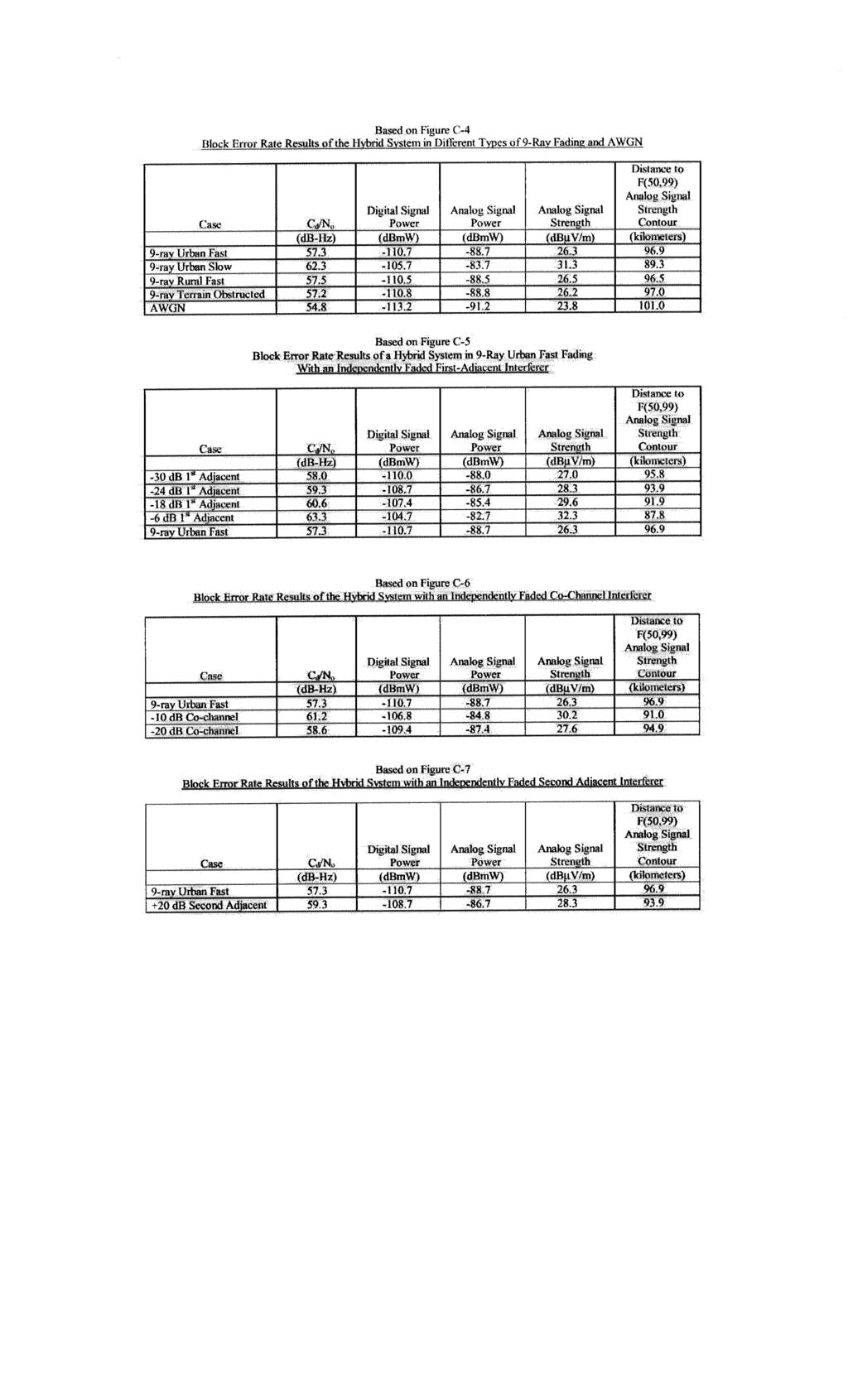
202
203 Appendix H Graphical representation of L+R and L-R for audio files TP1_DAB.wav, TP2_DAB.wav, TP3_DAB.wav

204
205
206
207 Appendix I USADR IBOC DAB to Host FM Test Report Review
208 MEMORANDUM From: T. Keller To: NRSC DAB Subcommittee EWG Date: March 10, 2000 Subject: USADR IBOC DAB to Host FM Test Report Review Appendix E, Figure 7 (in Section 5.4 of Appendix E in USADR submission - host analog compatibility in the presence of IBOC, linear channel) is a summary showing the differences in S/N ratio between analog and hybrid IBOC caused by the digital to host analog interference. This figure shows the S/N differences for three FM stereo receivers operating with a no-dab FM signal and an FM signal with DAB. The tests were conducted using three RF signal levels and 100,000 K additive white Gaussian noise. Appendix E of the report did not show the S/N reference (i.e. the actual S/N values achieved) for each receiver with 100,000 K additive white Gaussian noise, without the DAB carriers present. This reference value is important since it allows one to determine if the measurement has been taken at an operating point where listeners are likely to stay tuned-in to the radio station. (A measurement taken at a point where listeners are likely to tune out would not be useful.) To establish a no-dab FM analog receiver reference for the moderate and strong RF signal levels, the audio S/N measurements in Appendix F (Figure F-19, pg. 22, of the USADR submission) can be used. The Yamaha HTR-5130 and Philips AX1020 receivers were used for compatibility tests in both Appendices E and F. Because different automobile receivers were used (in Appendices E and F) the test data for them could not be included. The results of the no-dab receiver tests from Appendix F are shown in Table 1. To estimate the S/N with additive noise at the 47 dbm signal level a graph is used (see next page). Table 1. Audio S/N, no-dab Data from USADR report Figure F-19 AWGN 100,000 K Noise Temperature Reported S/N 74 dbu (-33 dbm) Estimated S/N 60 dbu (-47 dbm) Reported S/N 54 dbu (-53 dbm) Yamaha HTR db 36 db 31 db Philips AZ db 37 db 33 db Table 1 shows the S/N for the two receivers at three different signal levels (two reported, one estimated). It can be fairly assumed that the S/N at the moderate signal level ( 62 dbm) will be less than the 31dB and 33 db level reported by USADR at the 54 dbu (-53 dbm) RF level (for each receiver). Summary With the DAB operating at 22 dbc, and using the 62 dbm (moderate) signal level, the DAB interference did not overcome the 32 db S/N introduced by the 100,000 K noise on either receiver. At the strong signal level, 74 dbu (-47 dbm), only the Yamaha showed a 2.2 db decrease in S/N.

209
210 Appendix J Information on signal levels and noise
211 -----Original Message----- From: Robert Tywlak Sent: Tuesday, February 15, :59 PM To: Subject: Some good info on signal levels and noise David: Here is an Excel spreadsheet showing Noise levels and the theoretical minimum levels for DAB recovery. This data directly correlates with the testing I have done at USADR on a production car radio FM front end into a DAB receiver. If you have any questions please call or . Regards, Rob Tywlak Fujitsu Ten Minimum Analog level for DAB Recovery Noise 200 khz Noise 150 khz DAB carrier Noise Temp Noise Figure BW BW noise (K) (dbm) (dbm) (dbm) (dbm) Analog C/N 200 khz BW Assumptions: DAB Power: DAB Carrier: Min C/N DAB: Carrier spacing: -25 db / Side -48 db / carrier 3 db 350 Hz Notes: These numbers are based on total DAB power of 22 db (-25 db per side) and are theoretical limits. Margin for DAB recovery is assumed to be 3 db DAB C/N in a 350 Hz carrier bandwidth. The minimum host analog C/N value for DAB recover is db. A very good receiver with a 10 db noise figure can work down to 3000K noise environment. A production auto FM front end was tested at USADR and recovered DAB at 88 dbm host analog input. The radio had an 11 db noise figure which closely matches the theoretical limit within 1 db.
212 Appendix K Signals and noise in rural areas
![-----Original Message----- From: Robert Tywlak [mailto:rtywlak@mio.ten.fujitsu.com] Sent: Wednesday, February 16, 2000 10:15 AM To: 'dlayer@nab.](/docs-images/82/84964099/images/213-0.jpg "org' Subject: Some more info for the EWG Group David: Here is another file with actual measured signal levels in the field. Please forward to the EWG members.")
213 -----Original Message----- From: Robert Tywlak Sent: Wednesday, February 16, :15 AM To: Subject: Some more info for the EWG Group David: Here is another file with actual measured signal levels in the field. Please forward to the EWG members. If you have any questions please contact me. Regards, Rob Tywlak Fujitsu Ten Signals & Noise in Rural Areas By Robert Tywlak - Fujitsu Ten, Plymouth Michigan Note: All signals were measured with a ¼ wave magnetic mount antenna on the roof of a Chevy Malibu which was connected to the spectrum analyzer. A Garmin Street Pilot was used for GPS Readings and turned off during the measurement. All waveforms are a rolling 32 sweep average while driving to eliminate peaks and valleys in signal levels. Peak mode was used on the analyzer and actual wideband signal levels of the Analog FM station are 6 db higher than shown. The Spectrum Analyzer used was a Tektronix 2712 and has a 13 db Noise Figure. These levels are typical of what a car radio will see at the input. Glass type antennas are typically 4-6 db lower output than pole types. Photo Taken at 43:02:10N, 83:04:20W FM WDMK 35 Miles Away FM WIOG 49 Miles Away (86KW@244m) FM WGRT 30 Miles Away FM WRXF 7 Miles Away Noise Floor in 150 khz BW is below -110 dbm Noise on Graph is 6 db high due to Vehicle Noise IBOC Reception is possible on and Both would Require FAC, would Require Significant rejection of BEFORE FAC is applied because WIQB is -22 db. Actual Signal level is 6 db higher due to 9khz RBW used for station separation.
 All 3 Stations are IBOC possible due to actual Noise Floor of below -110 dbm in a 150 khz Bandwidth (Noise shown is 6 db high due to Vehicle Noise) 97.")
 94.7 WCSX is 34 Miles Away (13.5kW@290m) 94.9 WMMQ is 41 Miles Away (50kW@150m) 95.")
214 Photo Taken at 43:02:10N, 83:04:20W 97.9 WJLB is 44 Miles Away (Class B Station) WTGV is 27 Miles Away (Class A Station) 98.1 WKCQ is 50 Miles Away (Class B Station) All 3 Stations are IBOC possible due to actual Noise Floor of below -110 dbm in a 150 khz Bandwidth (Noise shown is 6 db high due to Vehicle Noise) 97.9 would require significant FAC to recover IBOC a system without it will fail completely. Actual Signal level is 6 db higher due to 9kHz RBW used for station separation. Photo Taken at 42:40:11N, 83:45:33W 94.5 WCEN is 84 Miles Away (100kW@299m) 94.7 WCSX is 34 Miles Away (13.5kW@290m) 94.9 WMMQ is 41 Miles Away (50kW@150m) 95.1 WFBE is 25 Miles Away (50kW@74m) IBOC is Possible on 94.7, 95.1, and and 94.9 would need FAC on Both sides A system without FAC would Fail completely. Noise Floor is about -110 dbm in 150 khz BW. (Noise is 6 db high due to Vehicle Noise)
215 Appendix L AM compatibility results USADR AM IBOC system
216 Lower 2nd adjacent channel interferers DHL 3/22/00 11:19 AM DELCO RECEIVER FORD RECEIVER Change in SNR (db) dbm dbm dbm D/U ratio (db) Change in SNR (db) dbm -62 dbm -77 dbm D/U ratio (db) PIONEER RECEIVER PANASONIC RECEIVER Change in SNR (db) dbm -62 dbm -77 dbm Change in SNR (db) dbm -62 dbm -77 dbm D/U ratio (db) D/U ratio (db) SONY RECEIVER Change in SNR (db) dbm -62 dbm -77 dbm D/U ratio (db)
217 Lower 1st adjacent channel interferers DHL 3/22/00 11:19 AM DELCO RECEIVER FORD RECEIVER Change in SNR (db) dbm -62 dbm -77 dbm Change in SNR (db) dbm -62 dbm -77 dbm D/U ratio (db) D/U ratio (db) PIONEER RECEIVER PANASONIC RECEIVER Change in SNR (db) dbm -62 dbm -77 dbm Change in SNR (db) dbm -62 dbm -77 dbm D/U ratio (db) D/U ratio (db) SONY RECEIVER 0 Change in SNR (db) D/U ratio (db) -47 dbm -62 dbm -77 dbm
218 Co-channel interferers DHL 3/22/00 11:19 AM DELCO RECEIVER FORD RECEIVER Change in SNR (db) D/U ratio (db) -47 dbm -62 dbm -77 dbm Change in SNR (db) D/U ratio (db) -47 dbm -62 dbm -77 dbm PIONEER RECEIVER PANASONIC RECEIVER Change in SNR (db) dbm -62 dbm -77 dbm Change in SNR (db) dbm -62 dbm -77 dbm D/U ratio (db) D/U ratio (db) SONY RECEIVER 0 Change in SNR (db) dbm -62 dbm -77 dbm D/U ratio (db)
219 Simultaneous lower and upper 1st-adjacent channel interferers DHL 3/22/00 11:19 AM DELCO RECEIVER FORD RECEIVER 0 0 Change in SNR (db) D/U ratio (db) -47 dbm -62 dbm -77 dbm Change in SNR (db) D/U ratio (db) -47 dbm -62 dbm -77 dbm PIONEER RECEIVER PANASONIC RECEIVER Change in SNR (db) D/U ratio (db) -47 dbm -62 dbm -77 dbm Change in SNR (db) D/U ratio (db) -47 dbm -62 dbm -77 dbm (Note: no results presented for -77 dbm case due to equipment problems) SONY RECEIVER Change in SNR (db) dbm -62 dbm dbm D/U ratio (db)
220 Simultaneous lower 1st- and co-channel interferers DHL 3/22/00 11:19 AM DELCO RECEIVER FORD RECEIVER Change in SNR (db) dbm -62 dbm -77 dbm / / / / 36 (Lower 1st adj.) / (co-channel) D/U ratio (db) Change in SNR (db) dbm -62 dbm -77 dbm / / / / 36 (Lower 1st adj.) / (co-channel) D/U ratio (db) PIONEER RECEIVER PANASONIC RECEIVER Change in SNR (db) / / / / dbm -62 dbm -77 dbm (Lower 1st adj.) / (co-channel) D/U ratio (db) Change in SNR (db) dbm dbm dbm / / / / 36 (Lower 1st adj.) / (co-channel) D/U ratio (db) SONY RECEIVER Change in SNR (db) / / / / dbm -62 dbm -77 dbm (Lower 1st adj.) / (co-channel) D/U ratio (db) (Note: no results presented for -77 dbm case due to equipment problems)
221 Appendix M USADR comments on this evaluation report
222
223 NRSC-R53 NRSC Document Improvement Proposal If in the review or use of this document a potential change appears needed for safety, health or technical reasons, please fill in the appropriate information below and , mail or fax to: National Radio Systems Committee c/o Consumer Electronics Association Technology & Standards Department 1919 S. Eads St. Arlington, VA FAX: standards@ce.org DOCUMENT NO. DOCUMENT TITLE: SUBMITTER S NAME: COMPANY: TEL: FAX: ADDRESS: URGENCY OF CHANGE: Immediate At next revision PROBLEM AREA (ATTACH ADDITIONAL SHEETS IF NECESSARY): a. Clause Number and/or Drawing: b. Recommended Changes: c. Reason/Rationale for Recommendation: ADDITIONAL REMARKS: SIGNATURE: DATE: Date forwarded to NAB S&T: Responsible Committee: Co-chairmen: Date forwarded to co-chairmen: FOR NRSC USE ONLY


224
NATIONAL RADIO SYSTEMS COMMITTEE
 NRSC REPORT NATIONAL RADIO SYSTEMS COMMITTEE NRSC-R54 Evaluation of LDR's Submission to the NRSC DAB Subcommittee of Selected Laboratory and Field Test Results for its FM and AM Band IBOC System April
NATIONAL RADIO SYSTEMS COMMITTEE
 NRSC GUIDELINE NATIONAL RADIO SYSTEMS COMMITTEE NRSC-G202-A FM IBOC Total Digital Sideband Power for Various Configurations April 2016 NAB: 1771 N Street, N.W. 1919 South Eads Street Washington, DC 20036
NATIONAL RADIO SYSTEMS COMMITTEE
 NRSC STANDARD NATIONAL RADIO SYSTEMS COMMITTEE NRSC-2-A Emission Limitation for Analog AM Broadcast Transmission September, 2007 NAB: 1771 N Street, N.W. CEA: 1919 South Eads Street Washington, DC 20036
Adjacent Channel Studies in the FM Band
 Adjacent Channel Studies in the FM Band Prepared for the NRSC By ibiquity Digital Corporation 11/09/00 Adjacent Channel Studies in the FM Band Page 1 As part of its AM IBOC development effort, ibiquity
NRSC-2 Emission Limitation for AM Broadcast Transmission June, 1988
 NRSC-2 Emission Limitation for AM Broadcast Transmission June, 1988 NOTICE NRSC Standards, Bulletins and other technical publications are designed to serve the public interest through eliminating misunderstandings
Appendix L. AM Hybrid IBOC DAB Field Test Results
 Appendix L AM Hybrid IBOC DAB Field Test Results 1. Overview The USADR AM IBOC DAB system has been carefully designed to provide superior digital audio performance while minimizing the impact to existing
CEA Standard. BTSC System Multichannel Television Sound Recommended Practices CEA-TVSB-5 S-2015
 CEA Standard BTSC System Multichannel Television Sound Recommended Practices CEA-TVSB-5 S-2015 July 1985 NOTICE Consumer Electronics Association (CEA ) Standards, Bulletins and other technical publications
HD Radio FM Transmission. System Specifications
 HD Radio FM Transmission System Specifications Rev. G December 14, 2016 SY_SSS_1026s TRADEMARKS HD Radio and the HD, HD Radio, and Arc logos are proprietary trademarks of ibiquity Digital Corporation.
HD Radio AM Transmission System Specifications Rev. F August 24, 2011
 HD Radio AM Transmission System Specifications Rev. F August 24, 2011 SY_SSS_1082s TRADEMARKS HD Radio and the HD, HD Radio, and Arc logos are proprietary trademarks of ibiquity Digital Corporation. ibiquity,
NOTICE. (Formulated under the cognizance of the CTA R7 Home Networks Committee.)
") ANSI/CTA Standard Control Network Power Line (PL) Channel Specification ANSI/CTA-709.2 S-2017 June 2000 NOTICE Consumer Technology Association (CTA) Standards, Bulletins and other technical publications
ANSI/CTA Standard Control Network Power Line (PL) Channel Specification ANSI/CTA-709.2 S-2017 June 2000 NOTICE Consumer Technology Association (CTA) Standards, Bulletins and other technical publications
Interleaving IBOC Signals for a Digital HD Radio Multiplex
 Interleaving IBOC Signals for a Digital HD Radio Multiplex A Transition Strategy to All Digital HD Radio Broadcasting Philipp Schmid October 14, 2015 Overview Introduction Hybrid IBOC Signal Overview All
ECC Report 141 Technical supplement. TECHNICAL SUPPLEMENT TO ECC REPORT 141 FUTURE POSSIBILITIES FOR THE DIGITALISATION OF BAND II (87.
 ECC Report 141 Technical supplement TECHNICAL SUPPLEMENT TO ECC REPORT 141 FUTURE POSSIBILITIES FOR THE DIGITALISATION OF BAND II (87.5-108 MHz) April 2012 Technical supplement to ECC REPORT 141 Page 2
NOTICE. (Formulated under the cognizance of the CTA R4 Video Systems Committee.)
") CTA Bulletin Mobile/Handheld DTV Implementation Guidelines CTA-CEB26-B (Formerly CEA-CEB26-B) November 2014 NOTICE Consumer Technology Association (CTA) Standards, Bulletins and other technical publications
CTA Bulletin Mobile/Handheld DTV Implementation Guidelines CTA-CEB26-B (Formerly CEA-CEB26-B) November 2014 NOTICE Consumer Technology Association (CTA) Standards, Bulletins and other technical publications
IBOC Coverage and Interference
 IBOC Coverage and Interference Presented at NAB Radio & Broadcasters Clinic, Fall 2006 Introduction, we will look at HD coverage and the impact on analog coverage caused by HD interference. 1 IBOC Coverage
HD Radio FM Transmission System Specifications
 HD Radio FM Transmission System Specifications Rev. D February 18, 2005 Doc. No. SY_SSS_1026s TRADEMARKS The ibiquity Digital logo and ibiquity Digital are registered trademarks of ibiquity Digital Corporation.
NOTICE. (Formulated under the cognizance of the CTA R4 Video Systems Committee.)
") ANSI/CTA Standard TV Receiving Antenna Performance Presentation Measurement ANSI/CTA-774-C (Formerly ANSI/) November 2014 NOTICE Consumer Technology Association (CTA) Standards, Bulletins and other technical
ANSI/CTA Standard TV Receiving Antenna Performance Presentation Measurement ANSI/CTA-774-C (Formerly ANSI/) November 2014 NOTICE Consumer Technology Association (CTA) Standards, Bulletins and other technical
NXDN Signal and Interference Contour Requirements An Empirical Study
 NXDN Signal and Interference Contour Requirements An Empirical Study Icom America Engineering December 2007 Contents Introduction Results Analysis Appendix A. Test Equipment Appendix B. Test Methodology
NOTICE. (Formulated under the cognizance of the CTA R4 Video Systems Committee.)
") ANSI/CTA Standard Antenna Control Interface ANSI/CTA-909-B (Formerly ANSI/) January 2011 NOTICE Consumer Technology Association (CTA) Standards, Bulletins and other technical publications are designed
ANSI/CTA Standard Antenna Control Interface ANSI/CTA-909-B (Formerly ANSI/) January 2011 NOTICE Consumer Technology Association (CTA) Standards, Bulletins and other technical publications are designed
Before the FEDERAL COMMUNICATIONS COMMISSION Washington, D.C
 Before the FEDERAL COMMUNICATIONS COMMISSION Washington, D.C. 20554 In the Matter of ) ) Digital Audio Broadcasting Systems ) MM Docket No. 99-325 And Their Impact On the Terrestrial Radio ) Broadcast
COMPATIBILITY AND SHARING ANALYSIS BETWEEN DVB T AND TALKBACK LINKS IN BANDS IV AND V
 European Radiocommunications Committee (ERC) within the European Conference of Postal and Telecommunications Administrations (CEPT) COMPATIBILITY AND SHARING ANALYSIS BETWEEN DVB T AND TALKBACK LINKS IN
NOTICE. (Formulated under the cognizance of the CTA R6 Portable, Handheld and In-Vehicle Electronics Committee.)
") ANSI/CTA Standard Testing and Measurement Methods for Mobile Loudspeaker Systems ANSI/CTA-2031 R-2014 (Formerly ANSI/CEA-2031 R-2014) September 2008 NOTICE Consumer Technology Association (CTA) Standards,
ANSI/CTA Standard Testing and Measurement Methods for Mobile Loudspeaker Systems ANSI/CTA-2031 R-2014 (Formerly ANSI/CEA-2031 R-2014) September 2008 NOTICE Consumer Technology Association (CTA) Standards,
EIA STANDARD TP-95. Full Mating and Mating Stability Test Procedure for Electrical Connectors EIA/ECA EIA
 EIA STANDARD ANSI/EIA-364-95-1999(R2006) Approved: April 14, 1999 Reaffirmed: March 31, 2006 TP-95 EIA-364-95 Full Mating and Mating Stability Test Procedure for Electrical Connectors EIA/ECA-364-95 APRIL
1 Minimum usable field strength
 1 RECOMMENDATION ITU-R BS.412-8* PLANNING STANDARDS FOR FM SOUND BROADCASTING AT VHF (Questions ITU-R 74/1 and ITU-R 11/1) (1956-1959-1963-1974-1978-1982-1986-199-1994-1995-1998) The ITU Radiocommunication
AMERICAN NATIONAL STANDARD
 Interface Practices Subcommittee AMERICAN NATIONAL STANDARD Measurement Procedure for Noise Power Ratio NOTICE The Society of Cable Telecommunications Engineers (SCTE) / International Society of Broadband
RECOMMENDATION ITU-R BS *, ** System for automatic tuning and other applications in FM radio receivers for use with the pilot-tone system
 Rec. ITU-R BS.643-2 1 RECOMMENDATION ITU-R BS.643-2 *, ** System for automatic tuning and other applications in FM radio receivers for use with the pilot-tone system The ITU Radiocommunication Assembly,
RECOMMENDATION ITU-R BS
 Rec. ITU-R BS.1194-1 1 RECOMMENDATION ITU-R BS.1194-1 SYSTEM FOR MULTIPLEXING FREQUENCY MODULATION (FM) SOUND BROADCASTS WITH A SUB-CARRIER DATA CHANNEL HAVING A RELATIVELY LARGE TRANSMISSION CAPACITY
RECOMMENDATION ITU-R BT.655-7
 Rec. ITU-R BT.655-7 1 RECOMMENDATION ITU-R BT.655-7 Radio-frequency protection ratios for AM vestigial sideband terrestrial television systems interfered with by unwanted analogue vision signals and their
Shively Labs. Spectral Regrowth
 Shively Labs Spectral Regrowth Abstract Intermodulation products, or spurs, can develop within the analog and digital transmitters in combined systems using high-level injection. In some cases, spurs can
The meaning of planning margins in a post-rrc-06 situation
 - 1 - Document INFO/5-E The meaning of planning margins in a post-rrc-06 situation 1. Introduction As a result of decisions taken during the RRC-04 the concept of margins was introduced in order to simplify
Technical Requirements for Land Mobile and Fixed Radio Services Operating in the Bands MHz and MHz
 Provisional - Issue 1 March 2004 Spectrum Management and Telecommunications Policy Standard Radio System Plans Technical Requirements for Land Mobile and Fixed Radio Services Operating in the Bands 138-144
FM-IBOC Broadcast Systems Architecture Considerations for Single Frequency Networks
 FM-IBOC Broadcast Systems Architecture Considerations for Single Frequency Networks Philipp Schmid Nautel Limited April 19th, 2009 Presentation Outline Introduction KCSN case study Need for Hybrid FM+IBOC
Spectrum Utilization Policy Decisions for the Band MHz
 December 2012 Spectrum Management and Telecommunications Spectrum Utilization Policy Decisions for the Band 1435-1525 MHz Aussi disponible en français PS 1435 MHz Contents 1. Intent... 1 2. Background...
ENGINEERING COMMITTEE Interface Practices Subcommittee AMERICAN NATIONAL STANDARD ANSI/SCTE Measurement Procedure for Noise Power Ratio
 ENGINEERING COMMITTEE Interface Practices Subcommittee AMERICAN NATIONAL STANDARD ANSI/SCTE 119 2006 Measurement Procedure for Noise Power Ratio NOTICE The Society of Cable Telecommunications Engineers
EIA STANDARD TP-27B. Mechanical Shock (Specified Pulse) Test Procedure for Electrical Connectors EIA B ELECTRONIC INDUSTRIES ASSOCIATION
 Test Procedure for Electrical Connectors EIA B ELECTRONIC INDUSTRIES ASSOCIATION") ANSI/-1996 Approved: April 17, 1996 EIA STANDARD TP-27B Mechanical Shock (Specified Pulse) Test Procedure for Electrical Connectors (Revision of EIA-364-27A) MAY 1996 ELECTRONIC INDUSTRIES ASSOCIATION
ANSI/-1996 Approved: April 17, 1996 EIA STANDARD TP-27B Mechanical Shock (Specified Pulse) Test Procedure for Electrical Connectors (Revision of EIA-364-27A) MAY 1996 ELECTRONIC INDUSTRIES ASSOCIATION
UPDATES to the. Rules of Procedure. (Edition of 1998) approved by the Radio Regulations Board. Contents
 approved by the Radio Regulations Board. Contents") UPDATES to the Rules of Procedure (Edition of 1998) approved by the Radio Regulations Board Revision (1) (Circular No.) Date Part ARS Pages to be removed Pages to be inserted 1 June 1999 A1 ARS5 15-18
UPDATES to the Rules of Procedure (Edition of 1998) approved by the Radio Regulations Board Revision (1) (Circular No.) Date Part ARS Pages to be removed Pages to be inserted 1 June 1999 A1 ARS5 15-18
DVB-T2 (T2) MISO versus SISO Field Test
 MISO versus SISO Field Test") DVB-T2 (T2) MISO versus SISO Field Test Author: Bjørn Skog, M.Sc. E-mail: bjorn.skog@telenor.com Company: Telenor Broadcast, Norkring AS, Norway July 3rd 2013 @ LS telcom Summit 2013 V.2 2.7.13 The Case
DVB-T2 (T2) MISO versus SISO Field Test Author: Bjørn Skog, M.Sc. E-mail: bjorn.skog@telenor.com Company: Telenor Broadcast, Norkring AS, Norway July 3rd 2013 @ LS telcom Summit 2013 V.2 2.7.13 The Case
Provided by: Radio Systems, Inc. 601 Heron Drive Bridgeport, NJ
 Provided by: Radio Systems, Inc. 601 Heron Drive Bridgeport, NJ 08014 856-467-8000 www.radiosystems.com Before the Federal Communications Commission Washington, DC 20554 GEN Docket No. 87-839 In the Matter
Introduction. TV Coverage and Interference, February 06, 2004.
 A New Prediction Model for M/H Mobile DTV Service Prepared for OMVC June 28, 2011 Charles Cooper, du Treil, Lundin & Rackley, Inc. Victor Tawil, National Association of Broadcasters Introduction The Open
NOTICE. (Formulated under the cognizance of the CTA R6 Portable, Handheld and In-Vehicle Electronics Committee.)
") ANSI/CTA Standard Performance Specification for Public Alert Receivers ANSI/CTA-2009-B R-2016 (Formerly ANSI/CEA-2009-B) November 2010 NOTICE Consumer Technology Association (CTA) Standards, Bulletins
ANSI/CTA Standard Performance Specification for Public Alert Receivers ANSI/CTA-2009-B R-2016 (Formerly ANSI/CEA-2009-B) November 2010 NOTICE Consumer Technology Association (CTA) Standards, Bulletins
NATIONAL RADIO SYSTEMS COMMITTEE
 NRSC REPORT NATIONAL RADIO SYSTEMS COMMITTEE NRSC-R55 EIA/NRSC DAR Systems Subjective Tests of Audio Quality and Transmission Impairments Final Report July 21, 1995 NAB: 1771 N Street, N.W. CEA: 1919 South
Technical Annex. This criterion corresponds to the aggregate interference from a co-primary allocation for month.
 RKF Engineering Solutions, LLC 1229 19 th St. NW, Washington, DC 20036 Phone 202.463.1567 Fax 202.463.0344 www.rkf-eng.com 1. Protection of In-band FSS Earth Stations Technical Annex 1.1 In-band Interference
Balancing Bandwidth and Bytes: Managing storage and transmission across a datacast network
 Balancing Bandwidth and Bytes: Managing storage and transmission across a datacast network Pete Ludé iblast, Inc. Dan Radke HD+ Associates 1. Introduction The conversion of the nation s broadcast television
An Engineering Statement Prepared on Behalf of the National Association of Broadcasters
 An Engineering Statement Prepared on Behalf of the National Association of Broadcasters Regarding the Technical Aspects of the SDARS Providers XM and Sirius March 16, 2007 Prepared By: Dennis Wallace Meintel,
NAB WRITTEN SUBMISSION TO ICASA ON DIGITAL SOUND BROADCASTING DISCUSSION DOCUMENT 6 JUNE 2018
 NAB WRITTEN SUBMISSION TO ICASA ON DIGITAL SOUND BROADCASTING DISCUSSION DOCUMENT 6 JUNE 2018 Postal Address: P.O.Box 412363, Craighall, 2024, South Africa Tel: +27(11) 326 2444 Fax: +27(11) 326 3086 info@nabsa.co.za
Electronic Communications Committee (ECC) within the European Conference of Postal and Telecommunications Administrations (CEPT)
 within the European Conference of Postal and Telecommunications Administrations (CEPT)") Electronic Communications Committee (ECC) within the European Conference of Postal and Telecommunications Administrations (CEPT) THE POSSIBILITIES AND CONSEQUENCES OF CONVERTING GE06 DVB-T ALLOTMENTS/ASSIGNMENTS
Electronic Communications Committee (ECC) within the European Conference of Postal and Telecommunications Administrations (CEPT) THE POSSIBILITIES AND CONSEQUENCES OF CONVERTING GE06 DVB-T ALLOTMENTS/ASSIGNMENTS
Design for Analog SFN. Chuck Kelly - Nautel Hans Van Zuphen Thimeo / Telos Alliance Geoff Steadman Telos Alliance
 Design for Analog SFN Chuck Kelly - Nautel Hans Van Zuphen Thimeo / Telos Alliance Geoff Steadman Telos Alliance Presentation Overview 1. FM Analog Single Frequency Networks Basics 2. System metrics 3.
Chapter 2 Channel Equalization
 Chapter 2 Channel Equalization 2.1 Introduction In wireless communication systems signal experiences distortion due to fading [17]. As signal propagates, it follows multiple paths between transmitter and
RESEARCH ON METHODS FOR ANALYZING AND PROCESSING SIGNALS USED BY INTERCEPTION SYSTEMS WITH SPECIAL APPLICATIONS
 Abstract of Doctorate Thesis RESEARCH ON METHODS FOR ANALYZING AND PROCESSING SIGNALS USED BY INTERCEPTION SYSTEMS WITH SPECIAL APPLICATIONS PhD Coordinator: Prof. Dr. Eng. Radu MUNTEANU Author: Radu MITRAN
FM HD Radio. Field Performance. With. Unequal Digital Sideband Carrier Levels. (Preliminary) ibiquity Digital Corporation
 ibiquity Digital Corporation") FM HD Radio Field Performance With Unequal Sideband Carrier Levels (Preliminary) Revision 01.03 February 22, 2011 ibiquity Corporation 6711 Columbia Gateway Drive Suite 500 Columbia, Maryland 21046 (443)
FM HD Radio Field Performance With Unequal Sideband Carrier Levels (Preliminary) Revision 01.03 February 22, 2011 ibiquity Corporation 6711 Columbia Gateway Drive Suite 500 Columbia, Maryland 21046 (443)
RECOMMENDATION ITU-R S.1063 * Criteria for sharing between BSS feeder links and other Earth-to-space or space-to-earth links of the FSS
 Rec. ITU-R S.1063 1 RECOMMENDATION ITU-R S.1063 * Criteria for sharing between BSS feeder links and other Earth-to-space or space-to-earth links of the FSS (Question ITU-R 10/) (199) The ITU Radiocommunication
Design concepts for a Wideband HF ALE capability
 Design concepts for a Wideband HF ALE capability W.N. Furman, E. Koski, J.W. Nieto harris.com THIS INFORMATION WAS APPROVED FOR PUBLISHING PER THE ITAR AS FUNDAMENTAL RESEARCH Presentation overview Background
A1.1 Coverage levels in trial areas compared to coverage levels throughout UK
 Annex 1 A1.1 Coverage levels in trial areas compared to coverage levels throughout UK To determine how representative the coverage in the trial areas is of UK coverage as a whole, a dataset containing
DTT COVERAGE PREDICTIONS AND MEASUREMENT
 DTT COVERAGE PREDICTIONS AND MEASUREMENT I. R. Pullen Introduction Digital terrestrial television services began in the UK in November 1998. Unlike previous analogue services, the planning of digital television
From the Transmitter Site
 The Broadcasters Desktop Resource www.thebdr.net edited by Barry Mishkind the Eclectic Engineer From the Transmitter Site Understanding AM NRSC Measurements By James Boyd [January 2013] The FCC requires
EXTENDING YOUR HD RADIO FOOTPRINT
 EXTENDING YOUR HD RADIO FOOTPRINT Geoffrey N. Mendenhall, P.E. Vice President Transmission Research and Technology Harris Corporation, Broadcast Communication Division Mason, Ohio PURPOSE: The purpose
Before the Federal Communications Commission Washington, D.C ) ) ) ) ) REPORT AND ORDER. Adopted: February 22, 2011 Released: March 4, 2011
 ) ) ) ) REPORT AND ORDER. Adopted: February 22, 2011 Released: March 4, 2011") Before the Federal Communications Commission Washington, D.C. 20554 In the Matter of Amendment of the Amateur Service Rules to Facilitate Use of Spread Spectrum Communications Technologies WT Docket No.
Before the Federal Communications Commission Washington, D.C. 20554 In the Matter of Amendment of the Amateur Service Rules to Facilitate Use of Spread Spectrum Communications Technologies WT Docket No.
Practical Principle and Technical Standards for FM Planning
 Practical Principle and Technical Standards for FM Planning NBTC Thailand 11.05.2015 FM Planning Methodology The following methodology has been undertaken to repack and provide new spectrum for FM Community
ADJACENT BAND COMPATIBILITY OF TETRA AND TETRAPOL IN THE MHZ FREQUENCY RANGE, AN ANALYSIS COMPLETED USING A MONTE CARLO BASED SIMULATION TOOL
 European Radiocommunications Committee (ERC) within the European Conference of Postal and Telecommunications Administrations (CEPT) ADJACENT BAND COMPATIBILITY OF TETRA AND TETRAPOL IN THE 380-400 MHZ
Method of measuring the maximum frequency deviation of FM broadcast emissions at monitoring stations. Recommendation ITU-R SM.
 Recommendation ITU-R SM.1268-4 (11/217) Method of measuring the maximum frequency deviation of FM broadcast emissions at monitoring stations SM Series Spectrum management ii Rec. ITU-R SM.1268-4 Foreword
Submission by Free TV Limited
 Submission by Free TV Limited Australian Communications and Media Authority Amendments to the Technical Planning Guidelines for the planning of individual services that use the Broadcasting Services Bands
Non-Data Aided Doppler Shift Estimation for Underwater Acoustic Communication
 Non-Data Aided Doppler Shift Estimation for Underwater Acoustic Communication (Invited paper) Paul Cotae (Corresponding author) 1,*, Suresh Regmi 1, Ira S. Moskowitz 2 1 University of the District of Columbia,
ENGINEERING COMMITTEE Interface Practices Subcommittee AMERICAN NATIONAL STANDARD ANSI/SCTE
 ENGINEERING COMMITTEE Interface Practices Subcommittee AMERICAN NATIONAL STANDARD ANSI/SCTE 115 2011 Test Method for Reverse Path (Upstream) Intermodulation Using Two Carriers NOTICE The Society of Cable
RECOMMENDATION ITU-R BS System for digital sound broadcasting in the broadcasting bands below 30 MHz
 Rec. ITU-R BS.1514 1 RECOMMENDATION ITU-R BS.1514 System for digital sound broadcasting in the broadcasting bands below 30 MHz (Question ITU-R 217/10) (2001) The ITU Radiocommunication Assembly, considering
AIRAURAX1 Digital Audio Spectral Processor
 AIRAURAX1 Digital Audio Spectral Processor BROADCAST AUDIO PERFECTIONISTS 1 the front panel and what s behind it wide touchscreen displays give you new ways to control your awesome sound AirAura X1 brings
Antennas and Propagation
 CMPE 477 Wireless and Mobile Networks Lecture 3: Antennas and Propagation Antennas Propagation Modes Line of Sight Transmission Fading in the Mobile Environment Introduction An antenna is an electrical
ENGINEERING COMMITTEE
 ENGINEERING COMMITTEE Interface Practices Subcommittee AMERICAN NATIONAL STANDARD ANSI/SCTE 45 2012 Test Method for Group Delay NOTICE The Society of Cable Telecommunications Engineers (SCTE) Standards
Coordination Policy. Version 1.0 Approved: 18-November-2017
 Coordination Policy Version 1.0 Approved: 18-November-2017 With thanks and appreciation to the officers and staff of: Illinois Repeater Association, Inc. Wisconsin Association of Repeaters, Inc. Michigan
Application of a Telemetry System using DSB-AM Sub-Carriers
 Application of a Telemetry System using DSB-AM Sub-Carriers Item Type text; Proceedings Authors Roche, A. O. Publisher International Foundation for Telemetering Journal International Telemetering Conference
Urban WiMAX response to Ofcom s Spectrum Commons Classes for licence exemption consultation
 Urban WiMAX response to Ofcom s Spectrum Commons Classes for licence exemption consultation July 2008 Urban WiMAX welcomes the opportunity to respond to this consultation on Spectrum Commons Classes for
Digital Radio Mondiale RESULTS OF THE DRM FIELD TRIAL IN SRI LANKA
 Radiocommunication Study Groups Received: 29 April 2011 Reference: Annex 6 to Document 6A/454 Document 2 May 2011 English only Digital Radio Mondiale RESULTS OF THE DRM FIELD TRIAL IN SRI LANKA Introduction
FM Transmission Systems Course
 FM Transmission Systems Course Course Description An FM transmission system, at its most basic level, consists of the transmitter, the transmission line and antenna. There are many variables within these
Part 9: Application Procedures and Rules for Terrestrial S-DARS Undertakings (Satellite Digital Audio Radio Service)
") Issue 2 January 2009 Spectrum Management and Telecommunications Broadcasting Procedures and Rules Part 9: Application Procedures and Rules for Terrestrial S-DARS Undertakings (Satellite Digital Audio Radio
Issue 2 January 2009 Spectrum Management and Telecommunications Broadcasting Procedures and Rules Part 9: Application Procedures and Rules for Terrestrial S-DARS Undertakings (Satellite Digital Audio Radio
Antennas & Propagation. CSG 250 Fall 2007 Rajmohan Rajaraman
 Antennas & Propagation CSG 250 Fall 2007 Rajmohan Rajaraman Introduction An antenna is an electrical conductor or system of conductors o Transmission - radiates electromagnetic energy into space o Reception
Method of measuring the maximum frequency deviation of FM broadcast emissions at monitoring stations
 Recommendation ITU-R SM.1268-2 (02/2011) Method of measuring the maximum frequency deviation of FM broadcast emissions at monitoring stations SM Series Spectrum management ii Rec. ITU-R SM.1268-2 Foreword
Carrier Frequency Offset Estimation Algorithm in the Presence of I/Q Imbalance in OFDM Systems
 Carrier Frequency Offset Estimation Algorithm in the Presence of I/Q Imbalance in OFDM Systems K. Jagan Mohan, K. Suresh & J. Durga Rao Dept. of E.C.E, Chaitanya Engineering College, Vishakapatnam, India
Table 1: OoB e.i.r.p. limits for the MFCN SDL base station operating in the band MHz
 ECC Report 202 Out-of-Band emission limits for Mobile/Fixed Communication Networks (MFCN) Supplemental Downlink (SDL) operating in the 1452-1492 MHz band September 2013 ECC REPORT 202- Page 2 0 EXECUTIVE
2 meter refarming proposal. Uniform 15 khz proposal
 2 meter refarming proposal Uniform 15 khz proposal Overview The submitters of this proposal would strongly prefer not to change the current 20 khz channel spacing used in the NARCC area 145 MHz repeater
International Journal of Engineering and Technology Volume 3 No. 6, June, 2013
 International Journal of Engineering and Technology Volume 3 No. 6, June, 2013 Spectrum Compatibility Study of Terrestrial Digital Audio Broadcasting System and the Microwave Radio Relay Links in the L-Band
FUJITSU TEN's Approach to Digital Broadcasting
 FUJITSU TEN's Approach to Digital Broadcasting Mitsuru Sasaki Kazuo Takayama 1. Introduction There has been a notable increase recently in the number of television commercials advertising television sets
RECOMMENDATION ITU-R SA Protection criteria for deep-space research
 Rec. ITU-R SA.1157-1 1 RECOMMENDATION ITU-R SA.1157-1 Protection criteria for deep-space research (1995-2006) Scope This Recommendation specifies the protection criteria needed to success fully control,
Qualcomm Research DC-HSUPA
 Qualcomm, Technologies, Inc. Qualcomm Research DC-HSUPA February 2015 Qualcomm Research is a division of Qualcomm Technologies, Inc. 1 Qualcomm Technologies, Inc. Qualcomm Technologies, Inc. 5775 Morehouse
All Digital HD HD Multiplex Field Trial at KKLZ, Las Vegas
 All Digital HD HD Multiplex Field Trial at KKLZ, Las Vegas Philipp Schmid Research Engineer at Nautel January/February 2018 Presentation Agenda All Digital Signal Configurations All Digital Service Modes
NATIONAL RADIO SYSTEMS COMMITTEE
 NRSC STANDARD NATIONAL RADIO SYSTEMS COMMITTEE NRSC-5-D In-band/on-channel Digital Radio Broadcasting Standard April, 2017 NAB: 1771 N Street, N.W. CTA: 1919 South Eads Street Washington, DC 20036 Arlington,
SAUDI ARABIAN STANDARDS ORGANIZATION (SASO) TECHNICAL DIRECTIVE PART ONE: STANDARDIZATION AND RELATED ACTIVITIES GENERAL VOCABULARY
 TECHNICAL DIRECTIVE PART ONE: STANDARDIZATION AND RELATED ACTIVITIES GENERAL VOCABULARY") SAUDI ARABIAN STANDARDS ORGANIZATION (SASO) TECHNICAL DIRECTIVE PART ONE: STANDARDIZATION AND RELATED ACTIVITIES GENERAL VOCABULARY D8-19 7-2005 FOREWORD This Part of SASO s Technical Directives is Adopted
SAUDI ARABIAN STANDARDS ORGANIZATION (SASO) TECHNICAL DIRECTIVE PART ONE: STANDARDIZATION AND RELATED ACTIVITIES GENERAL VOCABULARY D8-19 7-2005 FOREWORD This Part of SASO s Technical Directives is Adopted
Rec. ITU-R F RECOMMENDATION ITU-R F *
 Rec. ITU-R F.162-3 1 RECOMMENDATION ITU-R F.162-3 * Rec. ITU-R F.162-3 USE OF DIRECTIONAL TRANSMITTING ANTENNAS IN THE FIXED SERVICE OPERATING IN BANDS BELOW ABOUT 30 MHz (Question 150/9) (1953-1956-1966-1970-1992)
New Methods for HD Radio Crest Factor Reduction and Pre-correction
 New Methods for HD Radio Crest Factor Reduction and Pre-correction Featuring GatesAir s April 12, 2015 NAB Show 2015 Tim Anderson Radio Product & Business Development Manager Kevin Berndsen Senior Signal
RECOMMENDATION ITU-R BS
 Rec. ITU-R BS.1350-1 1 RECOMMENDATION ITU-R BS.1350-1 SYSTEMS REQUIREMENTS FOR MULTIPLEXING (FM) SOUND BROADCASTING WITH A SUB-CARRIER DATA CHANNEL HAVING A RELATIVELY LARGE TRANSMISSION CAPACITY FOR STATIONARY
C/I = log δ 3 log (i/10)
") Rec. ITU-R S.61-3 1 RECOMMENDATION ITU-R S.61-3 NECESSARY PROTECTION RATIOS FOR NARROW-BAND SINGLE CHANNEL-PER-CARRIER TRANSMISSIONS INTERFERED WITH BY ANALOGUE TELEVISION CARRIERS (Question ITU-R 50/4)
Rec. ITU-R S.61-3 1 RECOMMENDATION ITU-R S.61-3 NECESSARY PROTECTION RATIOS FOR NARROW-BAND SINGLE CHANNEL-PER-CARRIER TRANSMISSIONS INTERFERED WITH BY ANALOGUE TELEVISION CARRIERS (Question ITU-R 50/4)
AMERICAN NATIONAL STANDARD
 ENGINEERING COMMITTEE Interface Practices Subcommittee AMERICAN NATIONAL STANDARD ANSI/SCTE 151 2015 Mechanical, Electrical, and Environmental Requirements for RF Traps and Filters NOTICE The Society of
Technical Requirements for Land Mobile and Fixed Radio Services Operating in the Bands / MHz and / MHz
 Issue 5 November 2013 Spectrum Management and Telecommunications Standard Radio System Plan Technical Requirements for Land Mobile and Fixed Radio Services Operating in the Bands 806-821/851-866 MHz and
Denny & Associates, P.C. Consulting Engineers Oxon Hill, Maryland
 Denny & Associates, P.C. Consulting Engineers Oxon Hill, Maryland ENGINEERING REPORT EVALUATION OF THE USE OF SEPARATE TRANSMITTING ANTENNAS FOR IN-BAND-ON-CHANNEL DIGITAL AND ANALOG FM BROADCASTING PREPARED
BELGIAN INSTITUTE FOR POSTAL AND TELECOMMUNICATIONS
 Page 1 BELGIAN INSTITUTE FOR POSTAL AND TELECOMMUNICATIONS Feature: Decision RAM 24/04/2012 DECISION OF THE COUNCIL OF THE INSTITUTE OF 24 APRIL 2012 ON THE FREQUENCY, AND POWER TRANSMISSION MODES WHICH
Before the Federal Communications Commission Washington, D.C
 Before the Federal Communications Commission Washington, D.C. 20554 In the Matter of ) ) Proposed Changes in the Commission s ) ET Docket No. 03-137 Rules Regarding Human Exposure to ) Radiofrequency Electronic
2 GHz Licence-exempt Personal Communications Service Devices (LE-PCS)
") RSS-213 Issue 2 December 2005 Spectrum Management and Telecommunications Radio Standards Specification 2 GHz Licence-exempt Personal Communications Service Devices (LE-PCS) Aussi disponible en français
RSS-213 Issue 2 December 2005 Spectrum Management and Telecommunications Radio Standards Specification 2 GHz Licence-exempt Personal Communications Service Devices (LE-PCS) Aussi disponible en français
Comments of Shared Spectrum Company
 Before the DEPARTMENT OF COMMERCE NATIONAL TELECOMMUNICATIONS AND INFORMATION ADMINISTRATION Washington, D.C. 20230 In the Matter of ) ) Developing a Sustainable Spectrum ) Docket No. 181130999 8999 01
ERC Recommendation 54-01
 ERC Recommendation 54-01 Method of measuring the maximum frequency deviation of FM broadcast emissions in the band 87.5 to 108 MHz at monitoring stations Approved May 1998 Amended 13 February 2015 Amended
RECOMMENDATION ITU-R BS User requirements for audio coding systems for digital broadcasting
 Rec. ITU-R BS.1548-1 1 RECOMMENDATION ITU-R BS.1548-1 User requirements for audio coding systems for digital broadcasting (Question ITU-R 19/6) (2001-2002) The ITU Radiocommunication Assembly, considering
Radio Transmitters and Receivers Operating in the Land Mobile and Fixed Services in the Frequency Range MHz
 Issue 11 June 2011 Spectrum Management and Telecommunications Radio Standards Specification Radio Transmitters and Receivers Operating in the Land Mobile and Fixed Services in the Frequency Range 27.41-960
RECOMMENDATION ITU-R BT Error-correction, data framing, modulation and emission methods for digital terrestrial television broadcasting
 Rec. ITU-R BT.1306-3 1 RECOMMENDATION ITU-R BT.1306-3 Error-correction, data framing, modulation and emission methods for digital terrestrial television broadcasting (Question ITU-R 31/6) (1997-2000-2005-2006)
April 1998 doc:. IEEE /158. IEEE P Wireless LANs. WINForum Sharing Rules Requirements And Goals
 IEEE P802.11 Wireless LANs WINForum Sharing Rules Requirements And Goals Date: April 6, 1998 Source: WINForum 5 GHz Sharing Rules Development Committee (SRDC) Submitted by: Donald C. Johnson, Chairman