NATIONAL RADIO SYSTEMS COMMITTEE
|
|
|
- Joleen Gray
- 6 years ago
- Views:
Transcription


1 NRSC GUIDELINE NATIONAL RADIO SYSTEMS COMMITTEE NRSC-G202-A FM IBOC Total Digital Sideband Power for Various Configurations April 2016 NAB: 1771 N Street, N.W South Eads Street Washington, DC Arlington, VA Tel: Fax: Tel: Fax: Co-sponsored by the Consumer Technology Association and the National Association of Broadcasters
2 NRSC-G202-A NOTICE NRSC Standards, Guidelines, Reports and other technical publications are designed to serve the public interest through eliminating misunderstandings between manufacturers and purchasers, facilitating interchangeability and improvement of products, and assisting the purchaser in selecting and obtaining with minimum delay the proper product for his particular need. Existence of such Standards, Guidelines, Reports and other technical publications shall not in any respect preclude any member or nonmember of the Consumer Technology Association (CTA) or the National Association of Broadcasters (NAB) from manufacturing or selling products not conforming to such Standards, Guidelines, Reports and other technical publications, nor shall the existence of such Standards, Guidelines, Reports and other technical publications preclude their voluntary use by those other than CTA or NAB members, whether to be used either domestically or internationally. Standards, Guidelines, Reports and other technical publications are adopted by the NRSC in accordance with the NRSC patent policy. By such action, CTA and NAB do not assume any liability to any patent owner, nor do they assume any obligation whatever to parties adopting the Standard, Guideline, Report or other technical publication. This Guideline does not purport to address all safety problems associated with its use or all applicable regulatory requirements. It is the responsibility of the user of this Guideline to establish appropriate safety and health practices and to determine the applicability of regulatory limitations before its use. Published by CONSUMER TECHNOLOGY ASSOCIATION Technology & Standards Department 1919 S. Eads St. Arlington, VA NATIONAL ASSOCIATION OF BROADCASTERS Science and Technology Department 1771 N Street, NW Washington, DC CTA & NAB. All rights reserved. This document is available free of charge via the NRSC website at Republication or further distribution of this document, in whole or in part, requires prior permission of CTA or NAB. Page 1
3 NRSC-G202-A FOREWORD FM radio broadcasters in the U.S. have been authorized to transmit hybrid IBOC digital radio signals since Under the initial authorization, and for the first five years of IBOC operations, the sole (total) digital sideband power level authorized was at -20 dbc with respect to the analog FM signal. More recent FCC Orders, in 2007 and 2010, have authorized additional modes of operations and power levels, resulting in a plethora of authorized power levels depending upon the selected configuration. The purpose of this NRSC Guideline is to give broadcast engineers an easy-to-use, quick method for determining an FM IBOC station s authorized digital sideband power level based upon the station s operational configuration. This document is a companion to another NRSC Guideline, NRSC-G201-B, and in fact expands upon information contained in Annex 1 of that document. This NRSC Guideline is the work product of the IBOC Standards Development Working Group (ISDWG), a subgroup of the Digital Radio Broadcasting (DRB) Subcommittee of the NRSC. At the time of first adoption of this Guideline, the ISDWG was chaired by Dom Bordonaro, Cox Radio, and the DRB Subcommittee was co-chaired by Mike Bergman, JVC Kenwood Corporation, and Andy Laird, Journal Broadcast Group. The NRSC chairman at the time of first adoption was Milford Smith, Greater Media, Inc. The NRSC is jointly sponsored by the Consumer Technology Association and the National Association of Broadcasters. It serves as an industry-wide standards-setting body for technical aspects of terrestrial over-the-air radio broadcasting systems in the United States. Page 2
4 NRSC-G202-A CONTENTS 1 SCOPE REFERENCES NORMATIVE REFERENCES INFORMATIVE REFERENCES SYMBOLS AND ABBREVIATIONS DEFINITIONS BACKGROUND DETERMINING AUTHORIZED TOTAL DIGITAL SIDEBAND POWER EXPECTED DIGITAL SIDEBAND POWER SPECTRAL DENSITY (PSD) FOR VARIOUS CONFIGURATIONS ANNEX ANNEX 1 FCC Order DA Permitting FM stations to voluntarily increase FM hybrid digital ERP (adopted January 27, 2010) TABLES TABLE 1. SYMMETRIC (EQUAL) SIDEBANDS... 9 TABLE 2. ASYMMETRIC SIDEBANDS, SERVICE MODE MP TABLE 3. ASYMMETRIC SIDEBANDS, SERVICE MODE MP TABLE 4. ASYMMETRIC SIDEBANDS, SERVICE MODE MP TABLE 5. ASYMMETRIC SIDEBANDS, SERVICE MODE MP TABLE 6. DIGITAL SIDEBAND POWER SPECTRAL DENSITY (PSD) AND LIMIT LINE VALUES BASED ON D-A RATIO (MP1, MP2, MP3, MP11) Page 3
5 NRSC-G202-A FM IBOC TOTAL DIGITAL SIDEBAND POWER FOR VARIOUS CONFIGURATIONS 1 SCOPE This document provides a compilation of total digital sideband power levels for various hybrid and extended hybrid FM IBOC configurations. It also presents a chart relating digital sideband power levels to corresponding spectrum analyzer power spectral density (PSD) values in accordance with NRSC-G201- B. This document is intended as an aid to those who are responsible for or involved with FM IBOC facility design, operation, and compliance monitoring. 2 REFERENCES 2.1 Normative References This is an informative specification. There are no normative references. 2.2 Informative References The following references contain information that may be useful to those implementing this Guideline document. At the time of publication the editions indicated were valid. All standards are subject to revision, and users of this Guideline document are encouraged to investigate the possibility of applying the most recent editions of the standards listed below. [1] NRSC-5-C, In-band/on-channel Digital Radio Broadcasting Standard, National Radio Systems Committee, September 2011 [2] NRSC-G201-B, NRSC-5 RF Mask Compliance: Measurement Methods and Practice, National Radio Systems Committee, April 2010 [3] Code of Federal Regulations (CFR) 47, Part 73, Subpart C Digital Audio Broadcasting, Office of the Federal Register, National Archives and Records Administration [4] FCC DA , Order [Permitting FM stations to voluntarily increase FM hybrid digital ERP], Media Bureau, adopted January 27, 2010 [5] FCC 07-33, Digital Audio Broadcasting Systems and Their Impact on the Terrestrial Radio Broadcast Service, Second Report and Order, First Order on Reconsideration and Second Further Notice of Proposed Rule Making [Permitting FM stations to broadcast in extended hybrid modes], adopted March 22, 2007 [6] FCC , Digital Audio Broadcasting Systems and Their Impact on the Terrestrial Radio Broadcast Service, First Report and Order [Original IBOC authorization], adopted October 10, Symbols and abbreviations In this Guideline the following abbreviations are used: D-A ERP FCC FM IBOC Digital-to-Analog Effective Radiated Power Federal Communications Commission (U.S.) Frequency Modulation In-Band/On-Channel Page 4
6 NRSC-G202-A 2.4 Definitions In this Guideline the following definitions are used: Asymmetric sidebands Digital sideband Digital subcarrier Extended hybrid waveform Hybrid waveform RF mask Service mode Refers to an FM hybrid or extended hybrid IBOC configuration in which the upper and lower digital sidebands of the IBOC signal are at different power levels. Asymmetric sidebands are utilized when one sideband must be kept lower than the other sideband in order to protect a radio station on an adjacent frequency. The digital portion of an FM hybrid or extended hybrid IBOC signal consists of groups of digitally modulated subcarriers located on either side (in frequency) of the analog portion. These subcarriers are organized into groups called digital sidebands. There are two types of digital sidebands defined for IBOC signals, primary and secondary, however hybrid and extended hybrid IBOC signals only utilize primary (all-digital IBOC signals utilize both primary and secondary digital sidebands). These primary digital sidebands are further subdivided into main and extended portions. Digital sidebands are also distinguished by their relative position (in frequency) to the analog (host) signal if they are higher in frequency they are called upper digital sidebands, and if lower in frequency, lower digital sidebands. The digital portion of an FM IBOC signal utilizes orthogonal frequency division multiplexing (OFDM), a digital modulation technique that uses groups of orthogonal digital subcarriers which are transmitted simultaneously. In the IBOC system, the individual digital subcarriers are organized into groups called digital sidebands. A transmitted waveform for modes composed of the analog FM signal plus digitally modulated primary main subcarriers and some or all primary extended subcarriers. This waveform will normally be used by broadcasters requiring additional digital capacity over that provided by the hybrid mode of operation (provides up to approximately 50 kbps additional capacity). A transmitted waveform for modes composed of the analog-modulated signal, plus digitally modulated primary main subcarriers. The graphical representation of the allowable RF signal power spectral density (relative to a specific bandwidth) versus frequency for an RF transmission. Typically, the power values are indicated relative to the power of an unmodulated signal at the center frequency of the signal. There are four service modes defined for FM hybrid and extended hybrid IBOC transmissions. MP1 (hybrid IBOC) is the base service mode (the one originally authorized by the FCC in 2002) and is characterized by having a 98 kbps throughput and a digital sideband bandwidth of approximately 70 khz (each). The other three service modes, MP2, MP3, and MP11 (extended hybrid IBOC), have throughputs of 110, 123, and 148 kbps, respectively, and digital sideband bandwidths of Page 5
7 NRSC-G202-A approximately 76, 83, and 97 khz (each), respectively. These extended hybrid IBOC service modes were authorized by the FCC in Spectrum analyzer Symmetric sidebands An instrument used to characterize the amplitude (power) versus frequency characteristics of a signal. Refers to an FM hybrid or extended hybrid IBOC configuration in which the upper and lower digital sidebands of the IBOC signal are at the same power levels. This is the default (nominal) configuration for all FM IBOC transmissions. In this case, the power of each sideband (e.g., -23 dbc) sums to a total power that is double the power of the individual sidebands (e.g., -20 dbc). Page 6
8 NRSC-G202-A 3 BACKGROUND When the FCC first authorized FM IBOC digital radio in October 2002, only the hybrid (MP1) service mode was available, and only at a total digital sideband power level of -20 dbc (i.e., 1% of analog power). 1 As a result, references to FM IBOC digital power in the majority of FCC Rules, Orders, and Notices have pertained only to this -20 dbc level. When the extended hybrid (MP2, MP3, and MP11) service modes were authorized (mid-2007), it became possible to activate additional digital subcarriers (over those available in hybrid IBOC mode), resulting in increased digital signal power over that generated in the MP1 service mode of operation. 2 Then, in January 2010, the FCC authorized FM IBOC stations to operate digital sidebands at elevated power levels. 3 Further complicating matters is the expected FCC authorization of asymmetric sideband operation for cases where one sideband must be kept lower than the other sideband in order to protect a radio station on an adjacent frequency. One consequence of these actions is that the authorized total digital sideband power for an FM IBOC signal is no longer simply -20 dbc but will vary depending upon the specific configuration in use. The tables in Section 4 of this Guideline identify the authorized total digital sideband power (ERP) in both dbc and percent (with respect to the analog FM signal) for various hybrid and extended hybrid FM IBOC configurations, with either symmetric or asymmetric sidebands. The table in Section 5 of this Guideline lists digital sideband power spectral density levels corresponding to digital sideband power ratios for various configurations when observed on a spectrum analyzer in accordance with NRSC-G201-B, NRSC-5 RF Mask Compliance: Measurement Methods and Practice. 1 See [6]. 2 Details on the FCC authorization of extended hybrid IBOC may be found in [5]. 3 Details on the FCC authorization of elevated digital sideband power levels may be found in [4]. Page 7
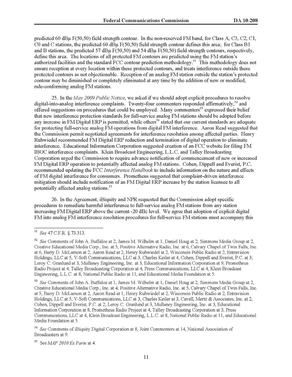
9 NRSC-G202-A 4 DETERMINING AUTHORIZED TOTAL DIGITAL SIDEBAND POWER To determine the authorized total digital sideband Effective Radiated Power (ERP) with respect to the licensed analog ERP for an FM hybrid or extended hybrid IBOC signal, follow these steps: 1) Identify the station s particular digital sideband configuration, specifically; a. service mode (MP1, MP2, MP3, or MP11) b. sideband power levels (utilizing either symmetric or asymmetric configurations) 2) Look up the configuration of interest in the tables below and read the nominal total ERP of the digital signal with respect to the licensed analog ERP in either dbc or percent, using the appropriate table: SIDEBAND CONFIGURATION SERVICE MODE(S) TABLE PAGE Symmetric MP1, MP2, MP3, or MP11 Table 1 9 MP1 Table 2 10 Asymmetric MP2 Table 3 11 MP3 Table 4 12 MP11 Table ) Further calculations must be made from the dbc values obtained from Tables 1-5 to determine the actual power output of the digital transmitter (in watts), or the total power of the IBOC signal (analog and digital power combined). These calculations will be site-specific and will depend upon the particulars of the IBOC transmission facility. Page 8
10 NRSC-G202-A Table 1. Symmetric (Equal) Sidebands Total digital sideband ERP (% of Analog) Service mode Nominal (total) D-A power ratio (dbc), MP1 MP1 MP2 MP3 MP11 Comments % 1.10% 1.20% 1.40% % 1.38% 1.51% 1.76% % 1.74% 1.90% 2.22% % 2.19% 2.39% 2.79% % 2.76% 3.01% 3.51% % 3.48% 3.79% 4.42% % 4.38% 4.77% 5.57% % 5.51% 6.01% 7.01% % 6.94% 7.56% 8.82% % 8.73% 9.52% 11.10% % 10.99% 11.99% 13.98% See Annex 1 FCC notification required (some exceptions apply) FCC informal application required Total digital sideband ERP (dbc ref. to Analog) Service mode Nominal (total) D-A power ratio (dbc), MP1 MP1 MP2 MP3 MP11 Comments See Annex 1 FCC notification required (some exceptions apply) FCC informal application required Page 9
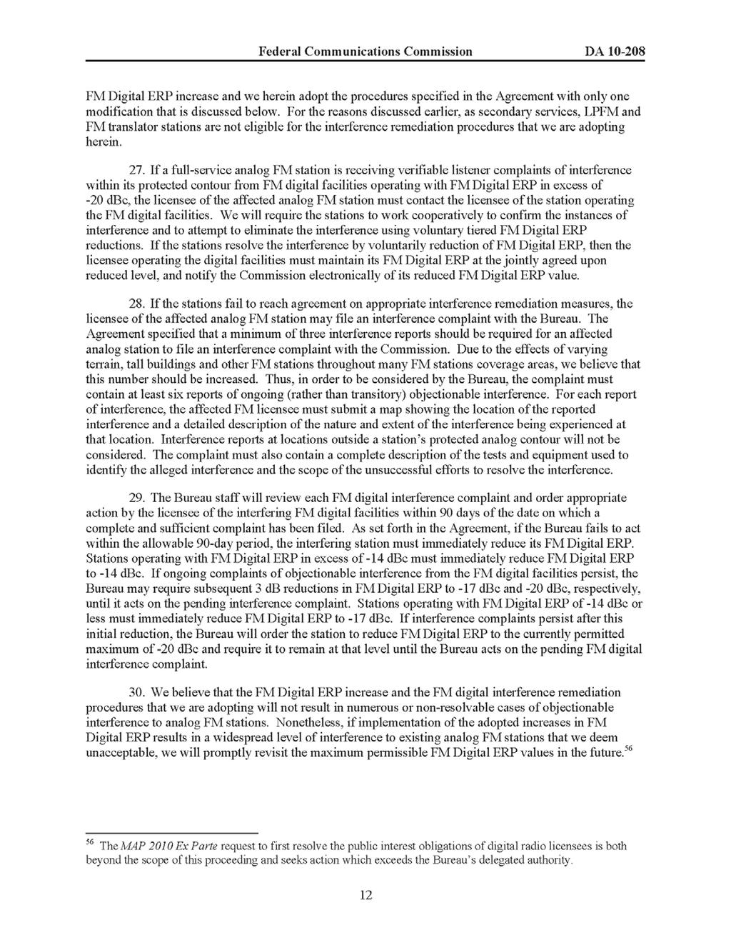
11 NRSC-G202-A 14-Day CPP Draft Table 2. Asymmetric Sidebands, Service Mode MP1 Note: as of the date of adoption of this Guideline, operation with asymmetric sidebands requires an experimental authorization from the FCC. This note will be removed from this Guideline should the FCC approve asymmetrical sideband operation. Lower Power Sideband (dbc) Total Digital Sideband ERP (% of Analog): Service Mode MP1 Note: numbers in parentheses are corresponding total sideband power in symmetric case Higher Power Sideband (dbc) -23 (-20) -22 (-19) -21 (-18) -20 (-17) -19 (-16) -18 (-15) -17 (-14) -16 (-13) -15 (-12) -14 (-11) -13 (-10) -23 (-20) 1.00% 1.13% 1.29% 1.50% 1.76% 2.08% 2.49% 3.01% 3.65% 4.47% 5.50% -22 (-19) 1.26% 1.42% 1.63% 1.89% 2.21% 2.62% 3.14% 3.78% 4.60% 5.63% -21 (-18) 1.58% 1.79% 2.05% 2.37% 2.78% 3.30% 3.95% 4.76% 5.79% -20 (-17) 2.00% 2.25% 2.58% 2.99% 3.50% 4.15% 4.97% 6.00% -19 (-16) 2.51% 2.84% 3.25% 3.76% 4.41% 5.23% 6.26% -18 (-15) 3.16% 3.57% 4.09% 4.74% 5.55% 6.58% -17 (-14) 3.98% 4.50% 5.15% 5.96% 6.99% -16 (-13) 5.01% 5.66% 6.48% 7.51% -15 (-12) 6.31% 7.13% 8.15% -14 (-11) 7.94% 8.97% -13 (-10) 10.00% Lower Power Sideband (dbc) Note: numbers in parentheses are corresponding total sideband power in symmetric case -23 (-20) -22 (-19) -21 (-18) -20 (-17) -19 (-16) -18 (-15) -17 (-14) -16 (-13) -15 (-12) -14 (-11) -13 (-10) -23 (-20) (-19) (-18) (-17) (-16) (-15) (-14) (-13) -15 (-12) -14 (-11) -13 (-10) Total Digital Sideband ERP (dbc ref. to Analog): Service Mode MP1 Higher Power Sideband (dbc) Page 10
12 NRSC-G202-A 14-Day CPP Draft Table 3. Asymmetric Sidebands, Service Mode MP2 Note: as of the date of adoption of this Guideline, operation with asymmetric sidebands requires an experimental authorization from the FCC. This note will be removed from this Guideline should the FCC approve asymmetrical sideband operation. Lower Power Sideband (dbc) Total Digital Sideband ERP (% of Analog): Service Mode MP2 Note: numbers in parentheses are corresponding total sideband power in symmetric case Higher Power Sideband (dbc) -23 (-20) -22 (-19) -21 (-18) -20 (-17) -19 (-16) -18 (-15) -17 (-14) -16 (-13) -15 (-12) -14 (-11) -13 (-10) -23 (-20) 1.10% 1.24% 1.42% 1.65% 1.93% 2.29% 2.74% 3.30% 4.02% 4.92% 6.05% -22 (-19) 1.38% 1.56% 1.79% 2.07% 2.43% 2.88% 3.45% 4.16% 5.06% 6.19% -21 (-18) 1.74% 1.97% 2.25% 2.61% 3.06% 3.63% 4.34% 5.24% 6.37% -20 (-17) 2.19% 2.48% 2.84% 3.29% 3.85% 4.57% 5.46% 6.59% -19 (-16) 2.76% 3.12% 3.57% 4.14% 4.85% 5.75% 6.88% -18 (-15) 3.48% 3.93% 4.49% 5.21% 6.11% 7.24% -17 (-14) 4.38% 4.94% 5.66% 6.56% 7.69% -16 (-13) 5.51% 6.22% 7.12% 8.25% -15 (-12) 6.94% 7.84% 8.97% -14 (-11) 8.73% 9.86% -13 (-10) 10.99% Lower Power Sideband (dbc) Total Digital Sideband ERP (dbc ref. to Analog): Service Mode MP2 Note: numbers in parentheses are corresponding total sideband power in symmetric case Higher Power Sideband (dbc) -23 (-20) -22 (-19) -21 (-18) -20 (-17) -19 (-16) -18 (-15) -17 (-14) -16 (-13) -15 (-12) -14 (-11) -13 (-10) -23 (-20) (-19) (-18) (-17) (-16) (-15) (-14) (-13) (-12) (-11) (-10) -9.6 Page 11
13 NRSC-G202-A 14-Day CPP Draft Table 4. Asymmetric Sidebands, Service Mode MP3 Note: as of the date of adoption of this Guideline, operation with asymmetric sidebands requires an experimental authorization from the FCC. This note will be removed from this Guideline should the FCC approve asymmetrical sideband operation. Lower Power Sideband (dbc) Total Digital Sideband ERP (% of Analog): Service Mode MP3 Note: numbers in parentheses are corresponding total sideband power in symmetric case Higher Power Sideband (dbc) -23 (-20) -22 (-19) -21 (-18) -20 (-17) -19 (-16) -18 (-15) -17 (-14) -16 (-13) -15 (-12) -14 (-11) -13 (-10) -23 (-20) 1.20% 1.35% 1.55% 1.80% 2.11% 2.50% 2.99% 3.60% 4.38% 5.36% 6.59% -22 (-19) 1.51% 1.70% 1.95% 2.26% 2.65% 3.14% 3.76% 4.54% 5.52% 6.75% -21 (-18) 1.90% 2.15% 2.46% 2.85% 3.34% 3.95% 4.73% 5.71% 6.94% -20 (-17) 2.39% 2.70% 3.09% 3.58% 4.20% 4.98% 5.96% 7.19% -19 (-16) 3.01% 3.40% 3.89% 4.51% 5.29% 6.27% 7.50% -18 (-15) 3.79% 4.28% 4.90% 5.68% 6.66% 7.89% -17 (-14) 4.77% 5.39% 6.17% 7.15% 8.38% -16 (-13) 6.01% 6.79% 7.77% 9.00% -15 (-12) 7.56% 8.54% 9.78% -14 (-11) 9.52% 10.76% -13 (-10) 11.99% Lower Power Sideband (dbc) Total Digital Sideband ERP (dbc ref. to Analog): Service Mode MP3 Note: numbers in parentheses are corresponding total sideband power in symmetric case Higher Power Sideband (dbc) -23 (-20) -22 (-19) -21 (-18) -20 (-17) -19 (-16) -18 (-15) -17 (-14) -16 (-13) -15 (-12) -14 (-11) -13 (-10) -23 (-20) (-19) (-18) (-17) (-16) (-15) (-14) (-13) (-12) (-11) (-10) -9.2 Page 12
14 NRSC-G202-A 14-Day CPP Draft Table 5. Asymmetric Sidebands, Service Mode MP11 Note: as of the date of adoption of this Guideline, operation with asymmetric sidebands requires an experimental authorization from the FCC. This note will be removed from this Guideline should the FCC approve asymmetrical sideband operation. Lower Power Sideband (dbc) Total Digital Sideband ERP (% of Analog): Service Mode MP11 Note: numbers in parentheses are corresponding total sideband power in symmetric case Higher Power Sideband (dbc) -23 (-20) -22 (-19) -21 (-18) -20 (-17) -19 (-16) -18 (-15) -17 (-14) -16 (-13) -15 (-12) -14 (-11) -13 (-10) -23 (-20) 1.40% 1.58% 1.81% 2.09% 2.45% 2.91% 3.48% 4.20% 5.11% 6.25% 7.69% -22 (-19) 1.76% 1.99% 2.27% 2.64% 3.09% 3.66% 4.38% 5.29% 6.43% 7.87% -21 (-18) 2.22% 2.50% 2.86% 3.32% 3.89% 4.61% 5.52% 6.66% 8.10% -20 (-17) 2.79% 3.15% 3.60% 4.18% 4.90% 5.80% 6.95% 8.38% -19 (-16) 3.51% 3.97% 4.54% 5.26% 6.17% 7.31% 8.75% -18 (-15) 4.42% 4.99% 5.71% 6.62% 7.76% 9.20% -17 (-14) 5.57% 6.29% 7.19% 8.33% 9.77% -16 (-13) 7.01% 7.91% 9.06% 10.49% -15 (-12) 8.82% 9.96% 11.40% -14 (-11) 11.10% 12.54% -13 (-10) 13.98% Lower Power Sideband (dbc) Note: numbers in parentheses are corresponding total sideband power in symmetric case -23 (-20) -22 (-19) -21 (-18) -20 (-17) -19 (-16) -18 (-15) -17 (-14) -16 (-13) -15 (-12) -14 (-11) -13 (-10) -23 (-20) (-19) (-18) (-17) (-16) (-15) (-14) (-13) -15 (-12) -14 (-11) -13 (-10) Total Digital Sideband ERP (dbc ref. to Analog): Service Mode MP11 Higher Power Sideband (dbc) Page 13
15 5 EXPECTED DIGITAL SIDEBAND POWER SPECTRAL DENSITY (PSD) FOR VARIOUS CONFIGURATIONS Broadcasters typically verify the digital sideband levels of an FM IBOC transmission using a spectrum analyzer. Guideline NRSC-G201-B (NRSC-5 RF Mask Compliance: Measurement Methods and Practice) provides detailed information on how to make these measurements. Table 6 below lists the expected digital sideband power spectral density (PSD) levels as observed on a spectrum analyzer (using the methods of NRSC-G201-B) for digital sideband power ratios from -20 dbc to -10 dbc. Note that while, as shown in Table 1 through Table 5 above, the total digital power in the sidebands varies with service mode, the corresponding PSD values for the digital sidebands do not vary as a function of service mode. Consequently, the values in Table 6 apply to all four service modes. To illustrate this, consider symmetric sideband configurations based upon an MP1 total digital power of -14 dbc. For these configurations, the total digital power varies from dbc (MP1), to dbc (MP2), to dbc (MP3), to dbc (MP11), however, in all of these cases the power spectral density of each digital sideband is constant and equal to (from Table 6) dbc/khz. This is because the additional digital power in the extended hybrid service modes (MP2, MP3, and MP11) results from adding additional digital subcarriers (with a resulting increase in digital sideband bandwidth), with the power in each individual digital subcarrier (and thus the power spectral density) remaining constant and equal to that used in the MP1 service mode. To use Table 6: 1) Determine the desired power ratio (relative to analog, in dbc) of the digital sideband to be measured: a) in symmetric sideband cases, simply use the nominal (total) power ratio (typically from -20 dbc to -10 dbc); b) in asymmetric sideband cases, use the corresponding total sideband power in the symmetric case, not the actual sideband power level. Referring to Tables 2-5, this means that the numbers in italics, in parentheses, are the numbers to use here. 2) Using Table 6, read the nominal digital sideband PSD relative to analog ERP corresponding to the desired digital sideband power ratio. 3) If setting an RF mask value ( limit line ) in the spectrum analyzer for this particular configuration, use the Upper Limit indicated in the table corresponding to the desired digital sideband power ratio. 4) Note that for asymmetric sideband configurations, the expected sideband PSD and RF mask levels will be different for upper and lower digital sidebands. Page 14
16 Table 6. Digital Sideband Power Spectral Density (PSD) and Limit Line Values Based on D-A Ratio (MP1, MP2, MP3, MP11) Digital sideband D-A power ratio relative to analog (dbc) Nominal digital sideband PSD relative to analog ERP (dbc/khz) Upper limit of digital sideband PSD based on original RF mask (dbc/khz) Comments Minimum allowed power Blanket authorization power Maximum allowed power Note that this is the original RF mask level specified in NRSC-5 Page 15
17 ANNEX 1 FCC Order DA Permitting FM stations to voluntarily increase FM hybrid digital ERP (adopted January 27, 2010) This document is reproduced here for reference only. The original document is available on the FCC website under the MM Docket No docket or at the following direct link:
18
19
20
21
22
23
24
25
26
27
28
29
30
31
32
33
34
35
36
37
38
39
40 NRSC Document Improvement Proposal If in the review or use of this document a potential change appears needed for safety, health or technical reasons, please fill in the appropriate information below and , mail or fax to: National Radio Systems Committee c/o Consumer Technology Association Technology & Standards Department 1919 S. Eads St. Arlington, VA FAX: standards@cta.tech DOCUMENT NO. DOCUMENT TITLE: SUBMITTER S NAME: COMPANY: TEL: FAX: ADDRESS: URGENCY OF CHANGE: Immediate At next revision PROBLEM AREA (ATTACH ADDITIONAL SHEETS IF NECESSARY): a. Clause Number and/or Drawing: b. Recommended Changes: c. Reason/Rationale for Recommendation: ADDITIONAL REMARKS: SIGNATURE: DATE: Date forwarded to NAB S&T: Responsible Committee: Co-chairmen: Date forwarded to co-chairmen: FOR NRSC USE ONLY
NATIONAL RADIO SYSTEMS COMMITTEE
 NRSC STANDARD NATIONAL RADIO SYSTEMS COMMITTEE NRSC-2-A Emission Limitation for Analog AM Broadcast Transmission September, 2007 NAB: 1771 N Street, N.W. CEA: 1919 South Eads Street Washington, DC 20036
NRSC-2 Emission Limitation for AM Broadcast Transmission June, 1988
 NRSC-2 Emission Limitation for AM Broadcast Transmission June, 1988 NOTICE NRSC Standards, Bulletins and other technical publications are designed to serve the public interest through eliminating misunderstandings
HD Radio FM Transmission. System Specifications
 HD Radio FM Transmission System Specifications Rev. G December 14, 2016 SY_SSS_1026s TRADEMARKS HD Radio and the HD, HD Radio, and Arc logos are proprietary trademarks of ibiquity Digital Corporation.
HD Radio FM Transmission System Specifications
 HD Radio FM Transmission System Specifications Rev. D February 18, 2005 Doc. No. SY_SSS_1026s TRADEMARKS The ibiquity Digital logo and ibiquity Digital are registered trademarks of ibiquity Digital Corporation.
NOTICE. (Formulated under the cognizance of the CTA R7 Home Networks Committee.)
") ANSI/CTA Standard Control Network Power Line (PL) Channel Specification ANSI/CTA-709.2 S-2017 June 2000 NOTICE Consumer Technology Association (CTA) Standards, Bulletins and other technical publications
ANSI/CTA Standard Control Network Power Line (PL) Channel Specification ANSI/CTA-709.2 S-2017 June 2000 NOTICE Consumer Technology Association (CTA) Standards, Bulletins and other technical publications
NATIONAL RADIO SYSTEMS COMMITTEE
 NRSC STANDARD NATIONAL RADIO SYSTEMS COMMITTEE NRSC-5-D In-band/on-channel Digital Radio Broadcasting Standard April, 2017 NAB: 1771 N Street, N.W. CTA: 1919 South Eads Street Washington, DC 20036 Arlington,
HD Radio AM Transmission System Specifications Rev. F August 24, 2011
 HD Radio AM Transmission System Specifications Rev. F August 24, 2011 SY_SSS_1082s TRADEMARKS HD Radio and the HD, HD Radio, and Arc logos are proprietary trademarks of ibiquity Digital Corporation. ibiquity,
NOTICE. (Formulated under the cognizance of the CTA R6 Portable, Handheld and In-Vehicle Electronics Committee.)
") ANSI/CTA Standard Testing and Measurement Methods for Mobile Loudspeaker Systems ANSI/CTA-2031 R-2014 (Formerly ANSI/CEA-2031 R-2014) September 2008 NOTICE Consumer Technology Association (CTA) Standards,
ANSI/CTA Standard Testing and Measurement Methods for Mobile Loudspeaker Systems ANSI/CTA-2031 R-2014 (Formerly ANSI/CEA-2031 R-2014) September 2008 NOTICE Consumer Technology Association (CTA) Standards,
NOTICE. (Formulated under the cognizance of the CTA R4 Video Systems Committee.)
") ANSI/CTA Standard Antenna Control Interface ANSI/CTA-909-B (Formerly ANSI/) January 2011 NOTICE Consumer Technology Association (CTA) Standards, Bulletins and other technical publications are designed
ANSI/CTA Standard Antenna Control Interface ANSI/CTA-909-B (Formerly ANSI/) January 2011 NOTICE Consumer Technology Association (CTA) Standards, Bulletins and other technical publications are designed
NOTICE. (Formulated under the cognizance of the CTA R4 Video Systems Committee.)
") ANSI/CTA Standard TV Receiving Antenna Performance Presentation Measurement ANSI/CTA-774-C (Formerly ANSI/) November 2014 NOTICE Consumer Technology Association (CTA) Standards, Bulletins and other technical
ANSI/CTA Standard TV Receiving Antenna Performance Presentation Measurement ANSI/CTA-774-C (Formerly ANSI/) November 2014 NOTICE Consumer Technology Association (CTA) Standards, Bulletins and other technical
EIA STANDARD TP-95. Full Mating and Mating Stability Test Procedure for Electrical Connectors EIA/ECA EIA
 EIA STANDARD ANSI/EIA-364-95-1999(R2006) Approved: April 14, 1999 Reaffirmed: March 31, 2006 TP-95 EIA-364-95 Full Mating and Mating Stability Test Procedure for Electrical Connectors EIA/ECA-364-95 APRIL
NOTICE. (Formulated under the cognizance of the CTA R6 Portable, Handheld and In-Vehicle Electronics Committee.)
") ANSI/CTA Standard Performance Specification for Public Alert Receivers ANSI/CTA-2009-B R-2016 (Formerly ANSI/CEA-2009-B) November 2010 NOTICE Consumer Technology Association (CTA) Standards, Bulletins
ANSI/CTA Standard Performance Specification for Public Alert Receivers ANSI/CTA-2009-B R-2016 (Formerly ANSI/CEA-2009-B) November 2010 NOTICE Consumer Technology Association (CTA) Standards, Bulletins
CEA Standard. BTSC System Multichannel Television Sound Recommended Practices CEA-TVSB-5 S-2015
 CEA Standard BTSC System Multichannel Television Sound Recommended Practices CEA-TVSB-5 S-2015 July 1985 NOTICE Consumer Electronics Association (CEA ) Standards, Bulletins and other technical publications
EIA STANDARD TP-27B. Mechanical Shock (Specified Pulse) Test Procedure for Electrical Connectors EIA B ELECTRONIC INDUSTRIES ASSOCIATION
 Test Procedure for Electrical Connectors EIA B ELECTRONIC INDUSTRIES ASSOCIATION") ANSI/-1996 Approved: April 17, 1996 EIA STANDARD TP-27B Mechanical Shock (Specified Pulse) Test Procedure for Electrical Connectors (Revision of EIA-364-27A) MAY 1996 ELECTRONIC INDUSTRIES ASSOCIATION
ANSI/-1996 Approved: April 17, 1996 EIA STANDARD TP-27B Mechanical Shock (Specified Pulse) Test Procedure for Electrical Connectors (Revision of EIA-364-27A) MAY 1996 ELECTRONIC INDUSTRIES ASSOCIATION
NATIONAL RADIO SYSTEMS COMMITTEE
 NRSC REPORT NATIONAL RADIO SYSTEMS COMMITTEE NRSC-R54 Evaluation of LDR's Submission to the NRSC DAB Subcommittee of Selected Laboratory and Field Test Results for its FM and AM Band IBOC System April
EIA STANDARD TP-70B TEMPERATURE RISE VERSUS CURRENT TEST PROCEDURE FOR ELECTRICAL CONNECTORS AND SOCKETS EIA/ECA B. June 2007 EIA/ECA B
 EIA STANDARD ANSI/-2007 Approved: June 8, 2007 TP-70B EIA/ECA-364-70B TEMPERATURE RISE VERSUS CURRENT TEST PROCEDURE FOR ELECTRICAL CONNECTORS AND SOCKETS EIA/ECA-364-70B (Revision of EIA-364-70A) June
FM HD Radio. Field Performance. With. Unequal Digital Sideband Carrier Levels. (Preliminary) ibiquity Digital Corporation
 ibiquity Digital Corporation") FM HD Radio Field Performance With Unequal Sideband Carrier Levels (Preliminary) Revision 01.03 February 22, 2011 ibiquity Corporation 6711 Columbia Gateway Drive Suite 500 Columbia, Maryland 21046 (443)
FM HD Radio Field Performance With Unequal Sideband Carrier Levels (Preliminary) Revision 01.03 February 22, 2011 ibiquity Corporation 6711 Columbia Gateway Drive Suite 500 Columbia, Maryland 21046 (443)
NATIONAL RADIO SYSTEMS COMMITTEE
 NRSC REPORT NATIONAL RADIO SYSTEMS COMMITTEE NRSC-R300 Program Associated Data (PAD) Field Length Study November 2011 NAB: 1771 N Street, N.W. CEA: 1919 South Eads Street Washington, DC 20036 Arlington,
ECC Report 141 Technical supplement. TECHNICAL SUPPLEMENT TO ECC REPORT 141 FUTURE POSSIBILITIES FOR THE DIGITALISATION OF BAND II (87.
 ECC Report 141 Technical supplement TECHNICAL SUPPLEMENT TO ECC REPORT 141 FUTURE POSSIBILITIES FOR THE DIGITALISATION OF BAND II (87.5-108 MHz) April 2012 Technical supplement to ECC REPORT 141 Page 2
NATIONAL RADIO SYSTEMS COMMITTEE
 NRSC REPORT NATIONAL RADIO SYSTEMS COMMITTEE NRSC-R53 Evaluation of USADR's Submission to the NRSC DAB Subcommittee of Selected Laboratory and Field Test Results for its FM and AM Band IBOC System April
Measuring Your IBOC Spectrum. David Maxson
 Measuring Your IBOC Spectrum David Maxson 1 Topics Measuring Power of Digital Waveforms IBOC RF Mask Digital Intermodulation and Interference 2 First Thought IBOC is amazing Truly Hybrid of analog and
NOTICE. (Formulated under the cognizance of the CTA R4 Video Systems Committee.)
") CTA Bulletin Mobile/Handheld DTV Implementation Guidelines CTA-CEB26-B (Formerly CEA-CEB26-B) November 2014 NOTICE Consumer Technology Association (CTA) Standards, Bulletins and other technical publications
CTA Bulletin Mobile/Handheld DTV Implementation Guidelines CTA-CEB26-B (Formerly CEA-CEB26-B) November 2014 NOTICE Consumer Technology Association (CTA) Standards, Bulletins and other technical publications
ENGINEERING COMMITTEE Interface Practices Subcommittee AMERICAN NATIONAL STANDARD ANSI/SCTE
 ENGINEERING COMMITTEE Interface Practices Subcommittee AMERICAN NATIONAL STANDARD ANSI/SCTE 115 2011 Test Method for Reverse Path (Upstream) Intermodulation Using Two Carriers NOTICE The Society of Cable
2010 Radio Show Wrap-up
 October 4, 2010 2010 Radio Show Wrap-up Last week s Radio Show produced by RAB and NAB in Washington, D.C. was an unqualified success. Standing-room only crowds, new technology announcements, fast-paced
AN5009 Application note
 AN5009 Application note Using the S2-LP transceiver under FCC title 47 part 90 in the 450 470 MHz band Introduction The S2-LP is a very low power RF transceiver, intended for RF wireless applications in
AES standard for acoustics Digital interface for microphones. Preview only
 (reaffirmed 2015) AES standard for acoustics Digital interface for microphones Published by Audio Engineering Society, Inc. Copyright 2010 by the Audio Engineering Society Abstract This standard describes
ELECTRICAL TESTING
 ELECTRICAL TESTING 0839.01 Hermon Laboratories Ltd. Harakevet Industrial Zone, Binyamina 30500, Israel Tel. +972-4-6288001 Fax. +972-4-6288277 E-mail: mail@hermonlabs.com TEST REPORT ACCORDING TO: FCC
EXTENDING YOUR HD RADIO FOOTPRINT
 EXTENDING YOUR HD RADIO FOOTPRINT Geoffrey N. Mendenhall, P.E. Vice President Transmission Research and Technology Harris Corporation, Broadcast Communication Division Mason, Ohio PURPOSE: The purpose
From the Transmitter Site
 The Broadcasters Desktop Resource www.thebdr.net edited by Barry Mishkind the Eclectic Engineer From the Transmitter Site Understanding AM NRSC Measurements By James Boyd [January 2013] The FCC requires
WWARA BAND PLANS. Spectrum Use Considerations
 WWARA BAND PLANS Spectrum Use Considerations Definitions: NBFM 16 khz nominal bandwidth VNBD 12.5 khz nominal bandwidth UNBD 6.25 khz nominal bandwidth 10-Meter Band 29.5200-29.5800 Repeater Inputs 20
IEEE Broadband Wireless Access Working Group < Working Group Review of Working Document IEEE 802.
 Project Title Date Submitted IEEE 802.16 Broadband Wireless Access Working Group Specification of operational environments for non-exclusively assigned and licensed bands 2006-09-25
UK Interface Requirement 2022
 UK Interface Requirement 222 Broadcast transmitters operating in frequency bands administered by Ofcom Publication date: April 215 Date Amended: January 218 215/1535/EU Notification number: 214/616/UK
Jampro HD Radio Up Dated & Implementation Costs
 HD Radio (I.B.O.C.) Status and Implementation Jampro HD Radio Up Dated & Implementation Costs Bob Groome Domestic Sales Manager Jampro Antennas / RF Systems, Inc. A Quick Review: What is HD Radio ibiquity
Wireless LAN Consortium
 Wireless LAN Consortium Clause 18 OFDM Physical Layer Test Suite Version 1.8 Technical Document Last Updated: July 11, 2013 2:44 PM Wireless LAN Consortium 121 Technology Drive, Suite 2 Durham, NH 03824
Progressing Cavity Pump Systems for Artificial Lift Surface-drive Systems
 Progressing Cavity Pump Systems for Artificial Lift Surface-drive Systems ANSI/API STANDARD 11D3 FIRST EDITION, JUNE 2008 ISO 15136-2:2006 (Identical), Petroleum and natural gas industries Progressing
DraftETSI EN V1.2.1 ( )
") Draft EN 301 213-2 V1.2.1 (2000-04) European Standard (Telecommunications series) Fixed Radio Systems; Point-to-multipoint equipment; Point-to-multipoint digital radio systems in frequency bands in the
Draft EN 301 213-2 V1.2.1 (2000-04) European Standard (Telecommunications series) Fixed Radio Systems; Point-to-multipoint equipment; Point-to-multipoint digital radio systems in frequency bands in the
BELGIAN INSTITUTE FOR POSTAL AND TELECOMMUNICATIONS
 Page 1 BELGIAN INSTITUTE FOR POSTAL AND TELECOMMUNICATIONS Feature: Decision RAM 24/04/2012 DECISION OF THE COUNCIL OF THE INSTITUTE OF 24 APRIL 2012 ON THE FREQUENCY, AND POWER TRANSMISSION MODES WHICH
ETSI EN V1.4.1 ( )
") EN 300 422-2 V1.4.1 (2015-06) HARMONIZED EUROPEAN STANDARD Electromagnetic compatibility and Radio spectrum Matters (ERM); Wireless microphones in the 25 MHz to 3 GHz frequency range; Part 2: Harmonized
EN 300 422-2 V1.4.1 (2015-06) HARMONIZED EUROPEAN STANDARD Electromagnetic compatibility and Radio spectrum Matters (ERM); Wireless microphones in the 25 MHz to 3 GHz frequency range; Part 2: Harmonized
Base Station (BS) Radio Transmission Minimum Requirements for LTE-U SDL. Presented at the LTE-U Forum workshop on May 28, 2015 in San Diego, CA
 Radio Transmission Minimum Requirements for LTE-U SDL. Presented at the LTE-U Forum workshop on May 28, 2015 in San Diego, CA") Base Station (BS) Radio Transmission Minimum Requirements for LTE-U SDL Presented at the LTE-U Forum workshop on May 28, 2015 in San Diego, CA Disclaimer and Copyright Notification Disclaimer and Copyright
Base Station (BS) Radio Transmission Minimum Requirements for LTE-U SDL Presented at the LTE-U Forum workshop on May 28, 2015 in San Diego, CA Disclaimer and Copyright Notification Disclaimer and Copyright
Spectrum limit masks for digital terrestrial television broadcasting
 Recommendation ITU-R BT.1206-1 (01/2013) Spectrum limit masks for digital terrestrial television broadcasting BT Series Broadcasting service (television) ii Rec. ITU-R BT.1206-1 Foreword The role of the
ENGINEERING COMMITTEE Interface Practices Subcommittee AMERICAN NATIONAL STANDARD ANSI/SCTE
 ENGINEERING COMMITTEE Interface Practices Subcommittee AMERICAN NATIONAL STANDARD ANSI/SCTE 145 2013 Test Method for Second Harmonic Distortion of ives Using a Single Carrier NOTICE The Society of Cable
IBOC AM Transmission Specification
 Appendix A IBOC AM Transmission Specification February 2002 ibiquity Digital Corporation 8865 Stanford Boulevard, Suite 202 Columbia, Maryland 21045 (410) 872-1530 20 Independence Boulevard Warren, New
NATIONAL RADIO SYSTEMS COMMITTEE
 NRSC REPORT NATIONAL RADIO SYSTEMS COMMITTEE NRSC-R55 EIA/NRSC DAR Systems Subjective Tests of Audio Quality and Transmission Impairments Final Report July 21, 1995 NAB: 1771 N Street, N.W. CEA: 1919 South
AN4949 Application note
 Application note Using the S2-LP transceiver under FCC title 47 part 15 in the 902 928 MHz band Introduction The S2-LP is a very low power RF transceiver, intended for RF wireless applications in the sub-1
Shively Labs. Spectral Regrowth
 Shively Labs Spectral Regrowth Abstract Intermodulation products, or spurs, can develop within the analog and digital transmitters in combined systems using high-level injection. In some cases, spurs can
ETSI EN V1.3.1 ( )
") EN 300 422-2 V1.3.1 (2011-08) Harmonized European Standard Electromagnetic compatibility and Radio spectrum Matters (ERM); Wireless microphones in the 25 MHz to 3 GHz frequency range; Part 2: Harmonized
EN 300 422-2 V1.3.1 (2011-08) Harmonized European Standard Electromagnetic compatibility and Radio spectrum Matters (ERM); Wireless microphones in the 25 MHz to 3 GHz frequency range; Part 2: Harmonized
ENGINEERING COMMITTEE Interface Practices Subcommittee AMERICAN NATIONAL STANDARD ANSI/SCTE Measurement Procedure for Noise Power Ratio
 ENGINEERING COMMITTEE Interface Practices Subcommittee AMERICAN NATIONAL STANDARD ANSI/SCTE 119 2006 Measurement Procedure for Noise Power Ratio NOTICE The Society of Cable Telecommunications Engineers
EUROPEAN pr ETS TELECOMMUNICATION February 1996 STANDARD
 FINAL DRAFT EUROPEAN pr ETS 300 118 TELECOMMUNICATION February 1996 STANDARD Second Edition Source: ETSI TC-TE Reference: RE/TE-05049 ICS: 33.020 Key words: PSTN, modems Public Switched Telephone Network
Provided by: Radio Systems, Inc. 601 Heron Drive Bridgeport, NJ
 Provided by: Radio Systems, Inc. 601 Heron Drive Bridgeport, NJ 08014 856-467-8000 www.radiosystems.com Before the Federal Communications Commission Washington, DC 20554 GEN Docket No. 87-839 In the Matter
WirelessUSB LS Radio Module FCC Testing & Verification - AN4006
 WirelessUSB LS Radio Module FCC Testing & Verification - AN4006 Introduction One of the bottlenecks that many product developers encounter in incorporating any radio communication device is facing the
GVSeries. Digital/Analog FM. 3.5 kw 88 kw FM Transmitters
 GVSeries Digital/Analog FM 3.5 kw 88 kw FM Transmitters PUSHRADIO BACKUP AUDIO AUTOMATION PUSH RADIO AUTOMATIC FAIL-SAFE SWITCHOVER OF AUDIO SOURCES GV Series transmitters accept a broad variety of IP,
STUDIO TO TRANSMITTER LINKING SYSTEM
 RFS37 May 1995 (Issue 1) SPECIFICATION FOR RADIO LINKING SYSTEM: STUDIO TO TRANSMITTER LINKING SYSTEM USING ANGLE MODULATION WITH CARRIER FREQUENCY SEPARATION BETWEEN 75 AND 500 khz Communications Division
Method of measuring the maximum frequency deviation of FM broadcast emissions at monitoring stations
 Recommendation ITU-R SM.1268-2 (02/2011) Method of measuring the maximum frequency deviation of FM broadcast emissions at monitoring stations SM Series Spectrum management ii Rec. ITU-R SM.1268-2 Foreword
ENGINEERING COMMITTEE Interface Practices Subcommittee AMERICAN NATIONAL STANDARD ANSI/SCTE
 ENGINEERING COMMITTEE Interface Practices Subcommittee AMERICAN NATIONAL STANDARD ANSI/SCTE 82 2012 Test Method for Low Frequency and Spurious Disturbances NOTICE The Society of Cable Telecommunications
FCC and ETSI Requirements for Short-Range UHF ASK- Modulated Transmitters
 From December 2005 High Frequency Electronics Copyright 2005 Summit Technical Media FCC and ETSI Requirements for Short-Range UHF ASK- Modulated Transmitters By Larry Burgess Maxim Integrated Products
Methods for measurements on digital broadcasting signals
 Recommendation ITU-R SM.1682-1 (09/2011) Methods for measurements on digital broadcasting signals SM Series management ii ITU-R SM.1682-1 Foreword The role of the Radiocommunication Sector is to ensure
Before the Federal Communications Commission Washington, D.C ) ) ) ) ) REPORT AND ORDER. Adopted: February 22, 2011 Released: March 4, 2011
 ) ) ) ) REPORT AND ORDER. Adopted: February 22, 2011 Released: March 4, 2011") Before the Federal Communications Commission Washington, D.C. 20554 In the Matter of Amendment of the Amateur Service Rules to Facilitate Use of Spread Spectrum Communications Technologies WT Docket No.
Before the Federal Communications Commission Washington, D.C. 20554 In the Matter of Amendment of the Amateur Service Rules to Facilitate Use of Spread Spectrum Communications Technologies WT Docket No.
ETSI ES V1.1.1 ( )
") Standard Electromagnetic compatibility and Radio spectrum Matters (ERM); Wireless digital video links operating above 1,3 GHz; Specification of typical receiver performance parameters for spectrum planning
Standard Electromagnetic compatibility and Radio spectrum Matters (ERM); Wireless digital video links operating above 1,3 GHz; Specification of typical receiver performance parameters for spectrum planning
Pearson Education Limited Edinburgh Gate Harlow Essex CM20 2JE England and Associated Companies throughout the world
 Pearson Education Limited Edinburgh Gate Harlow Essex CM20 2JE England and Associated Companies throughout the world Visit us on the World Wide Web at: www.pearsoned.co.uk Pearson Education Limited 2014
AN5029 Application note
 Application note Using the S2-LP transceiver with FEM at 500 mw under FCC title 47 part 15 in the 902 928 MHz band Introduction The S2-LP very low power RF transceiver is intended for RF wireless applications
EUROPEAN pr ETS TELECOMMUNICATION December 1996 STANDARD
 FINAL DRAFT EUROPEAN pr ETS 300 632 TELECOMMUNICATION December 1996 STANDARD Source: ETSI TC-TM Reference: DE/TM-04025 ICS: 33.020 Key words: Analogue, radio, relay, transmission, video Transmission and
AMERICAN NATIONAL STANDARD
 Interface Practices Subcommittee AMERICAN NATIONAL STANDARD Measurement Procedure for Noise Power Ratio NOTICE The Society of Cable Telecommunications Engineers (SCTE) / International Society of Broadband
ETSI EN V1.1.1 ( )
") EN 300 471-2 V1.1.1 (2001-05) Candidate Harmonized European Standard (Telecommunications series) Electromagnetic compatibility and Radio spectrum Matters (ERM); Land Mobile Service; Rules for Access and
EN 300 471-2 V1.1.1 (2001-05) Candidate Harmonized European Standard (Telecommunications series) Electromagnetic compatibility and Radio spectrum Matters (ERM); Land Mobile Service; Rules for Access and
HD Radio Air Interface Design Description Layer 1 FM Rev. G August 23, 2011
 HD Radio Air Interface Design Description Layer 1 FM Rev. G August 23, 2011 SY_IDD_1011s TRADEMARKS HD Radio and the HD, HD Radio, and Arc logos are proprietary trademarks of ibiquity Digital Corporation.
Federal Communications Commission Office of Engineering and Technology Laboratory Division
 April 9, 2013 Federal Communications Commission Office of Engineering and Technology Laboratory Division Guidance for Performing Compliance Measurements on Digital Transmission Systems (DTS) Operating
ETSI TS V1.1.1 ( )
") TS 100 220-1 V1.1.1 (1999-10) Technical Specification Electromagnetic compatibility and Radio spectrum Matters (ERM); Short Range Devices (SRDs); Measurement Specification for Wideband Transmitter Stability
TS 100 220-1 V1.1.1 (1999-10) Technical Specification Electromagnetic compatibility and Radio spectrum Matters (ERM); Short Range Devices (SRDs); Measurement Specification for Wideband Transmitter Stability
Method of measuring the maximum frequency deviation of FM broadcast emissions at monitoring stations. Recommendation ITU-R SM.
 Recommendation ITU-R SM.1268-4 (11/217) Method of measuring the maximum frequency deviation of FM broadcast emissions at monitoring stations SM Series Spectrum management ii Rec. ITU-R SM.1268-4 Foreword
EIA STANDARD TP-66A. EMI Shielding Effectiveness Test Procedure for Electrical Connectors EIA A EIA A
 EIA STANDARD ANSI/-2000(R2007) Approved: May 5, 2000 Reaffirmed: March 1, 2007 TP-66A EMI Shielding Effectiveness Test Procedure for Electrical Connectors (Revision of EIA-364-66) MAY 2000 ELECTRONIC COMPONENTS,
SOCIETY OF CABLE TELECOMMUNICATIONS ENGINEERS INC
 SOCIETY OF CABLE TELECOMMUNICATIONS ENGINEERS INC ENGINEERING COMMITTEE Interface Practices Subcommittee AMERICAN NATIONAL STANDARD ANSI/SCTE 151 2008 Mechanical, Electrical, and Environmental Requirements
FEDERAL COMMUNICATIONS COMMISSION th STREET, S.W. WASHINGTON, DC 20554
 FEDERAL COMMUNICATIONS COMMISSION 445 12 th STREET, S.W. WASHINGTON, DC 20554 February 19, 2004 Report to the Congress on the Low Power FM Interference Testing Program Pub. L. No. 106-553 In accordance
ISO 3213 INTERNATIONAL STANDARD. Polypropylene (PP) pipes Effect of time and temperature on the expected strength
 pipes Effect of time and temperature on the expected strength") INTERNATIONAL STANDARD ISO 3213 Third edition 2009-09-15 Polypropylene (PP) pipes Effect of time and temperature on the expected strength Tubes en polypropylène (PP) Influence du temps et de la température
INTERNATIONAL STANDARD ISO 3213 Third edition 2009-09-15 Polypropylene (PP) pipes Effect of time and temperature on the expected strength Tubes en polypropylène (PP) Influence du temps et de la température
ETSI TR V1.1.1 ( )
") TR 102 475 V1.1.1 (2006-07) Technical Report Electromagnetic compatibility and Radio spectrum Matters (ERM); Wideband Transmission Systems; Data transmission equipment operating in the 2,4 GHz ISM band
TR 102 475 V1.1.1 (2006-07) Technical Report Electromagnetic compatibility and Radio spectrum Matters (ERM); Wideband Transmission Systems; Data transmission equipment operating in the 2,4 GHz ISM band
IBOC FM Transmission Specification
 Appendix A IBOC FM Transmission Specification August 2001 ibiquity Digital Corporation 8865 Stanford Boulevard, Suite 202 Columbia, Maryland 21045 (410) 872-1530 20 Independence Boulevard Warren, New Jersey
ENGINEERING COMMITTEE
 ENGINEERING COMMITTEE Interface Practices Subcommittee AMERICAN NATIONAL STANDARD ANSI/SCTE 45 2012 Test Method for Group Delay NOTICE The Society of Cable Telecommunications Engineers (SCTE) Standards
ISO/IEC INTERNATIONAL STANDARD
 INTERNATIONAL STANDARD This is a preview - click here to buy the full publication ISO/IEC 24769-5 First edition 2012-12-15 Corrected version 2012-12-15 Information technology Automatic identification and
In late 2011, The International Standards
 CISPR 32: New International Standard on Electromagnetic Emissions from Multimedia Equipment DAN HOOLIHAN Hoolihan EMC Consulting Lindstrom, Minnesota USA In late 2011, The International Standards Commission's
AMERICAN NATIONAL STANDARD
 ENGINEERING COMMITTEE Interface Practices Subcommittee AMERICAN NATIONAL STANDARD ANSI/SCTE 151 2015 Mechanical, Electrical, and Environmental Requirements for RF Traps and Filters NOTICE The Society of
IR UK Interface Requirement 2095 High Duty Cycle Network Relay Points (NRPs)
") IR 2095 - UK Interface Requirement 2095 High Duty Cycle Network Relay Points (NRPs) Publication date: January 2015 Date amended: January 2018 2015/1535/EU Notification number: 2014/0480/UK Contents Section
IR 2095 - UK Interface Requirement 2095 High Duty Cycle Network Relay Points (NRPs) Publication date: January 2015 Date amended: January 2018 2015/1535/EU Notification number: 2014/0480/UK Contents Section
INTERNATIONAL STANDARD
 INTERNATIONAL STANDARD ISO 14223-1 First edition 2003-07-01 Radiofrequency identification of animals Advanced transponders Part 1: Air interface Identification des animaux par radiofréquence Transpondeurs
Broadcast Operations
 The Broadcasters Desktop Resource www.thebdr.net edited by Barry Mishkind the Eclectic Engineer Broadcast Operations Modulation Monitoring and the RF Chain By Mark Grant [January 2016] At one time, modulation
ETSI EN V1.1.1 ( )
") EN 300 718-2 V1.1.1 (2001-05) Candidate Harmonized European Standard (Telecommunications series) Electromagnetic compatibility and Radio spectrum Matters (ERM); Avalanche Beacons; Transmitter-receiver
EN 300 718-2 V1.1.1 (2001-05) Candidate Harmonized European Standard (Telecommunications series) Electromagnetic compatibility and Radio spectrum Matters (ERM); Avalanche Beacons; Transmitter-receiver
New Methods for HD Radio Crest Factor Reduction and Pre-correction
 New Methods for HD Radio Crest Factor Reduction and Pre-correction Featuring GatesAir s April 12, 2015 NAB Show 2015 Tim Anderson Radio Product & Business Development Manager Kevin Berndsen Senior Signal
AMERICAN NATIONAL STANDARD
 ENGINEERING COMMITTEE Interface Practices Subcommittee AMERICAN NATIONAL STANDARD ANSI/SCTE 91 2015 Specification for 5/8-24 RF & AC Equipment Port, Female NOTICE The Society of Cable Telecommunications
EUROPEAN ETS TELECOMMUNICATION April 1994 STANDARD
 EUROPEAN ETS 300 198 TELECOMMUNICATION April 1994 STANDARD Source: ETSI TC-TM Reference: DE/TM-04003 ICS: 33.080 Key words: Transmission, radio, video Transmission and Multiplexing (TM); Parameters for
CBRS Commercial Weather RADAR Comments. Document WINNF-RC-1001 Version V1.0.0
 CBRS Commercial Weather RADAR Comments Document WINNF-RC-1001 Version V1.0.0 24 July 2017 Spectrum Sharing Committee Steering Group CBRS Commercial Weather RADAR Comments WINNF-RC-1001-V1.0.0 TERMS, CONDITIONS
ECMA-356. NFCIP-1 - RF Interface Test Methods. 2 nd Edition / June Reference number ECMA-123:2009
 ECMA-356 2 nd Edition / June 2013 NFCIP-1 - RF Interface Test Methods Reference number ECMA-123:2009 Ecma International 2009 COPYRIGHT PROTECTED DOCUMENT Ecma International 2013 Contents Page 1 Scope...
Federal Communications Commission Office of Engineering and Technology Laboratory Division
 Federal Communications Commission Office of Engineering and Technology Laboratory Division Guidance for IEEE 802.11ac and Pre-ac Device Emissions Testing This document provides guidance for emissions testing
ETSI EN V1.1.1 ( )
") EN 300 220-4 V1.1.1 (2017-02) HARMONISED EUROPEAN STANDARD Short Range Devices (SRD) operating in the frequency range 25 MHz to 1 000 MHz; Part 4: Harmonised Standard covering the essential requirements
EN 300 220-4 V1.1.1 (2017-02) HARMONISED EUROPEAN STANDARD Short Range Devices (SRD) operating in the frequency range 25 MHz to 1 000 MHz; Part 4: Harmonised Standard covering the essential requirements
National Standard of the People s Republic of China
 ICS 01.120 A 00 National Standard of the People s Republic of China GB/T XXXXX.1 201X Association standardization Part 1: Guidelines for good practice Click here to add logos consistent with international
ETSI EN V1.5.1 ( ) Harmonized European Standard (Telecommunications series)
 Harmonized European Standard (Telecommunications series)") EN 300 330-2 V1.5.1 (2010-02) Harmonized European Standard (Telecommunications series) Electromagnetic compatibility and Radio spectrum Matters (ERM); Short Range Devices (SRD); Radio equipment in the
EN 300 330-2 V1.5.1 (2010-02) Harmonized European Standard (Telecommunications series) Electromagnetic compatibility and Radio spectrum Matters (ERM); Short Range Devices (SRD); Radio equipment in the
ISO INTERNATIONAL STANDARD. Space systems Space debris mitigation requirements. Systèmes spatiaux Exigences de mitigation des débris spatiaux
 INTERNATIONAL STANDARD ISO 24113 Second edition 2011-05-15 Space systems Space debris mitigation requirements Systèmes spatiaux Exigences de mitigation des débris spatiaux Reference number ISO 24113:2011(E)
ETSI EN V1.1.1 ( )
") EN 301 357-2 V1.1.1 (2000-08) Candidate Harmonized European Standard (Telecommunications series) Electromagnetic compatibility and Radio spectrum Matters (ERM); Analogue cordless wideband audio devices
EN 301 357-2 V1.1.1 (2000-08) Candidate Harmonized European Standard (Telecommunications series) Electromagnetic compatibility and Radio spectrum Matters (ERM); Analogue cordless wideband audio devices
Before the FEDERAL COMMUNICATIONS COMMISSION Washington, D.C. ) ) ) ) )
 ) ) ) )") Before the FEDERAL COMMUNICATIONS COMMISSION Washington, D.C. In the Matter of Amendment of Part 90 of the Commission s Rules ) ) ) ) ) WP Docket No. 07-100 To: The Commission COMMENTS OF THE AMERICAN
Before the FEDERAL COMMUNICATIONS COMMISSION Washington, D.C. In the Matter of Amendment of Part 90 of the Commission s Rules ) ) ) ) ) WP Docket No. 07-100 To: The Commission COMMENTS OF THE AMERICAN
Announced on the 7 th day of May B.E (2010)
") Unofficial translation B.E. 2553 (2010) The National Telecommunications Commission has a policy to revise the technical standards of telecommunication equipment which are used widely, in order to keep
Unofficial translation B.E. 2553 (2010) The National Telecommunications Commission has a policy to revise the technical standards of telecommunication equipment which are used widely, in order to keep
ISO INTERNATIONAL STANDARD. Non-destructive testing Ultrasonic inspection Evaluating electronic characteristics of ultrasonic test instruments
 INTERNATIONAL STANDARD ISO 12710 First edition 2002-09-15 Non-destructive testing Ultrasonic inspection Evaluating electronic characteristics of ultrasonic test instruments Essais non destructifs Contrôle
All Digital HD HD Multiplex Field Trial at KKLZ, Las Vegas
 All Digital HD HD Multiplex Field Trial at KKLZ, Las Vegas Philipp Schmid Research Engineer at Nautel January/February 2018 Presentation Agenda All Digital Signal Configurations All Digital Service Modes
Radio Transmitters and Receivers Operating in the Land Mobile and Fixed Services in the Frequency Range MHz
 Issue 11 June 2011 Spectrum Management and Telecommunications Radio Standards Specification Radio Transmitters and Receivers Operating in the Land Mobile and Fixed Services in the Frequency Range 27.41-960
ETSI EN V2.1.1 ( )
") EN 302 617-2 V2.1.1 (2015-12) HARMONISED EUROPEAN STANDARD Ground-based UHF radio transmitters, receivers and transceivers for the UHF aeronautical mobile service using amplitude modulation; Part 2: Harmonised
EN 302 617-2 V2.1.1 (2015-12) HARMONISED EUROPEAN STANDARD Ground-based UHF radio transmitters, receivers and transceivers for the UHF aeronautical mobile service using amplitude modulation; Part 2: Harmonised
SECTION 2 BROADBAND RF CHARACTERISTICS. 2.1 Frequency bands
 SECTION 2 BROADBAND RF CHARACTERISTICS 2.1 Frequency bands 2.1.1 Use of AMS(R)S bands Note.- Categories of messages, and their relative priorities within the aeronautical mobile (R) service, are given
ETSI EN V1.1.1 ( )
") EN 300 390-2 V1.1.1 (2000-09) Candidate Harmonized European Standard (Telecommunications series) Electromagnetic compatibility and Radio spectrum Matters (ERM); Land Mobile Service; Radio equipment intended
EN 300 390-2 V1.1.1 (2000-09) Candidate Harmonized European Standard (Telecommunications series) Electromagnetic compatibility and Radio spectrum Matters (ERM); Land Mobile Service; Radio equipment intended