W P C A. Worldwide Pollution Control Association. WPCA-Duke Energy. Aug. 28, 2012 Plainfield Sept. 11, Charlotte
|
|
|
- Branden Grant
- 6 years ago
- Views:
Transcription

.")


1 Worldwide Pollution Control Association WPCA-Duke Energy Is Your Precipitator Ready for MATS? Aug. 28, 2012 Plainfield Sept. 11, Charlotte All presentations posted on this website are copyrighted by the Worldwide Pollution Control Association (WPCA). Any unauthorized downloading, attempts to modify or to incorporate into other presentations, link to other websites, or to obtain copies for any other purposes than the training of attendees to WPCA Conferences is expressly prohibited, unless approved in writing by the WPCA or the original presenter. The WPCA does not assume any liability for the accuracy or contents of any materials contained in this library which were presented and/or created by persons who were not employees of the WPCA. Visit our website at W P C A
2 IMPROVING ESP PERFORMANCE WITH VOLTAGE AND RAPPER CONTROL SETTINGS DIAGNOSING PROBLEMS USING VOLTAGE CONTROL METERS PRESENTED AT WPCA/DUKE ENERGY SEMINAR IS YOUR PRECIPITATOR READY FOR MATS? AUG. 28, 2012 PLAINFIELD, IN SEPT. 11, 2012 CHARLOTTE, NC CHRISTOPHER ROGLIERI CHRISTOPHER ROGLIERI KC COTTRELL INC. LODGE COTTRELL INC.
3 Today s Discussion Introduction Safety Transformer Rectifier Controls Operation Troubleshooting Common Upgrades Rapper Controls Operation Troubleshooting Common Upgrades
4 Introduction Understanding controls operation Determine when a problem exists Improving precipitator performance by optimizing control settings General Troubleshooting practices
5 Safety Safety Key Interlock System Lock Out Tag Out (LOTO) Training Permits JHA s, s,jsa s Wear proper PPE
6 Safety (cont d) Most utilities now require flash protection at voltages >120VAC Troubleshooting should be performed by a qualified electrician or properly trained technician. Follow plant guidelines for troubleshooting energized equipment, LOTO and key interlock system.


7 Precipitator Transformer Rectifiers Mechanical Rectifiers 1883 Lodge first demonstrates the use of electrostatic precipitation for the collection of dust particles Lodge makes first attempt on a commercial scale to precipitate dust and fume from gases at Deeside Lead Works 1907 US patent issued to Frederick Cottrell for precipitation process 1908 Cottrell installs first precipitator in US at smelter in California to collect acid mist fumes Vacuum Tube Rectifiers Solid State Rectifiers and Semi Conductor Diodes Sir Oliver Lodge Mechanical Rectifier Dr. Frederick Cottrell


 to ESP E l S")

8 Precipitator Transformer Rectifiers Vacuum Tubes later replaced by Solid State Diodes and Semi- Conductor Rectifier Stacks Diodes configured as a fullwave bridge Pos(+) to Ground Neg(-) to ESP E l S lid S R ifi R l d External Solid State Rectifiers Replaced Obsolete Vacuum Tube diodes


9 Precipitator Transformer Rectifiers Nearly all ESPs updated with microprocessor based automatic y p p high voltage controls
10 Control Operation Maintain highest power levels in electrostatic precipitator p to maximize charging strength and efficiency Modify/adjust power levels for upset conditions, sparks/arcs Ramps power to operator programmed limits/set points of voltage and current, or Reduces power if an upset condition (spark) occurs Continuously ramps to limits/set points (especially after a spark) to maintain maximum precipitation rate Most problems are identified by an alarm All alarms should be proven and addressed
11 Primary Voltage V p Primary Voltage -RMS volts measured after SCR and CLR used for metering and undervoltage trip alarm SCR and snubber circuit varies conduction angle (voltage regulator) driven by AVC microprocessor Control relies on feedback of V p, I p and I s (typ.) (yp) Voltage drop over CLR and field cable Line Voltage typ. (480VAC) Control Voltage (120VAC) Primary Voltage Vp (actual T-R input voltage) Use TRMS meter to check or calibrate
12 Primary Voltage V p Precipitator Primary Voltage between typically a result of a short circuit condition. ex) 600/20 PT 0-20VAC input represents 0-600VAC
13 Primary Voltage V p 0 Volts? Control will trip on Undervoltage if minimum current limit is not met. Primary voltage signal is typ. reduced prior to AVC board or analog volt-meter using step-down transformer. Locate CLR (typ. inside control cabinet, external, or inside T-R oil tank) Primary volt signal wiring typically located at Transformer Tap (LV junction box) or at CLR
14 Primary Voltage V p 0 Volts? (cont d) Measure actual T-R volts after CLR and check ratio. Check fuses (typ. in series with CT primary, located in Control Cabinet, TR LV J-box or CLR enclosure Check for proper voltages at PT primary and secondary
15 Primary Current I p Primary Current -RMS amps measured on L1 or L2 inline with T-R using Current Transformer (CT). Used to drive analog meters Feedback allows control to limit primary current. Converted to voltage signal by adding a shunt (load) resistor. Shunt resistor value determined by control OEM (set feedback scale to primary current nameplate rating of Transformer) Use TRMS clamp ammeter to check or calibrate
16 Primary Current I p Primary Current Signal Schematic shows CT with load resistor for voltage feedback to AVC CT with load resistor
17 Primary Current I p 0 Amps? Open Circuit? Always verify with External TRMS Clamp meter Check connections If applicable, check CT load resistor (disconnect one end)
18 Primary Current I p Overcurrent Trip alarm SCR1 or SCR2 short or misfiring Remove and tape leads, energize control When disconnected, V p and I p should be 0 Otherwise one or both SCRs are shorted or leaking Confirm SCR gate leads connected properly and not switched Replace control board
19 Primary Current I p Breaker Trip SCR1 or SCR2 short or misfiring Short between SCR and breaker Light bulbs can be connected across outputs to check for short Control board firing circuit Replace Breaker
20 Secondary Voltage (V ) s Precipitator secondary kv typ. not a required input to operate HV controls (reference only) Older installations used divider after ACR to create current source to drive meters for display. (50MΩ creates 0-1mA current source scale representing 0-50kV) Most installations use additional signal resistors to create a voltage divider id circuit it for input to the microprocessor control Mean voltage is measured by a resistance type voltage divider circuit.
21 Secondary Voltage (V ) s kv divider circuit scales down T-R operating voltage for input to microprocessor control Analog meter can be used in parallel with signal to microprocessor. Voltage divider typically y installed inside T-R oil tank (newer installations.) On older installations the divider is typ. retro-fitted inside the ground sw. enclosure or pipe & guard. Surge protector prevents lethal voltage outside of T-R junction box or ground switch enclosure.


![sizes 50, 80, 120, 400MΩ) [R 2 ] Signal](/docs-images/80/81635105/images/22-4.jpg "Resistor typ.")
22 Voltage Dividers kv Divider TR primary HV bushing Surge Protector Voltage Divider retrofit on GE Pitts. T-R. [R 1 ]Voltage Divider (typ. sizes 50, 80, 120, 400MΩ) [R 2 ] Signal Resistor typ. installed in LV J- box or AVC cabinet (sized by control vendor to scale input)
23 Secondary Voltage Vs Secondary Voltage feedback Basic kv divider circuit for microprocessor controls kv dividers designed to dissipate heat
24 Secondary Voltage 0 kv? Determine kv divider and sec. signal resistor values (T-R nameplate, schematic, or inspect voltage divider) Check control vendor manual for input scale Voltage divider can be Meg-Ohm tested to confirm value (follow LOTO O and key interlock procedure) Secondary resistor is sometimes adjustable (slide resistor) this value can be checked when disconnected from the circuit. i Meg-Ohm field cable Check surge protectors (Meg-ohm check)
 400MΩ kv dividers 1MΩ sec.")
25 Secondary Voltage Ex: Nameplate Data Double Half-Wave GE 480 Tap T-R (H1/H2) 400MΩ kv dividers 1MΩ sec. resistors 45kVDC [Nameplate]

26 Secondary Voltage (con t) Modern controls typ. use 0-5V or 0-10V scaling for kv feedback and spark detection Signal conditioning boards may be used combining ma and kv metering circuits.
27 Secondary Current Shunt resistor used to scale secondary ma signal. Precipitator load current passes through resistor (connected between ground and low side of rectifier bridge) Shunt resistor provides feedback volt signal to microprocessor based on T-R secondary current rating. Surge protector prevents lethal voltage outside of T-R junction box or ground switch enclosure.
28 Secondary Current Secondary Current Feedback Warning! High voltage potential exists
29 Secondary Current 0 ma? If primary and secondary amps are 0, try short circuit testing TR Current present => Open Circuit inside ESP 0 Current => Open circuit between control and TR Meg-Ohm field cable Check surge protectors (Meg-ohm check) Meg-Ohm TR primary and secondary Open primary => Repair TR Open secondary => check diode stack
30 Normal Operation Precipitator voltage should be above about 30 kilovolts D.C. and 100 volts A.C. in all fields. Precipitator current (milliamps D.C. and amps A.C.) should increase from inlet tto outlet tfields, usually approaching nameplate ratings in the outlet fields. Precipitator sparking should diminish from inlet to outlet fields, seldom exceeding about 50 sparks per minute on any one control.
31 Low Power High Spark Rate Low power and/or excessive sparking: Ash build up/ high hopper level Tracking or cracked insulator Rappers not working (causing excessive build up)
32 Precipitator kw Reaching kv limit? TR Nos. 1 & 2 Spark limited Focus on TR Nos. 3 & 4 (limited at 55kV avg) Primary Voltage at 65-70% Rating High capacitance, slow discharge
33 Precipitator kw Slight increase to kv limit => Increased Power Density V p increased to 75% of nameplate rating Increased Power TR#3 100% TR#4 30%
34 Power Density
35 Power Density
36 Dust Loading Higher dust load => Increase in Voltage Higher dust load > Increase in Voltage Current path restricted
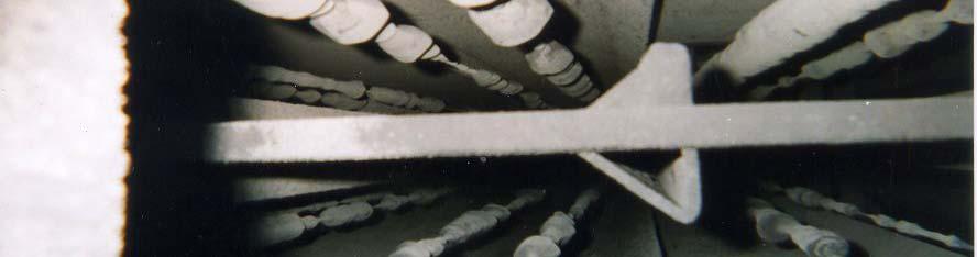
37 Dust Loading High dust loading combined with non-aggressive High dust loading combined with non aggressive electrodes on inlet field


38 Dust Resistivity Fly ash resistivity curve
39 V/I Curve Low-Med Resistivity Precipitators used for range of 10 4 to ohm-cm Preferable resistivity in the range of 10 8 to ohm-cm Basic VI curve for 9-in spacing Low to Medium Resistivity Particulate
40 High Resistivity Dust High resistivity dust layer on collecting plates can neutralize current and reduce voltage Particles do not conduct charge to ground Also known as Back Corona Plot a V/I curve
41 V/I Curve High Resistivity High resistivity effects on Voltage and Current Typ. VI curve for 9-in spacing High Resistivity Particulate
42 Back Corona Back corona and Intermittent Energization modes have been used to find and operate at the knee in the V/I curve during back corona conditions and maintains the power at that point. Power is increased when the back corona condition is no longer present

![12 spacing] Existing T-Rs can be](/docs-images/80/81635105/images/43-3.jpg "re-used with more aggressive")

43 Common Upgrades Rebuild Options Rebuild Weighted Wire ESPs [9 to 12 spacing] Existing T-Rs can be re-used with more aggressive electrodes Lower corona onset or starting voltage Increase power density
44 Common Upgrades Rebuild Options Upgrade to more aggressive electrodes on inlet field Common upgrade for high inlet dust loading Increase electrical sectionalization by adding TRs or Switch Mode Power Supplies Reduces amount of collecting area affected by spark or upset condition. i
45 Common Upgrades HF SMPS (High-Freq.) q) Replace existing conventional 60Hz Transformer Rectifiers (T-Rs) with High Frequency Switch Mode Power Supplies (HF SMPS), ranging up to 25kHz Typically requires 3-phase to precipitator roof MF SMPS (Mid-Freq.) T-Rs can be replaced with MF SMPS or Controls can be upgraded while re-using the existing T-Rs.
46 SMPS (cont d) Reduces ripple, average kv approaches peak kv Increases kv can be attained on inlet and middle fields that are often spark constrained. Small llkv increase often results in significant ifi tincrease in current 5-10% kv increase can result in total power level increase >20% Courtesy of Redkoh Industries
47 Impact on Performance Precipitator OEM s are claiming sizing credits between 10-20% Average kv approaches Peak kv. Significant increase in precipitator current with small increase in operating kv. Fast recovery following spark/arc condition Recent interest es in precipitator p studies and upgrades due to MACT PM limit and DSI opportunities.


48 Rapping Systems Top rapping systems typically grouped by row or field Most common mode of operation is Round Trip using cycle clocks RT time is assigned to each group of rappers Rappers fire in sequence at frequency of RT Time/# Rappers
49 Rapper Controls Top rapped ESPs have been updated with microprocessor based controls. European style rapping systems use tumbling hammer type systems Objective to maintain i collecting efficiency i by forming nominal dust layer and removing with impact force to collecting surface Excessive ash buildup on plates reduces the inter-electrode clearances and causes high spark rates and electrical degradation of the precipitator field


50 Rapping DE CE Action Typical Dust Thickness 1/8 1/4 OK High Dust Build-up 1/4 1/2 Increase cycles and/or intensity Severe Dust Build-up 1/2 1 Change or upgrade rapping design

51 Rapping Opacity Average?
52 Rapping Double spike detected every 5 min Correlates to outlet field rapping program (Round Trip Time/ No. Rappers) SPIKES DETECTED 5MIN INTERVAL RAPPERS OFF
 Startup Rappers on, program change Rappers")
53 Rapping Startup Spikes Increasing Rappers Off Reduced intensity on Outlet field rappers Reduced round trip time (less time between raps) Startup Rappers on, program change Rappers off

54 Rapping Changes do not result in immediate results! Rapping programs and power levels should be monitored throughout shift at steady load Target Lower Baseline Decrease Spiking Peaks and frequency Rappers off Program modified
55 Rapping If modifications are made to the rapping program, the following should be kept in mind: Excessive rapping of collecting electrodes causes re- entrainment of collected ash, and loss of collection efficiency. Excessive rapping may cause fatigue failure of internal components. Inadequate rapping causes high spark rates, low power, and loss of collection efficiency. Because particulate collection is concentrated at the inlet of the precipitator, rapping should be hardest and most frequent on the inlet field, and progressively less on downstream fields.
56 Rapping Fine tuned rapping program in operation at full load Fine tuned rapping program in operation at full load (P-C med. sulfur coal)
57 High Gas Velocities and Re-entrainment PROBLEM: Excessive emissions while precipitator it t is operating at thigh h power. SYMPTOMS: Normal primary and secondary voltage. Normal primary and secondary current. Abnormally high stack opacity. CAUSES: Rappers misadjusted to excessively high hintensity it or short cycles. Volume of flue gas above design. Poor gas distribution within precipitator due to pluggage of perforated distribution plate, or dust buildup in plenum.
58 Troubleshooting Impulse Rappers SHORT CIRCUIT (SINGLE RAPPER) Coil Cover Phenolic Tube Heavy Duty Solenoid Coil High level current alarm Shorted coil Coil tube wear Shorted field cable OPEN CIRCUIT Low level current alarm Disconnected field cable or coil Solid Rod Hammer Sealing Boot Stationary ti Rapper Hammer Anvil Lower Casing COIL RESISTANCE Resistance can be measured at rapper or control cabinet Check with rapper vendor for acceptable values and compare all values
59 Troubleshooting using Waveforms Oscilloscope waveforms are obtained by connecting across the current sensing resistor (providing feedback to the controller) Measures voltage across resistor and compares to normal value Short circuit condition Control detects high level voltage Fires for 1 half cycle to protect the components from high current
60 Common Upgrades Tumbling Hammer to Top Rapping Conversion. Top rapping systems using magnetic impulse type rappers offer more flexibility for changing intensity and rapping frequencies Splitting anvil beams Older P-C ESPs had as many as 9 or 10 CE s per anvil beam Splitting anvil beams increases rapping density and sectionalization, reduces fly ash re-entrainment
61 Common Upgrades Splitting anvil beams
62 Common Upgrades Flue Gas Conditioning SO 3 conditioning used to improve electrical characteristics of fly ash (improve resistivity) NH 3 conditioning used to agglomerate fly ash particles Flue gas conditioning used in an effort to offset the adverse affect of low sulfur coal, particulate fines, and dhigh hresistivity. it
63 QUESTIONS? THANK YOU
Duke Energy Seminar September 3 5, 2008 Concord, NC
 Duke Energy Seminar September 3 5, 2008 Concord, NC An Introduction to Precipitator Controls Systems The aim of this presentation is to: Identify the global requirement of an ESP Control System Identify
Power Supply and automatic Voltage
 Power Supply and automatic Voltage Control 12-09-13 ESP Controls Understanding ESP Controls Power Supply System The power supply system is designed to provide voltage to the electrical field (or bus section)
REDKOH INDUSTRIES SWITCH MODE POWER SUPPLY DEMO UNIT
 Installation Guide REDKOH INDUSTRIES SWITCH MODE POWER SUPPLY DEMO UNIT These Demo Units are typically available for 30 day loans. Redkoh Requests that the customer pays the freight of the unit to and
Particulate Control O&M Training. APC/PCUG Conference July 12-16, 2009 The Woodlands, TX
 Particulate Control O&M Training APC/PCUG Conference July 12-16, 2009 The Woodlands, TX WPCA Particulate Training Seminar July 11, 2009 ESP Power Supply Choices Slide No 1 Precipitator Power Supplies Conventional
Redkoh Industries RK2000. Microprocessor Transformer Rectifier Control for Electrostatic Precipitators V1.40
 Redkoh Industries RK2000 Microprocessor Transformer Rectifier Control for Electrostatic Precipitators V1.40 Redkoh Industries 2009 TABLE OF CONTENTS INTRODUCTION: Maximum Flexibility with Minimum Emissions
4 th generation of Coromax pulse generators for ESP s
 4 th generation of Coromax pulse generators for ESP s Victor Reyes FLSmidth Airtech Denmark vicr@flsairtech.com Peter Elholm FLSmidth Airtech Denmark PE@flsairtech.com 1 Abstract: The first plants using
AI & CHYUN EWSLETTER Product Feature ESP Upgrade Enhance Performance: Rigid Discharge Electrode & High Frequency T/R* Contents Product Feature
 1 1 TAI & CHYUN NEWSLETTER Product Feature ESP Upgrade to Enhance Performance: Rigid Discharge Electrode & High Frequency T/R* Few years ago, China passed the stringent emission regulations of below 20
CUSTOMIZED RIGID DISCHARGE ELECTRODES SHOW SUPERIOR PERFORMANCE IN PULP & PAPER APPLICATIONS
 CUSTOMIZED RIGID DISCHARGE ELECTRODES SHOW SUPERIOR PERFORMANCE IN PULP & PAPER APPLICATIONS Mick Chambers Proposal Manager Southern Environmental, Inc. Pensacola, Florida Gary J. Grieco Consultant Air
NEO TELE-TRONIX PVT. LTD. 6/7 Bijoygarh, Kolkata , Tel : ; Fax :
 NEO TELE-TRONIX PVT. LTD. 6/7 Bijoygarh, Kolkata - 700 032, Tel : 033 2477 3126; Fax : 033 2477 2403 www.ntplindia.com SPECIFICATION NTPL MAKE MICRO-CONTROLLER BASED AUTOMATIC 50KV/10A AC HIGH VOLTAGE
Effect of High Frequency Power Supplies on the Electrostatic Precipitator Collection Efficiency as Compared to Conventional Transformer Rectifiers
 Effect of High Frequency Power Supplies on the Electrostatic Precipitator Collection Efficiency as Compared to Conventional Transformer Rectifiers Gerald Chauke and Rupert Gouws School of Electrical, Electronic
Development of Measuring and Computer Interface System for an Industrial Electrostatic Precipitator
 Helwan University From the SelectedWorks of Omar H. Abdalla April, 2007 Development of Measuring and Computer Interface System for an Industrial Electrostatic Precipitator Omar H. Abdalla Soliman M. Sharaf
PRE COMMISSIONING TESTS ON EQUIPMENT AT 33/11 KV SUB STATIONS. IR Values are to be read on the megger by meggering the Power transformer
 PRE COMMISSIONING TESTS ON EQUIPMENT AT 33/11 KV SUB STATIONS TESTS ON TRANSFORMERS 1. IR Values This is measured to measure the Insulation Resistance of the whole transformer. a) For 33/11 KV Power Transformer
Substation Preventive Maintenance
 Substation Preventive Maintenance PROVINCIAL ELECTRICITY AUTHORITY 1 Presentation Contents 1) A kind of substation 2) Electrical equipment details of AIS substation 3) Electrical equipment details of GIS
INSTALLATION AND MAINTENANCE MANUAL FOR GROUND MONITOR GM-250 COPYRIGHT 1983 AMERICAN MINE RESEARCH, INC.
 INSTALLATION AND MAINTENANCE MANUAL FOR GROUND MONITOR GM-250 COPYRIGHT 1983 AMERICAN MINE RESEARCH, INC. MANUAL PART NUMBER 180-0036 ORIGINAL: 1-17-83 REVISION: B (8-26-86) NOT TO BE CHANGED WITHOUT MSHA
Electronically Commutated (EC) Motor Control with Solo, Select and Sync PWM Boards
 Motor Control with Solo, Select and Sync PWM Boards") Electronically Commutated (EC) Motor Control with Solo, Select and Sync PWM Boards The Solo, Select and Sync PWM boards provide a pulse-width modulated (PWM) signal to the EC motor to control fan speed.
Electronically Commutated (EC) Motor Control with Solo, Select and Sync PWM Boards The Solo, Select and Sync PWM boards provide a pulse-width modulated (PWM) signal to the EC motor to control fan speed.
Application of multi-phase HV rectifiers in electrostatic precipitators
 Application of multi-phase HV rectifiers in electrostatic precipitators V. Reyes, B. Bidoggia FLSmidth A/S, Airtech, Denmark Corresponding author: VICR@flsmidth.com, BEBI@flsmidth.com Abstract This paper
Back to the Basics Current Transformer (CT) Testing
 Testing") Back to the Basics Current Transformer (CT) Testing As test equipment becomes more sophisticated with better features and accuracy, we risk turning our field personnel into test set operators instead of
Back to the Basics Current Transformer (CT) Testing As test equipment becomes more sophisticated with better features and accuracy, we risk turning our field personnel into test set operators instead of
Industrial Electrician Level 3
 Industrial Electrician Level 3 Industrial Electrician Unit: C1 Industrial Electrical Code I Level: Three Duration: 77 hours Theory: Practical: 77 hours 0 hours Overview: This unit is designed to provide
UNISONIC TECHNOLOGIES CO., LTD
 UNISONIC TECHNOLOGIES CO., LTD GROUND FAULT INTERRUPTER DESCRIPTION The UTC GM1851 can specially provide ground fault protection for AC power outlets in consumer and industrial environments. As ground
High frequency operated DC power source for electrostatic precipitators
 AR-70/1000 V.01 ESP power controller High frequency operated DC power source for electrostatic precipitators Why using high frequency instead of 50Hz SCR power AR-70/1000 product: Basic functionality and
Section 3. Test Procedures
 Section 3. Information contained within this section shall be read in conjunction with all sections of this manual Non - Compliant Test Results Where acceptable results are not attained in accordance with
DUAL OUTPUT AC CURRENT/VOLTAGE TRANSDUCER
 OPERATOR S MANUAL DUAL OUTPUT AC CURRENT/VOLTAGE TRANSDUCER Masibus Automation & Instrumentation Pvt. Ltd. B/30, GIDC Electronics Estate, Sector-25, Gandhinagar-382044, Gujarat, India Web Site: www..com
High Frequency Sinewave Guardian TM Filter
 High Frequency Sinewave Guardian TM Filter 380V 480V TECHNICAL REFERENCE MANUAL FORM: SHF-TRM-E REL. April 2015 REV. 001 2015 MTE Corporation Caution Prior to start up; confirm the drive operation mode
DLVP A OPERATOR S MANUAL
 DLVP-50-300-3000A OPERATOR S MANUAL DYNALOAD DIVISION 36 NEWBURGH RD. HACKETTSTOWN, NJ 07840 PHONE (908) 850-5088 FAX (908) 908-0679 TABLE OF CONTENTS INTRODUCTION...3 SPECIFICATIONS...5 MODE SELECTOR
Microprocessor Control Board Set Up Procedures (OR PLC)
") Microprocessor Control Board Set Up Procedures (OR-00 PLC) SWITCHES/PUSHBUTTONS Push Buttons at display SW Enter button SW Back button SW Down SW UP Back light on/off switch Rotary switches on main board
Microprocessor Control Board Set Up Procedures (OR-00 PLC) SWITCHES/PUSHBUTTONS Push Buttons at display SW Enter button SW Back button SW Down SW UP Back light on/off switch Rotary switches on main board
Group F : Sl. No. - 1) 33/0.403 KV, 100 KVA Station Transformer GUARANTEED & OTHER TECHNICAL PARTICULARS. Table : A
 33/0.403 KV, 100 KVA Station Transformer GUARANTEED & OTHER TECHNICAL PARTICULARS. Table : A") Group F : No. - 1) 33/0.403 KV, 100 KVA Station Transformer GUARANTEED & OTHER TECHNICAL PARTICULARS Table : A No. Description 1. Make & Manufacturer 2. Place of Manufacturer 3. Voltage Ratio 4. Rating
Group F : No. - 1) 33/0.403 KV, 100 KVA Station Transformer GUARANTEED & OTHER TECHNICAL PARTICULARS Table : A No. Description 1. Make & Manufacturer 2. Place of Manufacturer 3. Voltage Ratio 4. Rating
FAN1851A Ground Fault Interrupter
 Ground Fault Interrupter www.fairchildsemi.com Features Improved performance over industry equivalents Tight fault current range (Typ ±00µA) Temperature compensated fault current characteristics No external
Electrical Measurement Safety. Sponsored By:
 Electrical Measurement Safety Sponsored By: About the Viewer Panel Slides: Go to the Links tab at the top and click on the link to download the PDF of the slides If you re watching the archive version,
UBC Technical Guidelines Section Edition Medium-Voltage Transformers Page 1 of 5
 Page 1 of 5 1.0 GENERAL 1.1 Coordination Requirements.1 UBC Energy & Water Services.2 UBC Building Operations 1.2 Description.1 UBC requirements for Substation Transformers. 2.0 MATERIAL AND DESIGN REQUIREMENTS
Drives 101 Lesson 3. Parts of a Variable Frequency Drive (VFD)
") Drives 101 Lesson 3 Parts of a Variable Frequency Drive (VFD) This lesson covers the parts that make up the Variable Frequency Drive (VFD) and describes the basic operation of each part. Here is the basics
Drives 101 Lesson 3 Parts of a Variable Frequency Drive (VFD) This lesson covers the parts that make up the Variable Frequency Drive (VFD) and describes the basic operation of each part. Here is the basics
Troubleshooting and Maintenance
 6 In This Chapter... page... 2 Monitoring Trip Events, History, & Conditions.. 5 Restoring Factory Default Settings... 8 Maintenance and Inspection... 9 Warranty... 16 6 2 Safety Messages Please read the
WATT TRANSDUCER. Instruction Manual
 WT 9200 WATT TRANSDUCER Instruction Manual IM-2 September 2003 USA: 6428 Ridglea Drive, Watauga, Texas 76148 Tel/Fax 1-817-427-2060/2067 E-mail: wes@westecinstruments.com SPECIFICATIONS Power Supply Input
Addendum to Instructions for Installation, Operation and Maintenance of Digitrip 3000 Protective Relays
 Dual-Source Power Supply Addendum to I.B. 17555 Addendum to Instructions for Installation, Operation and Maintenance of Digitrip 3000 Protective Relays Table of Contents Page 1.0 Introduction...1 2.0 General
+ 24V 3.3K - 1.5M. figure 01
 ELECTRICITY ASSESSMENT 35 questions Revised: 08 Jul 2013 1. Which of the wire sizes listed below results in the least voltage drop in a circuit carrying 10 amps: a. 16 AWG b. 14 AWG c. 18 AWG d. 250 kcmil
Lecture 36 Measurements of High Voltages (cont) (Refer Slide Time: 00:14)
 (Refer Slide Time: 00:14)") Advances in UHV Transmission and Distribution Prof. B Subba Reddy Department of High Voltage Engg (Electrical Engineering) Indian Institute of Science, Bangalore Lecture 36 Measurements of High Voltages
Advances in UHV Transmission and Distribution Prof. B Subba Reddy Department of High Voltage Engg (Electrical Engineering) Indian Institute of Science, Bangalore Lecture 36 Measurements of High Voltages
Calhoon MEBA Engineering School. Study Guide for Proficiency Testing Industrial Electronics
 Calhoon MEBA Engineering School Study Guide for Proficiency Testing Industrial Electronics January 0. Which factors affect the end-to-end resistance of a metallic conductor?. A waveform shows three complete
High Frequency SineWave Guardian TM Filter
 High Frequency SineWave Guardian TM Filter 380V 480V TECHNICAL REFERENCE MANUAL WARNING High Voltage! Only a qualified electrician can carry out the electrical installation of this filter. Quick Reference
Application of High-Voltage Power Supply on Electrostatic Precipitator
 World Journal of Engineering and Technology, 2017, 5, 269-274 http://www.scirp.org/journal/wjet ISSN Online: 2331-4249 ISSN Print: 2331-4222 Application of High-Voltage Power Supply on Electrostatic Precipitator
TOSHIBA International Corp
 TOSHIBA International Corp GUIDE SPECIFICATIONS THREE PHASE UNINTERRUPTIBLE POWER SYSTEM TOSHIBA 4200FA 30 kva CT Internal Battery UPS GUIDE SPECIFICATIONS 1 (30 kva CT) 1.0 SCOPE 1.1 System This specification
Section L5: PRE-ENERGIZATION TEST PROCEDURES FOR LOAD-ONLY ENTITIES AND TRANSMISSION-ONLY ENTITIES
 Section L5: PRE-ENERGIZATION TEST PROCEDURES FOR LOAD-ONLY ENTITIES AND TRANSMISSION-ONLY ENTITIES PURPOSE The following is PG&E's procedure for pre-energization inspections. For PG&E to provide the Load
TIG 250 AC-DC. POWER SOURCE art
 CEBORA S.p.A. 1 TIG 250 AC-DC POWER SOURCE art. 236.76 SERVICE MANUAL CEBORA S.p.A. 2 CONTENTS 1 - GENERAL INFORMATION... 3 1.1 - Introduction.... 3 1.2 - General service policy.... 3 1.3 - Safety information....
Basic Electrical Training
 Basic Electrical Training Electricians Tools Explain how various hand tools are used by an electrician Discuss the safe use of hand tools and power tools Perform basic calculations and measurement conversions
SureTest Model ST-1THD & ST-1THDC Instructions
 #61-156 #61-157 #61-158 SureTest Model ST-1THD & ST-1THDC Instructions Introduction The SureTest family of Circuit/distortion analyzers identify problems common to electrical circuits and harmonic distortion
Numbering System for Protective Devices, Control and Indication Devices for Power Systems
 Appendix C Numbering System for Protective Devices, Control and Indication Devices for Power Systems C.1 APPLICATION OF PROTECTIVE RELAYS, CONTROL AND ALARM DEVICES FOR POWER SYSTEM CIRCUITS The requirements
DATA SHEET FOR LIGHTING TRANSFORMER APPD. BY VDV PROJECT NO
 PART - A : SPECIFIC REQUIREMENTS THIS DATA SHEET IS APPLICABLE FOR IN BOILER A CLIMATIC CONDITIONS PACKAGE 1 DESIGN AMBIENT TEMPERATURE 45 C 2 ALTITUDE ( ABOVE MSL ) 6.71 MTRS. 3 RELATIVE HUMIDITY 74 %
7. INSPECTION AND TEST PROCEDURES
 7.1 Switchgear and Switchboard Assemblies A. Visual and Mechanical Inspection 1. Compare equipment nameplate data with drawings and specifications. 2. Inspect physical and mechanical condition. 3. Inspect
Installation Manual DOC R1 Date: 05/27/99. Plug-in Meter Installation Manual
 Installation Manual DOC-4004-5015-R1 Date: 05/27/99 Plug-in Meter Installation Manual Document Number: Doc-4004-5015-R1 Document Release Date: 5/99 Copyright 1999 TeCom Inc. All rights reserved. No part
OPERATION & SERVICE MANUAL FOR FC 110 AC POWER SOURCE
 OPERATION & SERVICE MANUAL FOR FC 100 SERIES AC POWER SOURCE FC 110 AC POWER SOURCE VERSION 1.3, April 2001. copyright reserved. DWG No. FC00001 TABLE OF CONTENTS CHAPTER 1 INTRODUCTION... 1 1.1 GENERAL...
Aspects on High Frequency Power Supplies for ESPs
 Ranstad et al. 117 Aspects on High Frequency Power Supplies for ESPs P. Ranstad and J. Linner Alstom Power Sweden Abstract High-frequency power supplies were originally introduced on the ESP market by
REQUIRED SKILLS AND KNOWLEDGE UEENEEE104A. Topic and Description NIDA Lesson CARD #
 REQUIRED SKILLS AND KNOWLEDGE UEENEEE104A KS01-EE104A Direct current circuits T1 Topic and Description NIDA Lesson CARD # Basic electrical concepts encompassing: electrotechnology industry static and current
MS8268 HANDHELD DIGITAL MULTIMETER OPERATOR S INSTRUCTION MANUAL
 MS8268 HANDHELD DIGITAL MULTIMETER OPERATOR S INSTRUCTION MANUAL Table of Contents TITLE PAGE 1. GENERAL INSTRUCTIONS 1 1.1 Precaution safety measures 1 1.1.1 Preliminary 1 1.1.2 During use 2 1.1.3 Symbols
AC Current Monitor model ACM-2
 1.0 Safety Warnings The ACM-2 AC Current Monitor should be installed only by qualified technical personnel with knowledge of industrial electrical wiring and the requirements of the national and local
Network Analyzer for Low-, Medium- and High-Voltage Networks
 Technical data Network nalyzer for Low-, Medium- and High-Voltage Networks Model PQ-Box 150 1 Fault detection 1 Evaluation of voltage quality according to EN50160 and IEC61000-2-2 (2-4) 1 FFT nalysis up
Apprentice Electrical Technician Test (ETT) Preparation Guide
 Preparation Guide") Apprentice Electrical Technician Test (ETT) Preparation Guide APPRENTICE ELECTRICAL TECHNICIAN TEST (ETT) About the Test There are 40 questions with a maximum time limit of three hours. This is a closed
Apprentice Electrical Technician Test (ETT) Preparation Guide APPRENTICE ELECTRICAL TECHNICIAN TEST (ETT) About the Test There are 40 questions with a maximum time limit of three hours. This is a closed
Technical. Application. Assembly. Availability. Pricing. Phone
 6121 Baker Road, Suite 108 Minnetonka, MN 55345 www.chtechnology.com Phone (952) 933-6190 Fax (952) 933-6223 1-800-274-4284 Thank you for downloading this document from C&H Technology, Inc. Please contact
The Importance of the Neutral-Grounding Resistor. Presented by: Jeff Glenney, P.Eng. and Don Selkirk, E.I.T.
 The Importance of the Neutral-Grounding Resistor Presented by: Jeff Glenney, P.Eng. and Don Selkirk, E.I.T. Presentation Preview What is high-resistance grounding (HRG)? What is the purpose of HRG? Why
PRODUCT/TEST MANUAL 2V162K12 VOLTAGE REGULATOR RELAY
 Sheet 1 of 15 TEST DATE: CUSTOMER: SERIAL NO: OLTC ACKNOWLEDGE SETUP AUTOMATIC or FEEDBACK CONTROL PRODUCT/TEST MANUAL 2V162K12 VOLTAGE REGULATOR RELAY Issue Date Level A 06/01/1997 Initial issue. Summary
Aggravation with voltage?
 Voltage Regulator Aggravation with voltage? At photovoltaic plants, long lines or increasing energy consumption?...then the voltage regulator can help Quick regulation from 300-700 ms Regulation of each
TENTATIVE PP225D120. POW-R-PAK TM 225A / 1200V Half Bridge IGBT Assembly. Description:
 Description: The Powerex is a configurable IGBT based power assembly that may be used as a converter, chopper, half or full bridge, or three phase inverter for motor control, power supply, UPS or other
Rev /13 SSRMAN-1B SERIES USERS MANUAL SSR INTELLIGENT BURST FIRING CONTROL COPYRIGHT 2013 NUWAVE TECHNOLOGIES, INC.
 Rev.2.2 12/13 MAN-1B SERIES USERS MANUAL INTELLIGENT BURST FIRING CONTROL COPYRIGHT 2013 MAN-1B Users Manual Page 2 TABLE OF CONTENTS 1. Ordering Codes... 2 2. Description... 2 2.1 Features... 3 3. Installation
T/3000 T/3000. Substation Maintenance and Commissioning Test Equipment
 T/3000 Substation Maintenance and Commissioning Test Equipment MULTI FUNCTION SYSTEM FOR TESTING SUBSTATION EQUIPMENT SUCH AS: CURRENT, VOLTAGE AND POWER TRANSFORMERS, ALL TYPE OF PROTECTION RELAYS, ENERGY
TOS5300 SERIES Hipot Tester/Hipot Tester with Insulation Resistance Test
 A new standard for Hipot & Insulation resistance testing Applied to World-Wide input voltage TOS5301 TOS5300 TOS5302 TOS5300(ACW) TOS5301(ACW/DCW) TOS5302(ACW/IR) New low-cost standard model that provides
Low profile safety relay with forcibly guided double contacts FEATURES. Relay height, 14.5mm. 4a2b
 Low profile safety relay with forcibly guided double contacts SFN4D RELAY 3.3 33.0 FEATURES Relay complies with EN 020, Type B. Polarized magnet system with snap action function Tolerance ±0.3 mm Weight
2) The larger the ripple voltage, the better the filter. 2) 3) Clamping circuits use capacitors and diodes to add a dc level to a waveform.
 The larger the ripple voltage, the better the filter. 2) 3) Clamping circuits use capacitors and diodes to add a dc level to a waveform.") TRUE/FALSE. Write 'T' if the statement is true and 'F' if the statement is false. 1) A diode conducts current when forward-biased and blocks current when reverse-biased. 1) 2) The larger the ripple voltage,
TRUE/FALSE. Write 'T' if the statement is true and 'F' if the statement is false. 1) A diode conducts current when forward-biased and blocks current when reverse-biased. 1) 2) The larger the ripple voltage,
MODEL INFORMATION. AccuLoss MODELS ALMS 2100, ALMS 4100, ALMS 4200, ALMS 6200 & ALMS 4300
 AccuLoss MODELS ALMS 2100, ALMS 4100, ALMS 4200, ALMS 6200 & ALMS 4300 The measurement of electric power and energy at high voltages and currents at low power factors is becoming increasingly important
Rev.8.8 SSRMAN-1P SERIES USERS MANUAL SSR INTELLIGENT PHASE ANGLE CONTROL MODULE COPYRIGHT 2015 NUWAVE TECHNOLOGIES, INC.
 Rev.8.8 MAN-1P SERIES USERS MANUAL INTELLIGENT PHASE ANGLE CONTROL MODULE COPYRIGHT 2015 MAN-1P Users Manual Page 2 TABLE OF CONTENTS 1. Ordering Codes... 2 2. Description... 3 2.1 Features... 3 3. Installation
N. TEST TEST DESCRIPTION
 Multi function system for testing substation equipment such as: current, voltage and power transformers, over-current protection relays, energy meters and transducers Primary injection testing capabilities
Commissioning and Maintenance of Power Factor Correction Systems
 Dear Customer, We would like to thank you for choosing a power factor correction system from FRAKO Kondensatoren- und Anlagenbau GmbH. It is a pleasure to welcome you into the ever-expanding circle of
VXR S SERIES 1.0 DESCRIPTION 1.1 FEATURES 1.2 COMPLIANCE 1.3 PACKAGING 1.4 SIMILAR PRODUCTS AND ACCESSORIES
 VXR15-2800S SERIES HIGH RELIABILITY COTS DC-DC CONVERTERS Models Available Input: 9 V to 60 V continuous, 6 V to 100 V transient 15 W, single output of 3.3 V, 5 V, 12 V, 15 V -55 C to 105 C Operation 1.0
AMIK 200 / 201 Technical Data Sheet
 AMIK 200 / 201 Technical Data Sheet AMIK Special Features MODBUS (RS-485) Communication available only on Amik 201 On site Programmable CT/PT Ratios User selectable CT Secondary 1A/5A User selectable PT
Transformer Factory Testing
 Transformer Factory Testing John J. Foschia Test Engineer John.Foschia@spx.com September 2018 Reasons for Testing Compliance with user specifications Assessment of quality and reliability Verification
Analyzing the RCA TX81/82 Horizontal Output Stage
 The horizontal output stage found in the RCA or GE TX81 or TX82 chassis differs from conventional TV horizontal output stages. While the TVA92 TV Video Analyzer s Horizontal Out put Load and Dynamic Tests
RV4145A. Low Power Ground Fault Interrupter. Features. Description. Block Diagram.
 Low Power Ground Fault Interrupter www.fairchildsemi.com Features No potentiomenter required Direct interface to SCR Supply voltage derived from AC line 26V shunt Adjustable sensitivity Grounded neutral
 Distributed by: www.jameco.com 1-800-831-4242 The content and copyrights of the attached material are the property of its owner. LM1851 Ground Fault Interrupter General Description The LM1851 is designed
Modern High-Voltage Control of an Electrostatic Precipitator
 Modern High-Voltage Control of an Electrostatic Precipitator Herman Mooij Eon-Benelux Netherlands Herman.Mooij@ eon-benelux.com Dr. Manfred Schmoch Steinmüller-Engineering Germany Manfred.Schmoch@ siemens.com
Drives 101 Lesson 5. Power Input Terminology for a VFD
 Drives 101 Lesson 5 Power Input Terminology for a VFD This lesson covers the terminology associated with the incoming power to a Variable Frequency Drive (VFD) and the efforts to protect both the VFD and
2/15/2015. Current will always try to return to its source. In order for there to be current, there must be a complete circuit
 Current will always try to return to its source In order for there to be current, there must be a complete circuit Current will take as many paths or circuits available to it to return to the source The
MS2109A AC/DC Clamp Meter. User Manual. Contents
 MS2109A AC/DC Clamp Meter User Manual Contents 1. Safety information 1 1.1 Preparation 1 1.2 Usage 1 1.3 Signs and Labels 2 1.4 Maintenance 2 2. Description 2 2.1 Part name 3 2.2 Switch and button description
P. O. BOX 269 HIGHLAND, ILLINOIS, U.S.A PHONE FAX
 SSE-N NEGATIVE FIELD FORCING SHUNT STATIC EXCITER/REGULATOR SYSTEM Control Chassis 6 SCR Power Chassis APPLICATION The SSE-N Negative Field Forcing Exciter/Regulator is used for both new and old installations
Improvement of Technological and Electric Performances for Plate- Type Electrostatic Precipitators with Three Sections
 Improvement of Technological and Electric Performances for Plate- Type Electrostatic Precipitators with Three Sections GABRIEL NICOLAE POPA 1 VICTOR VAIDA 2 ANGELA IAGĂR 1 CORINA MARIA DINIŞ 1 1 Department
Power Processor - Series 700F 10KVA to 150KVA
 Power Processor - Series 700F 10KVA to 150KVA Power Conditioning and Regulation for Commercial & Industrial Equipment General Specifications PART 1 - GENERAL 1.1 DESCRIPTION This specification defines
INTELLIMETER REGISTER
 INTELLIMETER REGISTER MODEL RG2 INSTALLATION AND CONNECTIONS INSTALLATION MANUAL WARNING: Any work on or near energized metering equipment can present a danger of electrical shock. All work on these products
GE Sensing. Introduction. Wiring Diagrams (Typical) Field Calibration. Installing the Sensor
 Field Calibration. Installing the Sensor") clear mode enter clear mode enter GE Sensing Introduction The GE Telaire Vaporstat 900 sensor measures in applications in the range of 0 to 0 F dew point. The sensor package is designed for wall mounting.
clear mode enter clear mode enter GE Sensing Introduction The GE Telaire Vaporstat 900 sensor measures in applications in the range of 0 to 0 F dew point. The sensor package is designed for wall mounting.
High precision measurement system for current and voltage IHC-A/B-RM01/03
 Measurement Offset-free and low-noise 16 bit data acquisition system ISA-ASIC Internal sample rate 3,500 Hz Communication Standard RS232- or RS485 interface Advantages Direct measurement on the bus bar
Data Isolation Cards. 2-Wire HDSL/56KBS Isolation Card P Wire HDSL/56KBS Isolation Card P30050
 Data Isolation Cards 2-Wire HDSL/56KBS Isolation Card P30076 4-Wire HDSL/56KBS Isolation Card P30050 Printed in USA 12/11 T0331 Rev. A Table of Contents Page 1.0 SCOPE 2 2.0 PRODUCT OVERVIEW 2 2.1 System
The Variable Threshold Neutral Isolator (VTNI)
") The Variable Threshold Isolator (VTNI) Installation Instructions INTRODUCTION The is designed specifically for installation between the primary neutral of a power utility distribution system and the secondary
The Variable Threshold Isolator (VTNI) Installation Instructions INTRODUCTION The is designed specifically for installation between the primary neutral of a power utility distribution system and the secondary
Technician Licensing Class T6
 Technician Licensing Class T6 Amateur Radio Course Monroe EMS Building Monroe, Utah January 11/18, 2014 January 22, 2014 Testing Session Valid dates: July 1, 2010 June 30, 2014 Amateur Radio Technician
MULTIMETER TRAINING UNIT QUICKSTART GUIDE
 MULTIMETER TRAINING UNIT QUICKSTART GUIDE MULTIMETER TRAINING UNIT 1 MULTIMETER TRAINING UNIT CONTENTS General Information... 2 Battery... 3 Voltage Drop... 4 Alternator... 5 Frequency... 6 Millivolts...
SSPMA Sump and Sewage Pump Manufacturers Association
 SSPMA Sump and Sewage Pump Manufacturers Association Since 1956, we are a North American trade organization of sump, effluent, and sewage pump manufacturers and their suppliers. Working together to: train
PRODUCT / TEST MANUAL 2V162K4 VOLTAGE REGULATOR RELAY
 Sheet 1 of 12 TEST DATE CUSTOMER SERIAL No OLTC ACKNOWLEDGE SETUP AUTOMATIC or FEEDBACK CONTROL PRODUCT / TEST MANUAL 2V162K4 VOLTAGE REGULATOR RELAY Issue Date Level I 21/05/1998 Initial issue. Summary
DATASHEET VXR S SERIES
 VXR250-2800S SERIES HIGH RELIABILITY COTS DC-DC CONVERTERS DATASHEET Models Available Input: 11 V to 60 V continuous, 9 V to 80 V transient 250 W, single output of 3.3 V, 5 V, 12 V, 15 V, 28 V -55 C to
Protection of Electrical Networks. Christophe Prévé
 Protection of Electrical Networks Christophe Prévé This Page Intentionally Left Blank Protection of Electrical Networks This Page Intentionally Left Blank Protection of Electrical Networks Christophe Prévé
APPLICATION: The heart of the system is a DSR 100 Digital Static Regulator used in conjunction with standard SCR based rectifier bridges.
 APPLICATION: Basler Electric offers a New Line of digitally controlled brush (static) or brushless excitation systems designed for use with existing Hydro, Gas as well as Diesel driven generators requiring
New Report Indicates AC Inductance/Electrodynamic Dust Detectors May Be Hazardous. Ron Dechene Auburn Systems, LLC Danvers MA 01923
 New Report Indicates AC Inductance/Electrodynamic Dust Detectors May Be Hazardous Ron Dechene Auburn Systems, LLC Danvers MA 01923 Summary An independent study has concluded that polymer jacketed, or coated,
MS8250A/B OPERATION MANUAL MS8250A. Hz% FUNC REL RANGE REL HOLD OFF 10A. Hz% A NCV. Hz% COM. A ma 10A FUSED 600V CAT IV.
 MS8250A/B DIGITAL MULTIMETER OPERATION MANUAL AUTO DC AC REL hfe PCLINK % C F kmωkz nµmfav MS8250A DIGITAL MULTIMETER Auto Power Off RANGE REL HOLD FUNC NCV A ma OFF 10A A ma 10A FUSED 600V CAT IV COM
PS-40A-1 AC Bench Power Supply
 PS0A Bench power supply capable of direct line or 2 to 0 VAC variable output. Fused output at 0 A for line and 5 A for variable output. Includes voltage and current displays and external monitor outputs.
Installation, Operation and Maintenance Instructions
 VM-10A Installation, Operation and Maintenance Instructions N12- G & HW SERIES FREQUENCY CONTROLLERS 115/230VAC FOR 30, 40, 50 & 60HZ ELECTROMAGNETIC FEEDERS ERIEZ HEADQUARTERS: 2200 ASBURY ROAD, ERIE,
User s Manual. Ground Resistance Clamp On Tester MODEL
 User s Manual Ground Resistance Clamp On Tester MODEL 382357 Warranty EXTECH INSTRUMENTS CORPORATION warrants the basic instrument to be free of defects in parts and workmanship for one year from date
User's Guide. AC Circuit Load Tester. Model CT70
 User's Guide AC Circuit Load Tester Model CT70 Introduction Congratulations on your purchase of the CT70 AC Circuit Load Tester. This device can detect circuit and wiring problems such as: Poor ground
Features: Phase A Phase B Phase C -DC_A -DC_B -DC_C
 Three Phase Inverter Power Stage Description: The SixPac TM from Applied Power Systems is a configurable IGBT based power stage that is configured as a three-phase bridge inverter for motor control, power