expertmeter High Performance Analyzer PM180 Fault Locator Application Note BB0165 Rev. A2
|
|
|
- Marion Ford
- 6 years ago
- Views:
Transcription

1 expertmeter High Performance Analyzer PM180 Fault Locator Application Note BB0165 Rev. A2
2 IMPORTANT NOTICE For accurate fault location, the PM180 must be calibrated under version 31.XX.19 or higher. REVISION HISTORY A1 Aug 2015 Initial release A2 June 2016 Add Two-ended fault location support 2
3 Table of Contents 1 GENERAL Fault Locator Functionality Off-line Fault Location Single-ended Fault Location Two-ended Fault Location Transformer Inaccuracies CONFIGURING THE DEVICE Configuring the Fault Locator General Parameters Power Line Impedance Line with Branch Transformer Correction Configuring the Fault Recorder OPERATING THE ONBOARD FAULT LOCATOR Fault Locator Operation Getting On-Line Data Getting Recorded Data USING THE OFF-LINE FAULT LOCATOR Single-ended Fault Location Two-ended Fault Location
4 1 General 1.1 Fault Locator Functionality The PM180 onboard fault locator provides distance to fault information in real-time. It operates on fault events detected and recorded by the PM180 digital fault recorder immediately as events happen. The fault locator uses impedance-based fault location methods. Distance calculations are based on voltage and current waveforms recorded by the device in response to a detected fault event, and line impedance parameters provided by the user. Impedance calculations use synchronous voltage and current phasors or sequence components depending on the fault location method and the type of a line fault. Fault locator features: Immediate on-line distance to fault and fault impedance information Onboard storing of fault distance information that is available for reviewing at any time Use on 6 kv to 220 kv overhead power lines Single-ended and two-ended fault location methods Support for single-circuit and double-circuit (parallel) lines and lines with a transformer branch Support for non-homogeneous (multi-segment) lines with non-uniform impedance distribution along the line (single-circuit lines only) 1.2 Off-line Fault Location As an alternative approach, the supplemental PAS software offers a stand-alone fault locator that can perform fault distance calculations based on voltage and current waveforms retrieved from PM180 devices. It features same options as the PM180 onboard fault locator. 1.3 Single-ended Fault Location Single-ended fault location is provided by a single device connected to one end of a power line. Single-ended fault location algorithms use one-point measurements and rely on the fault impedance as it is seen from one end of the line. They are highly sensitive to power line characteristics, which exact values are often not known, as well as to the impact of the fault effects caused by mutual coupling and ground fault resistance. 1.4 Two-ended Fault Location Two-ended fault distance calculations are based on fault data measured by two fault recorders located on both sides of a power line. The devices exchange measured fault information via the Internet, and both make distance calculations using positive or negativesequence quantities that negate much of the uncertain fault effects. The two devices exchange measured voltage and current phasors accompanied by precise timestamps to guarantee that both refer to the same event. For inter-device communications, the devices must be connected to the Ethernet or to a wireless cellular network. UDP port 502 is used for exchange of messages between devices. Time synchronization of phasors is an important component in accurate distance calculations. Using the GPS time synchronization is highly recommended and is mandatory when communicating via a cellular network. In the event that the communications is provided via the fast Ethernet, guarantied that the message propagation time along the network is stable, the precise clock synchronization is not required as the devices are able to automatically synchronize their local time with the remote device clock via the network. 4
5 1.5 Transformer Inaccuracies The time skew of voltage and current signals contribute large into inaccuracy of distance calculations. This especially concerns customer instrument transformers that may introduce significant phase errors. To minimize the effect of the transformer inaccuracies, follow the instructions below: 1. The device s input voltage and current transformers are carefully calibrated at the factory. In the event the device is provided with a 200-amps DFR module, use it only with the supplied current transformers. Connect the transformers to the input terminals according to the phase marking labels. 2. Use the device transformer correction setup to provide information on customer instrument transformers errors. 3. If your instrument transformers have significantly non-linear angle error response, use the fault locator transformer correction setup to provide information on transformers phase errors over the entire measurement range. 5

6 2 Configuring the Device 2.1 Configuring the Fault Locator General Parameters To configure the fault locator: 1. Select Fault Locator Setup from the Meter Setup menu. 2. Select desired options. 3. For two-ended fault location, specify the network address and port of the remote device located at the opposite side of a power line. Notice that the remote device is always listening on UDP port 502. If you use another port for communications, ensure that your remote router or firewall makes local remapping to port 502. In the event of Ethernet communications between the devices with a stable message propagation time along the network, you can instruct the device to synchronize its local time with the remote device clock via the network before the fault data exchange takes place. This eliminates the need of precise clock synchronization between the devices via GPS. 4. Check the Locator Enabled box to enable fault locator operation. 6
7 5. Check the Correction Enabled box if you want your local transformer correction data to be applied. 6. Click Save as to store your setup in the device site database, and click Send to send the setup to the device. See the following table for available options. Parameter Options Default Description Station Station name 0-15 characters The name of the station for fault distance reports. Power Line Line name 0-15 characters The name of the power line for fault distance reports. Line type Single line, Parallel (double-circuit) line, Transformer on branch Single The type of the power line. Power line length, km/mile Total length of the power line. Parallel line length, km/mile (Distance to transformer branch, km/mile) Protection trip input Length of the parallel line for a line with parallel parts, or distance to the branch for a line with a transformer branch. None, External Fault Indication DI1-DI128 None Two-ended Fault Location A device digital input to which the protection trip signal is connected. Currently not used. Remote recorder s IP address IP address of the device located at the remote side of the line. Set it to for single-ended fault location calculations. Remote port UDP port of the device located at the remote side of the line. Remote connection via network Synchronize time with remote recorder Power line impedance, segments -> Setup Parallel line mutual reactance, Ohm/km Transformer parameters -> Setup Current transformer correction, ranges -> Setup Ethernet, GPRS/Modem Ethernet The network (local or cellular) used to communicate with the remote device. NO, YES NO Enables synchronization of the local time with the remote device clock. Do not use with a cellular network. Line Impedances The number of line segments with different impedances. Click Setup on the right to configure segment impedances Mutual reactance between the parallel lines. Transformer on Branch Transformer Correction Parameters of the power transformer on the line branch. Click Setup on the right to configure the transformer parameters The number of correction points within the transformer s current rating. Click Setup on the right to configure transformer ratio correction factors and phase angle errors. 7

8 Parameter Options Default Description Voltage transformer correction, ranges -> Setup NOTE: The number of correction points within the transformer s voltage rating. Click Setup on the right to configure transformer ratio correction factors and phase angle errors. To select the preferred distance units (km/mile), click on Tools at the menu bar, select Options/Preferences and then check the desired distance units Power Line Impedance To setup the power line impedance: 1. In the Power line impedance row, select the number of line segments with different line characteristics. 2. Click Setup on the right of the row to setup line segments. 3. Specify the line segment length, and positive and zero sequence impedances of the segment. More precise line impedance data you provide here, more accurate distance to fault calculation results may be achieved. 4. For a line with multiple segments (non-homogeneous line), specify the segment length and impedances for each line segment with different line characteristics. The sum of the segment lengths should be equal to the total power line length you defined in the power line parameters. 5. Click OK to apply your new setup. NOTE: Multiple segments are not supported for double-circuit (parallel) lines and lines with a branch Line with Branch For a line with a transformer branch, setup the power transformer parameters: 8


9 1. Click Setup on the right of the Transformer Parameters row. 2. Specify the transformer rated power and percent impedance. 3. Click OK to apply your new setup Transformer Correction Generally, the PM180 provides a common transformer correction setup option that is used for compensation of instrument transformer ratio and phase angle errors in all device measurements (see MeterSetup/General Setup/Transformer Correction in PAS). As the transformer angle errors highly affect accuracy of the distance calculations, the fault locator setup gives you an additional option for precise multi-point transformer error correction you can use to improve accuracy of the calculated distance. To setup the transformer correction parameters: 1. In the Current/Voltage transformer correction row, select the number of ranges (test points) with different correction coefficients. 2. Click Setup on the right of the row to setup correction parameters. 3. For each range, specify the required test point level, transformer ration correction factor and phase angle error. A test point is given in percent of the rated current/voltage, below which the correction coefficients are to be applied. The last non-zero test point s parameters are applied both below and above the specified level. To use a single point correction over the whole measurement range, specify any non-zero test point level. 4. Click OK to apply your new setup. NOTE: Your settings will not be in effect unless the Correction Enabled box on the locator setup tab is checked. 9

10 2.2 Configuring the Fault Recorder Before operating the fault locator, configure the device fault recorder and files you will use for recording fault waveforms and distance calculation results. For more information, see Configuring the Fault Recorder in the PM180 Operation Manual. For proper operation of the fault locator: 1. Configure the fault triggers to be used for detecting line faults. 2. Select the waveform log for recording fault waveforms. See Configuring the Waveform Recorder in the PM180 Operation Manual for details. Use a 64 or more samples-percycle rate for accurate distance calculations. 3. Select a data log for recording distance calculations results and check the Log Enabled box to allow data recording. 4. For recording distance calculations results, allocate the memory and configure a data log file as shown in the picture below. See Configuring the Device Memory and Configuring the Data Recorder in the PM180 Operation Manual for more information on configuring the data recorder. 10

11 Refer to the table in the following section for explanation of the distance to fault parameters. 11

12 3 Operating the Onboard Fault Locator 3.1 Fault Locator Operation When fault locator operation is enabled, the fault recorder automatically launches the fault locator as a fault is detected. It may take a short time while the voltage and current waveforms are completely recorded to the waveform log file and distance calculation results are updated and recorded to the device data log. In case of two-ended fault location, it will take additional time for the two devices to locally qualify the fault and make the required calculations, and then to exchange data between the devices and finally calculate the fault distance. In the event a remote device is not available, or the measured fault phasors do not match locally calculated data, or two-ended calculations may not provide reliable results, the fault locator uses single-ended location algorithms and indicates locally calculated distance to fault. The fault location method it used is indicated along with the distance calculation results. 3.2 Getting On-Line Data Distance calculation results can be read on-line via the PAS Data Monitor. Configure a Data Set for monitoring the Distance to Fault data group and get on-line data as shown in the pictures below. See Viewing Real-time Data in the PM180 Operation Manual for more information on configuring data sets and reading on-line data from the device. 12

13 See the following table for explanation of the fault distance parameters. Name Description Value FltTm Fault time FltTmmcs Fault time, fractional seconds in µs FltLoop Fault loop type Und = undefined loop AG = phase A to ground BG = phase B to ground CG = phase C to ground AB = phase A to phase B BC = phase B to phase C CA = phase C to phase A ABG = phases A and B to ground BCG = phases B and C to ground CAG = phases C and A to ground ABC = tree-phase loop FltDis Fault distance, km/mi FltR Fault resistance, Ohm FltX Fault reactance, Ohm FltMod Fault location mode/status 0 = single-ended fault location 1 = two-ended fault location 2 = forced single-ended location (remote unit didn't respond) 3 = forced single-ended location (no remote match found) 4 = forced single-ended location (unsuccessful two-ended location) 3.3 Getting Recorded Data See Retrieving Recorded Data in the PM180 Operation Manual for more information on uploading files from the device and storing them on your PC. To retrieve the recorded fault data from the device: 1. Ensure you have your device site selected on the PAS toolbar. 2. Select Upload Logs from the Logs menu or click on the Upload log files icon on the PAS toolbar. 3. Select a folder for storing your log files and either point to an existing database, or type a name for a new database where the data would be stored. 13


14 4. Click Select Logs and check the fault log box, and the boxes for the data and waveform log files you selected for recording fault waveforms and distance calculations results in the Fault Recorder setup. To view the recorded fault distance data, select Open in the File menu, point to the database with the uploaded data and double click on the data log table on the right pane. 14

15 See Viewing the Data Log in the PM180 Operation Manual for more information on data viewing options. 15

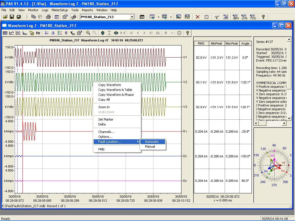
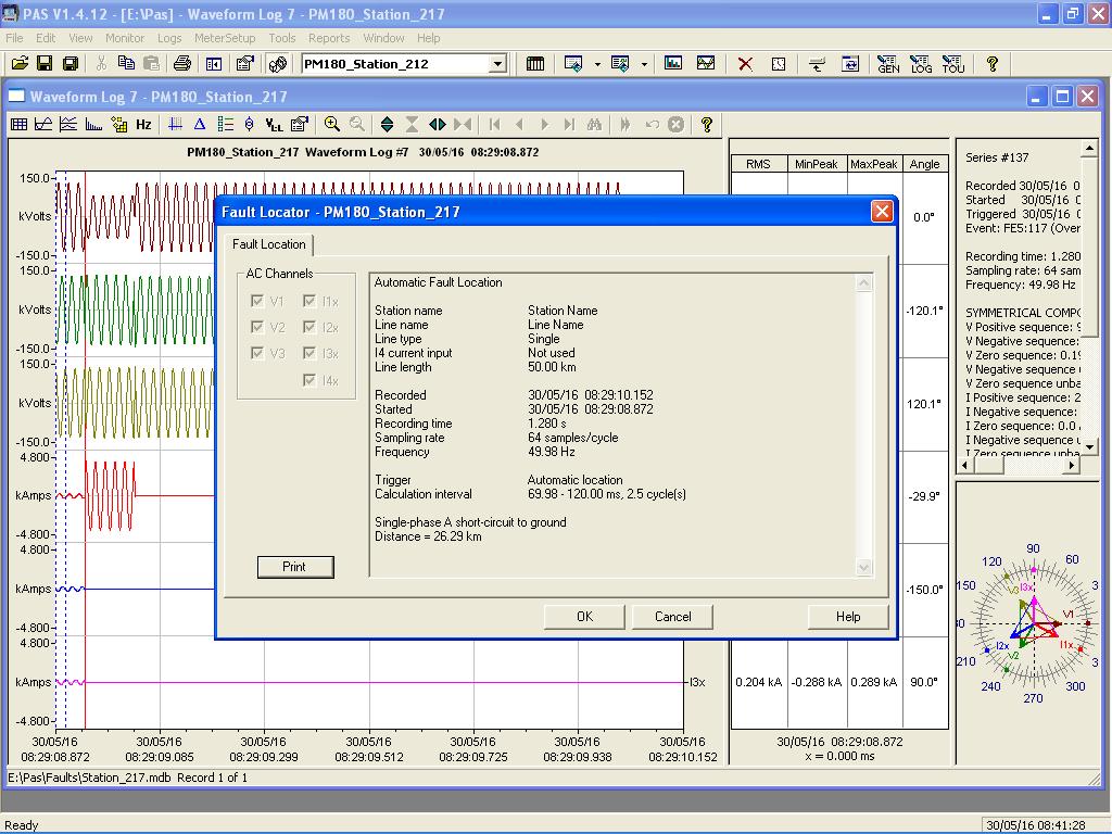
16 4 Using the Off-line Fault Locator 4.1 Single-ended Fault Location For off-line single-ended fault location: 1. Retrieve the fault waveform log file from your device as shown in section Getting Recorded Data above. 2. Select Open in the File menu, point to the database with the uploaded data and double click on the waveform log table on the right pane. 3. Select a fault waveform for which you want to calculate the fault distance. See Viewing Waveforms in the PM180 Operation Manual for more information on viewing options. 4. Click on the waveform window with the right mouse button, point to Fault Location and select Automatic. 5. If you wish to manually locate the fault window for distance calculations, point with the mouse to the left dashed marker line and drag it to the place where the window is to begin, then click on the waveform with the right mouse button, point to Fault Location and select Manual. The distance calculation results are indicated as shown in the picture below. Click on Print if you wish to get a printed copy of the results. 16
17 17

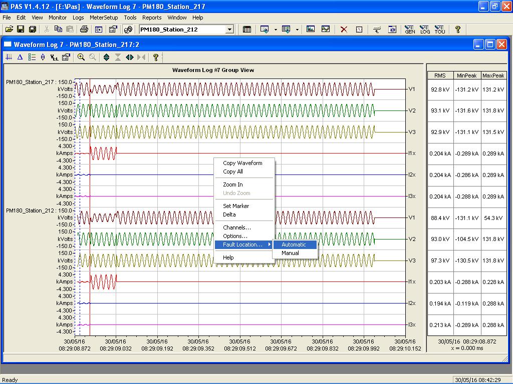
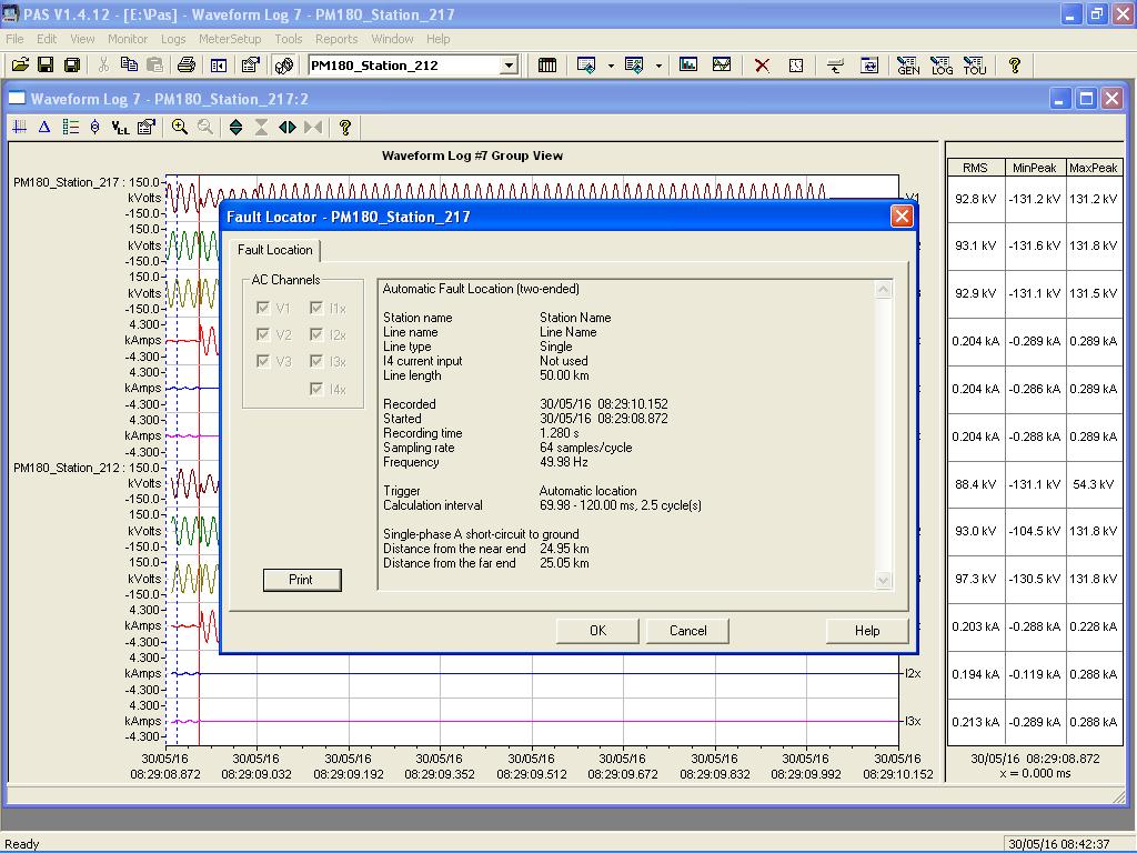
18 4.2 Two-ended Fault Location For two-ended fault location: 1. Retrieve the fault waveform log files from both devices located on two sides of the power line as shown in section Getting Recorded Data above. Put both databases with the retrieved data to the same folder. 2. Select Open in the File menu, point to one of the databases with the uploaded data and double click on the waveform log table on the right pane. 3. Select a fault waveform for which you want to calculate the fault distance. See Viewing Waveforms in the PM180 Operation Manual for more information on viewing options. 4. Click on the Multi-site View icon on the PAS toolbar (surrounded by red circle in the picture below). PAS scans through the databases for waveforms that match in time with the selected waveform and shows a list of events for which such a match is found. 5. Check the two-sided waveforms to be uses for distance calculations. You can also select the waveform channels you want to view for each site by clicking the button on the right to the site. An example of two synchronized waveforms is shown in the picture below. 6. Click on the waveform with the right mouse button, point to Fault Location and select Automatic. 7. If you wish to manually locate the fault window for distance calculations, point with the mouse to the left dashed marker line and drag it to the place where the window is to begin, then click on the waveform with the right mouse button, point to Fault Location and select Manual. The distance calculation results are indicated as shown in the picture below. Click on Print if you wish to get a printed copy of the results. 18
19 19
Ansoft Designer Tutorial ECE 584 October, 2004
 Ansoft Designer Tutorial ECE 584 October, 2004 This tutorial will serve as an introduction to the Ansoft Designer Microwave CAD package by stepping through a simple design problem. Please note that there
ArbStudio Triggers. Using Both Input & Output Trigger With ArbStudio APPLICATION BRIEF LAB912
 ArbStudio Triggers Using Both Input & Output Trigger With ArbStudio APPLICATION BRIEF LAB912 January 26, 2012 Summary ArbStudio has provision for outputting triggers synchronous with the output waveforms
IX Feb Operation Guide. Sequence Creation and Control Software SD011-PCR-LE. Wavy for PCR-LE. Ver. 5.5x
 IX000693 Feb. 015 Operation Guide Sequence Creation and Control Software SD011-PCR-LE Wavy for PCR-LE Ver. 5.5x About This Guide This PDF version of the operation guide is provided so that you can print
RICOH Stereo Camera Software R-Stereo-GigE-Calibration
 RICOH Stereo Camera Software R-Stereo-GigE-Calibration User's Guide RICOH Industrial Solutions Inc. 1/18 Contents 1. FUNCTION OVERVIEW... 3 1.1 Operating Environment... 3 2. OPERATING PROCEDURES... 4 3.
CCG Referral App - Northern Ireland
 CCG Referral App - Northern Ireland For practices in Northern Ireland who use the Referral Screen supplied by the CCG, the way you access the screen has been updated. A Vision App has been created to enable
Reviewing Your Tax Return In Your Portal
 Reviewing Your Tax Return In Your Portal 1. Go to our website www.franklinincpa.com and click on the link at the bottom left of the screen for Client Connect. a. This link will take you to the login screen
9/2/2013 Excellent ID. Operational Manual eskan SADL handheld scanner
 9/2/2013 Excellent ID Operational Manual eskan SADL handheld scanner Thank You! We are grateful you chose Excellent ID for your SADL scanner needs. We believe this easy-to-use scanner will provide dependable
Quick Start Guide for the PULSE PROFILING APPLICATION
 Quick Start Guide for the PULSE PROFILING APPLICATION MODEL LB480A Revision: Preliminary 02/05/09 1 1. Introduction This document provides information to install and quickly start using your PowerSensor+.
LAB 8: Activity P52: LRC Circuit
 LAB 8: Activity P52: LRC Circuit Equipment: Voltage Sensor 1 Multimeter 1 Patch Cords 2 AC/DC Electronics Lab (100 μf capacitor; 10 Ω resistor; Inductor Coil; Iron core; 5 inch wire lead) The purpose of
Context-Aware Planning and Verification
 7 CHAPTER This chapter describes a number of tools and configurations that can be used to enhance the location accuracy of elements (clients, tags, rogue clients, and rogue access points) within an indoor
Activity P52: LRC Circuit (Voltage Sensor)
") Activity P52: LRC Circuit (Voltage Sensor) Concept DataStudio ScienceWorkshop (Mac) ScienceWorkshop (Win) AC circuits P52 LRC Circuit.DS (See end of activity) (See end of activity) Equipment Needed Qty
Activity P52: LRC Circuit (Voltage Sensor) Concept DataStudio ScienceWorkshop (Mac) ScienceWorkshop (Win) AC circuits P52 LRC Circuit.DS (See end of activity) (See end of activity) Equipment Needed Qty
Version 9.1 SmartPTT Monitoring
 Version 9.1 SmartPTT Monitoring December 2016 Table of Contents Table of Contents 1.1 Introduction 2 1.2 Installation of the SmartPTT software 2 1.3 General SmartPTT Radioserver Configuration 6 1.4 SmartPTT
UCP-Config Program Version: 3.28 HG A
 Program Description HG 76342-A UCP-Config Program Version: 3.28 HG 76342-A English, Revision 01 Dev. by: C.M. Date: 28.01.2014 Author(s): RAD Götting KG, Celler Str. 5, D-31275 Lehrte - Röddensen (Germany),
Metaphase ULC-2. Technologies ULC. Metaphase. Technologies Version 7.X August 2015 USER MANUAL. metaphase-tech.com. pg. 1
 ULC Version 7.X August 2015 USER MANUAL pg. 1 Overview Universal LED Controller () provides independent true constant-current or voltage control of two LED loads from 0.02 to 4 Amps continuous (DC) with
Submittals Quick Reference Guide
 This topic provides a reference for the Project Center Submittals activity center. Purpose The Submittals activity center in Newforma Contract Management enables you to effectively log submittals and track
LincView OPC USER GUIDE. Enhanced Diagnostics Utility INDUSTRIAL DATA COMMUNICATIONS
 USER GUIDE INDUSTRIAL DATA COMMUNICATIONS LincView OPC Enhanced Diagnostics Utility It is essential that all instructions contained in the User Guide are followed precisely to ensure proper operation of
INSTRUCTION MANUAL IP REMOTE CONTROL SOFTWARE RS-BA1
 INSTRUCTION MANUAL IP REMOTE CONTROL SOFTWARE RS-BA FOREWORD Thank you for purchasing the RS-BA. The RS-BA is designed to remotely control an Icom radio through a network. This instruction manual contains
Scorer with BridgePads Quick Guide to Teams Scoring
 December 2013, Scorer 14 Scorer with BridgePads Quick Guide to Teams Scoring These instructions a short guide to Teams scoring. Only the most common functions are covered. For details on more advanced
WEB I/O. Wireless On/Off Control USER MANUAL
 Wireless On/Off Control Technical Support: Email: support@encomwireless.com Toll Free: 1 800 617 3487 Worldwide: (403) 230 1122 Fax: (403) 276 9575 Web: www.encomwireless.com Warnings and Precautions Warnings
uiulearn TUTORIAL INTEGRATIONS> HOW TO USE PANOPTO (STUDENT)
") uiulearn TUTORIAL INTEGRATIONS> HOW TO USE PANOPTO (STUDENT) This tutorial covers how to record a Panopto video for your course. IN ORDER TO DO THIS, YOUR INSTRUCTOR MUST COMPLETE SEVERAL STEPS TO ALLOW
uiulearn TUTORIAL INTEGRATIONS> HOW TO USE PANOPTO (STUDENT) This tutorial covers how to record a Panopto video for your course. IN ORDER TO DO THIS, YOUR INSTRUCTOR MUST COMPLETE SEVERAL STEPS TO ALLOW
Loss Compensation in 50 Series SCADA Meters. Loss Compensation in 50 Series SCADA Meters. Bitronics D/3 Orion. Loss Compensation in 50 Series 1
 Bitronics D/3 Orion in 50 Series 1 This page intentionally left blank. 2 in 50 Series Objective: Calculate the settings required to configure an M650 so its power and energy measurements represent the
Digital Fault Recorder Deployment at HVDC Converter Stations
 Digital Fault Recorder Deployment at HVDC Converter Stations On line continuous monitoring at HVDC Converter Stations is an important asset in determining overall system performance and an essential diagnostic
FLIR Tools for PC 7/21/2016
 FLIR Tools for PC 7/21/2016 1 2 Tools+ is an upgrade that adds the ability to create Microsoft Word templates and reports, create radiometric panorama images, and record sequences from compatible USB and
Revision Date: 6/6/2013. Quick Start Guide
 Revision Date: 6/6/2013 Quick Start Guide Important Notice Copyright 2013Frontline Test Equipment. All rights reserved. i Important Notice Table of Contents Purpose 1 Minimum Hardware Requirements 1 Internet
BG-Map Mapping the world one plant at a time
 BG-Map Mapping the world one plant at a time Total Station Interface Users Manual Total Station Interface version 5.8 Copyright 1992-2015 Glicksman Associates, Inc. All rights reserved. No part of this
AEP s 765kV Transmission Line Model Validation for Short Circuit and System Studies. T. YANG, Q. QIU, Z. CAMPBELL American Electric Power USA
 1, rue d Artois, F-75008 PARI CIGRE U National Committee http : //www.cigre.org 015 Grid of the Future ymposium AEP s 765kV Transmission Line Model Validation for hort Circuit and ystem tudies T. YANG,
EOS 80D (W) Wireless Function Instruction Manual ENGLISH INSTRUCTION MANUAL
 Wireless Function Instruction Manual ENGLISH INSTRUCTION MANUAL") EOS 80D (W) Wireless Function Instruction Manual ENGLISH INSTRUCTION MANUAL Introduction What You Can Do Using the Wireless Functions This camera s wireless functions let you perform a range of tasks wirelessly,
EOS 80D (W) Wireless Function Instruction Manual ENGLISH INSTRUCTION MANUAL Introduction What You Can Do Using the Wireless Functions This camera s wireless functions let you perform a range of tasks wirelessly,
DOUBLE-ENDED FAULT LOCATORS
 The InterNational Electrical Testing Association Journal FEATURE END-TO-END TESTING OF DOUBLE-ENDED FAULT LOCATORS BY STEVE TURNER, Beckwith Electric Company, Inc.. www.netaworld.org FOR HIGH VOLTAGE,
ULTRA RAPID POWER QUALITY ANALYZER
 ULTRA RAPID POWER QUALITY ANALYZER Ultra rapid (cycle by cycle) advanced electrical network analysis Complete network harmonics analysis, up to 63 rd harmonic High visibility, 5 graphic LCD screen with
Nova Full-Screen Calibration System
 Nova Full-Screen Calibration System Version: 5.0 1 Preparation Before the Calibration 1 Preparation Before the Calibration 1.1 Description of Operating Environments Full-screen calibration, which is used
LESSONS Lesson 1. Microcontrollers and SBCs. The Big Idea: Lesson 1: Microcontrollers and SBCs. Background: What, precisely, is computer science?
 LESSONS Lesson Lesson : Microcontrollers and SBCs Microcontrollers and SBCs The Big Idea: This book is about computer science. It is not about the Arduino, the C programming language, electronic components,
Using the S5U13781R01C100 Shield Graphics Library with Atmel Studio
 Using the S5U13781R01C100 Shield Graphics Library with Atmel Studio Document Number: X94A-B-002-01 Status: Revision 1.0 Issue Date: 2015/07/30 SEIKO EPSON CORPORATION Rev. 1.0 Page 2 NOTICE No part of
Metaphase ULC-2. Technologies ULC. Metaphase. Technologies Version 6.2 June 12, 2013 USER MANUAL. metaphase-tech.com. pg. 1
 ULC Version 6.2 June 12, 2013 USER MANUAL pg. 1 Overview Universal LED Controller () provides independent true constant-current or voltage control of two LED loads from 0.02 to 4 Amps continuous (DC) with
ACCU-GOLD QUICK START MANUAL
 ACCU-GOLD Now includes support for the light sensor (AGLS) and Accu Gold+ digitizers and sensors (AGDM+, AGMS DM+) Nomenclature AGDM Accu-Gold Digitizer Module RGDM Rapid-Gold Digitizer Module RGDM-MA
Eighth Annual QUIKLOOK Users Group Meeting
 Eighth Annual QUIKLOOK Users Group Meeting Marion, MA August 20 & 21st, 2014 Eric Solla QUIKLOOK Product Manager Quiklook Software Update Version 2013.256 Released August 2013 Quiklook II Version 2013.309
TEK-TROL HART GATEWAY SOFTWARE. Operating Instruction Manual.
 TEK-TROL HART GATEWAY SOFTWARE Operating Instruction Manual www.tek-trol.com Table of Contents 1 Getting Started... 2 1.1 Setup Procedure... 2 1.2 Quick Setup Guide for Radar Sensors... 10 2 Level device
Excel Lab 2: Plots of Data Sets
 Excel Lab 2: Plots of Data Sets Excel makes it very easy for the scientist to visualize a data set. In this assignment, we learn how to produce various plots of data sets. Open a new Excel workbook, and
EE 210 Lab Exercise #3 Introduction to PSPICE
 EE 210 Lab Exercise #3 Introduction to PSPICE Appending 4 in your Textbook contains a short tutorial on PSPICE. Additional information, tutorials and a demo version of PSPICE can be found at the manufacturer
Using Signal Studio Waveform Licenses. Procedure
 Using Signal Studio Waveform Licenses Procedure This Document This document describes how to: Use the Signal Studio software to configure, generate, and download waveform files to your instrument Play
INTRODUCTION TO DATA STUDIO
 1 INTRODUCTION TO DATA STUDIO PART I: FAMILIARIZATION OBJECTIVE To become familiar with the operation of the Passport/Xplorer digital instruments and the DataStudio software. INTRODUCTION We will use the
ELE3310 Basic Electromagnetics Lab Session 1
 ELE3310 Basic Electromagnetics Lab Session 1 Gao Xin By modifying CST MICROWAVE STUDIO 2006 tutorials Geometric Construction and Solver Settings Introduction and Model Dimensions In this tutorial you will
g GE POWER MANAGEMENT
 745 FREQUENTLY ASKED QUESTIONS 1 I get a communication error with the relay when I try to store a setpoint. This error can occur for several different reasons. First of all, verify that the address is
Go Daddy Online Photo Filer
 Getting Started and User Guide Discover an easier way to share, print and manage your photos online! Online Photo Filer gives you an online photo album site for sharing photos, as well as easy-to-use editing
TurboVUi Solo. User Guide. For Version 6 Software Document # S Please check the accompanying CD for a newer version of this document
 TurboVUi Solo For Version 6 Software Document # S2-61432-604 Please check the accompanying CD for a newer version of this document Remote Virtual User Interface For MOTOTRBO Professional Digital 2-Way
Instruction Manual ABM HART Gateway Software. Instruction Manual Revision A.1
 Instruction Manual ABM HART Gateway Software Instruction Manual Revision A.1 Table of Contents Section 1: Getting Started... 3 1.1 Setup Procedure... 3 1.2 Quick Setup Guide for Ultrasonic Sensors... 11
g. Click once on the left vertical line of the rectangle.
 This drawing will require you to a model of a truck as a Solidworks Part. Please be sure to read the directions carefully before constructing the truck in Solidworks. Before submitting you will be required
Excel Tool: Plots of Data Sets
 Excel Tool: Plots of Data Sets Excel makes it very easy for the scientist to visualize a data set. In this assignment, we learn how to produce various plots of data sets. Open a new Excel workbook, and
Keysight MOI for MIPI D-PHY Conformance Tests Revision Oct, 2014
 Revision 1.10 10-Oct, 2014 Keysight Method of Implementation (MOI) for MIPI D-PHY Conformance Tests Using Keysight E5071C ENA Network Analyzer Option TDR 1 Table of Contents 1. Modification Record... 4
Configuration Guide. Version 8.3
 Capacity Plus Configuration Guide Version 8.3 Table of Contents 1 Table of Contents 1 Introduction 2 2 Brief Information on Use of Control Stations 4 3 6 3.1 Programming Repeter 7 3.1.1 Master Repeater
Phone Web
 APRIL 13, 2018 Page 1 of 5 Overview Crown CDi DriveCore power amplifiers can be configured for use with Revel Extreme Climate L41XC, L42XC, and L12XC Landscape series loudspeakers. The speaker tuning settings
8000 SERIES PRECISION MULTIMETER VERIFICATION AND ADJUSTMENT GUIDE
 8000 SERIES PRECISION MULTIMETER VERIFICATION AND ADJUSTMENT GUIDE TRANSMILLE LTD. Version 1.1 : Apr 2015 TABLE OF CONTENTS PREPARING FOR CALIBRATION... 4 INTRODUCTION... 4 CALIBRATION INTERVAL SELECTION...
Hytera. PD41X Patrol Management System. Installation and Configuration Guide
 Hytera PD41X Patrol Management System Installation and Configuration Guide Documentation Version: 01 Release Date: 03-2015 Copyright Information Hytera is the trademark or registered trademark of Hytera
Genesis Channel Manager
 Genesis Channel Manager VPI 160 Camino Ruiz, Camarillo, CA 93012-6700 (Voice) 800-200-5430 805-389-5200 (Fax) 805-389-5202 www.vpi-corp.com 1 Contents Genesis Channel Manager -----------------------------------------------------------------------------------------------------------------
ZONESCAN net Version 1.4.0
 ZONESCAN net.0 REV 1. JW ZONESCAN net 2 / 56 Table of Contents 1 Introduction... 5 1.1 Purpose and field of use of the software... 5 1.2 Software functionality... 5 1.3 Function description... 6 1.3.1
GotSoccer works well with and recommends using Internet Explorer, Safari and Google Chrome.
 Cal North CCSL Member Clubs Internet Browser Notice: GotSoccer works well with and recommends using Internet Explorer, Safari and Google Chrome. Some GotSoccer features will not work with Firefox Using
Teaching Distance Relay Using Matlab/Simulink Graphical User Interface
 Available online at www.sciencedirect.com Procedia Engineering 53 ( 2013 ) 264 270 Malaysian Technical Universities Conference on Engineering & Technology 2012, MUCET 2012 Part 1 - Electronic and Electrical
scancontrol Configuration Tools 5.1 Instruction Manual
 scancontrol Configuration Tools 5.1 Instruction Manual MICRO-EPSILON MESSTECHNIK GmbH & Co. KG Königbacher Straße 15 D-94496 Ortenburg / Germany Tel. +49 (0) 8542 /168-0 Fax +49 (0) 8542 /168-90 e-mail:
DPA602 1/7. Multi-Channel Network Amplifier. General Description. Features. Applications. AtlasIED.com. DPA602 Front. DPA602 Back
 1/7 DPA602 Multi-Channel Network Amplifier Features Configurations 2 x 300 Watt 70V / 100V (Factory Default) 4 x 150 Watt @ 4Ω 1 x 300 Watt 70V / 100V & 2 x 150 Watt @ 4Ω No Computer Required to Operate
Basic Recording. Start --> Programs --> Panopto --> Panopto Recorder. Logging In
 Basic Recording Logging In Presenters are able to log into the Recorder with their credentials and record video, audio, PowerPoint presentations and also add Screen Capture functionality. NOTE: If using
Agilent MOI for MIPI D-PHY Conformance Tests Revision 1.00 Dec-1, 2011
 Revision 1.00 Dec-1, 2011 Agilent Method of Implementation (MOI) for MIPI D-PHY Conformance Tests Using Agilent E5071C ENA Network Analyzer Option TDR 1 Table of Contents 1. Modification Record... 4 2.
Applications Note. Successfully using the Model 8000 NERO dental x-ray machine timer performance. max to evaluate
 Successfully using the Model 8000 NERO dental x-ray machine timer performance max to evaluate Information in this article applies to Model 8000 NERO max firmware release 2.3 or higher. Introduction The
IB Nov User s Manual. KFM Series Application Software. FCTester. Ver. 1.1
 IB011511 Nov. 2006 User s Manual KFM Series Application Software FCTester Ver. 1.1 Use of This Manual Please read through and understand this User s Manual before operating the product. After reading,
VOLTAGE. User Guide ACCESSORIES. External Sensor DT140. for MicroLog EC600 and EC V ±0.05V ±3% (before calibration)
") External Sensor VOLTAGE DT140 Range: Resolution: Accuracy: Input impedance: Calibration: OV protection: 0-10V ±0.05V ±3% (before calibration) 3MΩ 2 calibration points ±30V ACCESSORIES User Guide for MicroLog
External Sensor VOLTAGE DT140 Range: Resolution: Accuracy: Input impedance: Calibration: OV protection: 0-10V ±0.05V ±3% (before calibration) 3MΩ 2 calibration points ±30V ACCESSORIES User Guide for MicroLog
VTube-LASER Quick Start Guide
 VTube-LASER Quick Start Guide This guide shows how to import a STEP file and then MEASURE and qualify demo tube 4 using the standard UNISCAN method of measuring. The steps in this workflow are from version
ChordPolyPad Midi Chords Player iphone, ipad Laurent Colson
 ChordPolyPad 1 ChordPolyPad Midi Chords Player iphone, ipad Laurent Colson 1. ipad overview... 2 2. iphone overview... 3 3. Preset manager... 4 4. Save preset... 5 5. Midi... 6 6. Midi setup... 7 7. Pads...
CURRENT. User Guide ACCESSORIES. External Sensor DT139. for MicroLog EC600 and EC mA ±0.1mA ±3% (before calibration)
") External Sensor CURRENT DT139 Range: Resolution: Accuracy: Input impedance: Calibration: OV protection: 0-20mA ±0.1mA ±3% (before calibration) ~170Ω 2 calibration points ±55mA ACCESSORIES User Guide for
External Sensor CURRENT DT139 Range: Resolution: Accuracy: Input impedance: Calibration: OV protection: 0-20mA ±0.1mA ±3% (before calibration) ~170Ω 2 calibration points ±55mA ACCESSORIES User Guide for
Bluetooth Based IOT through Arduino
 1 Bluetooth Based IOT through Arduino G V V Sharma Fig. 1: Breadboard 1 Measuring the resistance Problem 1. Connect the 5V pin of the Arduino to an extreme pin of the Breadboard shown in Fig. 1. Let this
BANTAM INSTRUMENTS SOFTWARE USER S MANUAL MIL-STD-461E PRE-COMPLIANCE MEASUREMENT SYSTEM MODEL EMC-461. Model EMC-461 Software User s Manual
 BANTAM INSTRUMENTS MIL-STD-461E PRE-COMPLIANCE MEASUREMENT SYSTEM MODEL EMC-461 SOFTWARE USER S MANUAL MIL-STD-461E PRE-COMPLIANCE MEASUREMENT SYSTEM MODEL EMC-461 Software User s Manual BANTAM INSTRUMENTS
Modular Metering System ModbusTCP Communications Manual
 Modular Metering System Manual Revision 7 Published October 2016 Northern Design Metering Solutions Modular Metering System ModbusTCP 1 Description The multicube modular electricity metering system simultaneously
Estimation of Fault Resistance from Fault Recording Data. Daniel Wong & Michael Tong 2014-November-5
 Estimation of Fault Resistance from Fault Recording Data Daniel Wong & Michael Tong 2014-November-5 Agenda Project Background & Introduction Fault Resistance & Effect Estimation Algorithm Estimation Results
Teledyne PDS. Monopile Placement - Laser scan position. Version March 2017
 Monopile Placement - Laser scan position Teledyne PDS Version 2.3.1 March 2017 Teledyne RESON B.V. Stuttgartstraat 42-44 3047 AS Rotterdam The Netherlands Tel.: +31 (0)10 245 15 00 www.teledyne-reson.com
POWER QUALITY AND REVENUE METER EM720/EM720T. Operation Manual. BG0451 Rev. A1
 POWER QUALITY AND REVENUE METER EM720/EM720T Operation Manual BG0451 Rev. A1 LIMITED WARRANTY The manufacturer offers the customer a 24-month functional warranty on the instrument for faulty workmanship
Performance Evaluation of Traveling Wave Fault Locator for a 220kV Hoa Khanh-Thanh My Transmission Line
 Engineering, Technology & Applied Science Research Vol. 8, No. 4, 2018, 3243-3248 3243 Performance Evaluation of Traveling Wave Fault Locator for a 220kV Hoa Khanh-Thanh My Transmission Line Kim Hung Le
DNP V3.00 LEVEL 2 Protocol Assignments
 Electro Industries / GaugeTech "The Leader in Power Monitoring and " DNP V3.00 LEVEL 2 Protocol Assignments For Nexus 1252, 1262, 1272 and 1500 Power Monitors Doc # E107709 Revision 1.1, 20 Electro Industries/GaugeTech
Geometer s Sketchpad Version 4
 Geometer s Sketchpad Version 4 For PC Name: Date: INVESTIGATION: The Pythagorean Theorem Directions: Use the steps below to lead you through the investigation. After each step, be sure to click in the
Setup and Operation of Local and Remote PhaseID System Base Stations
 Setup and Operation of Local and Remote PhaseID System Base Stations 1 Setup and Operation of Local and Remote PhaseID System Base Stations Introduction The Origo PhaseID System identifies phase attributes
External Source Control
 External Source Control X-Series Signal Analyzers Option ESC DEMO GUIDE Introduction External source control for X-Series signal analyzers (Option ESC) allows the Keysight PXA, MXA, EXA, and CXA to control
Learning Guide. ASR Automated Systems Research Inc. # Douglas Crescent, Langley, BC. V3A 4B6. Fax:
 Learning Guide ASR Automated Systems Research Inc. #1 20461 Douglas Crescent, Langley, BC. V3A 4B6 Toll free: 1-800-818-2051 e-mail: support@asrsoft.com Fax: 604-539-1334 www.asrsoft.com Copyright 1991-2013
for Solidworks TRAINING GUIDE LESSON-9-CAD
 for Solidworks TRAINING GUIDE LESSON-9-CAD Mastercam for SolidWorks Training Guide Objectives You will create the geometry for SolidWorks-Lesson-9 using SolidWorks 3D CAD software. You will be working
How to make a list sweep measurement
 How to make a list sweep measurement This material shows how to perform a list sweep measurement through an example of the Photovoltaic Cell IV measurement. Figure 1 illustrates the connection and condition
Overview. The Game Idea
 Page 1 of 19 Overview Even though GameMaker:Studio is easy to use, getting the hang of it can be a bit difficult at first, especially if you have had no prior experience of programming. This tutorial is
Step 1: Set up the variables AB Design. Use the top cells to label the variables that will be displayed on the X and Y axes of the graph
 Step 1: Set up the variables AB Design Use the top cells to label the variables that will be displayed on the X and Y axes of the graph Step 1: Set up the variables X axis for AB Design Enter X axis label
Setup and Walk Through Guide Orion for Clubs Orion at Home
 Setup and Walk Through Guide Orion for Clubs Orion at Home Shooter s Technology LLC Copyright by Shooter s Technology LLC, All Rights Reserved Version 2.5 September 14, 2018 Welcome to the Orion Scoring
Motor-CAD Brushless PM motor Combined electromagnetic and thermal model (February 2015)
") Motor-CAD Brushless PM motor Combined electromagnetic and thermal model (February 2015) Description The Motor-CAD allows the machine performance, losses and temperatures to be calculated for a BPM machine.
Motor-CAD Brushless PM motor Combined electromagnetic and thermal model (February 2015) Description The Motor-CAD allows the machine performance, losses and temperatures to be calculated for a BPM machine.
Importing and processing gel images
 BioNumerics Tutorial: Importing and processing gel images 1 Aim Comprehensive tools for the processing of electrophoresis fingerprints, both from slab gels and capillary sequencers are incorporated into
SourceXpress Waveform Creation Application Printable Help Document
 xx ZZZ SourceXpress Waveform Creation Application Printable Help Document *P077114504* 077-1145-04 ZZZ SourceXpress Waveform Creation Application Printable Help Document www.tek.com 077-1145-04 Copyright
AXIS Fence Guard. User Manual
 User Manual About This Document This manual is intended for administrators and users of the application AXIS Fence Guard version 1.0. Later versions of this document will be posted to Axis website, as
Shenzhen ATC Technology CO.,LTD ATC. A-1 Serial Remote I/O Module. User Manual. V1.13 Edit:2018/01/
 ATC A-1 Serial Remote I/O Module User Manual V1.13 Edit:2018/01/30-1 - Catalogue 1.The introduction of Modbus protocol...- 3-1.1 Modbus protocol master-slave response process... - 3-1.2 Modbus register
ISONIC PA AUT Spiral Scan Inspection of Tubular Parts Operating Manual and Inspection Procedure Rev 1.00 Sonotron NDT
 ISONIC PA AUT Spiral Scan Inspection of Tubular Parts Operating Manual and Inspection Procedure Rev 1.00 Sonotron NDT General ISONIC PA AUT Spiral Scan Inspection Application was designed on the platform
Temperature Monitoring and Fan Control with Platform Manager 2
 August 2013 Introduction Technical Note TN1278 The Platform Manager 2 is a fast-reacting, programmable logic based hardware management controller. Platform Manager 2 is an integrated solution combining
1. What is SENSE Batch
 1. What is SENSE Batch 1.1. Introduction SENSE Batch is processing software for thermal images and sequences. It is a modern software which automates repetitive tasks with thermal images. The most important
Impedance Transformation with Transmission Lines
 Impedance Transformation with Transmission Lines Software Installation and Operation Manual Don Cochran WAØJOW 21826 Gardner Rd. Spring Hill, KS 66083 (913) 856-4075 Manual Revision 1 Page 1 Table of Contents
This tutorial will guide you through the process of adding basic ambient sound to a Level.
 Tutorial: Adding Ambience to a Level This tutorial will guide you through the process of adding basic ambient sound to a Level. You will learn how to do the following: 1. Organize audio objects with a
SmartPTT. Indoor Positioning Service
 SmartPTT Indoor Positioning Service October 2018 Indoor Tracking in SmartPTT Configurator Indoor Tracking in SmartPTT Configurator Big organizations with huge premises require constant control over their
Version 9.1 SmartPTT Enterprise. Installation & Configuration Guide
 Version 9.1 SmartPTT Enterprise December 2016 Table of Contents Table of Contents 1.1 Introduction 3 1.2 Installation of the SmartPTT software 3 1.3 General SmartPTT Radioserver Configuration 7 1.4 SmartPTT
Engineering Technology
 Engineering Technology Introduction to Parametric Modelling Engineering Technology 1 See Saw Exercise Part 1 Base Commands used New Part This lesson includes Sketching, Extruded Boss/Base, Hole Wizard,
GUIDE TO GAME LOBBY FOR STRAT-O-MATIC COMPUTER BASEBALL By Jack Mitchell
 GUIDE TO GAME LOBBY FOR STRAT-O-MATIC COMPUTER BASEBALL By Jack Mitchell Game Lobby (also referred to as NetPlay) is a valuable feature of Strat-O-Matic Computer Baseball that serves three purposes: 1.
CREATING (AB) SINGLE- SUBJECT DESIGN GRAPHS IN MICROSOFT EXCEL Lets try to graph this data
 SINGLE- SUBJECT DESIGN GRAPHS IN MICROSOFT EXCEL Lets try to graph this data") CREATING (AB) SINGLE- SUBJECT DESIGN GRAPHS IN MICROSOFT EXCEL 2003 Lets try to graph this data Date Baseline Data Date NCR (intervention) 11/10 11/11 11/12 11/13 2 3 3 1 11/15 11/16 11/17 11/18 3 3 2
CREATING (AB) SINGLE- SUBJECT DESIGN GRAPHS IN MICROSOFT EXCEL 2003 Lets try to graph this data Date Baseline Data Date NCR (intervention) 11/10 11/11 11/12 11/13 2 3 3 1 11/15 11/16 11/17 11/18 3 3 2
Implementation and Evaluation a SIMULINK Model of a Distance Relay in MATLAB/SIMULINK
 Implementation and Evaluation a SIMULINK Model of a Distance Relay in MATLAB/SIMULINK Omar G. Mrehel Hassan B. Elfetori AbdAllah O. Hawal Electrical and Electronic Dept. Operation Department Electrical
About the DSR Dropout, Surge, Ripple Simulator and AC/DC Voltage Source
 About the DSR 100-15 Dropout, Surge, Ripple Simulator and AC/DC Voltage Source Congratulations on your purchase of a DSR 100-15 AE Techron dropout, surge, ripple simulator and AC/DC voltage source. The