Switched Mode Power Supply Measurements
|
|
|
- Osborne Knight
- 6 years ago
- Views:
Transcription


1 Power Analysis 1

2 Switched Mode Power Supply Measurements AC Input Power measurements Safe operating area Harmonics and compliance Efficiency Switching Transistor Losses Measurement challenges Transformer B-H curve Dynamic Control Loop Step load and start up behavior Output Ripple

3 AC Input Line Power and Harmonics AC In + + DC Out PWM Controller Feedback

4 Line Voltage Line Current Line Power RMS line voltage, RMS line current, real power, apparent power, power factor and crest factor

5 Line Harmonic Analysis Line harmonics can be measured against compliance standards like EN

6 Power supply efficiency measurement


7 Safe Operating Area Mask Testing
8 Switched-Mode Power Supply AC In + + DC Out DC AC PWM Controller Feedback The measurements we will talk about here are useful for any inverter based power conversion device

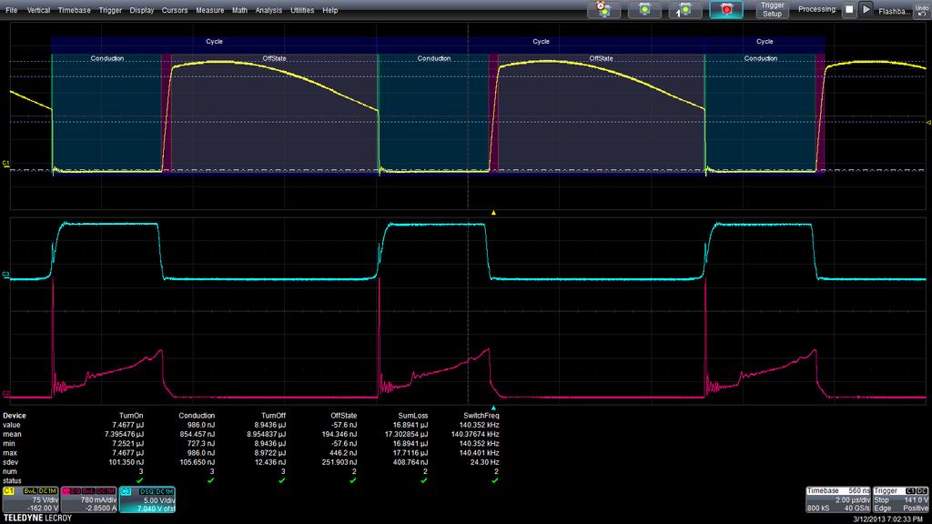
9 Energy Loss Loss displayed in Joules

10 Power Loss Loss displayed in Watts Power = Energy / Time
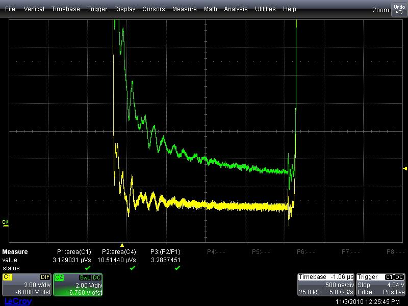
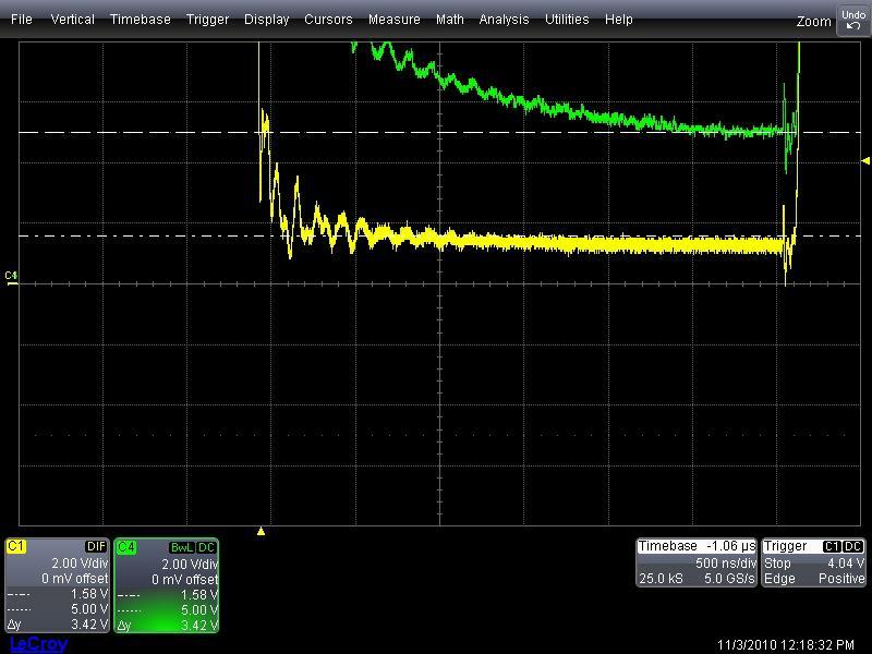
11 Conduction Loss Measurement Challenge Although the peak to peak waveform may be hundreds of volts, during the conduction stage the voltage is close to zero. Measuring the conduction loss or dynamic on resistance is a challenge due to the limited dynamic range of the oscilloscope

12 Solution 1: Overdriving the Signal Differential probe response is very slow to stabilize, and never reaches the correct saturation voltage level Differential amplifier response rapidly stabilizes and reaches the correct saturation voltage level Differential Amplifier Differential Probe


13 Using Differential Amplifier for Saturation Measurements CMRR 100,000:1 Overdrive recovery 400 V to 100 mv <100 ns Precision Offset Generator 0.5% DA1855A Differential Amplifier Differential Amplifier connected to oscilloscope
14
15
16 Using High Definition Oscilloscopes 12-Bit Capture 8-Bit Capture

17 Using High Definition Scope with High Accuracy Probes 12-Bit Capture, 1% accuracy Probe 12-Bit Capture, Standard Probe


18 Example Hardware Configuration Voltage and current probes to match the accuracy of HDO scopes High voltage differential probes with high accuracy and high CMRR. Current probes offer high accuracy and low noise. CP030A and CP031A HVD3102 and HVD3106

19 Rds On Resistance Measurement Overdrive recovery of differential amplifier and high resolution oscilloscope combination

20 Eliminating Sources of Error DC Offsets, Deskew Before making detailed device loss measurements, fine adjust to eliminate DC offset errors and scope probe propagation delay differences

21 Two Ways to Fine Adjust Current Probe DC Offset During Off-state, utilize Math integral function and adjust for zero slope Utilize Power Analyzer s automatic calculation of Off-State Losses and fine adjust to zero


22 Deskewing Voltage and Current Probes Use a deskew calibration source, with V and I coincident edges, to remove propagation delay differences between voltage and current probes Line up the knee of the curve to deskew for power measurement


23 Sources of Error Skew Between Voltage and Current Probes Timing skew between voltage and current probes results in measurement error Device turn-off transition loss, V x I, is properly measured at 7.88 nj of energy versus nj without proper deskew
24 Switched-Mode Power Supply AC In + + DC Out PWM Controller Feedback The transformer provides isolation between the power supply input and output

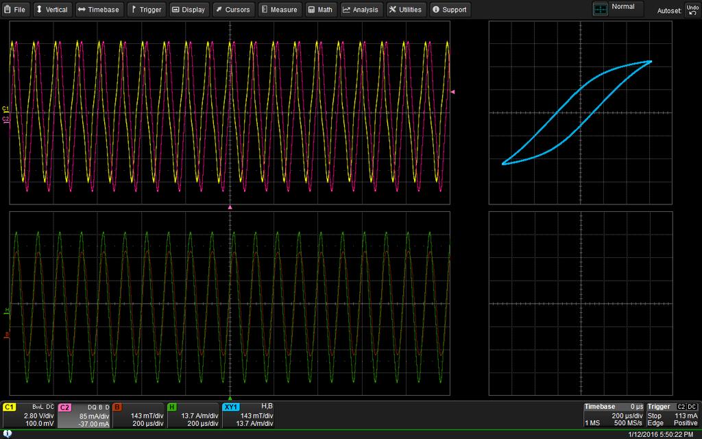
25 Power Analyzer BH Curve

26 Power Analyzer BH Curve
27
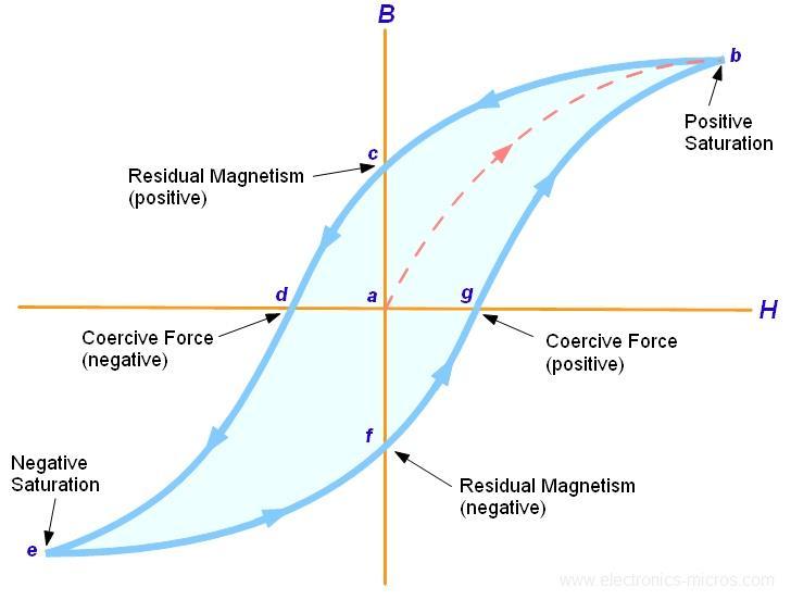
28 BH Curve Definition

29 Voltage Current B= V(t)dt H = ni l B-H Curve shows the hysteresis loop for the magnetic material in inductors and transformers Coil Characteristics Input: # of windings Cross sectional area Magnetic path length Cursor are used to measure magnetic field strength, H, and magnetic flux density, B H is calculated from the current, # windings and magnetic path length B is calculated as the integral of the voltage across the coil Parameter math is utilized for calculation of the magnetic permeability of the material B and H constants are individually entered and the resulting parameter is calculated as B/H

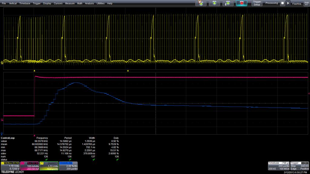
30 Control Loop Measurements AC In + + DC Out PWM Controller Isolated Feedback
31

32 Cycle 1 Period Cycle 2 Period Cycle 3 Period Cycle 4 Period Cycle 5 Period Cycle 6 Period Cycle 7 Period Cycle 8 Period Cycle 9 Period Voltage ns ns ns ns ns ns ns ns ns Time Period ns ns ns ns ns ns ns ns ns Time Parameter Track can be used to determine power supply modulation

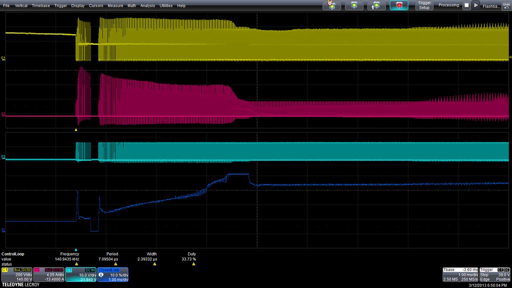
33 Pulse width begins to decrease Load disconnected Track function plots changing pulse width Settling time
34
35
36 Control Loop Measurements AC In + + DC Out PWM Controller Isolated Feedback
37 Power supply ripple measurement
38 Radiated Immunity Testing

39 Radiated Immunity Testing - Real Time Functional Performance Evaluation Deviation detection of a device under test (DUT) during exposure to a disturbance Functional state of the DUT is output through non-conductive fiber optic cables Mechanical mode tuner Devices under test are exposed to electric fields high enough to effect operation of nonshielded equipment. Transmit and receive antennas generate a controlled electric field RF-hardened fiber optic transmitters


40 Outside the reverberant chamber, oscilloscope masks test for acceptance criteria Optical receiver and O/E converter 16 channels performing mask test criteria such as signal high level, signal low level, frequency, duty cycle, and other criteria fit within tolerance limits described in the test plan


41 High Voltage Fiber Optically-isolated Probe? Amplifier/Modulating Transmitter A frequency modulating optical transmitter is used for signal and data transmission across a fiber optic cable. Attenuating Tip Accessories Available in a variety of voltage ranges, e.g., +/-1V, +/-5V, +/-20V and +/-40V with a simplified pin socket termination Fiber Optic Cable A standard 1m length cable is provided, but longer ones may be purchased for use. De-modulating Receiver The optical signal is received and de-modulated to an electrical output to the oscilloscope with correct voltage scaling.
42 High Voltage Active Single-ended (Fiber Optic) Probes Parameter Bandwidth Voltage Range (SE) Voltage Range (CM) Loading Attenuation CMRR Value 60 MHz 2 to 80V Virtually Unlimited 1-10MΩ 34-22pF Z IN =50kΩ@100 khz 2x to 80x >140 db A new topology specifically for measuring small signals floating on a HV DC bus
43 Power Integrity Example Jitter on a 10 MHz clock circuit is traced back to a 2.9 MHz Point-of-load (POL) DC-DC converter
 DC-DC converter Power delivery network Switched-mode AC-DC power")
44 Overview of DUT Power Delivery System for a Wireless Router Point-of-Load (POL) DC-DC converter Power delivery network Switched-mode AC-DC power supply


45 2.9 MHz POL DC-DC Converter Spectral Measurements The oscilloscope Spectrum Analyzer capability is used to detect frequency peaks of the POL Short 20 GS/s Long Acquisition 250 MS/s Spectrum Analyzer Table Peak Markers Correspond to Table
 TIE Jitter Overlay")

46 POL Ripple Contributes to Clock Jitter JitterKit can be used to quantify jitter on 10 MHz clock and trace it back to the POL 10 MHz clock acquisition (500 μs long) TIE Jitter Overlay of 10 MHz clock acquisition Histogram of TIE measurements TIE Jitter vs. time for the 10 MHz clock TIE Jitter Spectrum of 10 MHz Clock Spectrum Analysis Table from 2.9 MHz POL February 15,
47 Power Rail Probing
 (can be soldered-in and left in circuit) MCX PCB Mounts (4 GHz) (good for larger circuit boards")
 (attaches to compact U.FL PCB Mounts). U.FL PCB Mounts (compact size for dense, mobile or handheld systems)")
48 RP4030 Active Voltage/Power Rail Probe ProBuscompatible amplifier SMA to MCX short cable MCX Solder-in Lead (4 GHz) (can be soldered-in and left in circuit) MCX PCB Mounts (4 GHz) (good for larger circuit boards attach and leave in place for quick and easy connection to cable) MCX to SMA Adapter MCX to U.FL Lead (3 GHz) (attaches to compact U.FL PCB Mounts). U.FL PCB Mounts (compact size for dense, mobile or handheld systems)


49 Acquiring DC Power/Voltage Rails 5 mv/div 1.8 V offset 5 mv/div 1.8 V offset 1.8 V 0 V Coaxial Cable Input Terminated at 1 MΩ 1.8 V 0 V Passive Probe February 1, Power Rail Probe 1.8 V 0 V 5 mv/div 1.8 V offset Active Voltage Rail Probe
50 Motor Drive Analysis


51 Motor Drive Analysis Test Configuration Examples AC Induction Motor 2-wattmeter test configuration Brushless DC Motor test configuration

 Enable Zoom+Gate button and indicator (gray when ON )")
52 Mechanical Setup Torque Sensing Method Selection Select Units, Filter Cutoff, and Scaling Speed, Angle, Direction Method Selection Rotation direction is arbitrary select one of these to get correct sign of rotation parameter Waveform period synchronization setup (for per-cycle measurement analysis) Select the analog channel to use for Torque sensing input Speed & Angle setup changes depending on Method selected Angle is the arbitrary shaft rotation angle. Offset Angle allows correction to something not arbitrary (e.g. rotor field) Enable Zoom+Gate button and indicator (gray when ON )
53 Dynamic Motor Analysis


54 Dynamic Power Analysis - Zoom+Gate Operation Push Zoom+Gate button to create Zooms and Gate the Numerics table to zoomed area Zoomed Area in Acquisition Zooms Original, Full Record Length Acquisitions All table data is calculated on zoomed area only Displayed Sync Signal is Zoomed Per-cycle synthesized Waveforms are Zoomed Light Glows ON when in Zoom+Gate mode

55 Dynamic Drive Response Analysis

56 Efficiency Measurement on AC-AC 480V Motor Drive
 and C6 (current).")
57 Application example: Battery-powered brushless DC drill Waveforms captured from a battery-powered brushless DC drill. The Q-Scape tabs are labeled DC Bus, Drive Output, Mechanical, and Torque & Speed. 25 Mpt acquisitions are displayed on the left and zooms displayed on the right. The DC Bus signals are C3 (voltage) and C6 (current). The Drive Output signals are C1 and C2 (voltage) and C4 and C5 (current). The 2-wattmeter method is used to calculate three-phase Drive Output power. 12 bits and vertical zoom are used to show the DC bus and current signals. Torque is measured with C7 (from a dynamometer torque load cell) and Speed is measured with C8 (analog tachometer from a dynamometer). Hall sensors (Digital1) are also captured and could measure speed. Per-cycle synthesized waveforms showing Mechanical Power, Torque and Speed are plotted for the motor shaft output, and two XY plots are shown. The XY plots show Torque vs. Speed (top) of the full acquisition in pink (XY1: C7 vs. C8) and the zoomed area (XY2: Z7 vs. Z8) in light green. XY3 shows Z7 vs. Z8 but in a different scale. It is common to want to view Torque vs. Speed for a motor shaft output.
. 0 RPM is the vertical grid center.")
58 Robotics Application Using Resolver for Speed and Angle Sine and cosine signals from the resolver Plot of Speed and Angle calculated per-cycle by MDA 8 khz excitation frequency for the resolver. The Sync signal for the speed and angle measurements is this 8 khz excitation frequency. 300-pt Boxcar filter (300 points, ten 8 khz periods with 30 points/period). 0 RPM is the vertical grid center. As RPM goes positive, the motor shaft turns in one direction (Angle or F6 slope is positive), and as RPM goes negative, the motor shaft turns in the other direction (slope is negative). The Angle calculation resets to 0 degrees whenever a full shaft rotation occurs.
59 Motor test area (exterior view)
60 Motor test area (exterior / interior view)
61 Motor test area (interior view)
")
62 Motor test area (interior view)
63 Motor test area (interior view)

64 Motor drive analyzer testing 3 voltage phases and 3 current phases
65 Control room for motor test
66
67

68
Measurement and Analysis for Switchmode Power Design
 Measurement and Analysis for Switchmode Power Design Switched Mode Power Supply Measurements AC Input Power measurements Safe operating area Harmonics and compliance Efficiency Switching Transistor Losses
Today most of engineers use oscilloscope as the preferred measurement tool of choice when it comes to debugging and analyzing switching power
 Today most of engineers use oscilloscope as the preferred measurement tool of choice when it comes to debugging and analyzing switching power supplies. In this session we will learn about some basics of
LeCroy PowerMeasure System. Get the Complete Picture
 LeCroy PowerMeasure System Get the Complete Picture Power Measurements Made Easy! COMPLETE PACKAGE! POWER DEVICE ANALYSIS: measures power device saturation voltage, instantaneous power loss, safe operating
High Voltage Differential Probes HVD3605A, HVD3206A HVD310xA
 High Voltage Differential Probes HVD3605A, HVD3206A HVD310xA Key Features 1 kv, 2 kv, 6 kv CAT safety rated models Widest differential voltage ranges available Exceptional common-mode rejection ratio (CMRR)
How to Setup a Real-time Oscilloscope to Measure Jitter
 TECHNICAL NOTE How to Setup a Real-time Oscilloscope to Measure Jitter by Gary Giust, PhD NOTE-3, Version 1 (February 16, 2016) Table of Contents Table of Contents... 1 Introduction... 2 Step 1 - Initialize
Power Measurements for Switch-Mode Power Supplies SAVE Verona 2011
 Power Measurements for Switch-Mode Power Supplies SAVE Verona 2011 Agenda Power measurements tools Switch-mode power supplies Automated power measurements Summary Reference information 2 Switch-Mode Power
Measuring Power Supply Switching Loss with an Oscilloscope
 Measuring Power Supply Switching Loss with an Oscilloscope Our thanks to Tektronix for allowing us to reprint the following. Ideally, the switching device is either on or off like a light switch, and instantaneously
Instruction Manual Motor Drive Analyzer Software
 Instruction Manual Motor Drive Analyzer Software Motor Drive Analyzer Software Instruction Manual July 2018 Motor Drive Analyzer Software Instruction Manual 2018 Teledyne LeCroy, Inc. All rights reserved.
P a g e 1 ST985. TDR Cable Analyzer Instruction Manual. Analog Arts Inc.
 P a g e 1 ST985 TDR Cable Analyzer Instruction Manual Analog Arts Inc. www.analogarts.com P a g e 2 Contents Software Installation... 4 Specifications... 4 Handling Precautions... 4 Operation Instruction...
Probe Considerations for Low Voltage Measurements such as Ripple
 Probe Considerations for Low Voltage Measurements such as Ripple Our thanks to Tektronix for allowing us to reprint the following article. Figure 1. 2X Probe (CH1) and 10X Probe (CH2) Lowest System Vertical
High Voltage Differential Probes HVD3605, HVD3206 HVD310x
 High Voltage Differential Probes HVD3605, HVD3206 HVD310x Key Features 1 kv, 2 kv, 6 kv CAT safety rated models World s only 1500 Vdc safety rated probe per IEC/EN 61010-031:2015 Widest differential voltage
Saturation of Active Loop Antennas
 Saturation of Active Loop Antennas Alexander Kriz EMC and Optics Seibersdorf Laboratories 2444 Seibersdorf, Austria Abstract The EMC community is working towards shorter test distances for radiated emission
Guide Version Five techniques for fast, accurate power integrity measurements
 Guide Version 01.00 Five techniques for fast, accurate power integrity measurements Rail voltages are getting smaller, and tolerances are decreasing. As a result, making accurate power rail measurements
PowerAmp Design. PowerAmp Design PAD112 HIGH VOLTAGE OPERATIONAL AMPLIFIER
 PowerAmp Design Rev C KEY FEATURES LOW COST HIGH VOLTAGE 150 VOLTS HIGH OUTPUT CURRENT 5 AMPS 50 WATT DISSIPATION CAPABILITY 100 WATT OUTPUT CAPABILITY INTEGRATED HEAT SINK AND FAN COMPATIBLE WITH PAD123
Techniques to reduce electromagnetic noise produced by wired electronic devices
 Rok / Year: Svazek / Volume: Číslo / Number: Jazyk / Language 2016 18 5 EN Techniques to reduce electromagnetic noise produced by wired electronic devices - Tomáš Chvátal xchvat02@stud.feec.vutbr.cz Faculty
University of North Carolina-Charlotte Department of Electrical and Computer Engineering ECGR 3157 Electrical Engineering Design II Fall 2013
 Exercise 1: PWM Modulator University of North Carolina-Charlotte Department of Electrical and Computer Engineering ECGR 3157 Electrical Engineering Design II Fall 2013 Lab 3: Power-System Components and
IsoVu Optically Isolated DC - 1 GHz Measurement System Offers >120 db CMRR with 2kV Common Mode Range
 IsoVu Optically Isolated DC - 1 GHz Measurement System Offers >120 db CMRR with 2kV Common Mode Range Introduction This white paper describes the optically isolated measurement system architecture trademarked
EMC / ESD Pulse Measurements Using Oscilloscopes September /16/$ IEEE
 EMC / ESD Pulse Measurements Using Oscilloscopes September 2016 978-1-5090-1416-3/16/$31.00 2016 IEEE Contents EMC Measurement Categories and Requirements ESD Pulse Test Requirements and Measurement Thresholds
PowerAmp Design. PowerAmp Design PAD20 COMPACT HIGH VOLTAGE OP AMP
 PowerAmp Design Rev C KEY FEATURES LOW COST HIGH VOLTAGE 150 VOLTS HIGH OUTPUT CURRENT 5A 40 WATT DISSIPATION CAPABILITY 80 WATT OUTPUT CAPABILITY INTEGRATED HEAT SINK AND FAN SMALL SIZE 40mm SQUARE RoHS
Experiment 1: Instrument Familiarization (8/28/06)
") Electrical Measurement Issues Experiment 1: Instrument Familiarization (8/28/06) Electrical measurements are only as meaningful as the quality of the measurement techniques and the instrumentation applied
Electrical Measurement Issues Experiment 1: Instrument Familiarization (8/28/06) Electrical measurements are only as meaningful as the quality of the measurement techniques and the instrumentation applied
Contents. ZT530PCI & PXI Specifications. Arbitrary Waveform Generator. 16-bit, 400 MS/s, 2 Ch
 ZT530PCI & PXI Specifications Arbitrary Waveform Generator 16-bit, 400 MS/s, 2 Ch Contents Outputs... 2 Digital-to-Analog Converter (DAC)... 3 Internal DAC Clock... 3 Spectral Purity... 3 External DAC
 1 of 6 03/12/2012 14:56 2012-12-03 HAMEG > Products > Accessories > Probes http://www.hameg.com/186.0.html P R O B E S H Z 5 6-2 * AC/ DC Current Clamps This AC/DC Current Probe is used to measure currents
Memo. 1 Summary. 1.1 Introduction. 1.2 Experiments. 1.3 Conclusion
 Topic: Tested: Date: Author: High frequency oscillations measured with high bandwidth current sensors at low current Pearson 2878 and SDN-414 shunts with different resistance values 2014 April 11 th Martin
EMC Pulse Measurements
 EMC Pulse Measurements and Custom Thresholding Presented to the Long Island/NY IEEE Electromagnetic Compatibility and Instrumentation & Measurement Societies - May 13, 2008 Surge ESD EFT Contents EMC measurement
Getting the most out of your Measurements Workshop. Mike Schnecker
 Getting the most out of your Measurements Workshop Mike Schnecker Agenda Oscilloscope Basics Using a RTE1000 Series Oscilloscope. Probing Basics Passive probe compensation Ground lead effects Vertical
MSK4310 Demonstration
 MSK4310 Demonstration The MSK4310 3 Phase DC Brushless Speed Controller hybrid is a complete closed loop velocity mode controller for driving a brushless motor. It requires no external velocity feedback
ECE3204 D2015 Lab 1. See suggested breadboard configuration on following page!
 ECE3204 D2015 Lab 1 The Operational Amplifier: Inverting and Non-inverting Gain Configurations Gain-Bandwidth Product Relationship Frequency Response Limitation Transfer Function Measurement DC Errors
Models 296 and 295 combine sophisticated
 Established 1981 Advanced Test Equipment Rentals www.atecorp.com 800-404-ATEC (2832) Models 296 and 295 50 MS/s Synthesized Multichannel Arbitrary Waveform Generators Up to 4 Independent Channels 10 Standard
The Discussion of this exercise covers the following points:
 Exercise 3-2 Frequency-Modulated CW Radar EXERCISE OBJECTIVE When you have completed this exercise, you will be familiar with FM ranging using frequency-modulated continuous-wave (FM-CW) radar. DISCUSSION
Sophisticated Power Loss Analysis Using A Digital Phosphor Oscilloscope
 Sophisticated Power Loss Analysis Using A Digital Phosphor Oscilloscope Quickly Locate Power Dissipation in Switching Power Supplies With demand for power driving architectural changes to switching power
A Practical Primer On Motor Drives (Part 13): Motor Drive Control Architectures And Algorithms
: Motor Drive Control Architectures And Algorithms") ISSUE: February 2017 A Practical Primer On Motor Drives (Part 13): Motor Drive Control Architectures And Algorithms by Ken Johnson, Teledyne LeCroy, Chestnut Ridge, N.Y. Part 12 began the explanation of
ISSUE: February 2017 A Practical Primer On Motor Drives (Part 13): Motor Drive Control Architectures And Algorithms by Ken Johnson, Teledyne LeCroy, Chestnut Ridge, N.Y. Part 12 began the explanation of
Experiment 1: Instrument Familiarization
 Electrical Measurement Issues Experiment 1: Instrument Familiarization Electrical measurements are only as meaningful as the quality of the measurement techniques and the instrumentation applied to the
Feedback Devices. By John Mazurkiewicz. Baldor Electric
 Feedback Devices By John Mazurkiewicz Baldor Electric Closed loop systems use feedback signals for stabilization, speed and position information. There are a variety of devices to provide this data, such
U1571A Ni-MH Battery Pack for U1600A Handheld Oscilloscopes
 United States Home >... > Oscilloscope Accessories > U1600 Series Oscilloscope Accessories > U1571A Ni-MH Battery Pack for U1600A Handheld Oscilloscopes Key Specifications Features Ni-MH Battery Pack,
PXIe Contents. Required Software CALIBRATION PROCEDURE
 CALIBRATION PROCEDURE PXIe-5160 This document contains the verification and adjustment procedures for the PXIe-5160. Refer to ni.com/calibration for more information about calibration solutions. Contents
ArbStudio Arbitrary Waveform Generators
 ArbStudio Arbitrary Waveform Generators Key Features Outstanding performance with 16-bit, 1 GS/s sample rate and 2 Mpts/Ch 2 and 4 channel models Digital pattern generator PWM mode Sweep and burst modes
Optimizing Performance Using Slotless Motors. Mark Holcomb, Celera Motion
 Optimizing Performance Using Slotless Motors Mark Holcomb, Celera Motion Agenda 1. How PWM drives interact with motor resistance and inductance 2. Ways to reduce motor heating 3. Locked rotor test vs.
High Speed Digital Design & Verification Seminar. Measurement fundamentals
 High Speed Digital Design & Verification Seminar Measurement fundamentals Agenda Sources of Jitter, how to measure and why Importance of Noise Select the right probes! Capture the eye diagram Why measure
Multiple Instrument Station Module
 Multiple Instrument Station Module Digital Storage Oscilloscope Vertical Channels Sampling rate Bandwidth Coupling Input impedance Vertical sensitivity Vertical resolution Max. input voltage Horizontal
Analog Arts SF990 SF880 SF830 Product Specifications
 1 www.analogarts.com Analog Arts SF990 SF880 SF830 Product Specifications Analog Arts reserves the right to change, modify, add or delete portions of any one of its specifications at any time, without
Combinational logic: Breadboard adders
 ! ENEE 245: Digital Circuits & Systems Lab Lab 1 Combinational logic: Breadboard adders ENEE 245: Digital Circuits and Systems Laboratory Lab 1 Objectives The objectives of this laboratory are the following:
WaveAce 1000 and 2000 Oscilloscopes
 1000 and 2000 Oscilloscopes 40 MHz 300 MHz Key Features Sample rates up to 2 GS/s 1 Mpts/ch memory, 2 Mpts interleaved 7" color display on all models 32 automatic measurements Multi-language user interface
Basic Communication Laboratory Manual. Shimshon Levy&Harael Mualem
 Basic Communication Laboratory Manual Shimshon Levy&Harael Mualem September 2006 CONTENTS 1 The oscilloscope 2 1.1 Objectives... 2 1.2 Prelab... 2 1.3 Background Theory- Analog Oscilloscope...... 3 1.4
Analog Arts SL987 SL957 SL937 SL917 Product Specifications [1]
![Analog Arts SL987 SL957 SL937 SL917 Product Specifications [1]](/thumbs/95/126095980.jpg "Analog Arts SL987 SL957 SL937 SL917 Product Specifications [1]") www.analogarts.com Analog Arts SL987 SL957 SL937 SL917 Product Specifications [1] 1. These models include: an oscilloscope, a spectrum analyzer, a data recorder, a frequency & phase meter, an arbitrary
www.analogarts.com Analog Arts SL987 SL957 SL937 SL917 Product Specifications [1] 1. These models include: an oscilloscope, a spectrum analyzer, a data recorder, a frequency & phase meter, an arbitrary
PowerAmp Design. PowerAmp Design PAD117A RAIL TO RAIL OPERATIONAL AMPLIFIER
 PowerAmp Design RAIL TO RAIL OPERATIONAL AMPLIFIER Rev J KEY FEATURES LOW COST RAIL TO RAIL INPUT & OUTPUT SINGLE SUPPLY OPERATION HIGH VOLTAGE 100 VOLTS HIGH OUTPUT CURRENT 15A 250 WATT OUTPUT CAPABILITY
Notes on OR Data Math Function
 A Notes on OR Data Math Function The ORDATA math function can accept as input either unequalized or already equalized data, and produce: RF (input): just a copy of the input waveform. Equalized: If the
TAKE THE MYSTERY OUT OF PROBING. 7 Common Oscilloscope Probing Pitfalls to Avoid
 TAKE THE MYSTERY OUT OF PROBING 7 Common Oscilloscope Probing Pitfalls to Avoid Introduction Understanding common probing pitfalls and how to avoid them is crucial in making better measurements. In an
AWG-GS bit 2.5GS/s Arbitrary Waveform Generator
 KEY FEATURES 2.5 GS/s Real Time Sample Rate 14-bit resolution 2 Channels Long Memory: 64 MS/Channel Direct DAC Out - DC Coupled: 1.6 Vpp Differential / 0.8 Vpp > 1GHz Bandwidth RF Amp Out AC coupled -10
Transformer Waveforms
 OBJECTIVE EXPERIMENT Transformer Waveforms Steady-State Testing and Performance of Single-Phase Transformers Waveforms The voltage regulation and efficiency of a distribution system are affected by the
CONNECTING THE PROBE TO THE TEST INSTRUMENT
 2SHUDWLRQ 2SHUDWLRQ Caution The input circuits in the AP034 Active Differential Probe incorporate components that protect the probe from damage resulting from electrostatic discharge (ESD). Keep in mind
University of New Hampshire InterOperability Laboratory Gigabit Ethernet Consortium
 University of New Hampshire InterOperability Laboratory Gigabit Ethernet Consortium As of June 18 th, 2003 the Gigabit Ethernet Consortium Clause 40 Physical Medium Attachment Conformance Test Suite Version
U1604A Handheld Oscilloscopes, 40 MHz
 Products & Services Technical Support Buy Industries About Agilent Search: All Test & Measurement Go United States Home >... > Oscilloscopes > U1600A Series handheld oscilloscopes (2 models) > U1604A Handheld
Vishay Siliconix AN724 Designing A High-Frequency, Self-Resonant Reset Forward DC/DC For Telecom Using Si9118/9 PWM/PSM Controller.
 AN724 Designing A High-Frequency, Self-Resonant Reset Forward DC/DC For Telecom Using Si9118/9 PWM/PSM Controller by Thong Huynh FEATURES Fixed Telecom Input Voltage Range: 30 V to 80 V 5-V Output Voltage,
CX1100 Series Current and Differential Sensors
 DATA SHEET CX00 Series Current and Differential Sensors CX0A Current Sensor, Single Channel CX0A Current Sensor, Dual Channel CX03A Current Sensor, Low Side CX04A Current Sensor, Selectable Resistive Sensor
Arbitrary/Function Generator AFG1000 Series Datasheet
 Arbitrary/Function Generator AFG1000 Series Datasheet 99 Washington Street Melrose, MA 02176 Phone 781-665-1400 Toll Free 1-800-517-8431 Visit us at www.testequipmentdepot.com Compatible with TekSmartLab
Practical Measurements considerations for GaN and SiC technologies ANDREA VINCI EMEA MARKET DEVELOPMENT MANAGER POWER ELECTRONICS
 Practical Measurements considerations for GaN and SiC technologies ANDREA VINCI EMEA MARKET DEVELOPMENT MANAGER POWER ELECTRONICS PLEASED TO MEET YOU 2 Evolving Test Solutions with Semiconductors WAFER
Moku:Lab. Specifications INSTRUMENTS. Moku:Lab, rev
 Moku:Lab L I Q U I D INSTRUMENTS Specifications Moku:Lab, rev. 2018.1 Table of Contents Hardware 4 Specifications 4 Analog I/O 4 External trigger input 4 Clock reference 5 General characteristics 5 General
ArbStudio Arbitrary Waveform Generators. Powerful, Versatile Waveform Creation
 ArbStudio Arbitrary Waveform Generators Powerful, Versatile Waveform Creation UNMATCHED WAVEFORM UNMATCHED WAVEFORM GENERATION GENERATION Key Features 125 MHz bandwidth 1 GS/s maximum sample rate Long
PX8000 Precision Power Scope with Features of High-accuracy Power Meter and Waveform Measuring Instrument
 PX8000 Precision Power Scope with Features of High-accuracy Power Meter and Waveform Measuring Instrument Osamu Itou *1 Satoru Suzuki *1 Hiroshi Yagyuu *2 Kazuo Kawasumi *1 Yokogawa developed the PX8000
200 ma Output Current High-Speed Amplifier AD8010
 a FEATURES 2 ma of Output Current 9 Load SFDR 54 dbc @ MHz Differential Gain Error.4%, f = 4.43 MHz Differential Phase Error.6, f = 4.43 MHz Maintains Video Specifications Driving Eight Parallel 75 Loads.2%
Electrical Motor Power Measurement & Analysis
 Electrical Motor Power Measurement & Analysis Understand the basics to drive greater efficiency Test&Measurement Energy is one of the highest cost items in a plant or facility, and motors often consume
Introduction to Oscilloscopes Instructor s Guide
 Introduction to Oscilloscopes A collection of lab exercises to introduce you to the basic controls of a digital oscilloscope in order to make common electronic measurements. Revision 1.0 Page 1 of 25 Copyright
Output Impedance. Duty Cycle Range. Buffer Size Resolution. PROTECTION Input Over Voltage. Output Short Circuit. TRIGGERING Sources.
 3 Channel Digital Storage Oscilloscope (DSO) Instrument VERTICAL SPECIFICATIONS Analogue Bandwidth (-3dB) Bandwidth Limiting Rise time (10% to 90%, calculated) Input ranges (full scale) Input sensitivity
LAB I. INTRODUCTION TO LAB EQUIPMENT
 1. OBJECTIVE LAB I. INTRODUCTION TO LAB EQUIPMENT In this lab you will learn how to properly operate the oscilloscope Agilent MSO6032A, the Keithley Source Measure Unit (SMU) 2430, the function generator
Power Measurements and Analysis: Challenges and Solutions
 Power Measurements and Analysis: Challenges and Solutions Selu Gupta HW Design Engineer Tektronix, Inc. Beaverton, Oregon USA ABSTRACT: The job of a switch mode power supply and power electronics engineer
Test Plan for Hearing Aid Compatibility
 Test Plan for Hearing Aid Compatibility Version Number 3.1 February 2017 2017 CTIA - The Wireless Association. All rights reserved. CTIA hereby grants to CTIA Authorized Testing Laboratories (CATLs), and
Transient Data Acquisition System, TAS 4-40 Potential-free measurement of fast rise pulses:
 Transient Data Acquisition System, TAS 4-40 Potential-free measurement of fast rise pulses: High precision measurement of fast rising voltages and currents causes considerable problems in many spheres
Arbitrary/Function Waveform Generators 4075B Series
 Data Sheet Arbitrary/Function Waveform Generators Point-by-Point Signal Integrity The Arbitrary/Function Waveform Generators are versatile high-performance single- and dual-channel arbitrary waveform generators
ELEC 0017: ELECTROMAGNETIC COMPATIBILITY LABORATORY SESSIONS
 Academic Year 2015-2016 ELEC 0017: ELECTROMAGNETIC COMPATIBILITY LABORATORY SESSIONS V. BEAUVOIS P. BEERTEN C. GEUZAINE 1 CONTENTS: EMC laboratory session 1: EMC tests of a commercial Christmas LED light
MAKING TRANSIENT ANTENNA MEASUREMENTS
 MAKING TRANSIENT ANTENNA MEASUREMENTS Roger Dygert, Steven R. Nichols MI Technologies, 1125 Satellite Boulevard, Suite 100 Suwanee, GA 30024-4629 ABSTRACT In addition to steady state performance, antennas
Exercise 6. Range and Angle Tracking Performance (Radar-Dependent Errors) EXERCISE OBJECTIVE
 EXERCISE OBJECTIVE") Exercise 6 Range and Angle Tracking Performance EXERCISE OBJECTIVE When you have completed this exercise, you will be familiar with the radardependent sources of error which limit range and angle tracking
Exercise 6 Range and Angle Tracking Performance EXERCISE OBJECTIVE When you have completed this exercise, you will be familiar with the radardependent sources of error which limit range and angle tracking
Fluke 192/196/199. ScopeMeter. Users Manual
 Fluke 192/196/199 ScopeMeter Users Manual 4822 872 00983 October 2000, Rev.2, 2/01 2000 Fluke Corporation. All rights reserved. Printed in the Netherlands. All product names are trademarks of their respective
The DC Machine Laboration 3
 EIEN25 - Power Electronics: Devices, Converters, Control and Applications The DC Machine Laboration 3 Updated February 19, 2018 1. Before the lab, look through the manual and make sure you are familiar
Practical Considerations in Measuring Power and Efficiency on PWM and Distorted Waveforms during Dynamic Operating Conditions
 Practical Considerations in Measuring Power and Efficiency on PWM and Distorted Waveforms during Dynamic Operating Conditions APEC 2016 Industry Session Author: Ken Johnson, Director of Marketing, Product
Agilent AN 1275 Automatic Frequency Settling Time Measurement Speeds Time-to-Market for RF Designs
 Agilent AN 1275 Automatic Frequency Settling Time Measurement Speeds Time-to-Market for RF Designs Application Note Fast, accurate synthesizer switching and settling are key performance requirements in
Single Supply, Rail to Rail Low Power FET-Input Op Amp AD820
 a FEATURES True Single Supply Operation Output Swings Rail-to-Rail Input Voltage Range Extends Below Ground Single Supply Capability from + V to + V Dual Supply Capability from. V to 8 V Excellent Load
U1881A and U1882A Power Measurement Application for InfiniiVision and Infiniium Oscilloscopes
 U1881A and U1882A Power Measurement Application for InfiniiVision and Infiniium Oscilloscopes Data Sheet Fast, automatic and reliable characterization of switching mode power devices Today s power supply
Transient Current Measurement for Advance Materials & Devices
 & Devices 8 May 2017 Brian YEO Application Engineer Keysight Technologies Agenda 2 High speed data acquisition basics Challenges & solutions for transient current measurement. Considerations when making
Analog Arts SF900 SF650 SF610 Product Specifications
 www.analogarts.com Analog Arts SF900 SF650 SF610 Product Specifications Analog Arts reserves the right to change, modify, add or delete portions of any one of its specifications at any time, without prior
Analog Arts SG985 SG884 SG834 SG814 Product Specifications [1]
![Analog Arts SG985 SG884 SG834 SG814 Product Specifications [1]](/thumbs/94/122371203.jpg "Analog Arts SG985 SG884 SG834 SG814 Product Specifications [1]") www.analogarts.com Analog Arts SG985 SG884 SG834 SG814 Product Specifications [1] 1. These models include: an oscilloscope, a spectrum analyzer, a data recorder, a frequency & phase meter, and an arbitrary
www.analogarts.com Analog Arts SG985 SG884 SG834 SG814 Product Specifications [1] 1. These models include: an oscilloscope, a spectrum analyzer, a data recorder, a frequency & phase meter, and an arbitrary
Measuring Power Supply Switching Loss with an Oscilloscope
 Measuring Power Supply Switching Loss with an Oscilloscope Application Note Introduction With the demand for improving power efficiency and extending the operating time of battery-powered devices, the
Switch Mode Power Supply Measurements
 Switch Mode Power Supply Measurements Application Note Using an Agilent InfiniiVision 3000/4000 X-Series Oscilloscope With the Power Measurements Option Introduction Agilent s 3000 and 4000 X-Series oscilloscopes
ME 365 EXPERIMENT 1 FAMILIARIZATION WITH COMMONLY USED INSTRUMENTATION
 Objectives: ME 365 EXPERIMENT 1 FAMILIARIZATION WITH COMMONLY USED INSTRUMENTATION The primary goal of this laboratory is to study the operation and limitations of several commonly used pieces of instrumentation:
CHAPTER 6. Motor Driver
 CHAPTER 6 Motor Driver In this lab, we will construct the circuitry that your robot uses to drive its motors. However, before testing the motor circuit we will begin by making sure that you are able to
Fluke MDA-510 and MDA-550 Motor Drive Analyzer
 TECHNICAL DATA Fluke MDA-510 and MDA-550 Motor Drive Analyzer Simplify complex motor-drive troubleshooting with guided test setups and automated drive measurements that provide reliable, repeatable test
KM4110/KM mA, Low Cost, +2.7V & +5V, 75MHz Rail-to-Rail Amplifiers
 + + www.fairchildsemi.com KM411/KM41.5mA, Low Cost, +.7V & +5V, 75MHz Rail-to-Rail Amplifiers Features 55µA supply current 75MHz bandwidth Power down to I s = 33µA (KM41) Fully specified at +.7V and +5V
IT.MLD900 SENSORS AND TRANSDUCERS TRAINER. Signal Conditioning
 SENSORS AND TRANSDUCERS TRAINER IT.MLD900 The s and Instrumentation Trainer introduces students to input sensors, output actuators, signal conditioning circuits, and display devices through a wide range
2 Operation. Operation. Getting Started
 2 Operation Operation Getting Started Access the Ethernet Package by pressing the ANALYSIS PACKAGES button (MATH on LC scopes). A menu showing all the packages installed on the DSO is displayed. Select
Rohde & Schwarz EMI/EMC debugging with modern oscilloscope. Ing. Leonardo Nanetti Rohde&Schwarz
 Rohde & Schwarz EMI/EMC debugging with modern oscilloscope Ing. Leonardo Nanetti Rohde&Schwarz EMI debugging Agenda l The basics l l l l The idea of EMI debugging How is it done? Application example What
PDN Probes. P2100A/P2101A Data Sheet. 1-Port and 2-Port 50 ohm Passive Probes
 P2100A/P2101A Data Sheet PDN Probes 1-Port and 2-Port 50 ohm Passive Probes power integrity PDN impedance testing ripple PCB resonances transient step load stability and NISM noise TDT/TDR clock jitter
Exercise 1-4. The Radar Equation EXERCISE OBJECTIVE DISCUSSION OUTLINE DISCUSSION OF FUNDAMENTALS
 Exercise 1-4 The Radar Equation EXERCISE OBJECTIVE When you have completed this exercise, you will be familiar with the different parameters in the radar equation, and with the interaction between these
Probes and Accessories
 99 Washington Street Melrose, MA 02176 Phone 781-665-1400 Toll Free 1-800-517-8431 Visit us at www.testequipmentdepot.com Probes and Accessories Your Guide to Selecting the Right Probe Measurement Accuracy
User s Manual for Integrator Short Pulse ISP16 10JUN2016
 User s Manual for Integrator Short Pulse ISP16 10JUN2016 Specifications Exceeding any of the Maximum Ratings and/or failing to follow any of the Warnings and/or Operating Instructions may result in damage
Lab 4. Crystal Oscillator
 Lab 4. Crystal Oscillator Modeling the Piezo Electric Quartz Crystal Most oscillators employed for RF and microwave applications use a resonator to set the frequency of oscillation. It is desirable to
Isolated, Frequency Input 5B45 / 5B46 FEATURES APPLICATIONS PRODUCT OVERVIEW FUNCTIONAL BLOCK DIAGRAM
 Isolated, Frequency Input 5B45 / 5B46 FEATURES Isolated Frequency Input. Amplifies, Protects, Filters, and Isolates Analog Input. Generates an output of 0 to +5V proportional to input frequency. Model
Product Catalog. For more information, please contact:
 Product Catalog For more information, please contact: HDO4000 OSCILLOSCOPES Debug in High Definition 200 MHz 1 GHz Combining Teledyne LeCroy s HD4096 high definition technology, with long memory, a compact
DPO3PWR, MDO3PWR and DPO4PWR Power Analysis Modules ZZZ User Manual
 x DPO3PWR, MDO3PWR and DPO4PWR Power Analysis Modules ZZZ User Manual *P071263101* 071-2631-01 xx DPO3PWR, MDO3PWR and DPO4PWR Power Analysis Modules ZZZ User Manual www.tektronix.com 071-2631-01 Copyright
ELC224 Final Review (12/10/2009) Name:
 Name:") ELC224 Final Review (12/10/2009) Name: Select the correct answer to the problems 1 through 20. 1. A common-emitter amplifier that uses direct coupling is an example of a dc amplifier. 2. The frequency
ELC224 Final Review (12/10/2009) Name: Select the correct answer to the problems 1 through 20. 1. A common-emitter amplifier that uses direct coupling is an example of a dc amplifier. 2. The frequency
Debugging EMI Using a Digital Oscilloscope. Dave Rishavy Product Manager - Oscilloscopes
 Debugging EMI Using a Digital Oscilloscope Dave Rishavy Product Manager - Oscilloscopes 06/2009 Nov 2010 Fundamentals Scope Seminar of DSOs Signal Fidelity 1 1 1 Debugging EMI Using a Digital Oscilloscope
AP034-OM-E Rev D ISSUED: January 2000 ²
 3HUIRUPDQFH9HULILFDWLRQ 3HUIRUPDQFH9HULILFDWLRQ This procedure can be used to verify the warranted characteristics of the AP034 Active Differential Probe. The recommended calibration interval for the model