Fields and Waves I. Lecture 26. Intro to Antennas & Propagation K. A. Connor
|
|
|
- Sydney Haynes
- 6 years ago
- Views:
Transcription
1 Fields and Waves I Lecture 26 Intro to Antennas & Propagation K. A. Connor Electrical, Computer, and Systems Engineering Department Rensselaer Polytechnic Institute, Troy, NY
2 These Slides Were Prepared by Prof. Kenneth A. Connor Using Original Materials Written Mostly by the Following: Kenneth A. Connor ECSE Department, Rensselaer Polytechnic Institute, Troy, NY J. Darryl Michael GE Global Research Center, Niskayuna, NY Thomas P. Crowley National Institute of Standards and Technology, Boulder, CO Sheppard J. Salon ECSE Department, Rensselaer Polytechnic Institute, Troy, NY Lale Ergene ITU Informatics Institute, Istanbul, Turkey Jeffrey Braunstein Chung-Ang University, Seoul, Korea Materials from other sources are referenced where they are used. Those listed as Ulaby are figures from Ulaby s textbook. 9 February 2007 Fields and Waves I 2


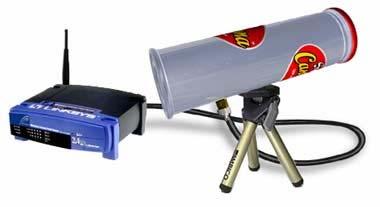
3 Examples of Antennas 9 February 2007 Fields and Waves I 3

4 Antennas 9 February 2007 Fields and Waves I 4

5 moteiv Tmote Sky Inverted F Antenna 9 February 2007 Fields and Waves I 5

6 moteiv Tmote Sky 9 February 2007 Fields and Waves I 6
7 moteiv Tmote Sky 9 February 2007 Fields and Waves I 7
8 moteiv Tmote Sky 9 February 2007 Fields and Waves I 8
9 moteiv Tmote Sky 9 February 2007 Fields and Waves I 9
10 9 February 2007 Fields and Waves I 10
11 Transmission Lines & Antennas Review Transmission Lines Review Boundary Conditions Review Voltage, Current, Electric and Magnetic Fields Etc. 9 February 2007 Fields and Waves I 11
= z E e + E e x + + jβz H y ()= z Ee + jβz η Ee + jβz 9 February 2007 Fields and Waves I")
12 TEM Waves on Transmission Lines Connecting Uniform Plane Waves with Voltages and Currents on Transmission Lines: jβz E ()= z E e + E e x + + jβz H y ()= z Ee + jβz η Ee + jβz 9 February 2007 Fields and Waves I 12
13 TEM Waves These fields can exist in the region between the conducting plates if the boundary conditions on the plates are reasonably satisfied. Since the electric field has only an x component, it is totally normal to the conducting boundaries. This can occur if there is a surface charge on the boundary, ρ = εe () z = εe e jβz + εe e + jβz s x + The magnetic field is totally tangent to the conducting boundary, which can occur if there is a surface current density given by J = H () z = s y Ee + jβz η Ee + jβz 9 February 2007 Fields and Waves I 13
14 TEM Waves Then, assuming that the lower plate is grounded, the voltage on the upper plate will be () s x vz = E() zdx= see + see = Ve + Ve jβz jβz jβz + jβz + where we have integrated the electric field along the vertical (red) w path shown. s 9 February 2007 Fields and Waves I 14
15 TEM Waves To connect the magnetic field with the current, we must integrate along a closed path that encloses one of the two conductors. The bottom path shown includes the horizontal (green) path inside the field region and the blue path outside of the field region. (We assume no fringing in this ideal case.) The magnetic field only contributes along the green path. Thus () w iz = H() zdy= 0 y we e + jβz we e η + jβz = wse e + wse e = Ve ηs w jβz + jβz jβz + jβz + ηs Ve 9 February 2007 Fields and Waves I 15
16 TEM Waves For a parallel plate waveguide (stripline), the inductance and capacitance per unit length and intrinsic impedance are c w = ε s l s = μ w μs l Z = w s c = s o w = μ w = η ε ε w s 9 February 2007 Fields and Waves I 16
17 TEM Waves so the current expression is iz ()= Ve + jβz Ve Z o + jβz We could have determined this current from the surface current density so we should check to be sure that the two results agree. The total current at any z should be given by iz Jw Ee Ee + + ()= s = w η as before. Ve + Ve Z jβz jβz jβz + jβz = o 9 February 2007 Fields and Waves I 17
18 TEM Waves Finally, we can check to see if the charge per unit length (as determined from the boundary condition) gives us the usual capacitance per unit length. jβz + jβz εw jβz jβz q = ρsw = εwe+ e + εwe e = + = s as expected. ( + Ve Ve ) + cvz () The same analysis can be done for coaxial cables and two-wire lines. The general results are the same. 9 February 2007 Fields and Waves I 18
19 Standing Waves: Voltage Standing Wave with Short Circuit Load Constructive Interference Destructive Interference 9 February 2007 Fields and Waves I 19
20 Standing Waves: Voltage Standing Wave with Open Circuit Load 9 February 2007 Fields and Waves I 20
21 Java Applet of Waves Standing Wave 9 February 2007 Fields and Waves I 21
22 Simple Antennas Currents on Wire Antennas General Types of Antennas The Hertzian Dipole as the Model Antenna Other Simple Wire Configurations Antenna Parameters & Analysis Radiation Patterns Yagi & Patch Antennas Polarization 9 February 2007 Fields and Waves I 22


23 Simple Wire Antenna Currents From CTA Johnk Engineering Electromagnetic Fields & Waves 9 February 2007 Fields and Waves I 23
24 Simple Wire Antenna Currents 9 February 2007 Fields and Waves I 24
25 Simple Wire Antenna Currents 9 February 2007 Fields and Waves I 25
26 Simple Wire Antenna Currents 9 February 2007 Fields and Waves I 26
27 Simple Wire Antenna Currents 9 February 2007 Fields and Waves I 27
28 Types of Antennas 9 February 2007 Fields and Waves I 28
29 Hertzian Dipole Constant Currents Note the Coordinates 9 February 2007 Fields and Waves I 29
30 Hertzian Dipole 9 February 2007 Fields and Waves I 30
31 Note that the waves become planar at large distances 9 February 2007 Fields and Waves I 31
32 Hertzian Dipole Radiation is primarily to the side Radiation is isotropic or uniform around the axis of the antenna Little or no radiation up or down 9 February 2007 Fields and Waves I 32
33 9 February 2007 Fields and Waves I 33
34 9 February 2007 Fields and Waves I 34
35 Short Dipole 9 February 2007 Fields and Waves I 35
36 9 February 2007 Fields and Waves I 36

37 Aperture Antennas 9 February 2007 Fields and Waves I 37
38 Antenna Parameters Calculate the Electric and Magnetic Fields from the Antenna Currents usually requires the use of potentials Far Fields are Products of terms like the following (depends on current and inversely on position), spherical wave, field pattern F( θ) Determine the Poynting Vector Power Density is product of E and H average goes inversely with position squared and with F 2 ( θ) Gain is the ratio of power density to isotropic value Radiation Resistance is twice the average total power divided by the current squared 9 February 2007 Fields and Waves I 38
39 Antenna Analysis Hertzian Dipole 9 February 2007 Fields and Waves I 39
40 Antenna Analysis 9 February 2007 Fields and Waves I 40
41 Antenna Analysis 9 February 2007 Fields and Waves I 41
42 Antenna Analysis Keep Only The Largest Terms in the Far Field 9 February 2007 Fields and Waves I 42
43 Antenna Analysis F 2 ( θ) 9 February 2007 Fields and Waves I 43
44 Antenna Analysis 9 February 2007 Fields and Waves I 44
45 Note that the waves become planar at large distances 9 February 2007 Fields and Waves I 45
46 Hertzian Dipole Radiation is primarily to the side Radiation is isotropic or uniform around the axis of the antenna Little or no radiation up or down 9 February 2007 Fields and Waves I 46
47 Half Wave Dipole F 2 ( θ) 9 February 2007 Fields and Waves I 47

48 Radiation Patterns 9 February 2007 Fields and Waves I 48

49 9 February 2007 Fields and Waves I 49

50 9 February 2007 Fields and Waves I 50
51 9 February 2007 Fields and Waves I 51

52 9 February 2007 Fields and Waves I 52

53 9 February 2007 Fields and Waves I 53
54 9 February 2007 Fields and Waves I 54


55 Antenna Patterns 9 February 2007 Fields and Waves I 55


56 Yagi Antenna 5.8GHz 9 February 2007 Fields and Waves I 56
57 10 Element Yagi 9 February 2007 Fields and Waves I 57

58 9 February 2007 Fields and Waves I 58

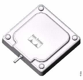
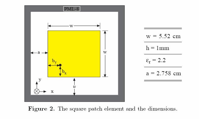
59 Patch Antenna 9 February 2007 Fields and Waves I 59
60 Patch Antenna 9 February 2007 Fields and Waves I 60
61 Patch Antenna 9 February 2007 Fields and Waves I 61

62 Patch Antenna 9 February 2007 Fields and Waves I 62
63 9 February 2007 Fields and Waves I 63

64 9 February 2007 Fields and Waves I 64
65 9 February 2007 Fields and Waves I 65
66 9 February 2007 Fields and Waves I 66


67 9 February 2007 Fields and Waves I 67
68 9 February 2007 Fields and Waves I 68
69 Antenna Polarization A linear polarized antenna radiates wholly in one plane containing the direction of propagation. In a circular polarized antenna, the plane of polarization rotates in a circle making one complete revolution during one period of the wave. If the rotation is clockwise looking in the direction of propagation, the sense is called right-hand-circular (RHC). If the rotation is counterclockwise, the sense is called left-hand-circular (LHC). An antenna is said to be vertically polarized (linear) when its electric field is perpendicular to the Earth's surface. An example of a vertical antenna is a broadcast tower for AM radio or the "whip" antenna on an automobile. Antenna Polarization Application Note By Joseph H. Reisert 9 February 2007 Fields and Waves I 69
70 Antenna Polarization Horizontally polarized (linear) antennas have their electric field parallel to the Earth's surface. Television transmissions in the USA use horizontal polarization. A circular polarized wave radiates energy in both the horizontal and vertical planes and all planes in between. The difference, if any, between the maximum and the minimum peaks as the antenna is rotated through all angles, is called the axial ratio or ellipticity and is usually specified in decibels (db). If the axial ratio is near 0 db, the antenna is said to be circular polarized. If the axial ratio is greater than 1-2 db, the polarization is often referred to as elliptical. Antenna Polarization Application Note By Joseph H. Reisert 9 February 2007 Fields and Waves I 70
71 Antenna Polarization In the early days of FM radio in the MHz spectrum, the radio stations broadcasted horizontal polarization. However, in the 1960's, FM radios became popular in automobiles which used vertical polarized receiving whip antennas. As a result, the FCC modified Part 73 of the rules and regulations to allow FM stations to broadcast RHC or elliptical polarization to improve reception to vertical receiving antennas as long as the horizontal component was dominant. Antenna Polarization Application Note By Joseph H. Reisert 9 February 2007 Fields and Waves I 71
72 Antenna Polarization Circular polarization is most often use on satellite communications. This is particularly desired since the polarization of a linear polarized radio wave may be rotated as the signal passes through any anomalies (such as Faraday rotation) in the ionosphere. Furthermore, due to the position of the Earth with respect to the satellite, geometric differences may vary especially if the satellite appears to move with respect to the fixed Earth bound station. Circular polarization will keep the signal constant regardless of these anomalies. Antenna Polarization Application Note By Joseph H. Reisert 9 February 2007 Fields and Waves I 72
73 Antenna Polarization Why is a TV signal horizontally polarized? Because man-made noise is predominantly vertically polarized. Do the transmitting and receiving antennas need to have the same polarization? Yes. 9 February 2007 Fields and Waves I 73
74 Antennas The simplest antenna is the Hertzian dipole, which looks like the following figure with the antenna axis aligned with the z direction in spherical coordinates. Transmission Line 9 February 2007 Fields and Waves I 74
75 Antennas The electric field around the Hertzian dipole note the vertical polarization 9 February 2007 Fields and Waves I 75
76 Antennas Power is radiated horizontally, which is a good thing since this means that such antennas can easily communicate with one another on the surface of the earth. The range in angle is more than sufficient to handle the small elevation changes that characterize the earth s surface. 9 February 2007 Fields and Waves I 76


77 Antennas Half Wave Dipole vs Quarter Wave Monopole 9 February 2007 Fields and Waves I 77
78 Antennas Half Wave Dipole vs Quarter Wave Monopole 9 February 2007 Fields and Waves I 78
79 Antennas Half Wave Dipole vs Quarter Wave Monopole 9 February 2007 Fields and Waves I 79
80 Bertoni Slides Extensive Slides on Propagation, Etc for Wireless html 9 February 2007 Fields and Waves I 80
EMG4066:Antennas and Propagation Exp 1:ANTENNAS MMU:FOE. To study the radiation pattern characteristics of various types of antennas.
 OBJECTIVES To study the radiation pattern characteristics of various types of antennas. APPARATUS Microwave Source Rotating Antenna Platform Measurement Interface Transmitting Horn Antenna Dipole and Yagi
Fundamentals of Antennas. Prof. Ely Levine
 Fundamentals of Antennas Prof. Ely Levine levineel@zahav.net.il 1 Chapter 3 Wire Antennas 2 Types of Antennas 3 Isotropic Antenna Isotropic radiator is the simplest antenna mathematically Radiates all
Polarization. Contents. Polarization. Types of Polarization
 Contents By Kamran Ahmed Lecture # 7 Antenna polarization of satellite signals Cross polarization discrimination Ionospheric depolarization, rain & ice depolarization The polarization of an electromagnetic
CHAPTER 5 THEORY AND TYPES OF ANTENNAS. 5.1 Introduction
 CHAPTER 5 THEORY AND TYPES OF ANTENNAS 5.1 Introduction Antenna is an integral part of wireless communication systems, considered as an interface between transmission line and free space [16]. Antenna
Half-Wave Dipole. Radiation Resistance. Antenna Efficiency
 Antennas Simple Antennas Isotropic radiator is the simplest antenna mathematically Radiates all the power supplied to it, equally in all directions Theoretical only, can t be built Useful as a reference:
Antennas 1. Antennas
 Antennas Antennas 1! Grading policy. " Weekly Homework 40%. " Midterm Exam 30%. " Project 30%.! Office hour: 3:10 ~ 4:00 pm, Monday.! Textbook: Warren L. Stutzman and Gary A. Thiele, Antenna Theory and
Travelling Wave, Broadband, and Frequency Independent Antennas. EE-4382/ Antenna Engineering
 Travelling Wave, Broadband, and Frequency Independent Antennas EE-4382/5306 - Antenna Engineering Outline Traveling Wave Antennas Introduction Traveling Wave Antennas: Long Wire, V Antenna, Rhombic Antenna
Antenna Fundamentals Basics antenna theory and concepts
 Antenna Fundamentals Basics antenna theory and concepts M. Haridim Brno University of Technology, Brno February 2017 1 Topics What is antenna Antenna types Antenna parameters: radiation pattern, directivity,
KINGS COLLEGE OF ENGINEERING. DEPARTMENT OF ELECTRONICS AND COMMUNICATION ENGINEERING Academic Year (Even Sem) QUESTION BANK (AUTT-R2008)
 QUESTION BANK (AUTT-R2008)") KINGS COLLEGE OF ENGINEERING DEPARTMENT OF ELECTRONICS AND COMMUNICATION ENGINEERING Academic Year 2012-2013(Even Sem) QUESTION BANK (AUTT-R2008) SUBJECT CODE /NAME: EC 1352 / ANTENNEA AND WAVE PROPAGATION
KINGS COLLEGE OF ENGINEERING DEPARTMENT OF ELECTRONICS AND COMMUNICATION ENGINEERING Academic Year 2012-2013(Even Sem) QUESTION BANK (AUTT-R2008) SUBJECT CODE /NAME: EC 1352 / ANTENNEA AND WAVE PROPAGATION
Antenna Theory. Introduction
 1 Introduction Antenna Theory Antennas are device that designed to radiate electromagnetic energy efficiently in a prescribed manner. It is the current distributions on the antennas that produce the radiation.
Microwave and optical systems Introduction p. 1 Characteristics of waves p. 1 The electromagnetic spectrum p. 3 History and uses of microwaves and
 Microwave and optical systems Introduction p. 1 Characteristics of waves p. 1 The electromagnetic spectrum p. 3 History and uses of microwaves and optics p. 4 Communication systems p. 6 Radar systems p.
Dr. John S. Seybold. November 9, IEEE Melbourne COM/SP AP/MTT Chapters
 Antennas Dr. John S. Seybold November 9, 004 IEEE Melbourne COM/SP AP/MTT Chapters Introduction The antenna is the air interface of a communication system An antenna is an electrical conductor or system
Notes 21 Introduction to Antennas
 ECE 3317 Applied Electromagnetic Waves Prof. David R. Jackson Fall 018 Notes 1 Introduction to Antennas 1 Introduction to Antennas Antennas An antenna is a device that is used to transmit and/or receive
THE ELECTROMAGNETIC FIELD THEORY. Dr. A. Bhattacharya
 1 THE ELECTROMAGNETIC FIELD THEORY Dr. A. Bhattacharya The Underlying EM Fields The development of radar as an imaging modality has been based on power and power density It is important to understand some
KINGS COLLEGE OF ENGINEERING DEPARTMENT OF ELECTRONICS AND COMMUNICATION ENGINEERING QUESTION BANK
 KINGS COLLEGE OF ENGINEERING DEPARTMENT OF ELECTRONICS AND COMMUNICATION ENGINEERING QUESTION BANK SUB.NAME : ANTENNAS & WAVE PROPAGATION SUB CODE : EC 1352 YEAR : III SEMESTER : VI UNIT I: ANTENNA FUNDAMENTALS
I J E E Volume 5 Number 1 January-June 2013 pp
 I J E E Volume 5 Number 1 January-June 2013 pp. 21-25 Serials Publications, ISSN : 0973-7383 Various Antennas and Its Applications in Wireless Domain: A Review Paper P.A. Ambresh 1, P.M. Hadalgi 2 and
CHAPTER 8 ANTENNAS 1
 CHAPTER 8 ANTENNAS 1 2 Antennas A good antenna works A bad antenna is a waste of time & money Antenna systems can be very inexpensive and simple They can also be very expensive 3 Antenna Considerations
An Introduction to Antennas
 May 11, 010 An Introduction to Antennas 1 Outline Antenna definition Main parameters of an antenna Types of antennas Antenna radiation (oynting vector) Radiation pattern Far-field distance, directivity,
Chapter 15: Radio-Wave Propagation
 Chapter 15: Radio-Wave Propagation MULTIPLE CHOICE 1. Radio waves were first predicted mathematically by: a. Armstrong c. Maxwell b. Hertz d. Marconi 2. Radio waves were first demonstrated experimentally
Practical Antennas and. Tuesday, March 4, 14
 Practical Antennas and Transmission Lines Goals Antennas are the interface between guided waves (from a cable) and unguided waves (in space). To understand the various properties of antennas, so as to
APPLIED ELECTROMAGNETICS: EARLY TRANSMISSION LINES APPROACH
 APPLIED ELECTROMAGNETICS: EARLY TRANSMISSION LINES APPROACH STUART M. WENTWORTH Auburn University IICENTBN Nlfll 1807; WILEY 2 OO 7 ; Ttt^TlLtftiTTu CONTENTS CHAPTER1 Introduction 1 1.1 1.2 1.3 1.4 1.5
Photograph of the rectangular waveguide components
 Waveguides Photograph of the rectangular waveguide components BACKGROUND A transmission line can be used to guide EM energy from one point (generator) to another (load). A transmission line can support
Satellite Sub-systems
 Satellite Sub-systems Although the main purpose of communication satellites is to provide communication services, meaning that the communication sub-system is the most important sub-system of a communication
Antenna Fundamentals. Microwave Engineering EE 172. Dr. Ray Kwok
 Antenna Fundamentals Microwave Engineering EE 172 Dr. Ray Kwok Reference Antenna Theory and Design Warran Stutzman, Gary Thiele, Wiley & Sons (1981) Microstrip Antennas Bahl & Bhartia, Artech House (1980)
Broadband Microstrip Antennas
 Broadband Microstrip Antennas Prof. Girish Kumar Electrical Engineering Department, IIT Bombay gkumar@ee.iitb.ac.in (022) 2576 7436 MSA BW Variation with h and f MSA Broadband Using Multi-Resonators Broad
Intermediate Course (5) Antennas and Feeders
 Antennas and Feeders") Intermediate Course (5) Antennas and Feeders 1 System Transmitter 50 Ohms Output Standing Wave Ratio Meter Antenna Matching Unit Feeder Antenna Receiver 2 Feeders Feeder types: Coaxial, Twin Conductors
Intermediate Course (5) Antennas and Feeders 1 System Transmitter 50 Ohms Output Standing Wave Ratio Meter Antenna Matching Unit Feeder Antenna Receiver 2 Feeders Feeder types: Coaxial, Twin Conductors
Aperture Antennas. Reflectors, horns. High Gain Nearly real input impedance. Huygens Principle
 Antennas 97 Aperture Antennas Reflectors, horns. High Gain Nearly real input impedance Huygens Principle Each point of a wave front is a secondary source of spherical waves. 97 Antennas 98 Equivalence
Differential and Single Ended Elliptical Antennas for GHz Ultra Wideband Communication
 Differential and Single Ended Elliptical Antennas for 3.1-1.6 GHz Ultra Wideband Communication Johnna Powell Anantha Chandrakasan Massachusetts Institute of Technology Microsystems Technology Laboratory
Lect2: EM Radio Waves and Antenna Operation
 Lect2: EM Radio Waves and Antenna Operation Dr. Yazid Khattabi Communication Systems Course EE Department University of Jordan 2018 Dr. Yazid Khattabi. The University of Jordan. 1 EM Radio Waves In wireless
Antennas and Propagation. Chapter 4: Antenna Types
 Antennas and Propagation : Antenna Types 4.4 Aperture Antennas High microwave frequencies Thin wires and dielectrics cause loss Coaxial lines: may have 10dB per meter Waveguides often used instead Aperture
Data and Computer Communications. Tenth Edition by William Stallings
 Data and Computer Communications Tenth Edition by William Stallings Data and Computer Communications, Tenth Edition by William Stallings, (c) Pearson Education - Prentice Hall, 2013 Wireless Transmission
Amateur Radio License. Propagation and Antennas
 Amateur Radio License Propagation and Antennas Todays Topics Propagation Antennas Propagation Modes Ground wave Low HF and below, ground acts as waveguide Line-of-Sight (LOS) VHF and above, radio waves
EC ANTENNA AND WAVE PROPAGATION
 EC6602 - ANTENNA AND WAVE PROPAGATION FUNDAMENTALS PART-B QUESTION BANK UNIT 1 1. Define the following parameters w.r.t antenna: i. Radiation resistance. ii. Beam area. iii. Radiation intensity. iv. Directivity.
Antenna & Propagation. Antenna Parameters
 For updated version, please click on http://ocw.ump.edu.my Antenna & Propagation Antenna Parameters by Nor Hadzfizah Binti Mohd Radi Faculty of Electric & Electronics Engineering hadzfizah@ump.edu.my Chapter
Introduction to Antennas
 Introduction to Antennas By John S. Seybold, Ph.D., P.E. This short course has been adapted from the text Introduction to RF Propagation, by John S. Seybold, Wiley 2005. Most of the material herein in
h max 20 TX Ionosphere d 1649 km Radio and Optical Wave Propagation Prof. L. Luini, July 1 st, 2016 SURNAME AND NAME ID NUMBER SIGNATURE
 Radio and Optical Wave Propagation Prof. L. Luini, July st, 06 3 4 do not write above SURNAME AND NAME ID NUMBER SIGNATURE Exercise Making reference to the figure below, the transmitter TX, working at
RF AND MICROWAVE ENGINEERING
 RF AND MICROWAVE ENGINEERING FUNDAMENTALS OF WIRELESS COMMUNICATIONS Frank Gustrau Dortmund University of Applied Sciences and Arts, Germany WILEY A John Wiley & Sons, Ltd., Publication Preface List of
ELEC 425 Interference Control in Electronics Lecture 7(a) Introduction to Antennas: Terminology
 Introduction to Antennas: Terminology") Dr. Gregory J. Mazzaro Fall 017 ELEC 45 Interference Control in Electronics Lecture 7(a) Introduction to Antennas: Terminology Chapter 9 THE CITADEL, THE MILITARY COLLEGE OF SOUTH CAROLINA 171 Moultrie
Dr. Gregory J. Mazzaro Fall 017 ELEC 45 Interference Control in Electronics Lecture 7(a) Introduction to Antennas: Terminology Chapter 9 THE CITADEL, THE MILITARY COLLEGE OF SOUTH CAROLINA 171 Moultrie
6 Radio and RF. 6.1 Introduction. Wavelength (m) Frequency (Hz) Unit 6: RF and Antennas 1. Radio waves. X-rays. Microwaves. Light
 Frequency (Hz) Unit 6: RF and Antennas 1. Radio waves. X-rays. Microwaves. Light") 6 Radio and RF Ref: http://www.asecuritysite.com/wireless/wireless06 6.1 Introduction The electromagnetic (EM) spectrum contains a wide range of electromagnetic waves, from radio waves up to X-rays (as
6 Radio and RF Ref: http://www.asecuritysite.com/wireless/wireless06 6.1 Introduction The electromagnetic (EM) spectrum contains a wide range of electromagnetic waves, from radio waves up to X-rays (as
Antenna Glossary. BEAMWIDTH The angle of signal coverage provided by an antenna. Beamwidth usually decreases as antenna gain increases.
 ADAPTIVE (SMART) ANTENNA An antenna system having circuit elements associated with its radiating elements such that one or more of the antenna properties are controlled by the received signal. ANTENNA
XV International PhD Workshop OWD 2013, October 2013
 XV International PhD Workshop OWD 2013, 19 22 October 2013 Controlled Polarization Converter C-range On MEMS Keys Antonenko Anton, National Technical University of Ukraine Kyiv Polytechnic University,
25. Antennas II. Radiation patterns. Beyond the Hertzian dipole - superposition. Directivity and antenna gain. More complicated antennas
 25. Antennas II Radiation patterns Beyond the Hertzian dipole - superposition Directivity and antenna gain More complicated antennas Impedance matching Reminder: Hertzian dipole The Hertzian dipole is
Dipole Antennas. Prof. Girish Kumar Electrical Engineering Department, IIT Bombay. (022)
") Dipole Antennas Prof. Girish Kumar Electrical Engineering Department, IIT Bombay gkumar@ee.iitb.ac.in (022) 2576 7436 Infinitesimal Dipole An infinitesimally small current element is called the Hertz Dipole
Dipole Antennas Prof. Girish Kumar Electrical Engineering Department, IIT Bombay gkumar@ee.iitb.ac.in (022) 2576 7436 Infinitesimal Dipole An infinitesimally small current element is called the Hertz Dipole
Compact Wide-Beam Circularly Polarized Antenna with Stepped Arc-Shaped Arms for CNSS Application
 Progress In Electromagnetics Research C, Vol. 71, 141 148, 2017 Compact Wide-Beam Circularly Polarized Antenna with Stepped Arc-Shaped Arms for CNSS Application Can Wang *, Fushun Zhang, Fan Zhang, Yali
Large Loop Antennas. Special thanks to graduate students of ECSE 593 class, Winter 2007: Yasha Khatamian, Lin Han, Ruiming Chen
 Large Loop Antennas Special thanks to graduate students of ECSE 593 class, Winter 2007: Yasha Khatamian, Lin Han, Ruiming Chen McGill University, ECSE 405 Antennas, Fall 2009, Prof. M. Popovic 1. History
Antenna Engineering Lecture 3: Basic Antenna Parameters
 Antenna Engineering Lecture 3: Basic Antenna Parameters ELC 405a Fall 2011 Department of Electronics and Communications Engineering Faculty of Engineering Cairo University 2 Outline 1 Radiation Pattern
ECSE 352: Electromagnetic Waves
 December 2008 Final Examination ECSE 352: Electromagnetic Waves 09:00 12:00, December 15, 2008 Examiner: Zetian Mi Associate Examiner: Andrew Kirk Student Name: McGill ID: Instructions: This is a CLOSED
UNIT Explain the radiation from two-wire. Ans: Radiation from Two wire
 UNIT 1 1. Explain the radiation from two-wire. Radiation from Two wire Figure1.1.1 shows a voltage source connected two-wire transmission line which is further connected to an antenna. An electric field
Antennas and Propagation
 CMPE 477 Wireless and Mobile Networks Lecture 3: Antennas and Propagation Antennas Propagation Modes Line of Sight Transmission Fading in the Mobile Environment Introduction An antenna is an electrical
INTERNATIONAL STANDARD
 INTERNATIONAL STANDARD IEC 60489-1 1983 AMENDMENT 2 1999-05 Amendment 2 Methods of measurement for radio equipment used in the mobile services Part 1: General definitions and standard conditions of measurement
Final Examination. 22 April 2013, 9:30 12:00. Examiner: Prof. Sean V. Hum. All non-programmable electronic calculators are allowed.
 UNIVERSITY OF TORONTO FACULTY OF APPLIED SCIENCE AND ENGINEERING The Edward S. Rogers Sr. Department of Electrical and Computer Engineering ECE 422H1S RADIO AND MICROWAVE WIRELESS SYSTEMS Final Examination
UNIVERSITY OF UTAH ELECTRICAL AND COMPUTER ENGINEERING DEPARTMENT. ECE 5324/6324 ANTENNA THEORY AND DESIGN Spring 2013
 UNIVERSITY OF UTAH ELECTRICAL AND COMPUTER ENGINEERING DEPARTMENT ECE 5324/6324 ANTENNA THEORY AND DESIGN Spring 2013 Instructor: O. P. Gandhi Office: MEB 4508 1. This is an engineering course which deals
Technician License Course Chapter 4. Lesson Plan Module 9 Antenna Fundamentals, Feed Lines & SWR
 Technician License Course Chapter 4 Lesson Plan Module 9 Antenna Fundamentals, Feed Lines & SWR The Antenna System Antenna: Transforms current into radio waves (transmit) and vice versa (receive). Feed
Traveling Wave Antennas
 Traveling Wave Antennas Antennas with open-ended wires where the current must go to zero (dipoles, monopoles, etc.) can be characterized as standing wave antennas or resonant antennas. The current on these
REFERENCE GUIDE External Antennas Guide. Tel: +44 (0) Fax: +44 (0)
 Fax: +44 (0)") REFERENCE GUIDE External s Guide Xirrus External s Guide Overview To optimize the overall performance of a Xirrus WLAN in an outdoor deployment it is important to understand how to maximize coverage with
REFERENCE GUIDE External s Guide Xirrus External s Guide Overview To optimize the overall performance of a Xirrus WLAN in an outdoor deployment it is important to understand how to maximize coverage with
ECEn 665: Antennas and Propagation for Wireless Communications 48. Since the integrand is periodic, we can change the integration limits to
 ECEn 665: Antennas and Propagation for Wireless Communications 48 3.3 Loop Antenna An electric dipole antenna radiates an electric field that is aligned with the dipole and a magnetic field that radiates
Antennas 101 Don t Be a 0.97 db Weakling! Ward Silver NØAX
 Antennas 101 Don t Be a 0.97 db Weakling! Ward Silver NØAX Overview Antennas 101 2 Overview Basic Antennas: Ground Plane / Dipole How Gain and Nulls are Formed How Phased Arrays Work How Yagis Work (simplified)
Antenna Engineering Lecture 0: Introduction
 Antenna Engineering Lecture 0: Introduction ELC 405a Fall 2011 Department of Electronics and Communications Engineering Faculty of Engineering Cairo University 2 Outline 1 Why Study Antenna Engineering?
The concept of transmission loss for radio links
 Recommendation ITU-R P.341-6 (09/2016) The concept of transmission loss for radio links P Series Radiowave propagation ii Rec. ITU-R P.341-6 Foreword The role of the Radiocommunication Sector is to ensure
Chapter 5.0 Antennas Section 5.1 Theory & Principles
 Chapter 5.0 Antennas Section 5.1 Theory & Principles G3C11 (B) p.135 Which of the following antenna types will be most effective for skip communications on 40-meters during the day? A. A vertical antenna
3. LITERATURE REVIEW. 3.1 The Planar Inverted-F Antenna.
 3. LITERATURE REVIEW The commercial need for low cost and low profile antennas for mobile phones has drawn the interest of many researchers. While wire antennas, like the small helix and quarter-wavelength
UNIVERSITI MALAYSIA PERLIS
 UNIVERSITI MALAYSIA PERLIS SCHOOL OF COMPUTER & COMMUNICATIONS ENGINEERING EKT 341 LABORATORY MODULE LAB 2 Antenna Characteristic 1 Measurement of Radiation Pattern, Gain, VSWR, input impedance and reflection
Newsletter 2.3. Antenna Magus version 2.3 released! New antennas in Version 2.3. Potter horn. Circularly polarised rectangular-biquad antenna
 Newsletter 2.3 October 2010 Antenna Magus version 2.3 released! An update to Antenna Magus, version 2.3, is now available for download. This update features 10 new antennas, as opposed to the usual 6.
ELECTROMAGNETIC WAVES AND ANTENNAS
 Syllabus ELECTROMAGNETIC WAVES AND ANTENNAS - 83888 Last update 20-05-2015 HU Credits: 4 Degree/Cycle: 1st degree (Bachelor) Responsible Department: Applied Phyisics Academic year: 1 Semester: 2nd Semester
ANTENNAS FROM THEORY TO PRACTICE WILEY. Yi Huang University of Liverpool, UK. Kevin Boyle NXP Semiconductors, UK
 ANTENNAS FROM THEORY TO PRACTICE Yi Huang University of Liverpool, UK Kevin Boyle NXP Semiconductors, UK WILEY A John Wiley and Sons, Ltd, Publication Contents Preface Acronyms and Constants xi xiii 1
S.R.M. Institute of Science & Technology Deemed University School of Electronics & Communication Engineering
 S.R.M. Institute of Science & Technology Deemed University School of Electronics & Communication Engineering Question Bank Subject Code : EC401 Subject Name : Antennas and Wave Propagation Year & Sem :
24. Antennas. What is an antenna. Types of antennas. Reciprocity
 4. Antennas What is an antenna Types of antennas Reciprocity Hertzian dipole near field far field: radiation zone radiation resistance radiation efficiency Antennas convert currents to waves An antenna
A LABORATORY COURSE ON ANTENNA MEASUREMENT
 A LABORATORY COURSE ON ANTENNA MEASUREMENT Samuel Parker Raytheon Systems Company, 2000 East Imperial Highway RE/R02/V509, El Segundo, CA 90245 Dean Arakaki Electrical Engineering Department, California
Antenna Engineering Lecture 0: Introduction
 Antenna Engineering Lecture 0: Introduction ELCN405 Fall 2011 Communications and Computer Engineering Program Faculty of Engineering Cairo University 2 Outline 1 Electromagnetic Spectrum Recent Advances
Newsletter 4.4. Antenna Magus version 4.4 released! Array synthesis reflective ground plane addition. July 2013
 Newsletter 4.4 July 2013 Antenna Magus version 4.4 released! We are pleased to announce the new release of Antenna Magus Version 4.4. This release sees the addition of 5 new antennas: Horn-fed truncated
Transforms and electrical signal into a propagating electromagnetic wave OR vise versa. - Transducer goes both ways. TX and RX antennas have
 Gary Rondeau AF7NX Transforms and electrical signal into a propagating electromagnetic wave OR vise versa. - Transducer goes both ways. TX and RX antennas have different jobs. For TX want to generate as
UNIT Derive the fundamental equation for free space propagation?
 UNIT 8 1. Derive the fundamental equation for free space propagation? Fundamental Equation for Free Space Propagation Consider the transmitter power (P t ) radiated uniformly in all the directions (isotropic),
Range Considerations for RF Networks
 TI Technology Days 2010 Range Considerations for RF Networks Richard Wallace Abstract The antenna can be one of the most daunting components of wireless designs. Most information available relates to large
# DEFINITIONS TERMS. 2) Electrical energy that has escaped into free space. Electromagnetic wave
 Electrical energy that has escaped into free space. Electromagnetic wave") CHAPTER 14 ELECTROMAGNETIC WAVE PROPAGATION # DEFINITIONS TERMS 1) Propagation of electromagnetic waves often called radio-frequency (RF) propagation or simply radio propagation. Free-space 2) Electrical
CHAPTER 14 ELECTROMAGNETIC WAVE PROPAGATION # DEFINITIONS TERMS 1) Propagation of electromagnetic waves often called radio-frequency (RF) propagation or simply radio propagation. Free-space 2) Electrical
Technician Licensing Class T9
 Technician Licensing Class T9 Amateur Radio Course Monroe EMS Building Monroe, Utah January 11/18, 2014 January 22, 2014 Testing Session Valid dates: July 1, 2010 June 30, 2014 Amateur Radio Technician
A CPW-fed Microstrip Fork-shaped Antenna with Dual-band Circular Polarization
 Machine Copy for Proofreading, Vol. x, y z, 2016 A CPW-fed Microstrip Fork-shaped Antenna with Dual-band Circular Polarization Chien-Jen Wang and Yu-Wei Cheng * Abstract This paper presents a microstrip
The Basics of Patch Antennas, Updated
 The Basics of Patch Antennas, Updated By D. Orban and G.J.K. Moernaut, Orban Microwave Products www.orbanmicrowave.com Introduction This article introduces the basic concepts of patch antennas. We use
Transmission Media. Transmission Media 12/14/2016
 Transmission Media in data communications DDE University of Kashmir By Suhail Qadir System Analyst suhailmir@uok.edu.in Transmission Media the transmission medium is the physical path between transmitter
Antenna Technology Bootcamp. NTA Show 2017 Denver, CO
 Antenna Technology Bootcamp NTA Show 2017 Denver, CO Review: How a slot antenna works The slot antenna is a TEM-Mode coaxial structure. Coupling structures inside the pylon will distort and couple to the
TSEK02: Radio Electronics Lecture 6: Propagation and Noise. Ted Johansson, EKS, ISY
 TSEK02: Radio Electronics Lecture 6: Propagation and Noise Ted Johansson, EKS, ISY 2 Propagation and Noise - Channel and antenna: not in the Razavi book - Noise: 2.3 The wireless channel The antenna Signal
Modeling of a Patch- Antenna
 Master Thesis Modeling of a Patch- Antenna by Yingbin Wu Supervised by Prof. Dr. -Ing. K. Solbach 24.05.2007 Content Introduction Modeling of disk-loaded monopoles Modeling of a Patch-Antenna Conclusion
You will need the following pieces of equipment to complete this experiment: Wilkinson power divider (3-port board with oval-shaped trace on it)
") UNIVERSITY OF TORONTO FACULTY OF APPLIED SCIENCE AND ENGINEERING The Edward S. Rogers Sr. Department of Electrical and Computer Engineering ECE422H1S: RADIO AND MICROWAVE WIRELESS SYSTEMS EXPERIMENT 1:
UNIVERSITY OF TORONTO FACULTY OF APPLIED SCIENCE AND ENGINEERING The Edward S. Rogers Sr. Department of Electrical and Computer Engineering ECE422H1S: RADIO AND MICROWAVE WIRELESS SYSTEMS EXPERIMENT 1:
Methodology for Analysis of LMR Antenna Systems
 Methodology for Analysis of LMR Antenna Systems Steve Ellingson June 30, 2010 Contents 1 Introduction 2 2 System Model 2 2.1 Receive System Model................................... 2 2.2 Calculation of
Chapter-15. Communication systems -1 mark Questions
 Chapter-15 Communication systems -1 mark Questions 1) What are the three main units of a Communication System? 2) What is meant by Bandwidth of transmission? 3) What is a transducer? Give an example. 4)
Monoconical RF Antenna
 Page 1 of 8 RF and Microwave Models : Monoconical RF Antenna Monoconical RF Antenna Introduction Conical antennas are useful for many applications due to their broadband characteristics and relative simplicity.
Chapter 12: Antennas and Wave Propagation
 Chapter 1: Antennas and Wave Propagation Chapter 1 Objectives At the conclusion of this chapter, the reader will be able to: Describe the characteristics of electromagnetic energy, such as field strength
The Spectrum Repack: Is there a move to VHF in your future? Bill Ammons Broadcasters Clinic 2016
 The Spectrum Repack: Is there a move to VHF in your future? Bill Ammons Broadcasters Clinic 2016 Maybe a move to VHF in your future? A quick look back at the analog era model, what worked, what did not
Antennas Prof. Girish Kumar Department of Electrical Engineering Indian Institute of Technology, Bombay. Module 2 Lecture - 10 Dipole Antennas-III
 Antennas Prof. Girish Kumar Department of Electrical Engineering Indian Institute of Technology, Bombay Module 2 Lecture - 10 Dipole Antennas-III Hello, and welcome to todays lecture on Dipole Antenna.
SI TECHNICAL 2018 UNIT IV QUESTION BANK
 SI TECHNICAL 2018 UNIT IV QUESTION BANK 1. In what range of frequencies are most omnidirectional horizontally polarized antennas used? A. VHF, UHF B. VLF, LF C. SH, EHF D. MF, HF 2. If the current ratios
Millimetre-wave Phased Array Antennas for Mobile Terminals
 Millimetre-wave Phased Array Antennas for Mobile Terminals Master s Thesis Alberto Hernández Escobar Aalborg University Department of Electronic Systems Fredrik Bajers Vej 7B DK-9220 Aalborg Contents
RADIATION PATTERNS. The half-power (-3 db) beamwidth is a measure of the directivity of the antenna.
 beamwidth is a measure of the directivity of the antenna.") RADIATION PATTERNS The radiation pattern is a graphical depiction of the relative field strength transmitted from or received by the antenna. Antenna radiation patterns are taken at one frequency, one
RADIATION PATTERNS The radiation pattern is a graphical depiction of the relative field strength transmitted from or received by the antenna. Antenna radiation patterns are taken at one frequency, one
The Benefits of BEC s Antenna Design
 The Benefits of BEC s Antenna Design Overview The explosive growth of wireless data communications is fast emerging with high peak data rates, which require superior antenna performance and design to support
Antenna Theory By Balanis 3rd Edition
 ANTENNA THEORY BY BALANIS 3RD EDITION PDF - Are you looking for antenna theory by balanis 3rd edition Books? Now, you will be happy that at this time antenna theory by balanis 3rd edition PDF is available
William Stallings Data and Computer Communications 7 th Edition. Chapter 4 Transmission Media
 William Stallings Data and Computer Communications 7 th Edition Chapter 4 Transmission Media Overview Guided - wire Unguided - wireless Characteristics and quality determined by medium and signal For guided,
Physics 102: Lecture 14 Electromagnetic Waves
 Physics 102: Lecture 14 Electromagnetic Waves Physics 102: Lecture 14, Slide 1 Review: Phasors & Resonance At resonance Z is minimum (=R) I max is maximum (=V gen,max /R) V gen is in phase with I X L =
Rectangular Patch Antenna to Operate in Flame Retardant 4 Using Coaxial Feeding Technique
 International Journal of Electronics Engineering Research. ISSN 0975-6450 Volume 9, Number 3 (2017) pp. 399-407 Research India Publications http://www.ripublication.com Rectangular Patch Antenna to Operate
UNIT Write short notes on travelling wave antenna? Ans: Travelling Wave Antenna
 UNIT 4 1. Write short notes on travelling wave antenna? Travelling Wave Antenna Travelling wave or non-resonant or aperiodic antennas are those antennas in which there is no reflected wave i.e., standing
2/18/ Transmission Lines and Waveguides 1/3. and Waveguides. Transmission Line A two conductor structure that can support a TEM wave.
 2/18/2009 3 Transmission Lines and Waveguides 1/3 Chapter 3 Transmission Lines and Waveguides First, some definitions: Transmission Line A two conductor structure that can support a TEM wave. Waveguide
Monopole Antennas. Prof. Girish Kumar Electrical Engineering Department, IIT Bombay. (022)
") Monopole Antennas Prof. Girish Kumar Electrical Engineering Department, IIT Bombay gkumar@ee.iitb.ac.in (022) 2576 7436 Monopole Antenna on Infinite Ground Plane Quarter-wavelength monopole Antenna on
Monopole Antennas Prof. Girish Kumar Electrical Engineering Department, IIT Bombay gkumar@ee.iitb.ac.in (022) 2576 7436 Monopole Antenna on Infinite Ground Plane Quarter-wavelength monopole Antenna on
ANTENNA THEORY. Analysis and Design. CONSTANTINE A. BALANIS Arizona State University. JOHN WILEY & SONS New York Chichester Brisbane Toronto Singapore
 ANTENNA THEORY Analysis and Design CONSTANTINE A. BALANIS Arizona State University JOHN WILEY & SONS New York Chichester Brisbane Toronto Singapore Contents Preface xv Chapter 1 Antennas 1 1.1 Introduction