This Product is suitable for 15 years old and above
|
|
|
- Scarlett Gaines
- 6 years ago
- Views:
Transcription


1 BER-TRC1 INSTRUCTIONS This Product is suitable for 15 years old and above!
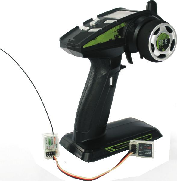
2 Contents 1 Introduction Services Special symbols Safety guide Transmitter specifications Receiver specifications Telemetry concentrator Sensors Binding Main function menu Main menu definition Connection diagram Functions interface D/R EPA Temperature Reverse ST CURVE TH CURVE A.B.S Models Fail Save MULTI OPT Timer Battery Reset Channel ADJ Monitor Speed Installing battery FCC statement Introduction Thank you for choosing the BER 3channels 2.4GHz Frequency-Hopping Spread Spectrum Digital proportional R/C for car and boat surface system. If it's your first use of a computerized radio system, this user manual will bring you easily to a new world of fun and sophistication. In all cases, please read carefully and completely this user manual as it contains all information to keep your safe and others. 2. Services If you encounter any problem during use, please referring to this manual. If the problem still persists, please contacting your local distributor or connect to our service to get support website: 3. Special symbols Please pay attention to the following symbols when they appear in the manual and read carefully.!!! Not following these instructions may expose the user to minor injuries and even to serious injuries. 4. Safety guide Not following these instructions may expose the user to serious injuries or death. Not following these instructions may expose others to serious injuries. Prohibited Mandatory Do not use it in the night or a lighting storm as the bad weather will 1
3 make the radio controller ( R/C ) out of control. Make sure moving direction of all servos be same with the operating direction. If not, please adjusting direction first. The shutdown sequence must be to first disconnect the receiver battery then to switch off the transmitter. If the transmitter is switched off while the receiver is still powered, it may lead to uncontrolled movement or engine start and may cause an accident. In particular, the 2.4G R/C FHSS system will affect the plane or the car nearby after you turn on the transmitter. Be sure to set the Fail Safe function on working situation, after finish F/S every time, please following turn off the transmitter, Don't turn on the transmitter halfway. Do not operate outdoors on rainy days, run through puddles of water or use when visibility is limited. Should any type of moisture (water or snow) enter any component of the system, erratic operation and loss of control may occur. Do not operate in the following places. -Near other sites where other radio control activity may occur. -Near people or roads.on any pond when passenger boats are present. -Near high tension power lines or communication broadcasting antennas. Interference could cause loss of control. Improper installation of your Radio Control System in your model could result in serious injury. Do not operate this R/C system when you are tired, not feeling well or under the influence of alcohol or drugs.your judgment is impaired and could result in a dangerous situation that may cause serious injury to yourself as well as others. Do not touch the engine, motor, speed control or any part of the model that will generate heat while the model is operating or immediately after its use. These parts may be very hot and can cause serious empyrosis. Always perform a operating range check prior to using. Problems with the radio control system as well as improper installation in a model could cause loss of control.(simple range test method) Have a friend hold the model, or clamp it down or place it where the wheels or prop cannot come in contact with any object. Walk away and check to see if the servos follow the movement of the controls on the transmitter. Should you notice any abnormal operation, and do not operate the model. Also check to be sure the model memory matches the model in use. Before turn on the power: Always checking the throttle trigger on the transmitter at the neutral position and TH trim too. When making adjustments to the model, do so with the engine not running or the motor disconnected. You may unexpectedly lose control and create a dangerous situation. The 2.4GHz radio band has a completely different behavior than previously used lower frequency bands. Keep always your model in sight as a large object can block the RF signal and lead to loss of control. The 2.4GHz RF signal propagates in straight lines and cannot get around objects on its path. Never grip the transmitter antenna when operating a model as it degrades significantly the RF signal quality and strength and may cause loss of control and danger Always turn on the transmitter first then the receiver. When turning off the system, always turn off the receiver first then the transmitter. This is to avoid having the receiver on itself as it may pick a wrong signal and lead to erratic servo movements. This is particularly important for electric powered models as it may unexpectedly turn on the motor and lead to injuries or death. 5. Transmitter Specifications


4 BER Introduction Transmitter specifications: Item: BER-TRC1 Channels: 3CH Model type: Car/Boat RF range: GHz Bands: NO. 208 RF power: less than 20 dbm 2.4G system: FHSS Code type: 2-FSK Sensitivity: 1024 Low voltage warning: (less than 4.4V) ST range: 84 (Around 42 ) TH range: 40 (F: 27;B:13) Charger port: Yes Power: 4.4V 8.6V Weight: 280g Size: 100*140*200mm Color: black Certificate: CE0678, FCC 3 Li-Po battery connecting line ( 2S, 3S, 4S and 6S ),Picture below. 6. Receiver Specifications RECEIVER SPECIFICATIONS Item: BER-RXV3 Channels: 3 Model type: Car/Boat RF range: GHz Bands: NO. 208 RF power: less than 20 dbm 2.4G system: FHSS Code type: 2-FSK Power: 4.4V - 8.6V Weight: 8g ANT length: 170mm Size: 13*20*30mm Color: White Rx Sensitivity: -105 dbm Certificate: CE0678, FCC 7. Binding Telemetry Concentrator Specs. Press BIND button CONCENTRATOR SPECIFICATIONS Item: BER-HCV1 Highly integrated Voltage acquisition module 3CH HOLD Measuring range: 1V 30V Temperature acquisition module Measuring range: Speed acquisition module Measuring range: 480RPM 50000RPM Sensors 1 Temperature sensors, two types for EP power or GP power. 2 Speed Sensor. 4 keeping 3CH button switch on transmitter(tx), the Tx led blue light flashing and buzzer sound 'B-B-B...'. It is in matching status. Then receiver(rx)connect power, the Rx green led light slow flash, keeping Rx BIND button till Rx green led light quick flash several times then slow flash, It shows bind successful. And turn off Tx 5


5 BER Introduction power and switch it on again. then Rx green led light become solid, It's in working status. NOTES: When binding processing, please don't put receiver antenna too close the transmitter antenna, far away 30CM better distance, too close the signal may jam. 8. Main Menu NOTES: This mark is a telemetry signal intensity ico. Telemetry system take transmitted signal priority, means when this mark disappear for interrupted. The transmitted signal always exist as long as in the effective range and specified conditions. (Testing found: existing signal interference, means within 1M existed other transmitters or interference source. The telemetry signal range is about 250M. No signal interference, means other transmitters or other interference sources far away more than 5M. the telemetry signal range about 500M.) 10. Connection diagram 1 EP car or boat connection diagram: 9. Main Screen


6 BER Introduction 2 GP car or boat connection diagram : 1. Press ENT to see FUNCTION menu. 2. Use the +/- Keys to select t h e E PA f u n c t i o n a n d press ENT. 3. Use the +/- Key to change the value when black box flashing 4. Press EXIT to save the setting and return to FUNCTION menu. TERMS: F-FORWARD, B-BACK, ST STEERING, TH THROTTLE, AUX 3CH TEMPERATURE 11. Function Interface D/R D/R is used to change the action range of steering servo when turning the steering wheel. Increasing D/R will make steering wheel action more sensitive. D/R adjusting value range : 0 120% Adjusted by the panel knob switch EPA Use this when performing left and right steering angle adjustments, throttle high side/brake side operation amount adjustment, and channel 3 servo up side/down side operation amount adjustment during linkage. EPA adjusting value range: %, default is 100% 8 This feature can know the motor or engine cooling fin real time temperature throughthe sensitive temperature sensor. You can set the max alarm temperature up to 150,minimum is 0. At the same time it can remember the maximum temperature at the whole procssing. Tx from turn on to swith off is a process. Swift off Tx the Max Temperature will clear to zero. 1 Press the "ENT" key to enter the FUNCTION menu 2 Use the + / - keys to select the TEM function, press ENT key to enter 3 Press ENT to select the setting 4 Use the + / - keys to set the value 5 Press EXIT to save and return to FUNCTION screen, Abbreviation: REAL TEMP - Actual temperature, WARN TEMP - Temperature alarm MAX TEMP Maximum temperature Note: When the temperature reaches the set value of real-time, high-temperature alarm will start and last for 10seconds.The maximum temperature of temperature sensor cable is 200, can not be used above. 9
7 11.03 REVERSE This function reverses the direction of operation of the servos related to steering, throttle, and channel 3 operation. 1 Press ENT to see FUNCTION menu 2 Use +/- Keys to select the REVERSE function and press ENT. 3 Press the + / - keys to select the setting 4 ENT key to switch to the REV or NOR 5 Press EXIT to save and return to FUNCTION screen, Abbreviations: ST -Steering, TH - throttle, AUX - Auxiliary Channel 3 This feature allows the end throttle and brake side direction servo operation to speed up or slow down, but does not affect the total amount of servo travel. TH CURVE RATE default value is 0%, the range of -100% - 100%; while a positive percentage, start fast, slow and vice versa. BACK RATE default value is 0% % % r a n g e ; p o s i t i v e percentage brake fast, slow and vice versa. 1 Press ENT to enter the FUNCTION menu, 2 Use the + / - keys to select the TH CURV function, press ENT key to enter the black box is not flashing, then through the + / - keys to select another spin. 3 Press EXIT to save and return to FUNCTION interface, Mode - Mode, RATE - ratio (throttle side), BACK RATE - brake side, ST CURVE This function is used to change the sensitivity of the sites around the steering servo, the servo does not affect the total amount of the stroke. Adjusting to positive hundred percent, the rotation center position will be sensitive. To hundred percent negative direction, rotation ends sensitive. When the setting is not identified or characteristics of the model is ambiguous, the value starts at 0%. 1 Press ENT to enter the FUNCTION interface. 2 Use the + / - keys to select the ST CURV function, press ENT key to enter the 3 Use the + / - keys to set the value 4 Press EXIT to save and return to FUNCTION menu interface, Direction of the curve adjustment range: - 100% - 100%, default: 0% (linear) Mode - Mode, Rate Ratio ABS ABS is a kind of anti-lock braking system security control, both ordinary braking system, but also to prevent wheel lockup, so that the model car in the braking state can still turn, guarantee or other large four-wheel drive model car, brake movement direction at high speed stability, prevent skidding and deviation TH CURVE 1 Press ENTER to enter the FUNCTION interface, 2 Use the + / - keys to select the ABS function, press ENT to enter through ENT key to select ON / OFF
 Step with PT entry, select and set WD items.")
8 3 Press the + / - keys to select PT items, choose good press ENT key, the black box flashes by + / - keys to adjust the value. After this adjustment, press the ENT key to confirm. When the black box is not flashing, then through the + / - keys to select an item to adjust. Range: 0% - 100% (the default value is 0%) Step with PT entry, select and set WD items. Range: 0% - 100% (the default is 0%) Step with PT entry, select and set CY items. Range: 0-30 (default is 0) Step with PT entry, select and set DT items. Range: 0-5 (default is 0) Press EXIT to save and return to FUNCTION interface, Notes abbreviated terms: PT - Position of the throttle trigger when ABS works. WD - Brake return amount. CY - Cycle speed. ABS operation cycle. The smaller the value, the faster the cycle. DT - From the braking point back to the time of the release point. and pressing ENT key to select ON / OFF. Use the + / - keys to select SET 3 Put the throttle trigger to set TH f/s value and press ENT saved Successful appears on the screen, F/S setting successfully. 4 Press EXIT to save and return to FUNCTION screen, TH throttle values : 1000US US, 1500US is default neutral position. SET DATA: To be setted F/S valuve. NOTES: For your safety, when has setted F/S function. Before playing, checking F/S function work is very necessary! MODEL This function is used to select the model memory, supports six sets of memory. 1 Press ENTER to enter the FUNCTION interface, 2 Use the + / - keys to select the module memory function, press ENTER 3 Use the + / - keys to select the move instruction arrows. 4 Press ENTER to save the selection. 5 Press EXIT to save and return to FUNCTION screen, Note: When change modes, servos delay may happen, you can solve this problem by re-switch on transmitter FAIL SAVE If the signal loss occurs, the receiver can set the value of throttle servo to the fixed. 1 Press ENT to enter the FUNCTION interface 2 Use the + / - keys to select the FAIL SAFE function, press ENT key to enter, MULTI OPT This function is used to turn on or switch off remote control buzzer. Turning on the TH HOLD and achieve the 2CH and 3CH special mix function. 1 Press ENT to enter the FUNCTION interface. 2 Use the + / - keys to select the function, press ENT key to enter 2 Use the +/- key to select function. 3 Press EXIT to save and return to FUNCTION screen NOTES: The TH HOLD adjust value is setting 100 corresponding the value of 40% of the maximum throttle value. Before the setted throttle value put the triger, the throttle slow acceleration till to setted throttle value. the setted throttle value is minimum throttle. As long as no brake, put the trigger in neutral positon, the throttle keep the setted throttle. When setted the TH HOLD, brake or swith on the Tx need put the trigger to start the setted throttle. 2, The 2CH and 3CH mix control. The 3CH servo just unilateral movement. This special function used for cars or motorbikes with brake disk system. The reverse to be justed in funcion reverse function
9 TIMER By UP TIMER, DOWN TIMER, addend or countdown timer. How to set: 1 Press ENT to enter the FUNCTION interface 2 Use the + / - keys to select the TIMER function, press ENT key to enter 3 Press ENT to select ON / OFF 4 Use the + / - keys to select MODE, choose good press ENT key, the black box flashes by + / - keys to select the U / D. 5 After this adjustment, press the ENT key to confirm. When the black box is not flashing, through the + / - keys to select another spin. 6 Press EXIT to save and return to FUNCTION MENU; NOTE: Timer begin with the pull of the throttle trigger. Without changing the throttle trim, or throttle curve, the slight pull the trigger timer will begin counting. If changes in these parameters, pull or not may cause timing function start. Time out the buzzer will issue a "B-B-B" audible sound which stops after 10 seconds BATTERY This feature can know the vehicles real-time voltage change, 1 Press ENT to enter the function interface 2 Use the + / - keys to select BATTERY function, press ENT key to enter 3 Press the ENT button to select one 4 Press EXIT to save and return to FUNCTION interface, 1.EP cars or boats, digital system will automatically identify low voltage alarm of 2S, 3S, 4S and 6S Li-Po battery (the default is each Li-Po battery voltage lower than 3.5V, the alarm will be start after continue some seconds), Additional setting voltage alarm is not requires. If you are using 4 or 5 Ni-MH battery to control the gas car and gas boat, then you need to choose, if you do not choose, there will be situations voltage disorder alarms and not show on the main menu. 2.4 or 5 Ni-MH battery voltage display is entered directly through the receiver, no additional connection, just inside this menu, select the corresponding cell numbers and need to connect the concentrator BER-HCV1.Detection of Li-Po battery should be through the battery connecting line into BER-HCV1 VOL hub as above connection diagram shown: ( Do pay attention to the battery pole. Do not connect reverse ) RESET return to FUNCTION screen, CHANNEL ADJ All settings can be reset to the factory settings, including different memory modules, all previous settings will be restored to factory settings. 1 Press ENT to enter the FUNCTION interface 2 Use the + / - keys to select RESET function, press ENT key to enter 3 Press the + / - keys to select YES and press ENT reset factory sitting. 4 Press EXIT to save and CHANNEL ADJ is Channel adjustment. NOTE: This feature is for the factory calibration(or professional player). When your R/C is under normal use, please do not enter. But when you find servo motion is abnormal or if you change potentiometers, it will be needed. Please enter the function MONITOR to check each channel dynamic value status (see at the state of the factory settings). If normal, Do not calibrate. If abnormal please calibrate as follow:


10 Press ENT into figure1 (from left), don't touch neutral position of steering and throttle, press ENT button, the neutral position has calibrated and into Figure2, moving the direction of steering to the end-point maximum position, and return back neutral position not move. Then put throttle trigger to end-points of two sides and return back neutral position not move. Movement no sequence, no numbers requirement, multiple or first mover throttle has no effect, the premise is each movement must be to the end-point position. Then press ENT into figure3, showing channel calibration done, press EXIT to save and exit MONITOR This function is to display the channel running status. And to check whether the calibration of function channels ADJ is correct or wrong. The output pulse is about 1000US US. The median point of the pulse is about 1500US. First passed function RESET re-set system. Viewing neutral parameters. ST display about is 1500US (allow showing numbers a slight fluctuation) TH display about is 1500US (allow showing numbers a slight fluctuation) Pulling the throttle trigger to two ends display the value about 1000US -2000US. TH output pulse is normal. Turn the steering to the left and right ends, by adjusting the D/R knob, the value displayed about 1000US-2000US. ST output pulse is normal AUX displayed value is at around 1000US US end-point value. Note: 1.Allowing showing numbers a slight fluctuation. It is normal. 2.if these values are displayed above. Please do not run function SPEED This function is to test wheel speed by light-sensor. It is important to note that the use of light-sensor need to outdoors with bright areas which makes the test result more accurate. And you could not install light-sensor in the shadow or backlight. It also requires specification of the impeller blades are organized distribution, standardized impeller blades shown in the below left picture. How to install. Light-sensor should be installed verticality to the wheel impeller blades ( Principle of operation: light sensor vertical light is blocked periodically in order to calculate the wheel speed), the installation distance in accordance with the best lighting effects. The vertical best distance (1CM-4CM). If it is five impeller blades, setting Blade sum by pressing + / - keys to five. The largest selection of impeller blade support 12. This supports high-speed rotating speed, low speed test is not supported, if it is two pieces of the impeller blades required minimum rotate speed achieve 480RPM. 12 impeller blades max support testing rotate speed up to 50,000RPM. At the same time it can remember the max speed at the whole procssing. Tx from turn on to swith off is a process. Switch off the Tx the Max Speed will clear to zero. NOTES: When the supply voltage of the receiver is lower than 5.2V, the supply voltage is not enough to the light sensing probe, the test of speed will be not accurate, while different fixed number will be shown on screen time to time. 12, Installing battery 1,The transmitter battery standard installed use four dry batteries or four Ni-MH rechargeable batteries. Because of the special design of the battery box, so the battery cover makes installation a little tight, you can help other artifacts gently force open the battery cover. 2, The process of installing the battery, if the battery box is removed, put it back again, do not suppress the battery box power line, otherwise cause the battery cover is not easy to close. 3, For customers DIY the battery, transmitter maximum support 8.6V voltage, so using 2S Li-Po battery should pay attention to the positive and negative pole correct connect JST connector base. Especially the charge must be used balance charger, so as to ensure the relative safety of charge 13 FCC Statement
11 FCC Statement This equipment has been tested and found to comply with the limits for a Class B digital device pursuant to part 15 of the FCC rules. These limits are designed to provide reasonable protection against harmful interference in a residential installation. This equipment generates, uses and can radiate radio frequency energy and, if not installed and used in accordance with the instructions, may cause harmful interference to radio communications. However, there is no guarantee that interference will not occur in a particular installation. If this equipment does cause harmful interference to radio or television reception, which can be determined by turning the equipment off and on, the user is encouraged to try to correct the interference by one or more of the following measures: - Increase the separation between the equipment and receiver. - The equipment into an outlet on a circuit different from that to which the receiver isconnected. - Consult the dealer or an experienced radio/tv technician for help. To assure continued compliance, any changes or modifications not expressly approved by the party responsible for compliance could void the user's authority to operate this equipment. (Example use only shielded interface cables when connecting to computer or peripheral devices). This equipment complies with Part 15 of the FCC Rules. Operation is subject to the following two conditions: (1) This device may not cause harmful interference, and (2) This device must accept any interference received, including interference that may cause undesired operation
Thank you for purchasing our product, an ideal radio system for beginners or experienced users alike.
 Thank you for purchasing our product, an ideal radio system for beginners or experienced users alike. Read this manual carefully before operation in order to ensure your safety, and the safety of others
DIGITAL PROPORTIONAL RADIO CONTROL SYSTEM INSTRUCTION MANUAL
 - DIGITAL PROPORTIONAL RADIO CONTROL SYSTEM INSTRUCTION MANUAL - Thank you for purchasing our product, an ideal radio system for beginners or experienced users alike. Read this manual carefully before
3PRKA. 3-channel, FHSS Radio control system for Car INSTRUCTION MANUAL 1M23N Digital Proportional R/C System
 3PRKA 3-channel, FHSS Radio control system for Car 1M23N25002 INSTRUCTION MANUAL R Digital Proportional R/C System Thank you for purchasing a Futaba FHSS 3PRKA 2.4GHz system. This system is based on the
Instruction Manual. item no. : SPR0113
 Instruction Manual item no. : SPR0 . Introduction... p.. Safty Guides... p.. Battery Charging notes... p.4 4. Transmitter and Receiver parameters...p.5 - p.6 5. Receiver Connectivity...p.7 6..4G Operation
INSTRUCTION MANUAL. Digital proportional radio control system. Digital proportional radio control system. Copyright 2013 Absima GmbH
 INSTRUCTION MANUAL Digital proportional radio control system Copyright 2013 Absima GmbH WARNING: This product is only for 15 years old or above Thank you for purchasing our product, an ideal radio system
TS6 2.4GHz 6CH Radio Control System. Instruction manual. No.8610
 TS6 2.4GHz 6CH Radio Control System Instruction manual No.8610 Introduction Congratulations on your purchase of the Innovator TS6 + advanced 6 Channel 2.4GHz spread spectrum radio control system. This
CRUX II/BTGPS USER GUIDE. Model:D1598
 CRUX II/BTGPS USER GUIDE Model:D1598 0 Federal Communication Commission Interference Statement This equipment has been tested and found to comply with the limits for a Class B digital device, pursuant
12V Victor 888 User Manual
 The Victor speed controllers are specifically engineered for robotic applications. The high current capacity, low voltage drop, and peak surge capacity make the Victor ideal for drive systems while its
We appreciate your purchase of this new Airtronics Please note that the MX-3FG is designed for comfort and
 We appreciate your purchase of this new Airtronics Please note that the MX-3FG is designed for comfort and MX-3FG Frequency Hopping Spread Spectrum precise control of all types of model cars and boats.
FOR AVLEX ONLY MT-24A. User Guide. 2.4 GHz Digital Stationary Transmitter
 2.4 GHz Digital Stationary Transmitter User Guide All rights reserved. MN 017/05 Do not copy or forward without prior approvals MIPRO. Specifications and design subject to change without notice. 2 CE5
Quick Start Guide. Antenna Alignment Tool AIMWLLR0-35. QSG rev 7 AIMWLLR0-35 [NRB-0200] QSG.indd 1
![Quick Start Guide. Antenna Alignment Tool AIMWLLR0-35. QSG rev 7 AIMWLLR0-35 [NRB-0200] QSG.indd 1](/thumbs/86/94268876.jpg "Quick Start Guide. Antenna Alignment Tool AIMWLLR0-35. QSG rev 7 AIMWLLR0-35 [NRB-0200] QSG.indd 1") Quick Start Guide Antenna Alignment Tool AIMWLLR0-35 QSG-00097 rev 7 AIMWLLR0-35 [NRB-0200] QSG.indd 1 Welcome This quick start guide is designed to familiarize you with the features and use of the NetComm
Quick Start Guide Antenna Alignment Tool AIMWLLR0-35 QSG-00097 rev 7 AIMWLLR0-35 [NRB-0200] QSG.indd 1 Welcome This quick start guide is designed to familiarize you with the features and use of the NetComm
Fly-Dream 2.4GHz V3 Radio Control System
 Fly-Dream 2.4GHz V3 Radio Control System Thank you for purchasing our Fly-Dream 2.4GHz V3 Radio Control System. We are sure you will enjoy it. The following notes will guide you through the simple set
RF (RADIO FREQUENCY) WIRELESS PENDANT
 WIRELESS PENDANT") NOTE: The following information is an addition to the Operation section in the lift system owner s manual. It describes the RF wireless pendant for your lift system. You must read the lift system owner
NOTE: The following information is an addition to the Operation section in the lift system owner s manual. It describes the RF wireless pendant for your lift system. You must read the lift system owner
EXMITTER -- Professional Remote Control Products Expert
 EXMITTER -- Professional Remote Control Products Expert WARNING The following terms are used throughout the product literature to indicate various levels of potential harm when operating this product.
Wireless Color Weather Station
 Wireless Color Weather Station INSTRUCTION MANUAL MODEL: C85845V3 DC: 120518 FIND MANUALS, FAQS, AND MORE UNDER THE SUPPORT TAB HERE: bit.ly/c85845v3 TABLE OF CONTENTS 3. Power Up 3. LCD Features 4. Buttons
 ON Ergonomic Pistol Grip Design 2 Channel AM Proportional System 2 Channel Servo Reversing Switches 2 LED Battery Status Indicator Nicad Battery Charging Jack MADE IN PHILIPPINES NOR REV NOR REV ON I.
USER MANUAL MODEL: BM-162
 USER MANUAL MODEL: BM-162 Parents Unit: A. Name Power ON/OFF Key Music Key PTT Key Volume - Key Microphone Power & Low battery indicator LCD display Volume + Key Night Light and torch Key Speaker -Belt
SKY-6601 INSTALLATION AND OPERATING INSTRUCTIONS
 SKY-6601 INSTALLATI AND OPERATING INSTRUCTIS INTRODUCTI This SKYTECH remote control system was developed to provide a safe, reliable, and user-friendly remote control system for gas heating appliances.
Alchemy Systems L.P. SISTEM Radio Frequency Remote Control(8015-2R) & receiver(8015-2b) User Guide. Version: 2.4. Prepared by: Carlos A Acosta
 & receiver(8015-2b) User Guide. Version: 2.4. Prepared by: Carlos A Acosta") Alchemy Systems L.P. 8015 Shoal Creek Blvd., Suite 100 Austin, TX 78757 tel: 512-637-5100 fax: 512-637-5168 www.alchemysystems.com Alchemy Systems L.P. SISTEM Radio Frequency Remote Control(8015-2R) &
Alchemy Systems L.P. 8015 Shoal Creek Blvd., Suite 100 Austin, TX 78757 tel: 512-637-5100 fax: 512-637-5168 www.alchemysystems.com Alchemy Systems L.P. SISTEM Radio Frequency Remote Control(8015-2R) &
100A PWM Input Pulse (High Time) 1 2 ms Nominal ms max PWM Input Rate (Period) ms PWM Output Chop Rate (Switching Frequency)
 1 2 ms Nominal ms max PWM Input Rate (Period) ms PWM Output Chop Rate (Switching Frequency)") The Victor SP is a speed controller designed through collaboration between VEX Robotics (VEX.com) & Cross the Road Electronics () that allows for fine control and high performance of brushed DC motors
The Victor SP is a speed controller designed through collaboration between VEX Robotics (VEX.com) & Cross the Road Electronics () that allows for fine control and high performance of brushed DC motors
4YWD 4-channel, FHSS Radio control system for EP Car INSTRUCTION MANUAL 1M23N Digital Proportional R/C System
 4YWD 4-channel, FHSS Radio control system for EP Car INSTRUCTION MANUAL 1M23N28702 R Digital Proportional R/C System Thank you for purchasing a Futaba 4YWD FHSS 2.4GHz system. This system is based on the
R PROFLAME Instruction Book Collection
 9.956.028 R00 584 PROFLAME Instruction Book Collection 4-17 18-29 584 PROFLAME System 30-39 Appendix: DIP SWITCH NUMBER (0=ON 1=OFF) 40-41 4-17 Fig. 1 The SIT is a device that allows, in conjunction with
CCR24T CCR24R. User s Guide WIRELESS TRANSMITTER SYSTEM WARRANTY SERVICE CARD WARRANTY CARD
 WARRANTY SERVICE CARD WARRANTY CARD PRODUCT NAME Wireless Transceiver System PERIOD MODEL NAME CCR24GEN YEAR PURCHASE DATE.. 200_ From the date of WARRANTY PERIOD.. 200_ purchase. CUSTOMER S ADDRESS :
Blue Point Engineering Inc.
 Engineering Inc. ireless Radio Control of Puppets Setup Overview RF Control C Pointing the ay to Solutions! Hardware Setup Overview Page 1 Servo No.1 Servo No.2 Control Signal Line RX8ch1,2 Servo Board
S ENSORLINK INSTALLATION MANUAL
 S ENSORLINK INSTALLATION MANUAL The SensorLink Transmitter (#7610) and SensorLink Receiver (#7611) are designed to work with Davis Instruments Weather Monitor II and the Weather Wizard III to enable wireless
DJT RC Transmitter Module 2.4 GHz Two-Way Series
 Manual Rev.0.1-5.05.201 2 made by David LABURTHE dlaburthe@free. fr DJT RC Transmitter Module 2.4 GHz Two-Way Series U S E R ' S G U I D E FrSky Electronic Co., Ltd - No. 1, Huize Road, Wuxi, 21 4081,
CX-CT6A INSTRUCTION MANUAL. Computer Transmitter. Digital Propotional Radio Control System. 6 channel Radio Control System
 CX-CT6A INSTRUCTION MANUAL 6 channel Radio Control System Digital Propotional Radio Control System www.copterx.com Copyright 2008 KY MODEL Company Limited. MENU Table of content.........................................................................
Blue Point Engineering
 Overview Blue Point Instruction Board 2-CH Boards, Terminal Block and Ribbon Cable I Type: RF Radio (315 MHz) 1-2 Channels (FCC Part 15 Compliant Components). Operating Voltage: 6-15 VDC @ 1 Amp (Wall
IMPORTANT: READ AND UNDERSTAND ALL INSTRUCTIONS BEFORE BEGINNING INSTALLATION
 INSTALLATI INSTRUCTIS Model: RB-G-K10 IMPORTANT: READ AND UNDERSTAND ALL INSTRUCTIS BEFORE BEGINNING INSTALLATI The Miller Edge RBand Monitored Gate Edge Transmitter/Receiver system is intended to provide
Instruction Manual. 2.4 GHz DIGITAL PROPORTIONAL 9-CH RADIO CONTROL SYSTEM. No.8901 JC7405
 2.4 GHz DIGITAL PROPORTIONAL 9-CH RADIO CONTROL SYSTEM Instruction Manual No.8901 FCC ID: VEJ-COUGARGP3 thundertiger.com Manufactured / Hersteller : Thunder Tiger Corp.(Ningbo) 28 Jin-Feng Road, Liang
Husqvarna Fleet Services Machine Sensor. Machine Sensor Please read these instructions carefully before using the device. Original instructions
 Husqvarna Fleet Services Machine Sensor Machine Sensor Please read these instructions carefully before using the device. Original instructions Safety and Regulatory Information IMPORTANT: A complete User
IMPORTANT: THIS DEVICE MUST BE PROFESSIONALLY INSTALLED. READ AND UNDERSTAND ALL INSTRUCTIONS BEFORE BEGINNING INSTALLATION.
 INSTALLATI INSTRUCTIS Model: RB-G-K10 IMPORTANT: THIS DEVICE MUST BE PROFESSIALLY INSTALLED. READ AND UNDERSTAND ALL INSTRUCTIS BEFORE BEGINNING INSTALLATI. The Miller Edge RBand Monitored Gate Edge Transmitter/Receiver
Wireless Pressure Station with Backlight
 Wireless Pressure Station with Backlight FORECAST RELATIVE PRESSURE PRESSURE HISTORY inhg -24h -18h -12h -9h- 6h -3h0 h INDOOR For online video support: http://bit.ly/laxtechtalk Model: 308-1417BL DC:
MTC-2 highlight features: ACU highlight features: Contents. MTC-2 and ACU User Manual V5.1
 MTC-2 can work alone as a twin motor ECS (electronic speed controller) for RC tanks. When the ACU (auxiliary control unit) is connected, it can also control turret rotation, gun elevation, gun firing,
System Requirements: D-Link Systems, Inc.
 System Requirements: Minimum System Requirements: CD-ROM Drive Computers with Windows, Macintosh, or Linux-based operating systems Installed Ether net Adapter Internet Explorer version 6.0 or Netscape
TM14-2.4G/R6014FS/R608FS Radio Control Instruction Manual
 TM14-2.4G/R6014FS/R608FS Radio Control Instruction Manual INTRODUCTION Thank you for purchasing a FutabaR digital proportional R/C system. In order for you to make the best use of your system and to use
WIRELESS TEMPERATURE S TATION I NSTALLATION MANUAL
 Wireless Temp Page 1 Thursday, December 7, 2000 2:09 PM WIRELESS TEMPERATURE S TATION I NSTALLATION MANUAL The Wireless Temperature Station is for use with Wireless Vantage Pro TM. COMPONENTS The Wireless
Wireless AC Circuit Identifier
 User's Guide Wireless AC Circuit Identifier Models RT30 and RT30-E 99 Washington Street Melrose, MA 02176 Phone 781-665-1400 Toll Free 1-800-517-8431 Visit us at www.testequipmentdepot.com Back to the
Instruction Manual. for Media Monkey. 1
 TM TM Instruction Manual for Media Monkey www.audioaperemote.com 1 Congratulations on acquiring your fine Audio Ape product Let s dive right in, getting up and running is a snap. Here are the components:
ORiNOCO AP-4000MR-LR and AP-4900MR-LR Access Points Safety and Regulatory Compliance Information
 IMPORTANT! Visit http://support.proxim.com for the latest safety and regulatory compliance information for this product. ORiNOCO AP-4000MR-LR and AP-4900MR-LR Access Points Safety and Regulatory Compliance
Blue Point Engineering Inc.
 nc. Wireless Radio Control of Puppets Setup Overview RF Control C Hardware Setup Overview Servo No.1 Servo No.2 Control Signal Line RX8-ch1,2 Servo Board WZ-12 RX8-ch3,4 Servo Board WZ-12 Power Line DC
THE HUBSAN X4 DESIRE
 Ages 14+ READ THE INSTRUCTION MANUAL CAREFULLY PLEASE VISIT WWW.HUBSAN TO UPGRADE THE HUBSAN X4 DESIRE ITEM NO.: H502E ARM/DISARM MOTORS, SEE PAGE 06 RTH FUNCTION, SEE PAGE 09 COMPASS CALIBRATION, SEE
M508 GPS Tracking Device
 M508 GPS Tracking Device (GPS+GPRS+GSM) Product Manual Edition 1.3 Copyright 10 th Oct., 2009 GATOR GROUP CO.,LTD. All rights reserved. http://www.gatorcn.com China Printing ADD: 312# Ansheng Building,Xixiang
INSTALLATION AND OPERATION MANUAL
 RADIO/CAN REMOTE CONTROL SYSTEM -PRELIMINARY- INSTALLATION AND OPERATION MANUAL SDP GREEN 3B1151AJ.doc September 3, 2009 AP INDEX DESCRIPTION... 2 TRANSMITTER AND RECEIVER SYNCHRONIZATION... 3 INDICATOR
YGE ProgCard II - Programming Card
 YGE ProgCard II - Programming Card With the programming card, we offer an easy to use programming unit, with which all our ProgCard II capable speed controllers can have their individual functions changed.
IMPORTANT: THIS DEVICE MUST BE PROFESSIONALLY INSTALLED READ AND UNDERSTAND ALL INSTRUCTIONS BEFORE BEGINNING INSTALLATION
 INSTALLATI INSTRUCTIS Models: RB-G-K10, RB-TX10 IMPORTANT: THIS DEVICE MUST BE PROFESSIALLY INSTALLED READ AND UNDERSTAND ALL INSTRUCTIS BEFORE BEGINNING INSTALLATI The Miller Edge RBand Monitored Gate
10. Racers Tips. - The most important thing to remember is to have fun!
 8. Troubleshooting Guide Question: I installed the batteries in my transmitter, but the power lights do not come on: Answer: - Check that the batteries are properly installed by checking the polarity (+
Detrum GAVIN-8C Transmitter
 Motion RC Supplemental Guide for the Detrum GAVIN-8C Transmitter Version 1.0 Contents Review the Transmitter s Controls... 1 Review the Home Screen... 2 Power the Transmitter... 3 Calibrate the Transmitter...
Wireless Programmer for Wireless Sensor System
 R INSTALLATION AND OPERATION INSTRUCTIONS Wireless Programmer for Wireless Sensor System FOR PLATINUM CONTROLS WITH COMMUNICATION Connect to other Wireless units LED Green = in operation Red = charging
Instruction Manual Please read carefully before use and keep for future reference.
 Easy-Read Dual Alarm Clock with Daily Repeat, Bluetooth, and USB Charge Port NRC-181 Instruction Manual Please read carefully before use and keep for future reference. Important Safety Information CAUTION
MPRF01 Wireless 5uA Inductive Proximity Sensor RF System
 System Description; The MPRF01 is a simple ready to use Wireless Inductive. No programming is required; just insert 2, (1.5V) AA batteries into the Transmitter module. The RF receiver module is connected
Schwinn MPower Echelon Console + Power
 Schwinn MPower Echelon Console + Power 2013 Core Fitness, LLC, dba StairMaster. All rights reserved. and indicates a trademark or registered trademark. Core Fitness, LLC trademarks include Schwinn, A.C.,
Connevans.info. DeafEquipment.co.uk. This product may be purchased from Connevans Limited secure online store at
 Connevans.info Solutions to improve the quality of life Offering you choice Helping you choose This product may be purchased from Connevans Limited secure online store at www.deafequipment.co.uk DeafEquipment.co.uk
NEO CAR AUDIO. Neo AUXiN AUX INPUT INTERFACE. Instruction Manual
 NEO CAR AUDIO Neo AUXiN AUX INPUT INTERFACE Instruction Manual IMPORTANT NOTE Neo AUXiN Dip switch positions MUST be set BEFORE any other step is taken. Otherwise, the kit will not operate properly. See
INSTRUCTION MANUAL. 2 Channel Digital Proportional R/C System 1M23N06406
 INSTRUCTION MANUAL 2 Channel Digital Proportional R/C System 1M23N06406 R Thank you for purchasing a Futaba ATTACK 2ER. Before using your ATTACK 2ER, read this manual carefully and use your R/C set safely.
Interface Manual Tank Level Float Stick System
 1 Interface Manual Tank Level Float Stick System SignalFire Model: Sentinel-FS-3BIS The SignalFire Sentinel Float Stick Node is an Intrinsically Safe device with the following features: - Standard SignalFire
Keycards come with an imbedded RFID chip and antenna, there is no battery in the keycards. The keycards are encrypted and only
 Index Keycards 02 The following is a description of the type of Keycards and function 03 Programming and Initialization of the RFID Lock 04 Procedure for Initialization 05 Programming- Adding Keycards
Atomic Forecast Station with Moon Phase
 Atomic Forecast Station with Moon Phase For online video support: http://bit.ly/laxtechtalk Model: S84107 Instruction Manual DC: 080817 Welcome to the La Crosse Technology family! We hope you enjoy your
Remote Control Outlets Operating Instructions
 Remote Control Outlets Operating Instructions - FOR INDOOR OR OUTDOOR USE - IMPORTANT SAFEGUARDS Signal Word Definitions NOTE: These are general definitions only; all may not pertain to the actual product
Table of Contents. Mounting Diagram.. Wiring Information.. Setting the STR 1000 as a Repeater or a Transmitter. STR 1000 Frequently Asked Questions..
 STR 1000 Series Repeater Installation Manual (V 3.0) Table of Contents MOUNTING Mounting Diagram.. Page 2 WIRING INFORMATION Wiring Information.. Page 3 Setting the STR 1000 as a Repeater or a Transmitter.
Quick Guide. FCC/IC: MHz CE: MHz
 Quick Guide FCC/IC: 340.00-354.00 MHz CE: 433.42-434.42 MHz IMPORTANT: FCC/Canada frequency radios are NOT compatible with CE frequency radios and vice versa. PocketWizard.com/wheretobuy/frequency The
Manual Unihan UPWL6025
 Manual Unihan UPWL6025 Federal Communications Commission Statement This device complies with FCC Rules Part 15. Operation is subject to the following i. This device may not cause harmful interference,
Driveway Alarm INSTALLATION MANUAL
 WIRELESS ACCESS CONTROLS Driveway Alarm INSTALLATION MANUAL Mounting post Transmitter Receiver Transformer Sensor Kit Includes: Transmitter Module Sensor Receiver Transformer Mounting post (3 pieces) Installation
Schlage Control Smart Locks
 Schlage Control Smart Locks with Engage technology User guide Schlage Control Smart Locks with Engage technology User Guide Contents 3 Warranty 4 Standard Operation 4 Operation from the Inside 4 Operation
Mag 3/6 System. Manual.
 Mag 3/6 System Manual www.undergroundmagnetics.com 1: Introduction....1 1 2: Caution.... 2 2 3: FCC Compliance Statement.. 3 4: Tips for Reading this Manual....3 4 5: Preface....4 5 6: System Highlights....6
Radio Micro Force Manual v1.1
 Radio Micro Force Manual v1.1 Preston Cinema Systems 1659 Eleventh Street Santa Monica CA 90404 tel 310-453-1852 fax 310-453-5672 www.prestoncinema.com Table of Contents 1. Description 2. Operation 3.
EXMITTER -- Professional Remote Control Products Expert
 EXMITTER -- Professional Remote Control Products Expert WARNING The following terms are used throughout the product literature to indicate various levels of potential harm when operating this product.
MTC-2 highlight features: ACU for Flakpanzer Gepard highlight features: Contents. MTC-2 and ACU User Manual V4.2 (Flakpanzer Gepard Version)
") This manual is written for the ACU for Flakpanzer Gepard. There are some modifications on usage of servo and LED ports. Please also notice that GSU (gun stabilize unit) is not supported. MTC-2 highlight
This manual is written for the ACU for Flakpanzer Gepard. There are some modifications on usage of servo and LED ports. Please also notice that GSU (gun stabilize unit) is not supported. MTC-2 highlight
On-Line Cardio Theater Wireless Digital Transmitter Installation and Instruction Manual
 On-Line Cardio Theater Wireless Digital Transmitter Installation and Instruction Manual Full installation instructions accompany your Cardio Theater equipment order. This On-Line version of our Installation/Instruction
XD-V30 Digital Wireless System
 XD-V30 Digital Wireless System Pilot s Handbook Manuel de pilotage Pilotenhandbuch Pilotenhandboek Manual del Piloto 取扱説明書 See www.line6.com/manuals for Advance Guide 40-00-0286 Advanced Users Guide available
Precaution of Safety. Before using this product, check that you have all of the following items. If any items are missing, please contact dealer.
 USER MANUAL 1 2 Content Before using this product, check that you have all of the following items. If any items are missing, please contact dealer. Introduction Thank you for purchasing HobbyKing.com HK-7X
Remote Control Extender AUDIO / VIDEO DEVICES EXTENDING SYSTEM
 Remote Control Extender AUDIO / VIDEO DEVICES EXTENDING SYSTEM MODEL NO.: AWX 701-A/AWX 701-B/AWX 701-C OPERATION MANUAL Remote Control Extender AUDIO / VIDEO DEVICES EXTENDING SYSTEM MODEL NO.: AWX 701-A/AWX
Combo Scanner. User Manual
 Combo Scanner User Manual I. Unpack the Combo Scanner Backlight Holder Combo Scanner Business card Fixture Photo/Business Card Holder User Manual Quick Installation Guide Note This Combo Scanner supports
Wireless Pressure Station
 Wireless Pressure Station FORECAST RELATIVE PRESSURE PRESSURE HISTORY inhg -24h -18h -12h -9h- 6h -3h0 h INDOOR For online video support: http://bit.ly/laxtechtalk Model: 308-1417 DC: 111517 Table of Contents
Manual Unihan UPWL6580
 Manual Unihan UPWL6580 Federal Communications Commission Statement This device complies with FCC Rules Part 15. Operation is subject to the following i. This device may not cause harmful interference,
USER MANUAL. Sens it SENS IT 2.4
 USER MANUAL www.sensit.io Sens it SENS IT 2.4 SUMMARY SAFETY INSTRUCTIONS 4 I. CONTENT OF THE PACK 4 II. PRESENTATION 5 III. HOW TO START 8 IV. TECHNICAL SPECIFICATIONS 9 V. WARNING STATEMENTS 10 VI. CREDITS
Wireless SingStar Microphone Instruction Manual
 Wireless SingStar Microphone Instruction Manual 2008 Sony Computer Entertainment Europe. SingStar is a trademark or a registered trademark of Sony Computer Entertainment Europe. 2, PLAYSTATION and PlayStation
MTC-2 highlight features: ACU highlight features: Contents. MTC-2 and ACU User Manual V4.0
 MTC-2 can work alone as a twin motor ECS (electronic speed controller) for RC tanks. When the ACU (auxiliary control unit) is connected, it can also control turret rotation, gun elevation, gun firing,
User Manual. Product Name:tablet Model Name:TM800A740M Brand Name:NuVision. Manufacture:Shenzhen Vastking Electronic Co.,LTD.
 User Manual Product Name:tablet Model Name:TM800A740M Brand Name:NuVision Manufacture:Shenzhen Vastking Electronic Co.,LTD. FCC Warning This device complies with part 15 of the FCC
HY737 Walkie talkie for kids
 HY737 Walkie talkie for kids ANTENNA SWITCH, VOLUME KNOB RED STATUS LIGHT MIC SPEAKER WWW.THEIPAR.CC WILLIAMWANG18@OUTLOOK.COM FCC ID: 2AJEM-HY737 ANTENNA ANTENNA SWITCH, VOLUME KNOB BELT BUCKLE PUSH TO
INSTALLATION MANUAL FOR SAL SERIES WIRELESS CLOCKS SPECIFICATIONS
 INSTALLATION MANUAL FOR SAL SERIES WIRELESS CLOCKS SPECIFICATIONS Time base: Quartz Power input: Battery (2 D cell) : Part # SAL-1BS-12R-0 95 135 VAC / 60 Hz: Part # SAL-1BS-12R-1 7 28 VAC / 60 Hz: Part
What is Moto? bring happiness to life. The lights Pressuresensitive
 User Manual 1 bring happiness to life What is Moto? Moto tiles are a tool for physical play. They are included under the product category Playware, which combines robotics with play to create products
RCR-24 中文 GB. Version 1
 RCR-24 中文 GB Version 1 GB Please note not all AC adapters are alike. The AC adapter that is included with this radio is designed to be used exclusively with this device. Do not use an AC adapter that differs
Copyright Graupner/SJ GmbH. Manual. mz-4 2 channel HoTT 2,4 GHz transmitter No. S1031
 Copyright Graupner/SJ GmbH EN Manual mz-4 2 channel HoTT 2,4 GHz transmitter No. S1031 Index Introduction... 4 Service Centre... 4 Intended use... 5 Package content... 5 Technical Data... 5 Symbols explication...
WLS-5500 Receiver (KSF & W26)
") WLS-5500 Receiver (KSF & W26) Installation Manual DN1869-0912 Warning! This manual contains information on limitations regarding product use and function and information on the limitations as to liability
WLS-5500 Receiver (KSF & W26) Installation Manual DN1869-0912 Warning! This manual contains information on limitations regarding product use and function and information on the limitations as to liability
INSTRUCTION MANUAL. IBRit - rf1 - usb PC - Station for wireless Data transmission. M e s s t e c h n i k. Messtechnik GmbH & Co.
 M e s s t e c h n i k INSTRUCTION MANUAL PC - Station for wireless Data transmission Document No. : D1F604 001 Version : April 2006 Copyright : IBR Messtechnik GmbH & Co. KG Contents 1. Introduction 1.1
CONTENTS INTRODUCTION LAYOUT DIAGRAM FEATURES AND SPECS SETTING AND OPERATION. 1. Transmitter
 CONTENTS INTRODUCTION LAYOUT DIAGRAM FEATURES AND SPECS SETTING AND OPERATION 1. Transmitter Loading batteries Reading the LED battery indicators Recharging NiCad batteries Transmitter antenna Changing
Copyright Graupner/SJ GmbH. Manual. mz-4 2 channel HoTT 2,4 GHz transmitter No. S1031
 Copyright Graupner/SJ GmbH EN Manual mz-4 2 channel HoTT 2,4 GHz transmitter No. S1031 Index Introduction... 4 Service Centre... 4 Intended use... 5 Package content... 5 Technical Data... 5 Symbols Explication...
CarConnect Bluetooth Interface General Motors Owner s Manual
 Bluetooth Interface General Motors Owner s Manual Introduction Thank you for purchasing the isimple CarConnect. The CarConnect is designed to provide endless hours of listening pleasure from your factory
TV Transmitter. User Guide Master
 TV Transmitter User Guide Master Content Before you start 3 Included in delivery 4 Components 4 Getting started 5 Connecting to power supply 5 Connecting to audio devices 6 Pairing the transmitter 7 Daily
APPLICATION, EXPORT, AND RECONSTRUCTION
 Thank you for purchasing a Futaba ATTACK 2ER. Before using your ATTACK 2ER, read this manual carefully and use your R/C set safely. After reading this manual, store it in a safe place. APPLICATION, EXPORT,
GX_W60_V3.5 WIFI Video module Mnaual
 GX_W60_V3.5 WIFI Video module Mnaual W60 Tel:86-755-26066032 Fax:26002892 Web site:www.netopsun.com 1 / 8 1 summary 1.1 overview of the whole W60_WIFI module is the latest introduction of crown Asahi Technology
Dual Alarm Clock Radio with Digital Tuning NRC-174. Instruction Manual Please read carefully before use and keep for future reference.
 Dual Alarm Clock Radio with Digital Tuning NRC-174 Instruction Manual Please read carefully before use and keep for future reference. Important Safety Information CAUTION RISK OF ELECTRIC SHOCK DO NOT
XD-V70 Wireless Receiver
 XD-V70 Wireless Receiver Pilot s Handbook Manuel de pilotage Pilotenhandbuch Pilotenhandboek Manual del Piloto 取扱説明書 See www.line6.com/manuals for Advance Guide Advanced Users Guide available @ www.line6.com/manuals
IS76 Beacon with Ferrite Antenna Installation Manual
 IS76 Beacon with Ferrite Antenna Installation Manual Edition: June 2016 Document N : F.01U.136.807 V3 Page 1 of 10 Document No F.01U.136.807 V3 IS76 Beacon with Ferrite Antenna: Installation Manual Edition:
P700-WLS ioprox Receiver
 Installation Manual DN1628-1611 Pre-Installation Notes Copyright 2016 Tyco International Ltd. and its Respective Companies. All Rights Reserved. All specifications were current as of publication date and
Product Introduction:
 Product Introduction: ARKBIRD-433UHF is a 10-channel module designed for long-distance flight: 1. The advanced code division frequency hopping system (FHSS) produces the only way of frequency hopping sequence
IT-24 RigExpert. 2.4 GHz ISM Band Universal Tester. User s manual
 IT-24 RigExpert 2.4 GHz ISM Band Universal Tester User s manual Table of contents 1. Description 2. Specifications 3. Using the tester 3.1. Before you start 3.2. Turning the tester on and off 3.3. Main
TVT280 Visual IR Thermometer Operation Flow (rev 0.5)
") TVT280 Visual IR Thermometer Operation Flow (rev 0.5) A) Key Definition (6 keys) Front: Menu, Up, Down, Left, Right Back: Measure B) Operation Flow 1) Power ON: Press & Hold Left for 3sec [Opening Screen]
TVT280 Visual IR Thermometer Operation Flow (rev 0.5) A) Key Definition (6 keys) Front: Menu, Up, Down, Left, Right Back: Measure B) Operation Flow 1) Power ON: Press & Hold Left for 3sec [Opening Screen]
Firmware version 1.05 supports all CMOS sensor based digital backs IQ150, IQ250 and A- series IQ250.
 RELEASE NOTE January, 2015 Firmware version 1.05 for IQ150, IQ250 and A-series IQ250 Firmware version 1.05 supports all CMOS sensor based digital backs IQ150, IQ250 and A- series IQ250. New functionality