Basic Information of Operational Amplifiers
|
|
|
- Rosalind Ross
- 6 years ago
- Views:
Transcription
1 EC1254 Linear Integrated Circuits Unit I: Part - II Basic Information of Operational Amplifiers Mr. V. VAITHIANATHAN, M.Tech (PhD) Assistant Professor, ECE Department
2 Objectives of this presentation To learn about Basic configuration of op-amp. Packages of op-amp. Power supply connections of op-amp. Nomenclature of op-amp. Characteristics of ideal operational amplifier. Characteristics of practical operational amplifier. Inverting Amplifier, Non-inverting Amplifier, Voltage Follower, Differential Amplifier.

3 BASIC CONFIGURATION OF OPAMP The op amp is one of the basic building blocks of linear design. In its classic form it consists of two input terminals, one of which inverts the phase of the signal, the other preserves the phase and an output terminal. The standard symbol for the op amp is given in Figure. This ignores the power supply terminals, which are obviously required for operation.
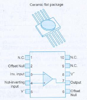
4 PACKAGES OF OPAMP There are three popular packages available: The metal can (TO) package The dual-in-line package (DIP) The flat package of flat pack Op-amp packages may contain single, two (dual) or four (quad) op-amps. Typical packages have 8 terminals (the can and the DIP or MINI DIP), 10 terminals (flatpacks and some cans) and 14 terminals (the DIP and the flat pack).
5 PACKAGES OF OPAMP The widely used very popular type, for example µa741 is a single op-amp and is available as an 8-pin can, an 8-pin DIP, a 10- pin flatpack or a 14-pin DIP. The µa741 is a dual 741 and comes in either a 10-pin can or a 14-pin DIP. Figure shows the various IC packages along with the top view of connection diagram.

6 PACKAGES OF OPAMP Metal can package (µa741) The metal can has eight pins with pin number 8 identified by a tab. The other pins are numbered counterclockwise from pin 8, beginning with pin 1. Pin 2 is called the inverting input terminal Pin 3 is the non-inverting input terminal Pin 6 is the output terminal Pins 7 and 4 are the power supply terminals labeled as V+ and V- respectively. Terminals 1 and 5 are used for dc offset. The pin 8 marked NC indicates 'No Connection'.

7 PACKAGES OF OPAMP DIP package of 741 The top pin on the left of the notch locates pin 1, and the flat pack of has a dot on it for identification. The other pins are numbered counter-clockwise from pin 1. The pin numbers have been illustrated only for some popular op-amps and the user should consult the manufacturer's data sheet before connecting a given op-amp into a circuit.

8 PACKAGES OF OPAMP
9 Power Supply Connections The V+ and V- power supply terminals are connected to two dc voltage sources. The V+ pin is connected to the positive terminal of one source and the V- pin is connected to the negative terminal of the other source as illustrated in figure (a) where the two sources are 15 V batteries each. These are typical values, but in general, the power supply voltage may range from about: ±5 V to ±22 V. The common terminal of the V+ and V- sources is connected to a reference point or ground.

10 Power Supply Connections
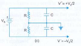
11 Power Supply Connections Some op-amps have a ground terminal, but most do not. The ground is simply a convenient point on the circuit bread-board to which the op-amp is connected through the power supplies. The equivalent representation of fig. (a) is given in fig. (b). The common point of the two supplies must be grounded, otherwise twice the supply voltage will get applied and it may damage the op-amp. Instead of using two power supplies, one can use a single power supply to obtain V+ and V- as shown in circuits of fig. (c, d, e).

12 Power Supply Connections
13 Power Supply Connections In fig. (c), resistor R should be greater than 10 kω so that it does not draw more current from the supply Vs. The two capacitors provide decoupling of the power supply and range in value from 0.01 to 10µF. In the circuit of fig. (d), zener diodes are used to give symmetrical supply voltages. The value of the resistor Rs is chosen such that it supplies sufficient current for the zener diodes to operate in the avalanche mode.
14 Power Supply Connections In fig. (e), potentiometer is used to get equal values of V+ and V-. Diodes D 1 and D 2 protect the IC if the positive and negative leads of the supply voltage Vs are accidentally reversed. These diodes can also be connected in the circuits of fig. (c) and (d).
15 Manufacturer's Designation Each manufacturer uses a specific code and assigns a specific type number to the ICs produced. For example, 741 an internally compensated opamp originally manufactured by Fairchild is sold as µa741. Here µa represents the identifying initials used by Fairchild.
16 Manufacturer's Designation The codes used by some of the well-known manufacturers of linear ICs are: Fairchild - µa, µaf National Semiconductor - LM, LH, LF, TBA Motorola - MC, MFC RCA - CA, CD Texas Instruments - SN Signetics - N/S, NE/SE Burr-Brown - BB
17 Manufacturer's Designation A number of manufacturers also produce popular ICs of the other manufacturers. For easy use, they usually retain the original type number of the IC along with their identifying initials. For example, Fairchild's original µa741 is also manufactured by other manufacturers as follows: National Semiconductor - LM741 Motorola - MC1741 RCA - CA3741 Texas Instruments - SN52741 Signetics - N5741
18 Manufacturer's Designation It may be noted that the last three digits in each manufacturer's designation are 741. All these op-amps have the same specifications. Since a number of manufacturers produce the same IC, one can refer to such ICs by their type number only and delete manufacturer's identifying initials. For example, µ741 or MC1741 may simple be referred as 741. Some linear ICs are available in different classes such as A, C, E, Sand SC.
19 Manufacturer's Designation For example 741, 741 A, 741C, 741 E, 741 Sand 741 SC are different versions of the same op-amp. The main difference of these op-amps are: 741 :Military grade op-amp (Operating temperature range -55 to 125 C) 741C :Commercial grade op-amp (Operating temperate range 0 to 700/75 C) 741A :Improved version of 741 Better electrical specifications 741E :Improved version of 741 C - Better electrical specifications 741S :Military grade op-amp with higher slew-rate 741SC :Commercial grade op-amp with higher slewrate

20 Ideal Operational Amplifier The schematic symbol of an op-amp is shown in fig. (a). It has two input terminals and one output terminal. Other terminals have not been shown for simplicity. The - and + symbols at the input refer to inverting and non-inverting input terminals respectively.
21 Ideal Operational Amplifier If V 1 = 0, output V o is 180 out of phase with input signal V 2. When V 2 = 0, output V o will be in phase with the input signal applied at V 1. This op-amp is said to be ideal if it has the following characteristics. Open loop voltage gain : A OL = Input impedance : R i = Output impedance :R o = 0 Bandwidth : BW = Zero offset : V o when V 1 = V 2 = 0
22 Ideal Operational Amplifier An ideal op-amp draws no current at both the input terminals i.e., i 1 =i 2 =0. Because of infinite input impedance, any signal source can drive it and there is no loading on the preceding driver stage. Since gain is, the voltage between the inverting and non-inverting terminals, i.e., differential input voltage V d =(V 1 V 2 ) is essentially zero for finite output voltage V o. The output voltage V o is independent of the current drawn from the output as R o = 0. The output thus can drive an infinite number of other devices.
23 Ideal Operational Amplifier An ideal op-amp draws no current at both the input terminals i.e., i 1 =i 2 =0. Because of infinite input impedance, any signal source can drive it and there is no loading on the preceding driver stage. Since gain is, the voltage between the inverting and non-inverting terminals, i.e., differential input voltage V d =(V 1 V 2 )is essentially zero for finite output voltage V o. The output voltage V o is independent of the current drawn from the output as R o = 0.

24 Ideal Operational Amplifier The output thus can drive an infinite number of other devices. A physical amplifier is not an ideal one. So, the equivalent circuit of an op-amp may be shown in fig. (b) where A OL, Ri and R O = 0.
25 Ideal Operational Amplifier It can be seen that op-amp is a voltage controlled voltage source and A OL V d is an equivalent Thevenin voltage source and R o is the Thevenin equivalent resistance looking back into the output terminal of an op-amp. The equivalent circuit is useful in analyzing the basic operating principles of op-amp. For the circuit shown in fig. (b), V O is The equation shows that the op-amp amplifies the difference between the two input voltages.
 where signals V 1 and V 2 are applied at non-inverting and inverting input terminals respectively.")
26 Open Loop Operation - OpAmp The simplest way to use an op-amp is in the open loop mode. Refer to fig. (c) where signals V 1 and V 2 are applied at non-inverting and inverting input terminals respectively.
27 Feedback in Ideal Op-Amp The utility of an op-amp can be greatly increased by providing negative feedback. The output in this case is not driven into saturation and the circuit behaves in a linear manner. There are two basic feedback connections used. In order to understand the operation of these circuits, we make two realistic simplifying assumptions discussed earlier also. The current drawn by either of the input terminals (non-inverting and inverting) is negligible. The differential input voltage Vd between noninverting and inverting input terminals is essentially zero.

28 Inverting Amplifier This is perhaps the most widely used of all the opamp circuits. The output voltage Vo is fed back to the inverting input terminal through the R f R 1 network where R f is the feedback resistor. Input signal V i (ac or dc) is applied to the inverting input terminal through R 1 and non-inverting input terminal of op-amp is grounded.
29 Inverting Amplifier - Analysis For simplicity, assume an ideal op-amp. As V d =0, node 'a' is at ground potential and the current i 1 through R 1 is Also since op-amp draws no current, all the current flowing through R 1 must flow through R f. The output voltage, Hence, the gain of the inverting amplifier (also referred as closed loop gain) is,
30 Inverting Amplifier - Analysis Alternatively, the nodal equation at the node 'a' in fig. is where va is the voltage at node 'a'. Since node 'a' is at virtual ground va = O. Therefore, we get, The negative sign indicates a phase shift of 180 between V i and V o. Also since inverting input terminal is at virtual ground, the effective input impedance is R 1
31 Inverting Amplifier - Analysis The value of R 1 should be kept fairly large to avoid loading effect. This however, limits the gain that can be obtained from this circuit. A load resistor RL is usually put at the output in actual practice otherwise, the input impedance of the measuring device such as oscilloscope or DVM acts as the load. If, however, resistances R 1 and R f in Fig. 2.5 (a) are replaced by impedances Z 1 and Z f respectively, then the voltage gain, A CL will be This expression for the voltage gain will be used in op-amp application, such as integrator, differentiator etc.
32 Practical Inverting Amplifier For a practical op-amp, the expression for the closed loop voltage gain should be calculated using the low frequency model. The equivalent circuit of a practical inverting amplifier is shown in fig. (a)
33 Practical Inverting Amplifier This circuit can be simplified by replacing the signal source V i and resistors R 1 and R i by Thevenin's equivalent as shown in fig. (b) which is analyzed to calculate the exact expression for closed loop gain, ACL and input impedance R if.
34 Practical Inverting Amplifier The input impedance Ri of an op-amp is usually much greater than R 1, so one may assume, V eq =V i and R eq =R 1.From the output loop in fig. (b) Putting the value of V d and simplifying, Also the KVL loop equation gives
35 Practical Inverting Amplifier Putting the value of i from and solving for closed loop gain A CL = V o /V i if A OL»1 and A OL R 1» R o + R f, and neglecting R o, Input Resistance R f Writing the loop equation and solving for R if,
36 Practical Inverting Amplifier Output Resistance R of Output impedance R of (without load resistance R L is calculated from the open circuit output voltage v oc and short circuit output circuit i sc. Now consider the circuit shown in Fig. (c).
37 Practical Inverting Amplifier Under short circuit conditions at output,

38 Practical Inverting Amplifier Putting the value of A CL It may be seen that numerator consists of a term R o (R 1 +R f ) and is therefore smaller than R o. The output resistance R of (with feedback) is therefore always less than R o and for A CL, R of 0.
39 Non Inverting Amplifier If a signal (ac or dc) is applied to the non-inverting input terminal and feedback is given as shown in fig. (a), the circuit amplifies without inverting the input signal. Such a circuit is called non-inverting amplifier.
40 Non Inverting Amplifier It may be noted that it is also a negative feed-back system as output is being fed back to the inverting input terminal. As the differential voltage V d at the input terminal of op-amp is zero, the voltage at node 'a' in fig. (a) is V i same as the input voltage applied to noninverting input terminal. Now R f and R 1 forms a potential divider. Hence as no current flows into the op-amp.
41 Non Inverting Amplifier Thus, for non-inverting amplifier the voltage gain, The gain can be adjusted to unity or more, by proper selection of resistors R f and R 1. Compared to the inverting amplifier, the input resistance of the non-inverting amplifier is extremely large (= ) as the op-amp draws negligible current from the signal source.

42 Non Inverting Amplifier The analysis of a practical non-inverting amplifier can be performed by using the equivalent circuit shown in fig. (b).

43 Non Inverting Amplifier Writing KCL at the output node,
44 Voltage Follower In the non-inverting amplifier of fig. if R f =0 and R 1 =, we get the modified circuit.
45 Differential Amplifier A circuit that amplifies the difference between two signals is called a difference or differential amplifier. This type of the amplifier is very useful in instrumentation circuits A typical circuit is shown in fig.
46 Differential Amplifier Since, the differential voltage at the input terminals of the op-amp is zero, nodes 'a' and 'b' are at the same potential, designated as V 3. The nodal equation at 'a' is, The nodal equation at b' is,
47 Differential Amplifier Difference-mode and Common-mode Gains if V 1 =V 2 then V o = 0. That is, the signal common to both inputs gets cancelled and produces no output voltage. This is true for an ideal op-amp, however, a practical op-amp exhibits some small response to the common mode component of the input voltages too. The output voltage depends not only upon the difference signal V d at the input, but is also affected by the average voltage of the input signals, called the common-mode signal V CM.
48 Differential Amplifier Difference-mode and Common-mode Gains The common-mode signal V CM. defined as, For differential amplifier, though the circuit is symmetric, but because of the mismatch, the gain at the output with respect to the positive terminal is slightly different in magnitude to that of the negative terminal. So, even with the same voltage applied to both inputs, the output is not zero. The output, therefore, must be expressed as,
49 Differential Amplifier Difference-mode and Common-mode Gains The output, therefore, must be expressed as, where, A 1 (A 2 ) is the voltage amplification from input 1 (2) to the output with input 2(1) grounded.
50 Differential Amplifier Common-Mode Rejection Ratio The relative sensitivity of an op-amp to a difference signal as compared to a common-mode signal is called common-mode rejection ratio (CMRR) and gives the figure of merit ρ for the differential amplifier. So, CMRR is given by: It is usually expressed in decibels (db). For example, the µa741 op-amp has a minimum CMRR of 70 db whereas a precision op-amp such as µa725a has a minimum CMRR of 120 db.
51 Conclusion In this presentation, we learnt about Basic configuration of op-amp. Packages of op-amp. Power supply connections of op-amp. Nomenclature of op-amp. Characteristics of ideal operational amplifier. Characteristics of practical operational amplifier.
UNIT I. Operational Amplifiers
 UNIT I Operational Amplifiers Operational Amplifier: The operational amplifier is a direct-coupled high gain amplifier. It is a versatile multi-terminal device that can be used to amplify dc as well as
Operational amplifiers
 Operational amplifiers Bởi: Sy Hien Dinh INTRODUCTION Having learned the basic laws and theorems for circuit analysis, we are now ready to study an active circuit element of paramount importance: the operational
ES250: Electrical Science. HW6: The Operational Amplifier
 ES250: Electrical Science HW6: The Operational Amplifier Introduction This chapter introduces the operational amplifier or op amp We will learn how to analyze and design circuits that contain op amps,
Chapter 10: The Operational Amplifiers
 Chapter 10: The Operational Amplifiers Electronic Devices Operational Amplifiers (op-amp) Op-amp is an electronic device that amplify the difference of voltage at its two inputs. It has two input terminals,
EE LINEAR INTEGRATED CIRCUITS & APPLICATIONS
 UNITII CHARACTERISTICS OF OPAMP 1. What is an opamp? List its functions. The opamp is a multi terminal device, which internally is quite complex. It is a direct coupled high gain amplifier consisting of
Analog Electronics. Lecture Pearson Education. Upper Saddle River, NJ, All rights reserved.
 Analog Electronics V Lecture 5 V Operational Amplifers Op-amp is an electronic device that amplify the difference of voltage at its two inputs. V V 8 1 DIP 8 1 DIP 20 SMT 1 8 1 SMT Operational Amplifers
Operational Amplifiers
 Fundamentals of op-amp Operation modes Golden rules of op-amp Op-amp circuits Inverting & non-inverting amplifier Unity follower, integrator & differentiator Introduction An operational amplifier, or op-amp,
Lesson number one. Operational Amplifier Basics
 What About Lesson number one Operational Amplifier Basics As well as resistors and capacitors, Operational Amplifiers, or Op-amps as they are more commonly called, are one of the basic building blocks
Homework Assignment 03
 Homework Assignment 03 Question 1 (Short Takes), 2 points each unless otherwise noted. 1. Two 0.68 μf capacitors are connected in series across a 10 khz sine wave signal source. The total capacitive reactance
L02 Operational Amplifiers Applications 1
 L02 Operational Amplifiers Applications 1 Chapter 9 Ideal Operational Amplifiers and Op-Amp Circuits Donald A. Neamen (2009). Microelectronics: Circuit Analysis and Design, 4th Edition, Mc-Graw-Hill Prepared
Chapter 3: Operational Amplifiers
 Chapter 3: Operational Amplifiers 1 OPERATIONAL AMPLIFIERS Having learned the basic laws and theorems for circuit analysis, we are now ready to study an active circuit element of paramount importance:
Università degli Studi di Roma Tor Vergata Dipartimento di Ingegneria Elettronica. Analogue Electronics. Paolo Colantonio A.A.
 Università degli Studi di Roma Tor Vergata Dipartimento di Ingegneria Elettronica Analogue Electronics Paolo Colantonio A.A. 2056 Operational amplifiers (op amps) Operational amplifiers (op amps) are among
LM148/LM248/LM348 Quad 741 Op Amps
 Quad 741 Op Amps General Description The LM148 series is a true quad 741. It consists of four independent, high gain, internally compensated, low power operational amplifiers which have been designed to
Gechstudentszone.wordpress.com
 8.1 Operational Amplifier (Op-Amp) UNIT 8: Operational Amplifier An operational amplifier ("op-amp") is a DC-coupled high-gain electronic voltage amplifier with a differential input and, usually, a single-ended
Operational Amplifiers (Op Amps)
") Operational Amplifiers (Op Amps) Introduction * An operational amplifier is modeled as a voltage controlled voltage source. * An operational amplifier has a very high input impedance and a very high gain.
Operational Amplifiers (Op Amps) Introduction * An operational amplifier is modeled as a voltage controlled voltage source. * An operational amplifier has a very high input impedance and a very high gain.
Analog Electronic Circuits Code: EE-305-F
 Analog Electronic Circuits Code: EE-305-F 1 INTRODUCTION Usually Called Op Amps Section -C Operational Amplifier An amplifier is a device that accepts a varying input signal and produces a similar output
Operational Amplifiers. Boylestad Chapter 10
 Operational Amplifiers Boylestad Chapter 10 DC-Offset Parameters Even when the input voltage is zero, an op-amp can have an output offset. The following can cause this offset: Input offset voltage Input
Chapter 9: Operational Amplifiers
 Chapter 9: Operational Amplifiers The Operational Amplifier (or op-amp) is the ideal, simple amplifier. It is an integrated circuit (IC). An IC contains many discrete components (resistors, capacitors,
C H A P T E R 02. Operational Amplifiers
 C H A P T E R 02 Operational Amplifiers The Op-amp Figure 2.1 Circuit symbol for the op amp. Figure 2.2 The op amp shown connected to dc power supplies. The Ideal Op-amp 1. Infinite input impedance 2.
OPERATIONAL AMPLIFIER PREPARED BY, PROF. CHIRAG H. RAVAL ASSISTANT PROFESSOR NIRMA UNIVRSITY
 OPERATIONAL AMPLIFIER PREPARED BY, PROF. CHIRAG H. RAVAL ASSISTANT PROFESSOR NIRMA UNIVRSITY INTRODUCTION Op-Amp means Operational Amplifier. Operational stands for mathematical operation like addition,
Chapter 9: Operational Amplifiers
 Chapter 9: Operational Amplifiers The Operational Amplifier (or op-amp) is the ideal, simple amplifier. It is an integrated circuit (IC). An IC contains many discrete components (resistors, capacitors,
Infrared Communications Lab
 Infrared Communications Lab This lab assignment assumes that the student knows about: Ohm s Law oltage, Current and Resistance Operational Amplifiers (See Appendix I) The first part of the lab is to develop
Operational Amplifier BME 360 Lecture Notes Ying Sun
 Operational Amplifier BME 360 Lecture Notes Ying Sun Characteristics of Op-Amp An operational amplifier (op-amp) is an analog integrated circuit that consists of several stages of transistor amplification
Integrated Circuit: Classification:
 Integrated Circuit: It is a miniature, low cost electronic circuit consisting of active and passive components that are irreparably joined together on a single crystal chip of silicon. Classification:
Lecture Notes Unit-III
 Lecture Notes Unit-III FAQs Q1: An operational amplifier has a differential gain of 103 and CMRR of 100, input voltages are 120µV and 80µV, determine output voltage. 2 MARKS
Chapter 2. Operational Amplifiers
 Chapter 2. Operational Amplifiers Tong In Oh 1 2.3 The Noninverting Configuration v I is applied directly to the positive input terminal of the op amp One terminal of is connected to ground Closed-loop
6. The Operational Amplifier
 1 6. The Operational Amplifier This chapter introduces a new component which, although technically nonlinear, can be treated effectively with linear models This element known as the operational amplifier
LDIC Course Contents. - Operational Amplifier. - Applications of OP-Amp. - D-A and A-D Converters. - Logic Families
 LDIC Course Contents Unit 1 - Operational Amplifier Unit 2 - Applications of OP-Amp Unit 3 - Oscillators Unit 4 - D-A and A-D Converters Unit 5 - Logic Families Unit 6 - Memories Text Books: 1. Linear
About the Tutorial. Audience. Prerequisites. Copyright & Disclaimer. Linear Integrated Circuits Applications
 About the Tutorial Linear Integrated Circuits are solid state analog devices that can operate over a continuous range of input signals. Theoretically, they are characterized by an infinite number of operating
 Distributed by: www.jameco.com 1-800-831-4242 The content and copyrights of the attached material are the property of its owner. LM148/LM248/LM348 Quad 741 Op Amps General Description The LM148 series
Homework Assignment True or false. For both the inverting and noninverting op-amp configurations, V OS results in
 Question 1 (Short Takes), 2 points each. Homework Assignment 02 1. An op-amp has input bias current I B = 1 μa. Make an estimate for the input offset current I OS. Answer. I OS is normally an order of
Operational Amplifiers
 Basic Electronics Syllabus: Introduction to : Ideal OPAMP, Inverting and Non Inverting OPAMP circuits, OPAMP applications: voltage follower, addition, subtraction, integration, differentiation; Numerical
Type Ordering Code Package TAE 4453 G Q67000-A2152 P-DSO-14-1 (SMD) TAF 4453 G Q67000-A2213 P-DSO-14-1 (SMD)
 TAF 4453 G Q67000-A2213 P-DSO-14-1 (SMD)") Quad PNP-Operational Amplifier TAE 4453 Bipolar IC Features Supply voltage range between 3 and 36 Low current consumption, 1.6 ma typ. Extremely large control range Low output saturation voltage, almost
Quad PNP-Operational Amplifier TAE 4453 Bipolar IC Features Supply voltage range between 3 and 36 Low current consumption, 1.6 ma typ. Extremely large control range Low output saturation voltage, almost
Linear IC s and applications
 Questions and Solutions PART-A Unit-1 INTRODUCTION TO OP-AMPS 1. Explain data acquisition system Jan13 DATA ACQUISITION SYSYTEM BLOCK DIAGRAM: Input stage Intermediate stage Level shifting stage Output
EE 3305 Lab I Revised July 18, 2003
 Operational Amplifiers Operational amplifiers are high-gain amplifiers with a similar general description typified by the most famous example, the LM741. The LM741 is used for many amplifier varieties
Operational Amplifier: Characteristics and Open-Loop Op-Amp
 Lesson: Operational Amplifier: Characteristics and Open- Loop Op- Amp Lesson Developer: Dr. Arun Vir Singh College/Department: Shivaji College, University of Delhi Institute of Lifelong Learning, Delhi
ECE:3410 Electronic Circuits
 ECE:3410 Electronic Circuits Reiew of Op-Amps Sections of Chapters 9 & 14 A. Kruger Op-Amp Reiew-1 Real-World Op-Amp In earlier courses, op-amp were often considered ideal Infinite input resistance Infinite
Introduction to Op Amps By Russell Anderson, Burr-Brown Corp
 Introduction to Op Amps By ussell Anderson, BurrBrown Corp Introduction Analog design can be intimidating. If your engineering talents have been focused in digital, software or even scientific fields,
Operational Amplifiers
 Operational Amplifiers Spring 2008 Sean Lynch Lambros Samouris Tom Groshans History of Op Amps Non Named for their originally intended functions: performing mathematical operations and amplification Addition
Summer 2015 Examination
 Summer 2015 Examination Subject Code: 17445 Model Answer Important Instructions to examiners: 1) The answers should be examined by key words and not as word-to-word as given in the model answer scheme.
55:041 Electronic Circuits
 55:041 Electronic Circuits Reiew of Op-Amps Sections of Chapters 9 & 14 A. Kruger Op-Amp Reiew-1 Real-World Op-Amp In earlier courses, op-amp were often considered ideal Infinite input resistance Infinite
Applied Electronics II
 Applied Electronics II Chapter 3: Operational Amplifier Part 1- Op Amp Basics School of Electrical and Computer Engineering Addis Ababa Institute of Technology Addis Ababa University Daniel D./Getachew
An electronic unit that behaves like a voltagecontrolled
 1 An electronic unit that behaves like a voltagecontrolled voltage source. An active circuit element that amplifies, sums, subtracts, multiply, divide, differentiate or integrates a signal 2 A typical
Chapter 10: Operational Amplifiers
 Chapter 10: Operational Amplifiers Differential Amplifier Differential amplifier has two identical transistors with two inputs and two outputs. 2 Differential Amplifier Differential amplifier has two identical
Homework Assignment 01
 Homework Assignment 01 In this homework set students review some basic circuit analysis techniques, as well as review how to analyze ideal op-amp circuits. Numerical answers must be supplied using engineering
Lecture #2 Operational Amplifiers
 Spring 2015 Benha University Faculty of Engineering at Shoubra ECE-322 Electronic Circuits (B) Lecture #2 Operational Amplifiers Instructor: Dr. Ahmad El-Banna Agenda Introduction Op-Amps Input Modes and
Introduction to Operational Amplifiers
 P. R. Nelson ECE 322 Fall 2012 p. 1/50 Introduction to Operational Amplifiers Phyllis R. Nelson prnelson@csupomona.edu Professor, Department of Electrical and Computer Engineering California State Polytechnic
Electronics - PHYS 2371/2 TODAY
 TODAY 4-terminal linear amplifier Op-Amp Basics, Ch-28, 31 Op-Amp Golden Rules for operation Op-amp gain, impedance, frequency response Videos Lab-6 Overview 1 Review Semiconductors Semiconductors Resistivity
Department of Mechanical Engineering
 Department of Mechanical Engineering 2.010 CONTROL SYSTEMS PRINCIPLES Introduction to the Operational Amplifier The integrated-circuit operational-amplifier is the fundamental building block for many electronic
Unit WorkBook 1 Level 4 ENG U22 Electronic Circuits and Devices 2018 UniCourse Ltd. All Rights Reserved. Sample
 Pearson BTEC Level 4 Higher Nationals in Engineering (RQF) Unit 22: Electronic Circuits and Devices Unit Workbook 1 in a series of 4 for this unit Learning Outcome 1 Operational Amplifiers Page 1 of 23
Başkent University Department of Electrical and Electronics Engineering EEM 311 Electronics II Experiment 8 OPERATIONAL AMPLIFIERS
 Başkent University Department of Electrical and Electronics Engineering EEM 311 Electronics II Experiment 8 Objectives: OPERATIONAL AMPLIFIERS 1.To demonstrate an inverting operational amplifier circuit.
Laboratory 9. Required Components: Objectives. Optional Components: Operational Amplifier Circuits (modified from lab text by Alciatore)
") Laboratory 9 Operational Amplifier Circuits (modified from lab text by Alciatore) Required Components: 1x 741 op-amp 2x 1k resistors 4x 10k resistors 1x l00k resistor 1x 0.1F capacitor Optional Components:
Laboratory 9 Operational Amplifier Circuits (modified from lab text by Alciatore) Required Components: 1x 741 op-amp 2x 1k resistors 4x 10k resistors 1x l00k resistor 1x 0.1F capacitor Optional Components:
TL082 Wide Bandwidth Dual JFET Input Operational Amplifier
 TL082 Wide Bandwidth Dual JFET Input Operational Amplifier General Description These devices are low cost, high speed, dual JFET input operational amplifiers with an internally trimmed input offset voltage
MC1458, MC1558 DUAL GENERAL-PURPOSE OPERATIONAL AMPLIFIERS
 Short-Circuit Protection Wide Common-Mode and Differential oltage Ranges No Frequency Compensation Required Low Power Consumption No Latch-Up Designed to Be Interchangeable With Motorola MC1/MC1 and Signetics
IFB270 Advanced Electronic Circuits
 IFB270 Advanced Electronic Circuits Chapter 12: The operational amplifier Prof. Manar Mohaisen Department of EEC Engineering Review of the Precedent Lecture Introduce the four layer diode Introduce the
LF353 Wide Bandwidth Dual JFET Input Operational Amplifier
 LF353 Wide Bandwidth Dual JFET Input Operational Amplifier General Description These devices are low cost, high speed, dual JFET input operational amplifiers with an internally trimmed input offset voltage
ELECTRONICS. EE 42/100 Lecture 8: Op-Amps. Rev B 3/3/2010 (9:13 PM) Prof. Ali M. Niknejad
 Prof. Ali M. Niknejad") A. M. Niknejad University of California, Berkeley EE 100 / 42 Lecture 8 p. 1/21 EE 42/100 Lecture 8: Op-Amps ELECTRONICS Rev B 3/3/2010 (9:13 PM) Prof. Ali M. Niknejad University of California, Berkeley
A. M. Niknejad University of California, Berkeley EE 100 / 42 Lecture 8 p. 1/21 EE 42/100 Lecture 8: Op-Amps ELECTRONICS Rev B 3/3/2010 (9:13 PM) Prof. Ali M. Niknejad University of California, Berkeley
ELECTRONICS. EE 42/100 Lecture 8: Op-Amps. Rev A 2/10/2010 (6:47 PM) Prof. Ali M. Niknejad
 Prof. Ali M. Niknejad") A. M. Niknejad University of California, Berkeley EE 100 / 42 Lecture 8 p. 1/21 EE 42/100 Lecture 8: Op-Amps ELECTRONICS Rev A 2/10/2010 (6:47 PM) Prof. Ali M. Niknejad University of California, Berkeley
A. M. Niknejad University of California, Berkeley EE 100 / 42 Lecture 8 p. 1/21 EE 42/100 Lecture 8: Op-Amps ELECTRONICS Rev A 2/10/2010 (6:47 PM) Prof. Ali M. Niknejad University of California, Berkeley
Introduction to Op Amps
 Introduction to Op Amps ENGI 242 ELEC 222 Basic Op-Amp The op-amp is a differential amplifier with a very high open loop gain 25k AVOL 500k (much higher for FET inputs) high input impedance 500kΩ ZIN 10MΩ
Operational Amplifiers
 Operational Amplifiers From: http://ume.gatech.edu/mechatroni cs_course/opamp_f11.ppt What is an Op-Amp? The Surface An Operational Amplifier (Op-Amp) is an integrated circuit that uses external voltage
Concepts to be Reviewed
 Introductory Medical Device Prototyping Analog Circuits Part 3 Operational Amplifiers, http://saliterman.umn.edu/ Department of Biomedical Engineering, University of Minnesota Concepts to be Reviewed Operational
Lecture 2 - A Analog Signal Conditioning
 Lecture 2 - A Analog Signal Conditioning EE 521: Instrumentation and Measurements Lecture Notes Update on September 10, 2009 Aly El-Osery, Electrical Engineering Dept., New Mexico Tech 2 - A.1 Contents
Homework Assignment 07
 Homework Assignment 07 Question 1 (Short Takes). 2 points each unless otherwise noted. 1. A single-pole op-amp has an open-loop low-frequency gain of A = 10 5 and an open loop, 3-dB frequency of 4 Hz.
LF444 Quad Low Power JFET Input Operational Amplifier
 LF444 Quad Low Power JFET Input Operational Amplifier General Description The LF444 quad low power operational amplifier provides many of the same AC characteristics as the industry standard LM148 while
Dimensions in inches (mm) .268 (6.81).255 (6.48) .390 (9.91).379 (9.63) .045 (1.14).030 (.76) 4 Typ. Figure 1. Typical application circuit.
 .268 (6.81).255 (6.48) .390 (9.91).379 (9.63) .045 (1.14).030 (.76) 4 Typ. Figure 1. Typical application circuit.") LINEAR OPTOCOUPLER FEATURES Couples AC and DC signals.% Servo Linearity Wide Bandwidth, > KHz High Gain Stability, ±.%/C Low Input-Output Capacitance Low Power Consumption, < mw Isolation Test Voltage,
LINEAR OPTOCOUPLER FEATURES Couples AC and DC signals.% Servo Linearity Wide Bandwidth, > KHz High Gain Stability, ±.%/C Low Input-Output Capacitance Low Power Consumption, < mw Isolation Test Voltage,
LM348. Quad Operational Amplifier. Features. Description. Internal Block Diagram.
 Quad Operational Amplifier www.fairchildsemi.com Features LM741 OP Amp operating characteristics Low supply current drain Class AB output stage-no crossover distortion Pin compatible with the LM324 Low
Physics 303 Fall Module 4: The Operational Amplifier
 Module 4: The Operational Amplifier Operational Amplifiers: General Introduction In the laboratory, analog signals (that is to say continuously variable, not discrete signals) often require amplification.
EE 210 Lab Exercise #5: OP-AMPS I
 EE 210 Lab Exercise #5: OP-AMPS I ITEMS REQUIRED EE210 crate, DMM, EE210 parts kit, T-connector, 50Ω terminator, Breadboard Lab report due at the ASSIGNMENT beginning of the next lab period Data and results
Chapter 2. Operational Amplifiers
 Chapter 2. Operational Amplifiers Tong In Oh 1 Objective Terminal characteristics of the ideal op amp How to analyze op amp circuits How to use op amps to design amplifiers How to design more sophisticated
ECE-342 Test 1: Sep 27, :00-8:00, Closed Book. Name : SOLUTION
 ECE-342 Test 1: Sep 27, 2011 6:00-8:00, Closed Book Name : SOLUTION All solutions must provide units as appropriate. Use the physical constants and data as provided on the formula sheet the last page of
TL082 Wide Bandwidth Dual JFET Input Operational Amplifier
 TL082 Wide Bandwidth Dual JFET Input Operational Amplifier General Description These devices are low cost, high speed, dual JFET input operational amplifiers with an internally trimmed input offset voltage
Homework Assignment 03 Solution
 Homework Assignment 03 Solution Question 1 Determine the h 11 and h 21 parameters for the circuit. Be sure to supply the units and proper sign for each parameter. (8 points) Solution Setting v 2 = 0 h
Improving Amplifier Voltage Gain
 15.1 Multistage ac-coupled Amplifiers 1077 TABLE 15.3 Three-Stage Amplifier Summary HAND ANALYSIS SPICE RESULTS Voltage gain 998 1010 Input signal range 92.7 V Input resistance 1 M 1M Output resistance
LF411 Low Offset, Low Drift JFET Input Operational Amplifier
 Low Offset, Low Drift JFET Input Operational Amplifier General Description These devices are low cost, high speed, JFET input operational amplifiers with very low input offset voltage and guaranteed input
ELC224 Final Review (12/10/2009) Name:
 Name:") ELC224 Final Review (12/10/2009) Name: Select the correct answer to the problems 1 through 20. 1. A common-emitter amplifier that uses direct coupling is an example of a dc amplifier. 2. The frequency
ELC224 Final Review (12/10/2009) Name: Select the correct answer to the problems 1 through 20. 1. A common-emitter amplifier that uses direct coupling is an example of a dc amplifier. 2. The frequency
Lecture 01 Operational Amplifiers Op-Amps Introduction
 Lecture 01 Operational Amplifiers Op-Amps Introduction Chapter 9 Ideal Operational Amplifiers and Op-Amp Circuits Donald A. Neamen (2009). Microelectronics: Circuit Analysis and Design, 4th Edition, Mc-Graw-Hill
MC1458, MC1558 DUAL GENERAL-PURPOSE OPERATIONAL AMPLIFIERS
 Short-Circuit Protection Wide Common-Mode and Differential oltage Ranges No Frequency Compensation Required Low Power Consumption No Latch-Up Designed to Be Interchangeable With Motorola MC/MC and Signetics
LF442 Dual Low Power JFET Input Operational Amplifier
 LF442 Dual Low Power JFET Input Operational Amplifier General Description The LF442 dual low power operational amplifiers provide many of the same AC characteristics as the industry standard LM1458 while
IC Preamplifier Challenges Choppers on Drift
 IC Preamplifier Challenges Choppers on Drift Since the introduction of monolithic IC amplifiers there has been a continual improvement in DC accuracy. Bias currents have been decreased by 5 orders of magnitude
LM146/LM346 Programmable Quad Operational Amplifiers
 LM146/LM346 Programmable Quad Operational Amplifiers General Description The LM146 series of quad op amps consists of four independent, high gain, internally compensated, low power, programmable amplifiers.
Emitter Coupled Differential Amplifier
 Emitter Coupled Differential Amplifier Returning to the transistor, a very common and useful circuit is the differential amplifier. It's basic circuit is: Vcc Q1 Q2 Re Vee To see how this circuit works,
EECE251 Circuit Analysis I Set 5: Operational Amplifiers
 EECE251 Circuit Analysis I Set 5: Operational Amplifiers Shahriar Mirabbasi Department of Electrical and Computer Engineering University of British Columbia shahriar@ece.ubc.ca 1 Amplifiers There are various
ELEC207 LINEAR INTEGRATED CIRCUITS
 Concept of VIRTUAL SHORT For feedback amplifiers constructed with op-amps, the two op-amp terminals will always be approximately equal (V + = V - ) This condition in op-amp feedback amplifiers is known
Chapter 2. Operational Amplifiers
 Chapter 2. Operational Amplifiers Tong In Oh 1 2.5 Integrators and Differentiators Utilized resistors in the op-amp feedback and feed-in path Ideally independent of frequency Use of capacitors together
LINEAR IC APPLICATIONS
 1 B.Tech III Year I Semester (R09) Regular & Supplementary Examinations December/January 2013/14 1 (a) Why is R e in an emitter-coupled differential amplifier replaced by a constant current source? (b)
Chapter 5. Operational Amplifiers and Source Followers. 5.1 Operational Amplifier
 Chapter 5 Operational Amplifiers and Source Followers 5.1 Operational Amplifier In single ended operation the output is measured with respect to a fixed potential, usually ground, whereas in double-ended
55:041 Electronic Circuits The University of Iowa Fall Exam 3. Question 1 Unless stated otherwise, each question below is 1 point.
 Exam 3 Name: Score /65 Question 1 Unless stated otherwise, each question below is 1 point. 1. An engineer designs a class-ab amplifier to deliver 2 W (sinusoidal) signal power to an resistive load. Ignoring
Combination Notch and Bandpass Filter
 Combination Notch and Bandpass Filter Clever filter design for graphic equalizer can perform both notch and bandpass functions Gain or attenuation is controlled by a potentiometer for specific frequency
What is an Op-Amp? The Surface
 What is an Op-Amp? The Surface An Operational Amplifier (Op-Amp) is an integrated circuit that uses external voltage to amplify the input through a very high gain. We recognize an Op-Amp as a massproduced
Laboratory 4 Operational Amplifier Department of Mechanical and Aerospace Engineering University of California, San Diego MAE170
 Laboratory 4 Operational Amplifier Department of Mechanical and Aerospace Engineering University of California, San Diego MAE170 Megan Ong Diana Wu Wong B01 Tuesday 11am April 28 st, 2015 Abstract: The
Common Reference Example
 Operational Amplifiers Overview Common reference circuit diagrams Real models of operational amplifiers Ideal models operational amplifiers Inverting amplifiers Noninverting amplifiers Summing amplifiers
An amplifier increases the power (amplitude) of an
 of an") Amplifiers Signal In Amplifier Signal Out An amplifier increases the power (amplitude) of an electronic signal, as shown in the figure above. Amplifiers are found everywhere in TV s, radios. MP3 players,
Amplifiers Signal In Amplifier Signal Out An amplifier increases the power (amplitude) of an electronic signal, as shown in the figure above. Amplifiers are found everywhere in TV s, radios. MP3 players,
HOME ASSIGNMENT. Figure.Q3
 HOME ASSIGNMENT 1. For the differential amplifier circuit shown below in figure.q1, let I=1 ma, V CC =5V, v CM = -2V, R C =3kΩ and β=100. Assume that the BJTs have v BE =0.7 V at i C =1 ma. Find the voltage
LF444 Quad Low Power JFET Input Operational Amplifier
 LF444 Quad Low Power JFET Input Operational Amplifier General Description The LF444 quad low power operational amplifier provides many of the same AC characteristics as the industry standard LM148 while
Single Supply, Rail to Rail Low Power FET-Input Op Amp AD820
 a FEATURES True Single Supply Operation Output Swings Rail-to-Rail Input Voltage Range Extends Below Ground Single Supply Capability from + V to + V Dual Supply Capability from. V to 8 V Excellent Load
Basic electronics Prof. T.S. Natarajan Department of Physics Indian Institute of Technology, Madras Lecture- 24
 Basic electronics Prof. T.S. Natarajan Department of Physics Indian Institute of Technology, Madras Lecture- 24 Mathematical operations (Summing Amplifier, The Averager, D/A Converter..) Hello everybody!
EE301 Electronics I , Fall
 EE301 Electronics I 2018-2019, Fall 1. Introduction to Microelectronics (1 Week/3 Hrs.) Introduction, Historical Background, Basic Consepts 2. Rewiev of Semiconductors (1 Week/3 Hrs.) Semiconductor materials
LF412 Low Offset, Low Drift Dual JFET Input Operational Amplifier
 LF412 Low Offset, Low Drift Dual JFET Input Operational Amplifier General Description These devices are low cost, high speed, JFET input operational amplifiers with very low input offset voltage and guaranteed
LAB 5 OPERATIONAL AMPLIFIERS
 LAB 5 OPERATIONAL AMPLIFIERS PRE-LAB CALCULATIONS: Use circuit analysis techniques learned in class to analyze the circuit in Figure 5.2. Solve for Vo assuming that the effective resistance of the LED
Unit 6 Operational Amplifiers Chapter 5 (Sedra and Smith)
") Unit 6 Operational Amplifiers Chapter 5 (Sedra and Smith) Prepared by: S V UMA, Associate Professor, Department of ECE, RNSIT, Bangalore Reference: Microelectronic Circuits Adel Sedra and K C Smith 1 Objectives
Unit 6 Operational Amplifiers Chapter 5 (Sedra and Smith) Prepared by: S V UMA, Associate Professor, Department of ECE, RNSIT, Bangalore Reference: Microelectronic Circuits Adel Sedra and K C Smith 1 Objectives