NMEA Training Overview
|
|
|
- Chad Stephens
- 6 years ago
- Views:
Transcription
 Basic NMEA 2000 Network Installer Basic Marine Electronics Installer (MEI) Advanced NMEA 2000 Network")
1 NMEA Training Overview NMEA offers 4 classroom installer training courses Basic Marine Electronics Installer (MEI) Basic NMEA 2000 Network Installer Basic Marine Electronics Installer (MEI) Advanced NMEA 2000 Network Installer
2 MEI Training Overview General Knowledge Ohms Law Grounds Batteries & Battery Charging Systems DC Wiring Coaxial Cables Antenna Installations Display Installations Black Box Installations Marine VHF Radio Installations Automatic Identification Systems AIS Installations Radar Installations Transducer Installations Heading Sensor Installations NMEA Data Interfacing EMI 8
 I(Current in Amps)= 60 / 24 Current")
3 Ohm s Law Examples A Radar is rated at 60 Watts. What is the current draw when operating at 24V? Voltage Current Power 24 Volts X Amps 60 Watts I = P / E (Current = Power / Voltage) I(Current in Amps)= 60 / 24 Current is 2.5 Amps 2015 NMEA 26
4 Drilling Solid Fiberglass with Gel Coat 18
5 VHF Radio: Post Install Checks 1. Check Transmit Power into Dummy Load prior to testing antenna 2. Confirm sufficient radio supply voltage during HI Transmit 3. Test Forward and Reflected Power (25W radio should have <= 3W reflected) 4. Check receiver by listening for local traffic and distant NOAA weather channels 5. Perform Radio Check. Do not use CH16! (Check local area for automated test services) 6. Confirm that Lat/Lon displayed. (Advise owner on obtaining MMSI #) 7. Confirm all other functions & auxiliary equipment NMEA


6 Marine Frequency Spectrum Sat TV GHz KU KA Band WiFi GHz L - S Band Irridium 1.6 GHz L Band GPS 1575 MHz UHF Band Marine VHF MHz VHF Band Vsat GHz KU KA Band FCMW Radar 9 GHz X Band Standard C 1.5 GHz L Band Cellular MHz UHF L Band AIS 162 MHz VHF Band X Band Radar 9.4 GHz X Band S Band Radar 3 GHz S Band Fleet Broadband 1-2 GHz L Band EPIRB / PLB 406 MHz UHF Band NavTex 518kHz LF Band SSB 2-30 MHz MF HF Band 76 PLB 121 MHz VHF Band


7 Coaxial Connector Selection Connector Type Maximum Frequency Impedance Common Uses UHF (PL-259) 300 MHz 50-Ohm VHF, SSB, DGPS, Stereo, AIS BNC 4.0 GHz 50-Ohm VHF, SSB, DGPS, Cell, GPS, AIS TNC 2.5 GHz 50-Ohm SSB, DGPS, Cell, GPS, MINI-M N 11.0 GHz 50-Ohm VHF, SSB, DGPS, Cell, GPS, AIS F 2.0 GHz 75-Ohm TV, GPS Mini UHF 2.5 GHz 50-Ohm Cell SMA 12.0 GHz 50-Ohm SAT Phone, Satellite Radio SMB 4.0 GHz 50-Ohm Satellite Radio FME 200 MHz 50-Ohm Satellite Radio UHF (PL-259) BNC TNC N F 65


8 DC Panel Capacity Planning Calculate existing spare capacity Load of existing equipment Feed wire gauge and length Available spare breakers or fuses If Watts are given, convert to Amps E is Voltage in volts P is Power in Watts I is Current in Amps P = I x E I = P / E E = P / I 2015 NMEA 53

9 Overview Cables & Connectors Cable Specifications Building the Network Physical Planning & Documentation Power Sources & Distribution Voltage Drop Calculations Finalizing the Network Data Messages aka Parameter Group Numbers Connecting to Other Data Sources Network Setup Troubleshooting Exam 8

10 Introduction: NMEA 2000 IS. Copyright 2015 NMEA 11
11 Cables & Connectors: Simple Network Backbone and drop line topology also known as trunk and drop line. Both ends of the backbone are terminated. Network interfaces provide power for the device transceivers, so the backbone includes a pair for power and ground. 19

12 Power Distribution: Middle Power- Battery Example Termination Resistors Not shown Copyright 2015 NMEA 78
 PWR")
 12 V to 13.84V 9.5 V to 15.")
13 Testing and Troubleshooting: -With Network Power ON Pin/Signal Measurement Nominal Value Tolerance (2) PWR + (RED) Voltage Between PWR + and Pin (3) PWR- (Ground) 12 V to 13.84V 9.5 V to V Copyright 2015 NMEA 139
14 AMEI Training Overview Marine Computer Installations Data & Ethernet Electromagnetic Interference (EMI) VHF, DSC, SSB Non-Magnetic Heading Sensors Antenna Placement / Satellite Communications AIS Radar Autopilots Exam 7
15 Mounting Considerations: Linear Rudder Reference Linear RRUs are used with outboards and I/O type systems. They mount parallel with a linear drive unit. Rudder Reference Units may not be used on some Autopilots 130


16 Radar Installation Considerations Two radars require vertical separation Located outside vertical beamwidth of any other radar Some radars have blanking sectors Consider cable length necessary 118

17 AIS Equipment Location Operation from Normal Watch standing Location Pilot Plug NMEA 0183-HS Interface Pin Signal 1 Transmit A 4 Transmit B 5 Receive A 6 Receive B 9 Shield 103
18 Typical Satellite System Above Deck Below Deck Interface is dependent on Satellite Dome & System 87
19 Non-Magnetic Heading Sensor Installation Considerations Multipath Refer to manufacturers installation instructions Give considerations to equipment locations for serviceability, proper operation & functionality 76
20 Basic SSB Components 50 Ohm Coaxial Cable Connections 2dB Loss at 2-30 MHz 52
21 Avoiding EMI Problems Layout & Space Planning Identify Potential EMI Radiation Sources Identify Potential EMI Conducted Sources Avoid Potential Hot Spots Avoid bundling RF Transmission cables with data communications cables 40
 RJ45")

")


22 Ethernet Connectors(Ez) RJ45 Type Connectors Recommend EZ Type Rated IP67 or Higher (IEC 529) Durability Use manufacturer recommended cables when possible Strain relief for all cable Connections 30
23 Advanced NMEA2000 Class Room Objectives NMEA2000 CAN Topology Review NMEA2000 CAN Signaling NMEA2000 Network Characteristics NMEA2000 Device Configuration NMEA2000 Diagnostic Tools NMEA2000 Network Design
24 NMEA2000 Network Bridge Example Installed as a Drop Between Networks
25 NMEA2000 Parameter Groups Mandatory PGN s for devices Certified on or after Aug 2016 ALL Devices Must Support a Minimum Group of messages Message Name / Functionality PGN TX RX Address Claim ISO X X Product Information NMEA X Configuration Information NMEA X Request/ Group Function NMEA X Command Group Function NMEA X Acknowledgment Group Function NMEA X Acknowledgment ISO X Request ISO X TX/RX PGN List Group Function NMEA X Heartbeat PGN NMEA X Commanded Address ISO X Transport Protocol, Data Transfer ISO X Transport Protocol ISO X X


26 NMEA2000 Diagnostic Tools N2K Meter by MARETRON 6 Separate CAN Voltage Measurements For Quick Troubleshooting


27 NMEA2000 Good CAN Signaling Scope Example Note: NET-H (Yellow Trace) Dominant State Positive

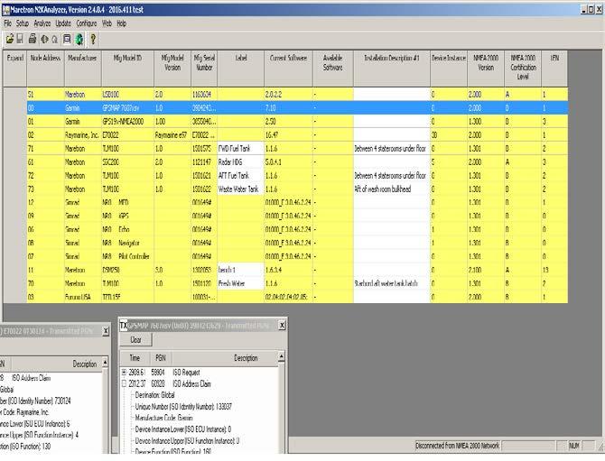
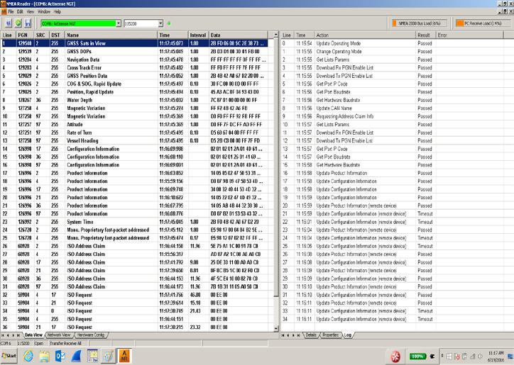
28 Advanced NMEA2000 Hands On Objectives Confirm Network Devices & Data
Thank you for buying this AIS antenna splitter.
 Thank you for buying this AIS antenna splitter. This product has been engineered to offer you the highest level of performance and durability and we hope that it will provide many years of reliable service.
Watcheye S AIS Splitter. manual
 Watcheye S AIS Splitter manual Thank you for buying this AIS antenna splitter. This product has been engineered to offer you the highest level of performance and durability and we hope that it will provide
NSPL-500. AIS/VHF antenna splitter. User Manual ENGLISH.
 NSPL-500 AIS/VHF antenna splitter User Manual ENGLISH www.bandg.com www.simrad-yachting.com www.lowrance.com Preface As Navico is continuously improving this product, we retain the right to make changes
HIGH PERFORMANCE MARITIME. em-trak S100 PRODUCTS. Antenna splitter. Product Manual. High Performance Maritime Products
 em-trak S100 MARITIME PRODUCTS HIGH PERFORMANCE Antenna splitter Product Manual High Performance Maritime Products www.em-trak.com 201-0206:3 Contents 1 - Notices...1 1.1 - Safety warnings...1 1.2 - General
87415A microwave system amplifier A microwave. system amplifier A microwave system amplifier A microwave.
 20 Amplifiers 83020A microwave 875A microwave 8308A microwave 8307A microwave 83006A microwave 8705C preamplifier 8705B preamplifier 83050/5A microwave The Agilent 83006/07/08/020/050/05A test s offer
SPL1500 CLASS B AIS SPLITTER
 SPL1500 CLASS B AIS SPLITTER 1. Introduction Congratulations on the purchase of your SPL1500 Class B AIS Splitter. It is recommended that your Splitter is installed by a professional installer. This User
MIRAGE BD-35 DUAL BAND POWER AMPLIFIER
 MIRAGE BD-35 DUAL BAND POWER AMPLIFIER INTRODUCTION: The Mirage BD-35 is a 45/35 watt dual band power amplifier for use with today's dual band handie talkies operating in the 144/440MHz bands. We have
Installation & Quick Start Guide CLB2000 Class B AIS Transponder
 Installation & Quick Start Guide CLB2000 Class B AIS Transponder QUICK START CLB2000 - VR1.01 1. Introduction Congratulations on the purchase of your CLB2000 Class B AIS Transponder. It is recommended
AIT2000 CLASS B AIS TRANSPONDER
 IMPORTANT NOTE The USB cable of the AIT2000 is designed to be used for configuring/programming the unit during installation and not for permanent connection to the boat s Navigation PC. If you intend to
GPS Dome Installation Manual
 GPS Dome 1.01 Installation Manual Contents Introduction... 3 Overview... 3 Cautions... 4 Installation... 4 Installation Kit... 4 GPS Rece iver System with GPS Dome... 5 SMA Cables Connectors... 5 Installation
Installation & Quick Start Guide AIT2000 Class B AIS Transponder
 Installation & Quick Start Guide AIT2000 Class B AIS Transponder QUICK START AIT2000 - VR1.01 1. Introduction Congratulations on the purchase of your AIT2000 Class B AIS Transponder. It is recommended
CTRX Graphene and Graphene+ Quick Startup guide for (140416) Rev. 1.0
 Rev. 1.0") Quick Startup guide for CTRX Graphene and Graphene+ Rev. 1.0 (140416) What is in the box? Enclosed in the box to the CTRX Graphene, part# 0012-001-000, you shall find: 1 x AIS transponder CTRX Graphene
Quick Startup guide for CTRX Graphene and Graphene+ Rev. 1.0 (140416) What is in the box? Enclosed in the box to the CTRX Graphene, part# 0012-001-000, you shall find: 1 x AIS transponder CTRX Graphene
Optimizing Your Stations Performance
 Optimizing Your Stations Performance A few hints / techniques, recommendations for getting the most RF out to the Antenna from your HF, VHF / UHF station. Tonights Presenters: Doug Theriault NO1D John
MIRAGE BD-38-G DUAL BAND POWER AMPLIFIER
 MIRAGE BD-38-G DUAL BAND POWER AMPLIFIER MIRAGE BD-38-G Dual Band Amplifier INTRODUCTION: The Mirage BD-38-G is a 80/60 watt dual band power amplifier for use with today's dual band handie talkies operating
SA-320 Installation Guide SA-320. Installation Guide. Date: June, 2007 Version: 2.2. All Rights Reserved
 SA-320 Installation Guide Date: June, 2007 Version: 2.2 All Rights Reserved Page 1 TABLE OF CONTENTS 1. Product Overview......3 1.1 Main Features...3 1.2 Applications.....3 1.3 Package Content.....3 2.
Mirage B-34 FEATURES SPECIFICATIONS
 Mirage B-34 Mirage B-34 Instruction Manual The Mirage B-34 is a linear power amplifier designed for the 144-148 MHz band. It is the most useful and versatile amplifier available for handheld transceiver.
Technician License Course Chapter 4. Lesson Plan Module 9 Antenna Fundamentals, Feed Lines & SWR
 Technician License Course Chapter 4 Lesson Plan Module 9 Antenna Fundamentals, Feed Lines & SWR The Antenna System Antenna: Transforms current into radio waves (transmit) and vice versa (receive). Feed
SA-320 Installation Guide SA-320. Installation Guide. Date: Mar, 2011 Version: 2.5. All Rights Reserved
 SA-320 Installation Guide Date: Mar, 2011 Version: 2.5 All Rights Reserved Page 1 TABLE OF CONTENTS 1. Product Overview......3 1.1 Main Features...3 1.2 Applications.....3 1.3 Package Content.....3 2.
Thuraya Orion IP Satellite Terminal. Maritime Installation Guide
 Thuraya Orion IP Satellite Terminal Maritime Installation Guide 3500867-0001 Revision 2 November 27, 2013 Copyright 2013 Hughes Network Systems, LLC All rights reserved. This publication and its contents
Technician Licensing Class. Lesson 4. presented by the Arlington Radio Public Service Club Arlington County, Virginia
 Technician Licensing Class Lesson 4 presented by the Arlington Radio Public Service Club Arlington County, Virginia 1 Quiz Sub elements T6 & T7 2 Good Engineering Practice Sub element T8 3 A Basic Station
Technician Licensing Class. Antennas
 Technician Licensing Class Antennas Antennas A simple dipole mounted so the conductor is parallel to the Earth's surface is a horizontally polarized antenna. T9A3 Polarization is referenced to the Earth
ANTENNA SpliTTEr. Zero loss active VHF antenna splitter. I N s t r u c t i o n m a n u a l
 ANTENNA SpliTTEr Zero loss active VHF antenna splitter I N s t r u c t i o n m a n u a l w w w. g m e. n e t. a u Thank you for buying this AIS antenna splitter. This product has been engineered to offer
AIS 300 Installation Instructions
 Use these instructions to install the Garmin AIS 300 Automatic Identification System (AIS) Class B receiver device. Compare the contents of this package with the packing list on the box. If any pieces
RF Subsytems & Components.
 RF Subsytems & Components wwwtroncomtr Page 2/13 Tron Elektronik AS benefits from the experience gained for more than 20 years in design and production of Broadband CATV network products Tron Elektronik
VHF 100/200 Series Radio Installation Instructions
 These installation instructions are for the following VHF radios and handsets: North American Models VHF 100 VHF 200 GHS 10 International Models VHF 100i VHF 200i GHS 10i Compare the contents of this package
The quality you expect at the price you want to pay. Available at: 1 (888) (866)
 (866)") The quality you expect at the price you want to pay Available at: www.wirelessource.ca 1 (888) 430-0660 1 (866) 244-4844 October 2014 VHF Mobile Antennas... P1-5 UHF Mobile Antennas... P6-9 CB Mobile Antennas...
The quality you expect at the price you want to pay Available at: www.wirelessource.ca 1 (888) 430-0660 1 (866) 244-4844 October 2014 VHF Mobile Antennas... P1-5 UHF Mobile Antennas... P6-9 CB Mobile Antennas...
Technician License. Course
 Technician License Course Technician License Course Chapter 4 Lesson Plan Module - 9 Antenna Fundamentals Feed Lines & SWR The Antenna System The Antenna System Antenna: Transforms current into radio waves
Technician Licensing Class T9
 Technician Licensing Class T9 Amateur Radio Course Monroe EMS Building Monroe, Utah January 11/18, 2014 January 22, 2014 Testing Session Valid dates: July 1, 2010 June 30, 2014 Amateur Radio Technician
WARNING: DO NOT PROCEED WITHOUT READING THIS PAGE.
 WARNING: DO NOT PROCEED WITHOUT READING THIS PAGE. The B-1030-G produces at least 300 watts of VHF R.F. power and is not to be taken lightly. Severe R.W. burns can be sustained at this power level! Power
Elecraft EC1 Design Contest Entry
 Elecraft EC1 Design Contest Entry The following is an Elecraft EC1 design contest entry from Joe Loritz, N9ZIA. Design Overview This design is a low cost, easy to homebrew, 100-900 MHz antenna analyzer.
SeaTalk-SeaTalkng converter. Handbook
 SeaTalk-SeaTalkng converter Handbook Trademarks and registered trademarks Autohelm, hsb 2, RayTech Navigator, Sail Pilot, SeaTalk, SeaTalk NG, SeaTalk HS and Sportpilot are registered trademarks of Raymarine
WARNING: DO NOT PROCEED WITHOUT READING THIS PAGE.
 WARNING: DO NOT PROCEED WITHOUT READING THIS PAGE. The B-2530-G produces at least 300 watts of VHF R.F. power and is not to be taken lightly. Severe R.W. burns can be sustained at this power level! Power
SAILOR RT4822 VHF-DSC Installation Manual
 SAILOR VHF-DSC Installation Manual Introduction S. P. Radio A/S For more than half a century S. P. Radio A/S has been the market leader within maritime radio communication. SAILOR The communication products
KanAtoN 1 / 3 AIS Transponder. Installation Manual
 Orolia S.A.S. Z.I. des Cinq Chemins 56520 GUIDEL - FRANCE Telephone: +33 (0)2 97 02 49 49 Fax: +33 (0)2 97 65 00 20 Web : http://www.mcmurdomarinesystems.com An Orolia Group Business DATE : 20/072012 KanAtoN
Class Overview. Antenna Fundamentals Repeaters Duplex and Simplex Nets and Frequencies Cool Radio Functions Review
 Class Overview Antenna Fundamentals Repeaters Duplex and Simplex Nets and Frequencies Cool Radio Functions Review Antennas Antennas An antenna is a device used for converting electrical currents into electromagnetic
IntelPage 5W (POCSAG) Transmitter
 Transmitter") A division of NESS CORPORATION PTY LTD IntelPage 5W (POCSAG) Transmitter INSTALLATION MANUAL IntelPage 5W (POCSAG) Transmitter Installation Manual v1.2 1. Contents 1. Contents... 1 2. Equipment List...
A division of NESS CORPORATION PTY LTD IntelPage 5W (POCSAG) Transmitter INSTALLATION MANUAL IntelPage 5W (POCSAG) Transmitter Installation Manual v1.2 1. Contents 1. Contents... 1 2. Equipment List...
Milton Keynes Amateur Radio Society (MKARS)
") Milton Keynes Amateur Radio Society (MKARS) Intermediate Licence Course Feeders Antennas Matching (Worksheets 31, 32 & 33) MKARS Intermediate Licence Course - Worksheet 31 32 33 Antennas Feeders Matching
Milton Keynes Amateur Radio Society (MKARS) Intermediate Licence Course Feeders Antennas Matching (Worksheets 31, 32 & 33) MKARS Intermediate Licence Course - Worksheet 31 32 33 Antennas Feeders Matching
Technician License. Course
 Technician License Course Technician License Course Chapter 4 Lesson Plan Module - 10 Practical Antennas The Dipole Most basic antenna The Dipole Most basic antenna The Dipole Total length is ½ wavelength
LOW PROFILE ANTENNA MHz NEMO A10AA1441A. Electrical NEMO SI. Mechanical Data
 1575 MHz LOW PROFILE ANTENNA Low Profile GPS Antenna Used for various applications, including marine, outdoor, indoor, general purposes. NEMO A10AA1441A Electrical NEMO SI Termination TNC BULKHEAD FEMALE
Digital Microwave Radios
 CM Digital Microwave Radios Operating at 6, 7, 8 & 11 GHz With Capacities of 4, 8, 16E1 E3, STM-1 & 2x100BaseT The CM offers bandwidth efficient long haul data transmission for common carrier, cellular
Brief installation guide for FA-100 Universal AIS
 Attention: All Furuno Distributors Date: April 2, 2003 SB No: FSB02-0002 Number of Pages: 5 Brief installation guide for FA-100 Universal AIS The purpose of this document is to provide and highlight important
High quality antennas A complete range of maritime solutions.
 High quality antennas A complete range of maritime solutions www.jrc.am Antennas Our range of high quality antennas and accessories are intended for use in voice, data, GPS, marine based radio and other
MPR kHz Reader
 MPR-5005 Page 1 Doc# 041326 MPR-5005 125kHz Reader Installation & Operation Manual - 041326 MPR-5005 Page 2 Doc# 041326 COPYRIGHT ACKNOWLEDGEMENTS The contents of this document are the property of Applied
FURUNO USA A3 GMDSS CONSOLE. MODEL: RC18xx Series
 FURUNO USA A3 GMDSS CONSOLE MODEL: RC18xx Series FURUNO USA IME-GMD-40Z TABLE OF CONTENTS 1. INTRODUCTION 1-1 2. MECHANICAL INSTALLATION 2-1 RC1815/RC1825 Mechanical Layout 2-2 RC1840 Mechanical Layout
ANTENNAFIER TM 915LTX BLOCK DIAGRAM LNA
 Digitally Tunable 0.5 to 10 Watts This 915 LTX is a Outdoor High Power Digitally Tunable Bi-Directional Amplifier for 802.11b/g WLAN. It s tuned and powered over a 50 Ohm coax. Now you can fine tune your
Studio Broadcast System
 SET UP and USE 1. REGULATORY AND COMPLIANCE STATEMENTS... 3 2. OVERVIEW 2.1 Core Performance Targets 2.2 Specifications 2.3 System Components 2.4 System Block Diagram 3. BP24 UWB BODY PACK TRANSMITTER...
User Manual CTP4/8/16
 KMT - Kraus Messtechnik GmbH Gewerbering 9, D-83624 Otterfing, Germany, 08024-48737, Fax. 08024-5532 Home Page http://www.kmt-telemetry.com, Email: info@kmt-telemetry.com User Manual CTP4/8/16 4/8/16-channel
Central Electronics Model 600L Linear Amplifier
 INTRODUCTION This manual has been reproduced by James Lawrence, NA5RC, a 600L owner. Text no longer applicable such as insurance claim with the carrier has been deleted. Some capitalization and grammar
Mirage B-310-G FEATURES
 Mirage B-310-G Mirage B-310-G Instruction Manual The Mirage B-310-G is a VHF power amplifier designed for the 144-148 MHz band. New features make it the most useful and versatile amplifier available for
Technical Reference. for Garmin NMEA 2000 Products + -
 Technical Reference for Garmin NMEA 2000 Products + - Introduction Introduction A NMEA 2000 network consists of connected NMEA 2000 devices that communicate using basic plug-and-play functionality. This
Futronic MKII Maritime Communications Test Box User s Manual
 Futronic MKII Maritime Communications Test Box User s Manual Version 13 February 2018 This manual supports software version 682.0001.030 (Master) 682.0002.028 (Application) Klokkestoebervej 4. DK-9490
GPS Dome Model T. Installation Manual
 GPS Dome Model T Installation Manual Contents Introduction... 3 Overview... 3 Cautions... 3 Installation... 4 System with GPS Dome GPS Receiver... 4 TNC Cables Connectors... 4 Installation Procedure...
and WAN Carlos Alberto Avendaño Pérez Medellín-Colombia
 Satellite Stations, Radio-Links and WAN Carlos Alberto Avendaño Pérez Universidad de Antioquia Medellín-Colombia School on Radio Use for Digital and Multimedia Communications The Abdus Salam International
Product Documentation
 Prepared by Subject Resp. Approved by Ketil Vanebo Geir Godheim Geir Godheim NERA F77 Specifications subject to changes without notice LIST OF CONTENT: 1. GENERAL... 2 2. LIST OF MATERIEL... 2 3. STANDARD
KS-200A/B. ˵à Êé. AIS Class B Transponder KS-200A AIS Receiver KS-200B
 R KS-200A/B KS-200A/B ˵à Êé OPERATOR`S MANUAL AIS Class B Transponder KS-200A AIS Receiver KS-200B SAFETY INSTRUCTIONS Safety Instructions for the Operator WARNING Do not open the equipment. Only qualified
Product Documentation
 Prepared by Subject Resp. Approved by Gunnar Hermelink Geir Godheim Ketil Vanebo NERA F55 Specifications subject to changes without notice LIST OF CONTENT: 1. GENERAL... 2 2. LIST OF MATERIEL... 2 3. STANDARD
Lars Thrane A/S. September 19, LT-1000 NRU & LT-500 AHRS Installation on Grand Banks 64 Aleutian
 Lars Thrane A/S September 19, 2016 LT-1000 NRU & LT-500 AHRS Installation on Grand Banks 64 Aleutian LT-1000 NRU Key Features Navigation Reference Unit with 12 precision sensors True heading, magnetic
4/25/2012. Supplement T9. 2 Exam Questions, 2 Groups. Amateur Radio Technician Class T9A: T9A: T9A: T9A:
 Amateur Radio Technician Class Element 2 Course Presentation ti ELEMENT 2 SUB-ELEMENTS Technician Licensing Class Supplement T9 Antennas, Feedlines 2 Exam Questions, 2 Groups T1 - FCC Rules, descriptions
Guardian and DL3282 Modem Interface Technical Service Application Note
 Guardian and DL3282 Modem Interface Technical Service Application Note OVERVIEW The following document is designed to provide information for the implementation of the Guardian Wireless Modem/Analog Radio
PRODUCTS SHIPPING QUALITY SERVICE
 FE Technology is an industry leader in the manufacturing, sales and distribution of Antennas; especially in the Portable Antenna product area. Our organization has over 20 years experience in serving the
Mirage B-320-G FEATURES
 Mirage B-320-G The Mirage B-320-G is a VHF power amplifier designed for 2 meters covering 144-148 MHz. The Hi and Lo input selector switch makes this amp useable for both handheld and mobile transceivers.
Specification Sym Notes Minimum Typical Maximum Units 900 MHz Operating Frequency Range MHz
 900 MHz FHSS DNT90/Ethernet Gateway Optional 128-Bit AES Encryption Point-to-point, Point-to-multipoint or Store and Forward Operation 158 mw EIRP 900 MHz Transmitter Power 10/100Base-T Auto-sensing Ethernet
Coupling / decoupling network (CDN) for screened or coaxial cables
 for screened or coaxial cables") IEC / EN 61000-4-6 specifies the design and performance of a range of coupling / decoupling networks (CDNs). Each CDN is specific to the type of cable and the intended signal carried on the cable. Teseq
IEC / EN 61000-4-6 specifies the design and performance of a range of coupling / decoupling networks (CDNs). Each CDN is specific to the type of cable and the intended signal carried on the cable. Teseq
ALACHUA ARES SIMPLEX REPEATER STATION INSTRUCTION MANUAL VERSION 1.0 MARCH
 ALACHUA ARES SIMPLEX REPEATER STATION INSTRUCTION MANUAL VERSION 1.0 MARCH 23 2017 1 INTRODUCTION A simplex repeater is nothing more than a digital tape recorder that listens to an FM simplex transceiver,
Futronic MKII Maritime Communications Test Box User s Manual
 Futronic MKII Maritime Communications Test Box User s Manual Version 24 January 2018 Klokkestoebervej 4. DK-9490 Pandrup. Denmark, Tel: +45 96 44 44 44 Fax: +45 96 44 44 45, E-mail: info@danphone.com,
QK-A022 Dual Channel AIS Receiver
 Features QK-A022 Dual Channel AIS Receiver Two AIS receivers monitoring both AIS channels(161.975 MHz and 162.025 MHz) at the same time and decoding both channels simultaneously. Sensitivity up to -106
Amateur Radio License. Propagation and Antennas
 Amateur Radio License Propagation and Antennas Todays Topics Propagation Antennas Propagation Modes Ground wave Low HF and below, ground acts as waveguide Line-of-Sight (LOS) VHF and above, radio waves
APX Mobile and Portable Automated Test and Alignment
 APX Mobile and Portable Automated Test and Alignment Software Updates First things first! Be sure to check that you are running the latest software versions for the 8800SX and its applications. Visit the
SPL250 User & Installation Handbook DIGITAL YACHT SPL250. AIS Transponder Antenna Splitter. Installation & User Manual SPL250-1
 SPL250 User & Installation Handbook DIGITAL YACHT SPL250 AIS Transponder Antenna Splitter Installation & User Manual SPL250-1 IMPORTANT INFORMATION Before operating the unit you should familiarise yourself
The wireless alternative to expensive cabling...
 The wireless alternative to expensive cabling... ELPRO 905U Wireless Solutions for Process Applications New Products... New Solutions The ELPRO 905U range of wireless I/O provides a low cost alternative
Multi-Function Assemblies
 K&L Microwave offers a variety of (MFA) products to satisfy a broad range of filtering applications. Many applications require frequency pre-selection at the front end of the communication or test and
EMC Near-field Probes + Wideband Amplifier
 1 Introduction The H20, H10, H5 and E5 are magnetic field (H) and electric field (E) probes for radiated emissions EMC precompliance measurements. The probes are used in the near field of sources of electromagnetic
AUDIO SYSTEM DESCRIPTION
 BE86 DESCRIPTION 1. RADIO WAVE BAND BE0AX03 The radio wave bands used in radio broadcasting are as follows: Frequency Designation 30 khz 300 khz 3 MHz 30 MHz 300 MHz LF MF HF VHF Radio wave FM Modulation
Welcome to Ham Radio 201 New General / Extra Session
 Welcome to Ham Radio 201 New General / Extra Session Sponsored by Agenda New Technician / New Licensee 8:00 Kickoff 8:15 VHF/UHF Gear - George 9:00 VHF/UHF Operating - Beric 9:45 VHF Digital Voice George
Current Probes. User Manual
 Current Probes User Manual ETS-Lindgren Inc. reserves the right to make changes to any product described herein in order to improve function, design, or for any other reason. Nothing contained herein shall
APN-077: RF Equipment Selection and Installation for OEM7
 APN-077: RF Equipment Selection and Installation for OEM7 APN-077 0B January 2018 Table of Contents Chapter 1 Overview 1.1 Receiver Input Gain Requirements 3 Chapter 2 Standard Installation using NovAtel
Thank you for buying this AIS receiver.
 Thank you for buying this AIS receiver. This product has been engineered to offer you the highest level of performance and durability and we hope that it will provide many years of reliable service. We
5100 Series L-Band Fiber Optic Links
 LBand Fiber Optic Links The 5100Series fiber optic interfacility links (IFLs) are a high performance, costeffective alternative to coaxial cable for 950 MHz to 2050 MHz LBand satellite communications applications.
Quick Site Testing with the 8800SX
 Quick Site Testing with the 8800SX Site Testing with the 8800SX Basic Tests 5 site testing involves several tests to verify site operation. NOTE: This is not intended to be a complete commissioning procedure.
Ethernet to 900 MHz RF Modem
 MLB-Z4001 Ethernet to 900 MHz RF Modem USER MANUAL MLB-Z4001 Terminal User Guide 1 Rev 1.0 Information provided by Schmidt & Co., (HK) Ltd, (herein known as the company ), is believed to be accurate and
The Amazing MFJ 269 Author Jack Tiley AD7FO
 The Amazing MFJ 269 Author Jack Tiley AD7FO ARRL Certified Emcomm and license class Instructor, Volunteer Examiner, EWA Technical Coordinator and President of the Inland Empire VHF Club What Can be Measured?
UHF/450MHz Band 100W Power Amplifier
 Instruction Manual UHF/450MHz Band 100W Power Amplifier Model PA-100U-5 TOPTEK FEATURES PA-100U-5 is 2-stage UHF power amplifier, capable of delivering 100Watt RF output from less then 2Watt of drive power.
Lesson 2: How Radio Works
 Lesson 2: How Radio Works Preparation for Amateur Radio Technician Class Exam Topics How radios work Current Frequency & Wavelength Radio Frequencies Quick review of Metric Electricity Conductors & Insulators
Assembly Manual. Mobile Communications ANTENNA SYSTEMS LBI ERICSSONZM ERICSSONZM
 ERICSSONZM LBI-38983 Mobile Communications ANTENNA SYSTEMS ERICSSONZM Ericsson GE Mobile Communications Inc. Mountain View Road Lynchburg Virginia 24502 Printed in U.S.A. Assembly Manual LBI-38983 TABLE
GKT-008 EMI Near Field Probe
 GKT-008 EMI Near Field Probe USER MANUAL GW INSTEK PART NO. 82KT-00800EA1 ISO-9001 CERTIFIED MANUFACTURER This manual contains proprietary information, which is protected by copyright. All rights are reserved.
Installation instructions
 Installation instructions ROGER GPS repeater installation instructions 3...FAST installation instructions 4...Product description 4...Declaration of conformity 5...Components 7...GPS Repeater transmitter
Array Solutions. Model AS-AYL-4 4-way K9AY Loop System
 Array Solutions Model AS-AYL-4 4-way K9AY Loop System This is the popular K9AY Loop receiving antenna, as described in the September 1997 issue of QST, The K9AY Terminated Loop-A Compact, Directional Receiving
RV- M7- VB- GX- WX. M 7 G X T r a n s p o n d e r V H F T r a c k i n g R a d i o M o d e m
 RV- M7- VB- GX- WX M 7 G X T r a n s p o n d e r V H F T r a c k i n g R a d i o M o d e m Raveon s RV-M7-VB-GX-WX is a ½ - 5 watt VHF wireless modem with built-in GPS and NMEA input/output. It s IP65-rated
Multilin DGT. Distributed Generation Trip Control Fast & Wireless Trip of Distributed Generators. Control. Advanced Communications
 Multilin DGT Distributed Generation Trip Control Fast & Wireless Trip of Distributed Generators The desire for green power and rapid developments in renewable energy sources are driving the growth of distributed
PRINCIPLES OF COMMUNICATION SYSTEMS. Lecture 1- Introduction Elements, Modulation, Demodulation, Frequency Spectrum
 PRINCIPLES OF COMMUNICATION SYSTEMS Lecture 1- Introduction Elements, Modulation, Demodulation, Frequency Spectrum Topic covered Introduction to subject Elements of Communication system Modulation General
Localizer provides signal generation over the Localizer band of to MHz with 90 Hz and 150 Hz tones, amplitude modulated
 The IFR 4000 verifies the operation and installation of ILS, VOR and Marker Beacon receivers and VHF/UHF AM/FM and HF AM/SSB transceivers. The IFR 4000, with its lightweight size (under 8 lbs.), long run
Antenna & Propagation. Basic Radio Wave Propagation
 For updated version, please click on http://ocw.ump.edu.my Antenna & Propagation Basic Radio Wave Propagation by Nor Hadzfizah Binti Mohd Radi Faculty of Electric & Electronics Engineering hadzfizah@ump.edu.my
ATTACHMENT E. How to Conduct a GMDSS Inspection.
 Page 1 of 7 NOTE: This document is an excerpt from The Report and Order In the Matter of Amendment of the Commission's Rules Concerning the Inspection of Radio Installations on Large Cargo and Small Passenger
EMC and Variable Speed Drives
 EMC stands for electromagnetic compatibility the ability of electric and electronic devices to work properly in the environment for which they are designed. For this purpose the environment is defined
DF Antennas - Datasheet. Datasheet
 DF Antennas - Datasheet Datasheet To cover a wide frequency range with high sensitivity, Narda offers several directional antennas. Each antenna is optimized for their particular frequency range with regard
Cross-Connect Interface
 Cross-Connect Interface User Manual Document #: 050-015-0036R01 November 2006 TASC Systems Inc. Langley, BC Canada Cross-Connect System User Manual Preface This document describes the installation, commissioning
USER'S MANUAL. Model : K
 USER'S MANUAL Model : 2000-64K TM GINA MODEL 2000-64K Overview GINA Model 2000-64K is a stand-alone, high frequency data transceiver using spread spectrum technology. GINA 2000-64K capabilities include
NEAR FIELD MEASURING MEASURING SET-UP. LANGER E M V - T e c h n i k
 MEASURING SET-UP NEAR FIELD MEASURING The measurement of near fields to 6 GHz directly on electronic modules aids in the reduction of disturbance emission. Near field probes measurement setup-0513pe 2
COMBILOG ANTENNA MODEL AC MHz. rev: 0202
 COMBILOG ANTENNA 30-2000 MHz MODEL AC-220 rev: 0202 WARRANTY All equipment manufactured by Com-Power Corporation is warranted against defects in material and workmanship for a period of two (2) years from
HIGH-POWER, REPORTAGE WIRELESS-MICROPHONE SYSTEM RPU300-UU - FULL-DUPLEX PORTABLE TRANSCEIVER UHF Main-transmitter - UHF Communications-receiver
 HIGH-POWER, REPORTAGE WIRELESS-MICROPHONE SYSTEM RPU300-UU - FULL-DUPLEX PORTABLE TRANSCEIVER UHF Main-transmitter - UHF Communications-receiver Main-transmitter section Communication-receiver section