THOMAS WILLIAM. Downloaded from Owner's manual
|
|
|
- Claribel Lewis
- 6 years ago
- Views:
Transcription

1 THOMAS WILLIAM Downloaded from Owner's manual
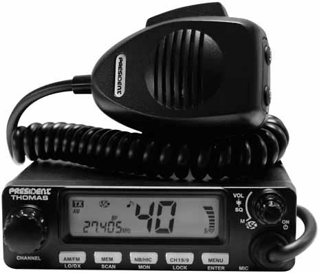
2 Your PRESIDENT THOMAS ASC at a glance 1 - Power and Volume knob (see page 9) 3 - Squelch knob (see page 10) 4 - Display (see page 10) 5 - Channel selector - rotary knob on the unit s and t key on the standard microphone (see page 11) 6 - AM/FM and LO/DX key (see page 11 and 12) 7 - MEM and SCAN key (see page 12 and 13) 8/9 - NB/HIC and MON key (see page 14) 10 - CH19/9 and LOCK key (see page 14 and 15) 11 - MENU and ENTER key (see page 15 and 16) 12 - Microphone plug - RJ45 (see page 16) 13 - PTT - Push To Talk (see page 16) A - Power supply (see page 24) B - Antenna connector C - Jack for external loudspeaker D - Jack for optional vox mike
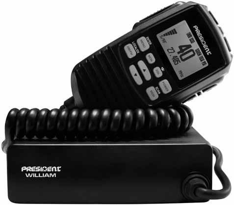
3 Your PRESIDENT WILLIAM ASC at a glance 1 - Power key (see page 9) 2 - Volume s and t key (see page 9) 3 - Squelch key(see page 10) 4 - Display (see page 10) 5 - Channel selector s and t key (see page 11) 6 - AM/FM and LO/DX key (see page 11 and 12) 7 - MEM and SCAN key (see page 12 and 13) 8 - NB/HIC key (see page 14) 9 - MON key (see page 14) 10 - CH19/9 and LOCK key (see page 14 and 15) 11 - MENU and ENTER key (see page 15 and 16) 12 - Microphone plug - RJ45 (see page 16) 13 - PTT - Push To Talk (see page 16) A - Power supply (see page 24) B - Antenna connector C - Jack for external loudspeaker D - Jack for optional vox mike
4 SUMMARY INSTALLATION...6 HOW TO USE YOUR CB...9 TECHNICAL CHARACTERISTICS...25 TROUBLE SHOOTING...25 HOW TO TRANSMIT OR RECEIVE A MESSAGE...25 GLOSSARY...26 CERTIFICATE OF CONFORMITY...28 FREQUENCY TABLES ~ 31 EUROPEAN NORMS...33 WILLIAM remote microphone is optional on THOMAS. This manual explains the features in two parts. THOMAS ASC and WILLIAM ASC. All the features for the WILLIAM ASC or for the THOMAS ASC using the optional remote SPK/MIC are preceded by the icon and writed using this font style. With the WILLIAM ASC or when you use the remote microphone accessory on THOMAS ASC, two items are added at the end of the Menu contents for adjustment of remote microphone features: - DIMMER - LCD CONTRAST 4
5 WARNING! Before using, be careful never transmit without first having connected the antenna (connection "B" situated on the back panel of the equipment) or without having set the SWR (Standing Wave Ratio)! Failure to do so may result in destruction of the power amplifier, which is not covered by the guarantee. MULTI-NORMS TRANSCEIVER! See Configuration setting on page 23 and the Configuration table on page 33. The guarantee of this transceiver is valid only in the country of purchase. 5
6 Welcome to the world of the new generation of CB radios. The new PRESIDENT range gives you access to top performance CB equipment. With the use of up-to-date technology, which guarantees unprecedented quality, your PRESIDENT THOMAS ASC is a new step in personal communication and is the surest choice for the most demanding of professional CB radio users. To ensure that you make the most of all its capacities, we advise you to read carefully this manual before installing and using your PRESIDENT THOMAS ASC CB Radio. A) INSTALLATION 1) WHERE AND HOW TO MOUNT YOUR MOBILE CB RADIO a) You should choose the most appropriate setting from a simple and practical point of view. b) Your CB radio should not interfere with the driver or the passengers. c) Remember to provide for the passing and protection of different wires (e.g. power, antenna, accessory cabling) so that they do not interfere in any way with the driving of the vehicle. d) To install your equipment, use the cradle (1) and the self-tapping screws [2] provided (drilling diameter 3.2 mm). Take care not to damage the vehicle s electrical system while drilling the dash board. e) Do not forget to insert the rubber joints [3] between the CB and its support as these have a shock-absorbing effect which permits gentle orientation and tightening of the set. f) Choose where to place the microphone support and remember that the microphone cord must stretch to the driver without interfering with the controls of the vehicle. - N.B. : As the transceiver has a frontal microphone socket, it can be set into the dash board. In this case, you will need to add an external loud speaker to improve the sound quality of communications (connector EXT.SP situated on the back panel: C). Ask your dealer for advice on mounting your CB radio. MOUNTING DIAGRAM 6
7 2) ANTENNA INSTALLATION a) Choosing your antenna - For CB radios, the longer is antenna, the better its results. Your dealer will be able to help you with your choice of antenna. b) Mobile antenna - Must be fixed to the vehicle where there is a maximum of metallic surface (ground plane), away from windscreen mountings. - If you already have a radio-telephone antenna installed, the CB antenna should be higher than this. - There are two types of antenna: pre-regulated which should be used on a good ground plane (e.g. car roof or lid of the boot), and adjustable which offers a much larger range and can be used on a smaller ground plane (see p. 8 5, Adjustment of SWR). - For an antenna which must be fixed by drilling, you will need a good contact between the antenna and the ground plane. To obtain this, you should lightly scratch the surface where the screw and tightening star are to be placed. - Be careful not to pinch or flatten the coaxial cable (as this runs the risk of break down and/or short-circuiting). - Connect the antenna (B). c) Fixed antenna - A fixed antenna should be installed in as clear space as possible. If it is fixed to a mast, it will perhaps be necessary to stay it, according to the laws in force (you should seek professional advice). All PRESIDENT antennas and accessories are designed to give maximum efficiency to each CB radio within the range. 3) POWER CONNECTION Your PRESIDENT THOMAS ASC is protected against an inversion of polarities. However, before switching it on, you are advised to check all the connections. Your equipment must be supplied with a continued current of 12 volts (A). Today, most cars and lorries are negative earth. You can check this by making sure that the negative terminal of the battery is connected either to the engine block or to the chassis. If this is not the case, you should consult your dealer. WARNING: Lorries generally have two batteries and an electrical installation of 24 volts, in which case it will be necessary to insert a 24/12 volt converter (type CV 24/12 PRESIDENT) into the electrical circuit. The following connection steps should be carried out with the power cable disconnected from the set. a) Check that the battery is of 12 volts. b) Locate the positive and negative terminals of the battery (+ is red and - is black). Should it be necessary to lengthen the power cable, you should use the same or a superior type of cable. c) It is necessary to connect your CB to a permanent (+) and (-). We advise you to connect the power cable directly to the battery (as the connection of the CB cable to the wiring of the car-radio or other parts of the electrical circuit may, in some cases, increase the likelihood of interference). d) Connect the red wire (+) to the positive terminal of the battery and the black (-) wire to the negative terminal of the battery. e) Connect the power cable to your CB radio. OUTPUT RADIUS PATTERNS 7
8 WARNING: Never replace the original fuse (2 A) by one of a different value. 4) BASIC OPERATIONS TO BE CARRIED OUT BEFORE USING YOUR SET FOR THE FIRST TIME (without transmitting and without using the «push-to-talk» switch on the microphone) a) Connect the microphone. b) Check the antenna connections. c) Turn the set on by pushing and holding the POWER knob (1). d) Turn the squelch knob (3) to minimum (M position). e) Adjust the volume to a comfortable level. f) Go to Channel 20 using either the «UP» «DN» key (5) on the microphone or the rotary knob (5). 5) ADJUSTMENT OF SWR (Standing wave ratio) WARNING: This must be carried out when you use your CB radio for the first time (and whenever you re-position your antenna). The adjustment must be carried out in an obstacle-free area. * Adjustment with an external SWR meter (e.g. TOS-1 President) a) To connect the SWR meter : - Connect the SWR meter between the CB radio and the antenna as close as possible to the CB (use a maximum of 40 cm cable, type President CA 2C). b) To adjust the SWR meter: - Set the CB to channel 20 in FM. - Put the switch on the SWR meter to position CAL or FWD. - Press the «push-to-talk» switch on the microphone to transmit. - Bring the index needle to by using the calibration key. - Change the switch to position SWR (reading of the SWR level). The reading on the Meter should be as near as possible to 1. If this is not the case, re-adjust your antenna to obtain a reading as close as possible to 1. (An SWR reading between 1 and 1.8 is acceptable). - It will be necessary to re-calibrate the SWR meter after each adjustment of the antenna. WARNING: In order to avoid any losses and attenuations in cables used for connection between the radio and its accessories, PRESIDENT recommends to use a cable with a length inferior to 3m. Your CB is now ready for use. 8
9 B) HOW TO USE YOUR CB 1) POWER ON/OF CONTROL Push and hold POWER knob (1). THOMAS ASC Current volume and configuration is displayed after 3 seconds WILLIAM ASC Push and hold POWER key (1) of the remote SPK/MIC. Power on/off is switched alternately. Wake up display when remote SPK/MIC is connected 2) VOLUME CONTROL Rotate VOL knob (1). Push VOL s / t key (2) of the remote SPK/MIC. Main unit volume is 43 steps from 0 to 42. But remote SPK/MIC volume is 8 steps from 0 to 7. See Loudspeaker Mute page 24. Rotate VOL knob synch Rotate VOL knob synch 9
10 3) ASC (Automatic Squelch Control) / SQUELCH Suppresses undesirable background noises when there is no communication. Squelch does not affect neither sound nor transmission power, but allows a considerable improvement in listening comfort. a) ASC: AUTOMATIC SQUELCH CONTROL Worldwide patent, a PRESIDENT exclusivity. Turn the SQ knob (3) anti-clockwise into ASC position. THOMAS ASC ASC work (Automatic Squelch Control) WILLIAM ASC Press SQL key (3) on the remote SPK/MIC during 1,5 second ASC appears on the display. No repetitive manual adjustment and a permanent improvement between the sensitivity and the listening comfort when ASC is active. This function can be disconnected by turning the knob clockwise. In this case the squelch adjustment becomes manual again. ASC disappears from the display. SQ knob is active (Analog squelch) b) MANUAL SQUELCH Turn the SQ knob (3) clockwise to the exact point where all background noise disappears. This adjustment should be done with precision as, if set to maximum (fully clockwise), only the strongest signals will be received. With this setting, RSQ (remote squelch function of the remote SPK/MIC) is stopped. c) MANUAL SQUELCH OF REMOTE SPK/MIC Press SQL key (3) on the remote SPK/MIC. The remote squelch level is selectable (3 levels). Push s / t key (5) to select the level. Push ENTER (MENU) key (11) to store the setting. RSQ is displayed. SQLoF SQL-1 SQL-2 SQL-3 SQL - 1 SQL - 2 SQL - 3 SQ knob is inactive. Remote SQ (=digital threshold) is active (Remote squelch RSQ) With this setting, manual squelch function of the main unit is stopped. When the SQL level is OFF, remote squelch is inactive, RSQ disappears and manual squelch knob form the unit (3) is active. Middle strength signal 4) S/RF METER SRF meters indicate the receiving signal strength in RX mode. 10
11 The SRF meter is used as RF power indicator in TX mode. SRF meter indicators are 8 steps from 1 (weak) to 7 (strong), and 0 (no signal). THOMAS ASC Input voice WILLIAM ASC 5) CHANNEL SELECTOR: rotary knob and UP/DN keys of the microphone These switches allow increasing or decreasing a channel. A «beep» sounds each time the channel changes if the Key Beep function is activated. See KEY BEEP function page 21. Rotate Channel knob (5), or push and hold s / t key (5) of standard MIC. Push or push and hold s / t key (5) of remote SPK/MIC. 6) MODE SELECTOR AM/FM ~ LO/DX a) MODE SELECTOR AM/FM (short push) This switch allows selecting the AM or FM modulation. Your modulation mode has to correspond to the one of your correspondent. Amplitude modulation/am: is for communications in areas where there are obstacles and over medium distances. Frequency modulation/fm: for nearby communications in flat, open field. Push AM/FM key (6). Push AM/FM key (6) of the remote SPK/MIC. AM/FM are switched alternately. AM setting FM setting 11

12 AM/FM 2 nd function (only in U configuration) Allows to alternate the frequency bands CEPT and ENG in the U configuration. When the ENG frequency band is selected, UK is displayed. CEPT/ENG are switched alternately. THOMAS ASC Switching of CEPT and ENG in U configuration (ENG - ENGLAND) WILLIAM ASC b) LO/DX (long push 1,5 s) Allows the automatic adjustment of the RF Gain for close communication. Push and hold LO/DX (AM/FM) key (6). LO/DX switching (Local) Push and hold LOCAL/DX (AM/FM) key (6) of the remote SPK/MIC. LO/DX is switched alternately. 7) MEM ~ SCAN a) MEM (short push) Those functions are memorized when memory command is done: Mode AM/FM ~ Channel number ~ CTCSS tone or DCS code. MEM STORE (8 memories) 1. Select the channel to be memorized. 2. Push MEM key (7). 3. With the rotary knob (5) or the s / t key (5) of the standard microphone, select the memory to be stored (number from 1 to 8). 4. Push and hold MEM key (7) to store the selected channel. Memorized data on memory number is displayed for 2 seconds. 5. After 2 seconds the unit returns to usual display. MEM STORE (8 memories) 1. Select the channel to be memorized. 2. Push MEM key (7) of the remote SPK/MIC. 3. With the s / t key (5) of the remote SPK/MIC, select the memory to be stored (number from 1 to 8). 4. Push and hold MEM key (7) of the remote SPK/MIC to store the selected channel. Memorized data on memory number is displayed for 2 seconds. 5. After 2 seconds the remote SPK/MIC returns to usual display. MEMORY Store 1 MEMORY Store 3 MEMORY Store 4 12
13 MEM CALL 1. Push MEM key (7). 2. With the rotary knob (5) or the s / t key (5) of the standard microphone, select the memory to be called (number from 1 to 8). 3. Push MEM key (7) to select the memorized channel. MEM CALL 1. Push MEM key (7) of the remote SPK/MIC in normal RX mode. 2. With the s / t key (5) of the remote SPK/MIC, select the memory to be called (number from 1 to 8). 3. Push MEM key (7) of the remote SPK/MIC to select the memorized channel. MEM CLEAR 1. Clear of all memory is possible by turning on POWER (1) with MEM key (7) push. 2. All memories are cleared at configuration change (see page 23). b) SCAN (long push 1,5 s) THOMAS ASC MEMORY Store 5 WILLIAM ASC There are 2 SCAN types : ALL channels SCAN type (normal), SCAN icon is displayed. MEM channels SCAN type, MEM icon is displayed and SCAN icon is blinking. See page 18 for changing type. Channel research: Allows activating the SCAN function (research of the channels) in an increasing way. The scanning stops as soon as there is a busy channel. The scanning automatically starts 3 seconds after the end of the reception signal and no key is activated during 3 s. The scanning starts again in an increasing way by turning the rotary knob to the right, or in a decreasing way by turning the rotary knob to the left. Push and hold SCAN (MEM) key (7) to start the SCAN. Display of normal SCAN mode Display of memory SCAN mode Push and hold SCAN (MEM) key (7) of the remote SPK/MIC to start the SCAN. Both mode AM/FM are scanned alternately. On the MEM SCAN type, both emergency channels are scanned with the memorized channels. To disable the SCAN function press PTT key (13) or a new long press on SCAN (MEM) key (7). 13
14 8) NB/HIC ~ MON NB/HIC (short push) NB Noise Blanker. These filters allow reducing back ground noises and some reception interferences. «NB» appears on the display when the NB filter is activated. Hi-Cut Eliminates high frequency interferences. Has to be used in accordance with the reception conditions. «HIC» appears on the display when the HI-Cut filter is activated. Push the NB/HIC key (8) to select the filter alternately. Push NB/HIC (8) of the remote SPK/MIC to select the filter alternately. THOMAS ASC Setting Filter NB + HIC WILLIAM ASC NB OFF, HIC OFF NB OFF, HIC ON NB ON, HIC OFF NB ON, HIC ON 9) MON (long push 1,5 s) Setting transmission of MON The MON function deactivates the squelch function, it is used for fast listening. It works with analogic squelch, ASC, RSQ squelch. Push and hold MON (NB/HIC) key (8) to activate the MON function. Short push MON key (9) of the remote SPK/MIC to activate the MON function. It works with analogic squelch, ASC, RSQ squelch. MON function on/off alternately. While this function is active MON icon blinks and BUSY icon lights. 10) CH19/9 ~ LOCK Channel transition of emergency calling a) CH19/9 (short push) Push CH19/9 key (10) to active instantly these emergency channels. Push CH19/9 key (10) of the remote SPK/MIC to active instantly these emergency channels. CURRENT CHANNEL CH 19 (AM) CH9 (AM) 14
15 b) LOCK (long push 1,5 s) Push and hold LOCK (CH19/9) key (10) to lock the unit and remote SPK/MIC. Following functions are active even if the LOCK function is active: PTT key (13), SQ knob (3), VOL and POWER knob (1). Push and hold LOCK (CH19/9) key (10) of the remote SPK/MIC to lock the remote SPK/MIC and the unit. Following functions are active even if the LOCK function is active : PTT key (13), SQL key (2), VOL s / t key (2) and POWER key (1). THOMAS ASC Key Lock on WILLIAM ASC 11) MENU ~ ENTER a) MENU (short push) Push MENU key (10) to active the MENU mode. Push MENU key (10) of the remote SPK/MIC to active the MENU mode. Press MENU key (10) once more, current setting is stored and menu changes from next setting (see table). If no setting is done during 10 seconds, the unit exits from MENU mode. Nº MENU Item Effective area Selectable item Page a CTCSS/DCS setting /CH Off, CTCSS: 1 to 38, DCS: 1 to b SCAN TYPE setting /CH On/off 18 c VOX SENSITIVITY LEVEL /UNIT off, 1 to 9 18 d ANTI VOX LEVEL /UNIT 0 to 9 19 e VOX DELAY TIME /UNIT 1 to 9 (0.2, 0.4, 0.6, 0.8, 1, 1.2, 1.5, 2, 3 seconds) 19 f ROGER BEEP /UNIT on/off 20 g KEY BEEP /UNIT on/off 21 h BACK LIGHT COLOUR (2) /MAIN UNIT Orange (o) / Green (G) 21 i DIMMER (1) /Remote SPK/MIC off, LO, HI 22 j LCD CONTRAST (1) /Remote SPK/MIC 1 to (1) DIMMER and LCD contrast setting appear on THOMAS only when optional remote SPK/MIC is connected. Thus if is not connected, selectable menu items are from a to h. (2) Function doesn t work on the remote SPK/MIC. This function does not exist on WILLIAM ASC. Items change from g to i. See the function features on the indicated page. 15
16 b) ENTER (long push 1,5 s) Push and hold ENTER (MENU) key (10) to complete the setting and exit the MENU mode. Push and hold ENTER (MENU) key (10) of the remote SPK/MIC to complete the setting and exit the MENU mode. 12) MICRO PLUG RJ45 The plug is located on the front panel of the transceiver and makes the setting of the equipment into the dashboard easier. Push 1, pull 2 to remove THOMAS ASC WILLIAM ASC See cabling diagram page ) TRANSMISSION a) PTT Transmission key (13), press to transmit a message, is displayed and release to listen to an incoming communication. PTT Transmission VOX Transmission Transmission key (13) of the remote SPK/MIC, press to transmit a message, is displayed and release to listen to an incoming communication. To transmit, you can also use the VOX function. b) VOX TRANSMISSION The VOX function allows transmitting by speaking into the original microphone (or in the optional vox microphone) without pressing the PTT switch. When the VOX function is activate «VOX» is displayed. The use of an optional vox mike connected to the rear panel of the transceiver (D) disables the original microphone. Limit of continuous transmission is 5 minutes in VOX TX mode. If it is over, a radio mode changes to VOX transmission error condition automatically. Following three parameters are selectable in menu mode: VOX sensitivity - Anti VOX level - VOX delay time. Transmission Error Transmission Error by ANTI Vox The VOX function mute the loudspeaker of the WILLIAM remote SPK/MIC. See the VOX Setting parameters on page18. 16
 and DCS (Digital Codes Squelch) are two tone squelch methods, they replace the manual squelch and simultaneously function similar to a selective call")
17 14) MENU FUNCTIONS If no setting is done during 10 seconds, the unit exits from MENU mode. a) CTCSS / DCS CTCSS and DCS can be set on FM mode only. CTCSS (Continuous Tone Coded Squelch System) and DCS (Digital Codes Squelch) are two tone squelch methods, they replace the manual squelch and simultaneously function similar to a selective call system. Squelch functions often depend on the field strength or are controlled via the signal-to-noise ratio. This means that they always depend on the varying conditions of reception. Each transmission on the selected channel and each interference carrier as well will open the squelch. All radios belonging to a certain speech circuit have to be operated using the same CTCSS frequency or the same DCS code. The squelch of the receiving radio only opens when a signal featuring the corresponding CTCSS/DCS is received. The manual squelch and ASC are switched off. CTCSS and DCS still function when the signal is already very weak and has a considerable background noise. 38 CTCSS tones and 104 DCS codes are available. Push the MENU key (11) one time. Current CTCSS/DCS setting is displayed. Rotate the Channel knob (5) or push s/t key (5) of the standard microphone to select the CTCSS tone or DCS code. of CTCSS (1 to 38) DCS (1 to104) off CTCSS (1 to 38) DCS (1 to104) THOMAS ASC DCS/CTCSS code select WILLIAM ASC Push MENU key (11). Current setting is stored and menu setting changes to next. Push and hold ENTER (MENU) key (11) to exit from the mode MENU. Push the MENU key (11) of the remote SPK/MIC one time. Current CTCSS/DCS setting is displayed. Push s/t key (5) of the remote SPK/ MIC to select the CTCSS tone or DCS code. Push MENU key (11) of the remote SPK/MIC. Current setting is stored and menu setting changes to next. Push and hold ENTER (MENU) key (11) of the remote SPK/MIC to store and exit from the mode MENU. 17
 or push s/t key (5) of the standard microphone to select the SCAN type. Push MENU key (11). Current setting is stored and menu setting changes to next.")
18 See CTCSS Tone List and DSC Code List page 32. b) SCAN TYPE Push the MENU key (11) two times. Current SCAN type setting is displayed. Rotate the Channel knob (5) or push s/t key (5) of the standard microphone to select the SCAN type. Push MENU key (11). Current setting is stored and menu setting changes to next. Push and hold ENTER (MENU) key (11) to exit from the mode MENU. Push the MENU key (11) of the remote SPK/MIC two times. Current SCAN type setting is displayed. Push s / t key (5) of the remote SPK/ MIC to select the SCAN type. Push MENU key (11) of the remote SPK/MIC. Current setting is stored and menu setting changes to next. Push and hold ENTER (MENU) key (11) of the remote SPK/MIC to store and exit from the mode MENU. SCAN MEM on SCAN MEM of THOMAS ASC SCAN type select WILLIAM ASC See SCAN function page 13. c) VOX SENSITIVITY LEVEL - SL The VOX Sensitivity Level allows the adjustment of the microphone (original one or optional vox) for an optimum transmission quality. Adjustable level : of (Off), from1 (high level) to 9 (low level). Push the MENU key (11) three times. Current VOX SENSITIVITY setting is displayed. Rotate the Channel knob (5) or push s/t key (5) of the standard microphone to select the VOX SENSITIVITY. Push MENU key (11). Current setting is stored and menu setting changes to next. Push and hold ENTER (MENU) key (11) to exit from the mode MENU. Push the MENU key (11) of the remote SPK/MIC three times. Current VOX SENSITIVITY setting is displayed. Push s / t key (5) of the remote SPK/MIC to select the VOX SENSITIVITY. Push MENU key (11) of the remote SPK/MIC. Current setting is stored and menu setting changes to next. Push and hold ENTER (MENU) key (11) of the remote SPK/MIC to store and exit from the mode MENU. When VOX function is active while a remote SPK/MIC is connected, speaker of remote SPK/MIC is always muted. VOX Sensitive select 18
 ANTI VOX LEVEL - al ANTI VOX function checks speaker volume and inhibits VOX transmission.")
19 VOX SL of VOX SL1... VOX SL 9 VOX SENS of VOX SENS 1... VOX SENS 9 THOMAS ASC WILLIAM ASC VOX transmission is limited until 5 minutes. If one transmission is over 5 minutes, a radio condition is changed to TX error condition. d) ANTI VOX LEVEL - al ANTI VOX function checks speaker volume and inhibits VOX transmission. This is to prevent an easy loop from speaker sound to MIC. When anti VOX inhibition works, VOX icon blinks. The level is adjustable from 0 (Off) to 9 (low level). Push the MENU key (11) four times. Current ANTI VOX setting is displayed. Rotate the Channel knob (5) or push s/t key (5) of the standard microphone to select the ANTI VOX LEVEL. Push MENU key (11). Current setting is stored and menu setting changes to next. Push and hold ENTER (MENU) key (11) to exit from the mode MENU. Push the MENU key (11) of the remote SPK/MIC four times. Current ANTI VOX LEVEL setting is displayed. Push s / t key (5) of the remote SPK/MIC to select the ANTI VOX LEVEL. Push MENU key (11) of the remote SPK/MIC. Current setting is stored and menu setting changes to next. Push and hold ENTER (MENU) key (11) of the remote SPK/MIC to store and exit from the mode MENU. VOX AL 0 (OFF) VOX AL 1... VOX AL 9 ANTI VOX 0 (OFF) ANTI VOX 1... ANTI VOX 9 ANTI VOX Level select e) VOX DELAY TIME - dt VOX delay time is max wait time from the end of transmission request to actual end of transmission. If transmission request is detected in delay time, transmission will be done without pause. Push the MENU key (11) five times. Current VOX DELAY TIME setting is displayed. Rotate the Channel knob (5) or push s/t key (5) of the standard microphone to select the VOX DELAY TIME (from 1 to 9). VOX Delay Time select 19
 of the remote SPK/MIC to select the VOX DELAY TIME (form 1 to 9). Push MENU key (11) of the remote SPK/MIC.")
20 Push MENU key (11). Current setting is stored and menu setting changes to next. Push and hold ENTER (MENU) key (11) to exit from the mode MENU. Push the MENU key (11) of the remote SPK/MIC five times. Current VOX DELAY TIME setting is displayed. Push s / t key (5) of the remote SPK/MIC to select the VOX DELAY TIME (form 1 to 9). Push MENU key (11) of the remote SPK/MIC. Current setting is stored and menu setting changes to next. Push and hold ENTER (MENU) key (11) of the remote SPK/MIC to store and exit from the mode MENU. VOX dt1 VOX dt 2... VOX dt 9 VOXDELAY 1 VOXDELAY 2... VOXDELAY 9 THOMAS ASC VOX Delay Time select WILLIAM ASC f) ROGER BEEP ROGER BEEP is a short tone that is transmitted at the end of transmission. When the ROGER BEEP function is active is displayed. Push the MENU key (11) six times. Current ROGER BEEP setting is displayed. Rotate the Channel knob (5) or push s/t key (5) of the standard microphone to select the ROGER BEEP setting (ON/ OFF). Push MENU key (11). Current setting is stored and menu setting changes to next. Push and hold ENTER (MENU) key (11) to exit from the mode MENU. Push the MENU key (11) of the remote SPK/MIC six times. Current ROGER BEEP setting is displayed. Push s / t key (5) of the remote SPK/MIC to select the ROGER BEEP setting (ON/OFF). Push MENU key (11) of the remote SPK/MIC. Current setting is stored and menu setting changes to next. Push and hold ENTER (MENU) key (11) of the remote SPK/MIC to store and exit from the mode MENU. ROGER BEEP setting of ROGER of on ROGER on 20
 or push s/t key (5) of the standard microphone to select the KEY BEEP setting (ON/OFF). Push MENU key (11). Current setting is stored and menu setting changes to next.")
 of the remote SPK/ MIC to select the KEY BEEP setting (ON/OFF). Push MENU key (11) of the remote SPK/MIC. Current setting is stored and menu setting changes to next.")
21 Transmitting roger beep can be heard through the speaker. g) KEY BEEP When the KEY BEEP function is active BP is displayed. Push the MENU key (11) seven times. Current KEY BEEP setting is displayed. Rotate the Channel knob (5) or push s/t key (5) of the standard microphone to select the KEY BEEP setting (ON/OFF). Push MENU key (11). Current setting is stored and menu setting changes to next. Push and hold ENTER (MENU) key (11) to exit from the mode MENU. Push the MENU key (11) of the remote SPK/MIC seven times. Current KEY BEEP setting is displayed. Push s / t key (5) of the remote SPK/ MIC to select the KEY BEEP setting (ON/OFF). Push MENU key (11) of the remote SPK/MIC. Current setting is stored and menu setting changes to next. Push and hold ENTER (MENU) key (11) of the remote SPK/MIC to store and exit from the mode MENU. BP of BP on BP BEEP of BP BEEP on THOMAS ASC KEY BEEP setting WILLIAM ASC When Key Beep function is off, Roger Beep can t be heard through speaker but actual transmission is done automatically. h) BACK LIGHT COLOUR (THOMAS only) This function does not work with the display of the remote SPK/ MIC. Push the MENU key (11) eight times. Current COLOUR setting is displayed. Rotate the Channel knob (5) or push s/t key (5) of the standard microphone to select the COLOUR of the main unit display (GREEN/ORANGE). Push MENU key (11). Current setting is stored and menu setting changes to next. Push and hold ENTER (MENU) key (11) to exit from the mode MENU. Push the MENU key (11) of the remote SPK/MIC eight times. Current COLOUR setting is displayed. Push s / t key (5) of the remote SPK/ MIC to select the COLOUR of the main unit display (GREEN/ORANGE). BACK LIGHT Color setting 21
 DIMMER (WILLIAM only) This function does not work with the display of the main unit.")
 to select the DIMMER of the remote SPK/MIC display. Push MENU key (11). Current setting is stored and menu setting changes to next.")
22 Push MENU key (11) of the remote SPK/MIC. Current setting is stored and menu setting changes to next. Push and hold ENTER (MENU) key (11) of the remote SPK/MIC to store and exit from the mode MENU. THOMAS ASC WILLIAM ASC Color GREEN Color o ORANGE i) DIMMER (WILLIAM only) This function does not work with the display of the main unit. The DIMMER function changes the intensity of the back light of the remote SPK/MIC. OFF (no back light), LOW or HIGH intensity. Push the MENU key (11) nine times. Current DIMMER setting is displayed. Rotate the Channel knob (5) to select the DIMMER of the remote SPK/MIC display. Push MENU key (11). Current setting is stored and menu setting changes to next. Push and hold ENTER (MENU) key (11) to exit from the mode MENU. DIMMER setting Push the MENU key (11) of the remote SPK/MIC nine times. Current DIMMER setting is displayed. Push s / t key (5) of the remote SPK/ MIC to select the DIMMER of the remote SPK/MIC display. Push MENU key (11) of the remote SPK/MIC. Current setting is stored and menu setting changes to next. Push and hold ENTER (MENU) key (11) of the remote SPK/MIC to store and exit from the mode MENU. LI HT of LI HT Lo LI HT HI LIGHT of LIGHT Lo LIGHT HI j) LCD CONTRAST (WILLIAM only) This function does not work with the display of the main unit. The CONTRAST function changes the contrast (from 1 to 10 ) between the back light and the characters on the remote SPK/MIC. Push the MENU key (11) ten times. Current CONTRAST setting is displayed. Rotate the Channel knob (5) to select the CONTRAST level of the remote SPK/MIC display. 22
 of the remote SPK/ MIC to select the CONTRAST level of the remote SPK/MIC display. Push MENU key (11) of the remote SPK/MIC.")
 CONFIGURATION (configuration: EU; PL; d: EC; U) The frequency bands have to be chosen according to the country of use.")
23 Push MENU key (11). Current setting is stored and menu setting changes to next. Push and hold ENTER (MENU) key (11) to exit from the mode MENU. Push the MENU key (11) of the remote SPK/MIC ten times. Current CONTRAST setting is displayed. Push s / t key (5) of the remote SPK/ MIC to select the CONTRAST level of the remote SPK/MIC display. Push MENU key (11) of the remote SPK/MIC. Current setting is stored and menu setting changes to next. Push and hold ENTER (MENU) key (11) of the remote SPK/MIC to store and exit from the mode MENU. ConT1 Cont 2... ConT10 CONTRAST 1 CONTRAST 2... CONTRAST 10 THOMAS ASC CONTRAST setting WILLIAM ASC 15) CONFIGURATION (configuration: EU; PL; d: EC; U) The frequency bands have to be chosen according to the country of use. Don t use any other configuration. Some countries need a user s licence. See table page 34. Proceeding 1. Turn POWER (1) on with the MENU (11) key push. ConF and current setting are displayed. 2. Push MENU (11) key. ConF and current setting start blinking. 3. Rotate Channel knob (5) or push s/t key of standard microphone to select new setting. 4. Push MENU (11) key. New setting is stored and ConF and current setting turn to light on LCD. Proceeding 1. Turn POWER (1) on with the MENU (11) key push of the remote SPK/ MIC. CONFIG and current setting are displayed. 2. Push MENU (11) key of the remote SPK/MIC. CONFIG and current setting start blinking. CONFIGURATION setting - 1 CONFIGURATION setting - 2 CONFIGURATION setting

24 3. Push s/t key (5) of the remote SPK/MIC to select new setting. 4. Push MENU (11) key of the remote SPK/MIC. New setting is stored and CONFIG and current setting turn to light on LCD. At this point, confirm the selection by switching off the transceiver and then switching it on again. ConF EU ConF PL ConF d ConF EC Conf U CONFIG EU CONFIG PL CONFIG d CONFIG EC CONFIG U THOMAS ASC CONFIGURATION setting - 4 WILLIAM ASC See the frequency bands table pages 29 ~ 31 / configuration page 33 16) LOUDSPEAKER MUTE The loudspeaker of the unit can be muted. Turn POWER (1) on with the NB/HIC (8) key push. Turn POWER (1) on with the MON (9) key push. Speaker on/off condition is changed alternately. When the speaker is muted, rotate the VOLUME knob (1) or push the VOL s / t key (2) of the remote SPK/MIC always displays UoL 00 on the THOMAS. Volume is increased or decreased on the WILLIAM display. VOLUME displays with loudspeaker muted Rotate VOL knob A) POWER SUPPLY (13.2 V) B) ANTENNA CONNECTOR (SO-239) C) JACK FOR EXTERNAL LOUDSPEAKER (8 Ω, Ø 3,5 mm) D) JACK FOR OPTIONAL VOX MIKE (Ø 2,5 mm) 24
25 C) TECHNICAL CHARACTERISTICS 1) GENERAL - Channels : 40 - Modulation modes : AM/FM - Frequency ranges : from MHz to MHz - CTCSS Tones : 38 - DCS codes : Antenna impedance : 50 ohms - Power supply : 13.2 V - Dimensions (in mm) : 125 (L) x 38 (H) x 103 (D) - Weight : ~ 0.7 kg - Accessories supplied : Electret microphone with support, mounting cradle, screws. - Filter : ANL (Automatic Noise Limiter) built-in 2) TRANSMISSION - Frequency allowance : +/- 200 Hz - Carrier power : 4 W AM / 4 W FM - Transmission interference : inferior to 4 nw (- 54 dbm) - Audio response : 300 Hz to 3 KHz - Emitted power in the adj. channel : inferior to 20 µw - Microphone sensitivity : 7 mv - Drain : 1,8 A (with modulation) - Modulated signal distortion : 2 % 3) RECEPTION - Maxi. sensitivity at 20 db sinad : AM / 0.5 µv dbm FM / 0,35 µv dbm - Frequency response : 300 Hz to 3 khz - Adjacent channel selectivity : 60 db - Maximum audio power : 2 W - Squelch sensitivity : minimum 0.2 µv dbm maximum 1 mv - 47 dbm - Frequency image rejection rate : 60 db - Intermediate frequency rej. rate : 70 db - Drain : 300 ma nominal / 750 ma maximum D) TROUBLE SHOOTING 1) YOUR CB RADIO WILL NOT TRANSMIT OR YOUR TRANSMISSION IS OF POOR QUALITY - Check that the antenna is correctly connected and that the SWR is properly adjusted. - Check that the microphone is properly plugged in. - Check that the programmed configuration is the correct one (see table page 33). 2) YOUR CB RADIO WILL NOT RECEIVE OR RECEPTION IS POOR - Check that LOCAL DX (6) is off. - Check that the squelch level is properly adjusted. - Check that the programmed configuration is the correct one (see table page 33). - Check that the volume is set to a comfortable listening level. - Check that the antenna is correctly connected and that the SWR is properly adjusted. - Check that you are using the same modulation mode as your correspondent. - Check the use of a CTCSS tone or a DSC code. 3) YOUR CB WILL NOT LIGHT UP - Check the power supply. - Check the connection wiring. - Check the fuse. E) HOW TO TRANSMIT OR RECEIVE A MESSAGE Now that you have read the manual, make sure that your CB Radio is ready for use (i.e. check that your antenna is connected). Choose your channel (19, 27). Choose your mode (AM/FM) which must be the same as that of your correspondent. Press the «push-to-talk» switch and announce your message «Attention stations, transmission testing» which will allow you to check the clearness and the power of your signal. Release the switch and wait for a reply. You should receive a reply like, «Strong and clear». If you use a calling channel (19, 27) and you have established communication 25
26 with someone, it is common practice to choose another available channel so as not to block the calling channel. F) GLOSSARY Below you will find some of the most frequently used CB radio expressions. Remember this is meant for fun and that you are by no means obliged to use them. In an emergency, you should be as clear as possible. INTERNATIONAL PHONETIC ALPHABET A Alpha H Hotel O Oscar V Victor B Bravo I India P Papa W Whiskey C Charlie J Juliett Q Quebec X X-ray D Delta K Kilo R Romeo Y Yankee E Echo L Lima S Sierra Z Zulu F Foxtrott M Mike T Tango G Golf N November U Uniform TECHNICAL VOCABULARY AM CB CH CW DX DW FM GMT HF LF LSB RX SSB SWR SWL SW TX UHF USB VHF : Amplitude Modulation : Citizen s Band : Channel : Continuous Wave : Long Distance Liaison : Dual Watch : Frequency Modulation : Greenwich Meantime : High Frequency : Low Frequency : Lower Side Band : Receiver : Single Side Band : Standing Wave Ratio : Short Wave Listening : Short Wave : CB Transceiver : Ultra High Frequency : Upper Side Band : Very High Frequency CB LANGUAGE Advertising : Flashing lights of police car Back off : Slow down Basement : Channel 1 Base station : A CB set in fixed location Bear : Policeman Bear bite : Speeding fine Bear cage : Police station Big slab : Motorway Big 10-4 : Absolutely Bleeding : Signal from an adjacent channel interfering with the transmission Blocking the channel : Pressing the PTT switch without talking Blue boys : Police Break : Used to ask permission to join a conversation Breaker : A CBer wishing to join a channel Clean and green : Clear of police Cleaner channel : Channel with less interference Coming in loud and proud : Good reception Doughnut : Tyre Down and gone : Turning CB off Down one : Go to a lower channel Do you copy? : Understand? DX : Long distance Eighty eights : Love and kisses Eye ball : CBers meeting together Good buddy : Fellow CBer Hammer : Accelerator Handle : CBer s nickname Harvey wall banger : Dangerous driver How am I hitting you? : How are you receiving me? Keying the mike : Pressing the PTT switch without talking Kojac with a kodak : Police radar Land line : Telephone Lunch box : CB set Man with a gun : Police radar Mayday : SOS Meat wagon : Ambulance Midnight shopper : Thief Modulation : Conversation Negative copy : No reply Over your shoulder : Right behind you 26
27 Part your hair Pull your hammer back Rat race Rubberbander Sail boat fuel Smokey dozing Smokey with a camera Spaghetti bowl Stinger Turkey Up one Wall to wall What am I putting to you? : Behave yourself - police ahead : Slow down : Congested traffic : New CBer : Wind : Parked police car : Police radar : Interchange : Antenna : Dumb CBer : Go up one channel : All over/everywhere : Please give me an S-meter reading. 27
28 CERTIFICATE OF CONFORMITY CERTIFICATE OF CONFORMITY We, GROUPE PRESIDENT ELECTRONICS, Route de Sète, BP Balaruc FRANCE, declare, on our own responsibility that the CB radio-communication transceiver Brand : PRESIDENT Model : THOMAS Manufactured in PRC is in conformity with the essential requirements of the Directive 1999/5/CE (Article 3) adapted to the national law, as well as with the following European Standards: We, GROUPE PRESIDENT ELECTRONICS, Route de Sète, BP Balaruc FRANCE, declare, on our own responsibility that the CB radio-communication transceiver Brand : PRESIDENT Model : WILLIAM Manufactured in PRC is in conformity with the essential requirements of the Directive 1999/5/CE (Article 3) adapted to the national law, as well as with the following European Standards: Balaruc, the 16 april 2012 EN V1.3.1 ( ) EN V1.3.1 ( ) EN V1.8.1 (2010-1) EN V1.2.1 (2002-8) EN (1996) Balaruc, the 14 may 2012 EN V1.3.1 ( ) EN V1.3.1 ( ) EN V1.8.1 (2010-1) EN V1.2.1 (2002-8) EN (1996) Jean-Gilbert MULLER General Manager Jean-Gilbert MULLER General Manager 28
29 FREQUENCY TABLE for EU / EC / U (CEPT) FREQUENCY TABLE for PL Channel Frequency Channel Frequency 1 26,965 MHz 21 27,215 MHz 2 26,975 MHz 22 27,225 MHz 3 26,985 MHz 23 27,255 MHz 4 27,005 MHz 24 27,235 MHz 5 27,015 MHz 25 27,245 MHz 6 27,025 MHz 26 27,265 MHz 7 27,035 MHz 27 27,275 MHz 8 27,055 MHz 28 27,285 MHz 9 27,065 MHz 29 27,295 MHz 10 27,075 MHz 30 27,305 MHz 11 27,085 MHz 31 27,315 MHz 12 27,105 MHz 32 27,325 MHz 13 27,115 MHz 33 27,335 MHz 14 27,125 MHz 34 27,345 MHz 15 27,135 MHz 35 27,355 MHz 16 27,155 MHz 36 27,365 MHz 17 27,165 MHz 37 27,375 MHz 18 27,175 MHz 38 27,385 MHz 19 27,185 MHz 39 27,395 MHz 20 27,205 MHz 40 27,405 MHz Channel Frequency Channel Frequency 1 26,960 MHz 21 27,210 MHz 2 26,970 MHz 22 27,220 MHz 3 26,980 MHz 23 27,250 MHz 4 27,000 MHz 24 27,230 MHz 5 27,010 MHz 25 27,240 MHz 6 27,020 MHz 26 27,260 MHz 7 27,030 MHz 27 27,270 MHz 8 27,050 MHz 28 27,280 MHz 9 27,060 MHz 29 27,290 MHz 10 27,070 MHz 30 27,300 MHz 11 27,080 MHz 31 27,310 MHz 12 27,100 MHz 32 27,320 MHz 13 27,110 MHz 33 27,330 MHz 14 27,120 MHz 34 27,340 MHz 15 27,130 MHz 35 27,350 MHz 16 27,150 MHz 36 27,360 MHz 17 27,160 MHz 37 27,370 MHz 18 27,170 MHz 38 27,380 MHz 19 27,180 MHz 39 27,390 MHz 20 27,200 MHz 40 27,400 MHz 29
30 FREQUENCY TABLE for d Channel Frequency Channel Frequency 1 26,965 MHz 21 27,215 MHz 2 26,975 MHz 22 27,225 MHz 3 26,985 MHz 23 27,255 MHz 4 27,005 MHz 24 27,235 MHz 5 27,015 MHz 25 27,245 MHz 6 27,025 MHz 26 27,265 MHz 7 27,035 MHz 27 27,275 MHz 8 27,055 MHz 28 27,285 MHz 9 27,065 MHz 29 27,295 MHz 10 27,075 MHz 30 27,305 MHz 11 27,085 MHz 31 27,315 MHz 12 27,105 MHz 32 27,325 MHz 13 27,115 MHz 33 27,335 MHz 14 27,125 MHz 34 27,345 MHz 15 27,135 MHz 35 27,355 MHz 16 27,155 MHz 36 27,365 MHz 17 27,165 MHz 37 27,375 MHz 18 27,175 MHz 38 27,385 MHz 19 27,185 MHz 39 27,395 MHz 20 27,205 MHz 40 27,405 MHz Channel Frequency Channel Frequency 41 26,565 MHz 61 26,765 MHz 42 26,575 MHz 62 26,775 MHz 43 26,585 MHz 63 26,785 MHz 44 26,595 MHz 64 26,795 MHz 45 26,605 MHz 65 26,805 MHz 46 26,615 MHz 66 26,815 MHz 47 26,625 MHz 67 26,825 MHz 48 26,635 MHz 68 26,835 MHz 49 26,645 MHz 69 26,845 MHz 50 26,655 MHz 70 26,855 MHz 51 26,665 MHz 71 26,865 MHz 52 26,675 MHz 72 26,875 MHz 53 26,685 MHz 73 26,885 MHz 54 26,695 MHz 74 26,895 MHz 55 26,705 MHz 75 26,905 MHz 56 26,715 MHz 76 26,915 MHz 57 26,725 MHz 77 26,925 MHz 58 26,735 MHz 78 26,935 MHz 59 26,745 MHz 79 26,945 MHz 60 26,755 MHz 80 26,955 MHz 30
31 FREQUENCY TABLE for U (ENG) THOMAS RJ45 MICROPHONE PLUG Channel Frequency Channel Frequency 1 27,60125 MHz 21 27,80125 MHz 2 27,61125 MHz 22 27,81125 MHz 3 27,62125 MHz 23 27,82125 MHz 4 27,63125 MHz 24 27,83125 MHz 5 27,64125 MHz 25 27,84125 MHz 6 27,65125 MHz 26 27,85125 MHz 7 27,66125 MHz 27 27,86125 MHz 8 27,67125 MHz 28 27,87125 MHz 9 27,68125 MHz 29 27,88125 MHz 10 27,69125 MHz 30 27,89125 MHz 11 27,70125 MHz 31 27,90125 MHz 12 27,71125 MHz 32 27,91125 MHz 13 27,72125 MHz 33 27,92125 MHz 14 27,73125 MHz 34 27,93125 MHz 15 27,74125 MHz 35 27,94125 MHz 16 27,75125 MHz 36 27,95125 MHz 17 27,76125 MHz 37 27,96125 MHz 18 27,77125 MHz 38 27,97125 MHz 19 27,78125 MHz 39 27,98125 MHz 20 27,79125 MHz 40 27,99125 MHz 1- SHIELD 2 - YELLOW 3 - NC 4 - NC 5 - NC 6 - BLACK 7 - NC 8 - RED 31
32 CTCSS Tone List DCS Code List No. Freq. (Hz) No. Freq. (Hz) No. Freq. (Hz) 00 - of OFF Code DCS Code DCS Code DCS Code DCS No. (Octal) No. (Octal) No. (Octal) No. (Octal)
33 Normes Européennes - Normas Europeas - European Norms - normy europejskie The frequency band and the transmission power of your transceiver must correspond with the configuration authorized in the country where it is used. Note: In U configuration : In order to select the frequency band ENG/CEPT. Push the AM/FM key (6). When the frequency band is ENG, UK appears on the display. When the frequency band is CEPT UK disappears from the display. 33
34 Please see updated table on website page «The CB radios» then «President Radio CB and Europe». 34
35
36 SIEGE SOCIAL/HEAD OFFICE - FRANCE Route de Sète - BP BALARUC Site Internet : groupe@president-electronics.com U01UT391ZZA(0) 1251/03-12
Your PRESIDENT GRANT II ASC at a glance
 Owner's manual Your PRESIDENT GRANT II ASC at a glance SUMMARY INSTALLATION HOW TO USE YOUR CB TECHNICAL CHARACTERISTICS TROUBLE SHOOTING HOW TO TRANSMIT OR RECEIVE A MESSAGE GLOSSARY CERTIFICATE OF CONFORMITY
Owner s manual 12/24 V
 Owner s manual 12/24 V Your PRESIDENT BARRY ASC FM 12/24 V at a glance SUMMARY English INSTALLATION 5 HOW TO USE YOUR CB 7 FUNCTIONS TURNING ON THE UNIT 9 FUNCTIONS WITH PTT PEDAL 10 TECHNICAL CHARACTERISTICS
WARNING WELCOME TO USE RESET
 WARNING Please install the antenna (connect to the location B on the back panel of the radio) and set the SWR (Standing Wave Ratio) before transmitting. Failure to do so may result in destruction of the
Downloaded from
 Downloaded from www.cbradio.nl WARNING Please install the antenna (connect to the location B in the back panel of the radio) and set the SWR (Standing Wave Ratio) before transmitting. Otherwise it may
User Manual. Specifications...3. Control and Operation Microphone...8. Installation...9. Installation of Main Unit...9
 Contents Specifications...3 Control and Operation...4-7 Microphone...8 Installation...9 Installation of Main Unit...9 Antenna Installation...9 Operational test...9 Frequency Bands Table...10 Frequency
Midland 248XL I NSTRUCTION GUI DE
 Midland 248XL I NSTRUCTION GUI DE INDEX Introduction...2 Function and location of the controls...3 Installation...7 Power supply...7 Installing an antenna...7 How to use your Midland 248XL...8 Frequency
CON NEX HP. OWNER'S MANUAL Full Channel AM/FM Amateur Mobile Transceiver TABLE OF CONTENTS TUNING THE ANTENNA FOR OPTIMUM S.W.R..
 TABLE OF CONTENTS PAGE SPECIFICATIONS... 2 INSTALLATION... 3 LOCATION... 3 CON NEX - 4300HP MOUNTING THE RADIO... 3 IGNITION NOISE INTERFERENCE... 4 ANTENNA... 4 TUNING THE ANTENNA FOR OPTIMUM S.W.R..
Introduction Pag. 1. Function and location of the controls Pag. 2. Installation Pag. 3. Power supply Pag. 3. Installing an antenna Pag.
 ALAN 121 INDEX Introduction Pag. 1 E N G L I S H Function and location of the controls Pag. 2 Installation Pag. 3 Power supply Pag. 3 Installing an antenna Pag. 4 How to operate with your transceiver Pag.
4W MOBILE CB TRANSCEIVER INSTRUCTION MANUAL
 4W MOBILE CB TRANSCEIVER INSTRUCTION MANUAL www.ttikorea.co.kr CONTENTS 1. Introduction 2. Supplied Accessories 3. Installation 4. Transceiver Controls and Functions 1) Microphone Jack 2) LCD Display 3)
4W MOBILE CB TRANSCEIVER INSTRUCTION MANUAL
 4W MOBILE CB TRANSCEIVER INSTRUCTION MANUAL www.ttikorea.co.kr CONTENTS 1. Introduction 2. Supplied Accessories 3. Installation 4. Transceiver Controls and Functions 1) Channel Selector 2) Dual Watch 3)
DC-1122 Compact 5W UHF CB Radio
 DC-1122 Compact 5W UHF CB Radio Instruction Manual Introduction! NOTE Use of the citizen band radio service is licensed in Australia by ACMA Radio communications (Citizen Band Radio Stations) Class Licence
HR MHZ AM-FM AMATEUR RADIO HF TRANSCEIVER OWNER'S MANUAL. Content of the packaging
 HR-2800 28 MHZ AM-FM AMATEUR RADIO HF TRANSCEIVER OWNER'S MANUAL NOTICE! It is recommended to carefully read this owner s manual before using the product. This will also help to prevent illegal use of
WILSON. Manuel d'utilisation / Manual del usuario Owner's manual / Handbuch
 WILSON Manuel d'utilisation / Manual del usuario Owner's manual / Handbuch Votre PRESIDENT WILSON ASC en un coup d'oeil Un vistazo a vuestro PRESIDENT WILSON ASC Your PRESIDENT WILSON ASC at a glance 2
AT-5555N 10 METER RADIO
 AT-5555N 10 METER RADIO CONTENTS FUNCTIONS & FEATURES...1 STANDARD ACCESSORIES...2 INSTALLATION...2 GETTING ACQUAINTED...5 HOW TO USE YOUR RADIO...7 KEYPAD FUNCTION...9 BACKGROUND FUNCTION MENU OPERATION...12
RCI-6300F25/150. Owner's Manual. AM/FM Amateur Transceiver With Built-in Frequency Counter. Table of Contents. Downloaded from
 Table of Contents RCI-6300F25/150 AM/FM Amateur Transceiver With Built-in Frequency Counter PAGE Chapter 1 Specifications...... 2 Chapter 2 Installation...... 3 Installing the Radio... 3 Ignition Noise
DX AM FM SSB CW PA Amateur Base Station Transceiver OWNER S MANUAL RX / TX 2 4 POWER NF CHANNEL MODE RF POWER OFF CAL OFF OFF CALIBRATE
 1 2 3 6 4050 ULA 6070 TI 80 90 100 9 DX 2517 2517 RX / TX 0 2 4 SWR WATTS SET 81012 22 1 010 3 2030 5 MOD 7 ON dbover 9 SIGNAL +20 +40+60 PA FM AM USB LSB CW POWER ON SWR NB / ANL R.BEEP +10KHz NF CHANNEL
Downloaded from
 Owner s Manual AM/FM 40 CHANNEL & TONE SQUELCH CITIZENS BAND TRANSCEIVER Downloaded from www.cbradio.nl Characteristics of C-Five 1. Improved audio sensitivity by adopting audio compressing and decompressing
18-CHANNEL MOBILE CB TRANSCEIVER MODEL CB-845
 18-CHANNEL MOBILE CB TRANSCEIVER MODEL CB-845 INSTRUCTION HANDBOOK RAll JEFFERSOn CITIZEN BAND RADIO MESSAGE TO THE OWNER CONGRATULATIONS! As the new owner of Ray Jefferson Model CB-845 CB Mobile Transceiver,
Operation Manual. SlJPER ST AR Channel Mobile 5-Mode Transceiver -----~- --:.. KTSS200NXX ,, I
 Operation Manual!.,, SlJPER ST AR 2000 200 Channel Mobile 5-Mode Transceiver -----~- --:.. KTSS200NXX General Description l Frequency/Channel Chart The Super Star -2000 is a combination transmitter-receiver
OWNER'S MANUAL Channels All-Mode AM/FM/USB/LSB Built in Frequency Counter Mobile Transceiver with Roger Beep
 SUPER STAR 7QOODX OWNER'S MANUAL 3360 Channels All-Mode AM/FM/USB/LSB Built in Frequency Counter Mobile Transceiver with Roger Beep TABLE OF CONTENTS Page Specifications... 2 Installation Location... 4
DX 73V OWNER S MANUAL FULL FEATURED AM/FM MOBILE TRANSCEIVER. WARRANTY This radio is covered by a two year limited parts and labor warranty.
 WARRANTY This radio is covered by a two year limited parts and labor warranty. Limited means that we will repair problems caused by factory defects or normal use at no charge. Before returning a radio
DC Instruction Manual. Professional FM Transceiver
 DC-1074 Professional FM Transceiver Instruction Manual Use of the citizen band radio service is licensed in Australia by ACMA Radiocommunications (Citizen Band Radio Stations) Class Licence and in New
Downloaded from
 TABLE OF CONTENTS Installation... 2 Location... 2 Mounting the Connection... 2 Ignition Noise Interference... 2 Antenna... 2 Tuning the Antenna for Optimum SWR... 3 External Speaker... 4 Replacing fuse...
CONTENTS FUNCTIONS & FEATURES...1 STANDARD ACCESSORIES...2
 CONTENTS FUNCTIONS & FEATURES...1 STANDARD ACCESSORIES...2 OPTIONA ACCESSORIES...2 INSTAATION...2 GETTING ACQUAINTED...6 OW TO USE YOUR RADIO...8 SIDE SWITCES...9 ERROR CODE...10 SPECIFICATIONS...11 FUNCTIONS
DX 33HP. 10 Meter Amateur Mobile Transceiver OWNER S MANUAL. Download this Manual Free of Charge at
 DX 33HP SIG 1 3 TX PWR 5 7 9+30dB POWER HI NB/ANL MED LO HI LO BAND ECHO RX/TX VOL SQ MIC RF FM PA AM D/A E/B F/C ECHO TIME BAND 10 Meter Amateur Mobile Transceiver Download this Manual Free of Charge
RMV25 / RMV50 RMU25 / RMU45
 RMV25 / RMV50 RMU25 / RMU45 Owner's Manual TABLE OF CONTENTS INTRODUCTION... 3 FCC Requirements... 3 SAFETY WARNING INFORMATION... 3 CONTROLS and INDICATORS... 5 FRONT PANEL... 5 LCD Icons and Indicators...
SUPERSTAR TABLE OF CONTENTS AM/FM/USB/LSB/CW AMATEUR MOBILE TRANSCEIVER WITH BUILT-IN FREQUENCY COUNTER OWNER S MANUAL
 SUPERSTAR TABLE OF CONTENTS AM/FM/USB/LSB/CW AMATEUR MOBILE TRANSCEIVER WITH BUILT-IN FREQUENCY COUNTER PAGE CHAPTER 1 Specifications............................................... 2 CHAPTER 2 Installation.................................................
TX4400 UHF CB RADIO INSTRUCTION MANUAL TX4400 INSTRUCTION MANUAL PAGE 1
 TX4400 UHF CB RADIO INSTRUCTION MANUAL TX4400 INSTRUCTION MANUAL PAGE 1 TABLE OF CONTENTS GENERAL................................... 3 FEATURES.................................. 3 BASIC OPERATION...4 Front
UH043SX-2NB. UHF CB Transceiver. For more exciting new products please visit our website: Australia: New Zealand:
 UH043SX-2NB UHF CB Transceiver For more exciting new products please visit our website: Australia: www.uniden.com.au New Zealand: www.uniden.co.nz Controls & Indicators Included in your Package UH043SX-NB
Installation... 3 Installing The Radio... 3 Ignition Noise Interference... 4 Antenna... 4 External Speaker... 4 Public Address...
 TABLE OF CONTENTS CHAPTER 1 Specifications.............................................. 2 PAGE BIG RIG SERIES S 1 MOD PW R 20 0 3 SW R 40 1 5 5 60 1.5 7 10 2 9 20 80 3 30 +20 40 50 +40 100% MAX db +60
1. Antenna 2. Belt Clip 3. Battery compartment with Battery 4. Charger connector 5. Battery compartment cover latch 6. Push to Talk button 7.
 DC-1068 DC-1069 1. Antenna 2. Belt Clip 3. Battery compartment with Battery 4. Charger connector 5. Battery compartment cover latch 6. Push to Talk button 7. Call / Monitor button 8. Speaker Grill 9.
1. Antenna 2. Belt Clip 3. Battery compartment with Battery 4. Charger connector 5. Battery compartment cover latch 6. Push to Talk button 7.
 DC-1068 DC-1069 1. Antenna 2. Belt Clip 3. Battery compartment with Battery 4. Charger connector 5. Battery compartment cover latch 6. Push to Talk button 7. Call / Monitor button 8. Speaker Grill 9. LCD
What s in the box 1. Main features 2. Installing the radio 3
 Index What s in the box 1 Cautions 1 Main features 2 Installing the radio 3 Installation 3 Power supply 3 Replacing fuses 4 Connecting the microphone 4 Installing an antenna 4 External speakers 4 Controls
DX 33HML. Full Channel AM/FM Mobile Transceiver OWNER S MANUAL. Printed In Malaysia AT H PD000802
 DX 33HML Full Channel AM/FM Mobile Transceiver Printed In Malaysia AT3601014H PD000802 OWNER S MANUAL TABLE OF CONTENTS Page Specification.................................... 2 Installation Location.....................................
UH5040. UHF CB Transceiver. For more exciting new products please visit our website: Australia:
 For more exciting new products please visit our website: Australia: www.uniden.com.au Contents Introduction 3 Features 3 Preventive Maintenance 4 Troubleshooting 4 Controls / Connectors 5 Indicators 6
Manuel d'utilisation / Manual del usuario Owner's manual / Handbuch
 Manuel d'utilisation / Manual del usuario Owner's manual / Handbuch Votre PRESIDENT TAYLOR II Classic en un coup d'oeil Un vistazo a vuestro PRESIDENT TAYLOR II Classic Your PRESIDENT TAYLOR II Classic
AT-5555 RADIO USER S MANUAL
 AT-5555 RADIO USER S MANUAL TABLE OF CONTENTS WARNIGN RESET FUNCTION FUNCTIONS & FEATURES INSTALLATON Where and how to Mount Your CB Radio Antenna Installation Power Connection Basic Operation Adjustment
DELUXE 18CHANNEL SSB/AM CB TRANSCEIVER OWNER'S GUIDE
 DELUXE 18CHANNEL SSB/AM CB TRANSCEIVER OWNER'S GUIDE General Description The Bush Ranger is a combination transmitter and receiver designed for use in the Australian 27 MHz Citizens radio service. It is
SUBELEMENT T4. Amateur radio practices and station set up. 2 Exam Questions - 2 Groups
 SUBELEMENT T4 Amateur radio practices and station set up 2 Exam Questions - 2 Groups 1 T4A Station setup: connecting microphones; reducing unwanted emissions; power source; connecting a computer; RF grounding;
Zeon PDF Driver Trial
 401 W. 35th Street, Suite B National City, CA 91950 (800)446-5778. FAX( 619)426-3788 Email : rci@rangerusa.com http : //www.rangerusa.com Printed In Malaysia AT6960A11A PD000619 TR-936 SOLID STATE CITIZENS
Manuel d'utilisation / Manual del usuario Owner's manual / Handbuch
 Manuel d'utilisation / Manual del usuario Owner's manual / Handbuch Votre PRESIDENT HARRY II Classic en un coup d'œil Un vistazo a vuestro PRESIDENT HARRY II Classic Your PRESIDENT HARRY II Classic at
UH5045. UHF CB Transceiver. For more exciting new products please visit our website: Australia:
 UH5045 For more exciting new products please visit our website: Australia: www.uniden.com.au Contents Introduction Features 3 Preventive Maintenance 4 Troubleshooting 4 Controls / Connectors 5 Indicators
DX 66V OWNER S MANUAL. Full Channel AM/FM Mobile Transceiver Built in Frequency Counter with Roger Beep
 WARRANTY This radio is covered by a two year limited parts and labor warranty. Limited means that we will repair problems caused by factory defects or normal use at no charge. Before returning a radio
4W MOBILE CB TRANSCEIVER INSTRUCTION MANUAL
 4W MOBILE CB TRANSCEIVER INSTRUCTION MANUAL www.ttikorea.co.kr ENGLISH CONTENTS 1. Introduction 2. Supplied Accessories 3. Installation 4. Transceiver Controls and Functions 1) Channel Selector 2) Dual
UH45 Series. UHF CB Transceiver. For more exciting new products please visit our website: Australia:
 UH45 Series UHF CB Transceiver For more exciting new products please visit our website: Australia: www.uniden.com.au Controls & Indicators Included in your Package UH45 Series Radio Operating Guide Belt
Pair of PMR446 Two-Way Personal Radios Model: TP391
 Pair of PMR446 Two-Way Personal Radios Model: TP391 USER MANUAL MANUALE D USO MANUEL DE L UTILISATEUR BEDIENUNGSANLEITUNG MANUAL DE USUARIO MANUAL DO USUÁRIO HANDLEIDING BRUKSANVISNING P/N:086L004722-016
UH5040R. UHF CB Transceiver. For more exciting new products please visit our website: Australia:
 For more exciting new products please visit our website: Australia: www.uniden.com.au Contents Introduction 3 Features 3 Preventive Maintenance 4 Troubleshooting 4 Controls / Connectors 5 Indicators 6
UNIDEN uh088sx CB RADIO
 UNIDEN uh088sx CB RADIO Contents Controls/Indicators/Connections Controls... 3 Indicators... 4 Connections... 5 Introduction Features... 6 Preventative Maintenance... 6 Troubleshooting... 6 Memory Backup...
DX 29HP. 10 Meter Amateur Mobile Transceiver OWNER S MANUAL PRINTED IN MALAYSIA PN:A412308CNA
 DX 29HP 10 Meter Amateur Mobile Transceiver OWNER S MANUAL PRINTED IN MALAYSIA PN:A412308CNA TABLE OF CONTENTS Page Specification.................................... 2 Installation Location.....................................
CONTENTS
 55 Downloaded from www.cbradio.nl 4W MOBILE CB TRANSCEIVER INSTRUCTION MANUAL www.ttikorea.co.kr ENGLISH CONTENTS 1. 2. 3. 4. 5. 6. 7. 8. 9. 10. 11. 12. 13. 14. 15. Introduction Supplied Accessories Installation
Portable Radio Fundamentals How to a use a portable, hand-held radio effectively in an emergency
 Portable Radio Fundamentals How to a use a portable, hand-held radio effectively in an emergency 6/30/04 (C) Virginia RACES, Inc. 2002, All Rights Reserved 1 Objectives: After completing this unit, you
HR MHZ AM-FM-USB-LSB-CW AMATEUR RADIO HF TRANSCEIVER OWNER'S MANUAL MANUALE DI ISTRUZIONI
 HR-5500 28 MHZ AM-FM-USB-LSB-CW AMATEUR RADIO HF TRANSCEIVER OWNER'S MANUAL MANUALE DI ISTRUZIONI Declaration of Conformity EC Certificate of Conformity (to EC Directive 2006/95, 2004/108, 99/5) DECLARATION
INSTRUCTION MANUAL TX3400 UHF TRANSCEIVER
 INSTRUCTION MANUAL TX3400 UHF TRANSCEIVER CONTENTS Contents................................... 2 Introduction................................ 2 Features.................................... 2 Operation..................................
.K. Manuel d'utilisation / Manual del usuario Owner's manual / Handbuch
 J.F.K..K. Manuel d'utilisation / Manual del usuario Owner's manual / Handbuch Votre PRESIDENT J.F.K. ASC en un coup d'œil Your PRESIDENT J.F.K. ASC at a glance 2 Ihr PRESIDENT J.F.K. ASC auf einen Blick
DX 99V OWNER S MANUAL. Full Channel AM/FM/SSB Mobile Built in Frequency Counter with Roger Beep
 WARRANTY This radio is covered by a two year limited parts and labor warranty. Limited means that we will repair problems caused by factory defects or normal use at no charge. Before returning a radio
Handheld UHF CB Radio
 Handheld UHF CB Radio Instruction Manual Model: AUHR-014 Customer Helpline 1300 886 649 Welcome Congratulations on choosing to buy an ONIX product. All products brought to you by Onix are manufactured
PMR446 Radio Instruction Manual
 Tectalk PRO PMR446 Radio Instruction Manual Thank you for purchasing this radio. All our products are built to offer excellent value by combining advanced features, great design and manufacturing quality.
You must activate your warranty Do not call to register your radio.
 INTRODUCTION Congratulations on your purchase of a Stryker 10 meter mobile amateur transceiver. Your Stryker is designed to provide years of enjoyment and trouble-free service.there are many features and
Greaval GV-8S. User Manual
 Greaval GV-8S User Manual Version 2017 A B C D E F G LED Indicator Lights red during transmit, green when receiving a signal Channel Switch Rotate to select a channel. No. 16 is the scanning channel Power
AM/FM 10 METER MOBILE AMATEUR TRANSCEIVER OPERATING MANUAL
 AM/FM 10 METER MOBILE AMATEUR TRANSCEIVER OPERATING MANUAL INTRODUCTION Congratulations on your purchase of a Magnum S-6 AM/FM 10 meter transceiver. Your Magnum S-6 is designed to provide years of enjoyment
Model: TP380 User Manual
 Model: TP380 User Manual 1 UHF RADIO TRANSCEIVER MODEL: TP380 USER MANUAL INTRODUCTION Thank you for selecting the Oregon Scientific TP380 as your product of choice. This product is a portable, easy-to-use
FT-897 Alignment. Local Oscillator Adjustment. PLL Adjustment
 FT-897 Local Oscillator Adjustment Reference Frequency Adjustment a. Connect a frequency counter to TP1032. b. Adjust the trimmer capacitor (TC5001) for 67.875000MHz ±5Hz on the frequency counter. c. Connect
KENWOOD SKY COMMAND SYSTEM
 KENWOOD SKY COMMAND SYSTEM Operation Manual KENWOOD COMMINICATIONS CORPORATION KENWOOD COMMUNICATIONS CORPORATION This operation manual is used for the KENWOOD SKY COMMAND SYSTEM (hereinafter referred
GETTING STARTED. Radio layout. LCD display with icons
 GETTING STARTED Radio layout LCD display with icons 1. Key lock button 2. Battery meter 3. Main channel indicator 4. Scan icon 5. Roger beep indicator 6. CTCSS sub-channel indicator 7. VOX indicator 1
Owner s Manual PMR 446 Handheld transceiver G5
 Owner s Manual PMR 446 Handheld transceiver G5 Featuring 8 Channels 38 CTCSS codes VOX/Babymonitoring Display illumination Scan function Roger Beep Tone Index Accessories 4 Introduction 5 Controls and
USER MANUAL ENGLISH 1
 USER MANUAL ENGLISH 1 2 3 TABLE OF CONTENT Introduction...4 Limited Warranty...5 Installation...6 Front Panel Controls...7 Rear Panel Controls...8 European CB Regulations...9 Technical specifications...10
User Guide Oricom UHF Channel UHF CB Radio
 User Guide Oricom UHF050 40 Channel UHF CB Radio Downloaded from www.cbradio.nl Table of contents Important Information 4 Please read before installing or operating your Oricom Radio 4 Safety Warning
4W MOBILE CB TRANSCEIVER TCB-1100 I N S T R U C T I O N M A N U A L.
 4W MOBILE CB TRANSCEIVER I N S T R U C T I O N M A N U A L www.ttikorea.co.kr Our Thanks to You and Customer Assistance Our Thanks to You Our Thanks to You Thank you for purchasing a TTI CB TRANSCEIVER
UBC355CLT Scanner UB367ZV_UBC355CLT_1208.indd 1 UB367ZV_UBC355CLT_1208.indd /12/08 19:55: /12/08 19:55:56
 UBC355CLT Scanner IMPORTANT INFORMATION PRECAUTIONS Before you use this scanner, please observe the following: Warning Uniden does not represent this unit to be waterproof. To reduce the risk of fire,
AM/FM/SSB/CW 12 & 10 METER MOBILE AMATEUR TRANSCEIVER OWNER S MANUAL
 AM/FM/SSB/CW 12 & 10 METER MOBILE AMATEUR TRANSCEIVER OWNER S MANUAL TABLE OF CONTENTS Warranty...2 Introduction...3 Installation... 4-5 Front Panel Controls... 6-8 Microphone...8 Menu Settings... 9-11
Icom IC-9100 HF/VHF/UHF transceiver
 263 Walsall Road, Great Wyrley, Walsall, WS6 6DL Established 1997. Open Monday - Friday 9am - 5pm and Saturday 9.30am - 4pm Tel: 01922 414 796 Fax: 01922 417829 Skype: radioworld_uk Icom IC-9100 HF/VHF/UHF
Content. Maintenance. Features ENGLISH. 1 transceiver 1 antenna 1 battery pack 1 belt clip 1 fast desktop charger User manual
 ENGLISH Content 1 transceiver 1 antenna 1 battery pack 1 belt clip 1 fast desktop charger User manual If any items are missing, contact your dealer. Maintenance Your Two Way Radio is an electronic product
Instruction Manual. Model: TX-446. Tech Private Mobile Radio (PMR)446MHz
446MHz") Instruction Manual Tech Private Mobile Radio (PMR)446MHz Model: TX-446 TTI TECH CO., LTD. Eundo Bldg, 737-19, Banpo-1dong, Seocho-ku, Seoul, Korea, 137-041 http://www.ttikorea.co.kr TABLE OF CONTENTS 1.
Instruction Manual Tech Private Mobile Radio (PMR)446MHz Model: TX-446 TTI TECH CO., LTD. Eundo Bldg, 737-19, Banpo-1dong, Seocho-ku, Seoul, Korea, 137-041 http://www.ttikorea.co.kr TABLE OF CONTENTS 1.
ALAN 777 PMR 446 Radio Set User manual
 ALAN 777 PMR 446 Radio Set User manual The all new ALAN 777 represents the very latest and most advanced technology currently available on the PMR446 and LPD market. With its stylish lines and modern design,
2. Supplied Accessories 3. Installation 4. Transceiver Controls and Functions 1) Microphone Jack
 Microphone Jack") Downloaded from www.cbradio.nl 4W MOBILE CB TRANSCEIVER INSTRUCTION MANUAL www.ttikorea.co.kr ENGLISH CONTENTS 1. Introduction 2. Supplied Accessories 3. Installation 4. Transceiver Controls and Functions
Downloaded from www.cbradio.nl 4W MOBILE CB TRANSCEIVER INSTRUCTION MANUAL www.ttikorea.co.kr ENGLISH CONTENTS 1. Introduction 2. Supplied Accessories 3. Installation 4. Transceiver Controls and Functions
Copyright CRT France Downloaded from
 Copyright CRT France 2014 Downloaded from www.cbradio.nl and EN 62311. CONTENTS FUNCTIONS & FEATURES...1 STANDARD ACCESSORIES...1 INSTALLATION...2 GETTING ACQU AINTED...3 HOW TO USE YOUR RADIO...5
4W MOBILE CB TRANSCEIVER TCB
 4W MOBILE CB TRANSCEIVER TCB-900 I N S T R UCTIO N MAN U A L www.ttikorea.co.kr Our Thanks to You and Customer Assistance Our Thanks to You Our Thanks to You Thank you for purchasing a TTI CB TRANSCEIVER
UH9000. UHF CB Transceiver. For more exciting new products please visit our website: Australia:
 UH9000 For more exciting new products please visit our website: Australia: www.uniden.com.au Contents Introduction 4 Controls & Connectors 6 Indicators 8 Included with your Transceiver 9 Optional Accessories
TABLE OF CONTENTS. Magnum International PO Box 445 Issaquah, WA 98027
 OPERATING MANUAL TABLE OF CONTENTS Limited Warranty... 2 Introduction... 3 Installation...3-4 Front Panel Controls and Functions...4-7 Other Features... 7 Specifications... 8 LIMITED WARRANTY Magnum International
SAR Radio Communication
 SAR Radio Communication Maui Search and Rescue Channels Our radios are programmed with the following channels: Ch. 1: Primary search frequency (155.160 MHz Wide) Ch. 2: Backup search frequency (155.805
Frequency Coverage MHz RF Power Output 30W SSB / 9W AM/ 30W FM Dual Finals on Heat Sink Modes AM, FM, USB, LSB Microprocessor
 MAGNUM M-257 30W AM/ /FM/SSB 10--11 Meterr Mobile Trranscei ivverr n Prri iiccee: : US$ 250..00 eexx ssttoocckk JJaakkaarrttaa (Arrrri ( iivvi iinngg 2 d weeeekk iinn i Maarrcchh) ) SPECIFICATIONS Frequency
Installation and operating accessories furnished with your Midland CB:
 1 Your 40 channel CB represents the state of the art in high tech engineering. This unit is not only a full feature CB transceiver but incorporates a high performance 10 channel NOAA weather bureau VHF
Zeon PDF Driver Trial
 401 W. 35th Street, Suite B National City, CA 91950 (800)446-5778. FAX( 619)426-3788 Email : rci@rangerusa.com http : //www.rangerusa.com Printed In Malaysia AT6960A11B PD000619 TR-966 SOLID STATE CITIZENS
BX SERIES HANDHELD RADIOS COMMERCIAL INSTRUCTION MANUAL BX SERIES HANDHELD INSTRUCTION MANUAL PAGE 1. Instruction manual includes models:
 COMMERCIAL BX SERIES HANDHELD RADIOS Instruction manual includes models: BX710 BX720 BX730 INSTRUCTION MANUAL BX SERIES HANDHELD INSTRUCTION MANUAL PAGE 1 WARNING - SAFETY INFORMATION The BX Series are
RL /430MHZ DUAL BAND FM TRANSCEIVER OPERATION INSTRUCTION
 RL-502 144/430MHZ DUAL BAND FM TRANSCEIVER OPERATION INSTRUCTION RoHS Table of Contents Packing List...1 Cautions...2 Parts Name & Functions...3 Fitting & Removing the Battery Pack...4 Installation the
INSTRUCTION MANUAL FM HANDHELD TRANSCEIVER
 INSTRUCTION MANUAL PT558 FM HANDHELD TRANSCEIVER NOTE INSTRUCTION MANUAL PT558 FM HANDHELD TRANSCEIVER We are very grateful for your purchasing brand twoway radios produced by Kirisun Electronics (Shenzhen)
Operating Station Equipment
 Amateur Radio License Class Operating Station Equipment Presented by Steve Gallafent October 3, 2007 Operating Station Equipment Modulation Modulation is the process of adding information to a radio signal
AE 497 W (25-30 W-Version)
") User Manual AE 497 W (25-30 W-Version) 10-Meter Amateur Radio Base Station Legal notes and general information This amateur radio base station complies to the minimum requirements of the EU directives
User Manual AE 497 W (25-30 W-Version) 10-Meter Amateur Radio Base Station Legal notes and general information This amateur radio base station complies to the minimum requirements of the EU directives
UNIDEN Model uh095sx Dual Band (UHF CB/AM CB) Radio
 Radio") UNIDEN Model uh095sx Dual Band (UHF CB/AM CB) Radio Contents Introduction Features... 2 Preventive Maintenance... 2 Troubleshooting... 2 Controls / Connectors... 3 Indicators... 4 Included with your uh095sx...
UNIDEN Model uh095sx Dual Band (UHF CB/AM CB) Radio Contents Introduction Features... 2 Preventive Maintenance... 2 Troubleshooting... 2 Controls / Connectors... 3 Indicators... 4 Included with your uh095sx...
Manuel d'utilisation / Manual del usuario Owner's manual / Handbuch
 Manuel d'utilisation / Manual del usuario Owner's manual / Handbuch Votre PRESIDENT JFK II ASC en un coup d'œil Un vistazo a vuestro PRESIDENT JFK II ASC Your PRESIDENT JFK II ASC at a glance Ihr PRESIDENT
OWNER S MANUAL FRS RADIO
 OWNER S MANUAL FRS RADIO 21-1860 INTRODUCTION Your RadioShack FRS radio is a portable, easy-to-use, two-way radio that you can carry almost anywhere. Use it at shopping malls, amusement parks, sports events,
Reference for UV-5R Menus by Jim Unroe - KC9HI 2-April-2014
 Long Name / Description / / Notes / 0 SQL Carrier Squelch Mutes the speaker of the transceiver in the absence of a strong signal. VHF squelch is either OFF or ON. UHF squelch is either OFF or one of 9
Instruction Manual PMR-101TX. Private Mobile Radio. TTI Tech. 446MHz, 8 Channels
 PMR-101TX Instruction Manual Private Mobile Radio 446MHz, 8 Channels? 38 CTCSS Sub Tone? 8 Channels? VOX Mode? Scanning? Monitor? Key Pad Lock? Dual Watch? Auto Power Save Mode? Battery Status Indicator?
INSTRUCTION MANUAL VHF FM TRANSCEIVER TK-7102H UHF FM TRANSCEIVER TK-8102H KENWOOD CORPORATION B (M)
") INSTRUCTION MANUAL VHF FM TRANSCEIVER TK-7102H UHF FM TRANSCEIVER TK-8102H KENWOOD CORPORATION B62-1596-00 (M) 09 08 07 06 05 04 03 02 01 00 THANK YOU! We are grateful you chose KENWOOD for your personal
INSTRUCTION MANUAL VHF FM TRANSCEIVER TK-7102H UHF FM TRANSCEIVER TK-8102H KENWOOD CORPORATION B62-1596-00 (M) 09 08 07 06 05 04 03 02 01 00 THANK YOU! We are grateful you chose KENWOOD for your personal
VvV MODEL-309 OWNER'S MANUAL. 40 channel CB Transceiver. Professional Quality And Performance Standards Advanced Circuitry With PLL Synthesis
 VvV MODEL-309 OWNER'S MANUAL 40 channel CB Transceiver Professional Quality And Performance Standards Advanced Circuitry With PLL Synthesis GENERAL INSTRUCTIONS Your model is an all solid-state SSB/AM
LBI-31564A. Mobile Communications. DELTA - SX MHz RADIO COMBINATIONS (NEGATIVE GROUND ONLY) Maintenance Manual
 Maintenance Manual") A Mobile Communications DELTA - SX 136-174 MHz RADIO COMBINATIONS (NEGATIVE GROUND ONLY) Maintenance Manual TABLE OF CONTENTS MILITARY AND SYSTEM SPECIFICATIONS................................. 2-3 COMBINATION
A Mobile Communications DELTA - SX 136-174 MHz RADIO COMBINATIONS (NEGATIVE GROUND ONLY) Maintenance Manual TABLE OF CONTENTS MILITARY AND SYSTEM SPECIFICATIONS................................. 2-3 COMBINATION
OWNER S MANUAL FM HANDHELD TRANSCEIVER
 , OWNER S MANUAL RPU4200A FM HANDHELD TRANSCEIVER NOTE, OWNER S MANUAL RPU4200A FM HANDHELD TRANSCEIVER We are very grateful for your purchasing brand twoway radios produced by Relm Wireless Corporation.
User s Manual. MegaJet Downloaded from Mobile CB Radio Station FM CITIZENS BAND TRANSCEIVER
 User s Manual MegaJet - 900 Mobile CB Radio Station FM CITIZENS BAND TRANSCEIVER Downloaded from www.cbradio.nl Feature List of MJ-900 1. It incorporate all functions of two-way radios being sold in the
.TABLE OF CONTENTS Introduction... 2 Installation Front Panel Controls and Functions Other Features... 8 Specifications...
 .TABLE OF CONTENTS Introduction... 2 Installation... 3-4 Front Panel Controls and Functions... 4-8 Other Features... 8 Specifications... 10 European Warranty Conditions Your distributor, where You have
i2820h (USA) ie2820(europe)
 ie2820(europe)") January 2007 DUAL BAND TRANSCEIVERS i2820h (USA) ie2820(europe) The above photo shows the IC-2820H. The IC-E2820 differs slightly from this photo. Icom proudly announces the debut of the new dual band
January 2007 DUAL BAND TRANSCEIVERS i2820h (USA) ie2820(europe) The above photo shows the IC-2820H. The IC-E2820 differs slightly from this photo. Icom proudly announces the debut of the new dual band