RIGOL. User Guide. DS6000 Series Digital Oscilloscope. May 2011 RIGOL Technologies, Inc.
|
|
|
- Stuart Lyons
- 6 years ago
- Views:
Transcription
1 User Guide DS6000 Series Digital Oscilloscope May 2011 RIGOL Technologies, Inc.
2
3 Guaranty and Declaration Copyright 2010 RIGOL Technologies, Inc. All Rights Reserved. Trademark Information RIGOL is a registered trademark of RIGOL Technologies, Inc. Publication Number UGA Notices RIGOL products are protected by patent law in and outside of P.R.C. RIGOL reserves the right to modify or change parts of or all the specifications and pricing policies at company s sole decision. Information in this publication replaces all previously corresponding materials. RIGOL shall not be liable for losses caused by either incidental or consequential in connection with the furnishing, use or performance of this manual as well as any information contained. Any part of this document is forbidden to be copied or photocopied or rearranged without prior written approval of RIGOL. Product Certification RIGOL guarantees this product conforms to the national and industrial standards in China. International standard conformance certification is in progress. Contact Us If you have any problem or requirement when using our products, please contact RIGOL Technologies, Inc. or your local distributors, or visit: I
4 Safety Requirement General Safety Summary Please review the following safety precautions carefully before putting the instrument into operation so as to avoid any personal injuries or damages to the instrument and any product connected to it. To prevent potential hazards, please use the instrument as specified in this manual. Use Proper Power Cord. Only use power cords designed for the instrument and authorized by local country. Ground The Instrument. The instrument is grounded through the Protective Earth lead of the power cord. To avoid electric shock, make sure that the earth terminal of the power cord is properly connected to the Protective Earth lead before connecting any of the input or output terminals of this instrument. Connect The Probe Properly. The earth lead of the probe should be equal to the earth potential. Please do not connect the earth lead to high voltage. Observe All Terminal Ratings. To avoid fire or shock hazard, observe all ratings and markers on the instrument and check your manual for detailed information about ratings before connecting the instrument. Use Proper Overvoltage Protection. Make sure that no overvoltage (such as that caused by thunderbolt) can reach the product, or else the operator might expose to danger of electric shock. Do Not Operate Without Covers. Do not operate the instrument with covers or panels removed. Change The Power Fuse. If the power fuse needs to be changed, please return the instrument back to our factory and the RIGOL authorized operator will change it for you. II
5 Avoid Circuit or Wire Exposure. Do not touch exposed junctions and components when the unit is powered. Do Not Operate With Suspected Failures. If you suspect damage occurs to the instrument, have it inspected by qualified service personnel before further operations. Any maintenance, adjustment or replacement of components must be performed by RIGOL authorized personnel. Keep Proper Ventilation. Inadequate ventilation may cause temperature increase which would damage the instrument. So please keep the instrument well ventilated during operation and inspect the intake and fan regularly. Do Not Operate In Wet Conditions. In order to avoid short circuit inside the instrument or electric shock, please do not operate in humid environment. Do Not Operate in Flammable and Explosive Environment. In order to avoid damages to the device or personal injuries, please do not operate in flammable and explosive environment. Keep Product Surfaces Clean and Dry. To avoid the influence of dust and/or moisture in the air on the performance of the instrument, please keep the surface of the instrument clean and dry. Protect The Instrument from Static Electricity. Operate in a static-free area to avoid damages caused by static electricity. Ground both the internal and external conductors of the cable to discharge static electricity before connecting it to the instrument. Use The Battery Properly. Do not expose the battery to high temperature or fire. Keep children away from the battery. Improper replacement of battery may cause explosion (warning: lithium battery). Only use batteries specified by RIGOL. Handling Safety Please handle with care during transportation to avoid slipping of the instrument and damages to buttons, knob, interfaces or other parts on the panels. III
6 Safety Terms and Symbols Terms in this Manual. The following terms may appear in this manual: WARNING Warning statements indicate the conditions or practices that could result in injuries or loss of life. CAUTION Caution statements indicate the conditions or practices that could result in damage to this product or loss of data. Terms on the Product. The following terms may appear on the product: DANGER indicates a hazard may immediately happen. WARNING indicates potential hazard may happen. CAUTION indicates damage to the instrument or other devices connected to the instrument may happen. Symbols on the Product. The following symbols may appear on the product: High Voltage Refer to Manual Protective Earth Terminal Chassis Ground Terminal Test Ground Terminal IV
7 Measurement Category Measurement Category DS6000 series digital oscilloscopes can make measurements in Measurement Category I. WARNING This oscilloscope can only be used for measurements within its specified measurement categories. Measurement Category Definitions Measurement category I is for measurements performed on circuits not directly connected to MAINS. Examples are measurements on circuits not derived from MAINS, and specially protected (internal) MAINS derived circuits. In the latter case, transient stresses are variable; for that reason, the transient withstand capability of the equipment is made known to the user. Measurement category II is for measurements performed on circuits directly connected to the low voltage installation. Examples are measurements on household appliances, portable tools and similar equipment. Measurement category III is for measurements performed in the building installation. Examples are measurements on distribution boards, circuit-breakers, wiring, including cables, bus-bars, junction boxes, switches, socket-outlets in the fixed installation, and equipment for industrial use and some other equipment, for example. Stationary motors with permanent connection to the fixed installation. Measurement category IV is for measurements performed at the source of the low-voltage installation. Examples are electricity meters and measurements on primary overcurrent protection devices and ripple control units. V
8 Ventilation Requirement This oscilloscope uses fan to force cooling. Please make sure that the air intake and exhaust areas are free from obstructions and have free air. When using the oscilloscope in a bench-top setting, provide at least 10 cm clearance beside, above and behind the instrument for adequate ventilation. WARNING Inadequate ventilation may cause temperature increase which would damage the instrument. So please keep the instrument well ventilated during operation and inspect the intake and fan regularly. VI
9 Working Environment Temperature Operating: 0 to +50 Non-operating: -20 to +70 Humidity Under +35 : 90% relative humidity +35 to +40 : 60% relative humidity WARNING To avoid short circuit inside the instrument or electric shock, please do not operate in humid environment. Altitude Operating: less than 3 km Non-operating: less than 15 km Installation (overvoltage) Category This product is powered by MAINS conforming to installation (overvoltage) category II. WARNING Make sure that no overvoltage (such as that caused by thunderbolt) can reach the product, or else the operator might expose to danger of electric shock. Installation (overvoltage) Category Definitions Installation (overvoltage) category I refers to signal level which is applicable to equipment measurement terminals connected to the source circuit. In these terminals, precautions are done to limit the transient voltage to the corresponding low level. Installation (overvoltage) category II refers to the local power distribution level which is applicable to equipment connected to the AC line (AC power). VII
10 Pollution Degree Degree 2 Pollution Degree Definitions Pollution degree 1: No pollution or only dry, non-conductive pollution occurs. The pollution has no influence. For example: a clean room or air-conditioned office environment. Pollution degree 2: Normally only dry, non-conductive pollution occurs. Occasionally a temporary conductivity caused by condensation may occur. For example: general indoor environment. Pollution degree 3: Conductive pollution occurs, or dry, non-conductive pollution occurs which becomes conductive due to condensation which is expected. For example: Sheltered outdoor environment. Pollution degree 4: Pollution that generates persistent conductivity through conductive dust, rain, or snow. For example: outdoor locations. Safety Class Class 1 Grounded Product VIII
11 General Care and Cleaning General Care Do not leave the instrument exposed to direct sunlight for long period of time. Cleaning Clean the instrument regularly according to its use condition. To clean the oscilloscope: 1. Disconnect the instrument from power. 2. Clean the floating dust on the exterior of the instrument with a wet, drip-free and soft cloth (could use mild detergent or clear water). When cleaning an instrument with LCD, take care to avoid scratching the protective screen. CAUTION To avoid damages to the instrument, do not expose it to corrosive liquids. WARNING To avoid short circuit or even personal injury resulting from moisture content, make sure the instrument is completely dry before reconnecting it to a power source. IX
12 Environmental Considerations The following symbol indicates that this product complies with the requirements of European Union according to Directives 2002/96/EC on waste electrical and electronic equipment (WEEE). Instrument Recycle Some substances contained in this product might be harmful to the environment or human health. To avoid the harmful substances being released into the environment or harming human health, we encourage you to recycle this product in an appropriate way to make sure that most of the materials are reused or recycled appropriately. Please contact your local authorities for disposal or recycle information. X
13 DS6000 Series Overview Being a multifunctional and high performance digital oscilloscope, DS6000 delivers perfect combination of easy-to-use and powerful features to help users to fulfill their tasks more quickly. Main Features: 1 GHz or 600 MHz bandwidth. 2-channel or 4-channel model. 5 GSa/s maximum real-time sample rate, 100 GSa/s maximum equivalent sample rate, 180, 000 wfms/s (dots display) maximum waveform refresh rate. 140 Mpts maximum memory depth (standard). Feature Ultra Vision technology inches, WVGA (800*480) 160,000 color TFT LCD, with ultra-wide screen, vivid picture, low power consumption and long service life. Enable to identify probe type automatically. Adjustable brightness of analog channel waveform. Auto setting of waveform display (Auto). Various trigger functions including multiple protocol triggers. Standard Parallel decoding and optional multiple serial decoding. Auto measurements of 22 waveform parameters and measurement functions with statistic. Real-time waveform recording, playback and analysis functions. Precise delayed sweep function. Built-in FFT function. Pass/fail test function. Multiple waveform math operation functions. Standard configuration interfaces: USB Device, dual USB Host, LAN and GPIB (optional). Support USB flash device storage and PictBridge printer. Conform to LXI-C instrument standards. Enable quick, economic, efficient creation and reconfiguration of test system. Support remote command control. Embedded help to facilitate information access. Support multiple languages and Chinese/English input. Provide shortcut keys for measurement, storage and print. XI
14 Provide more than 2-hour lithium battery power supply (optional) to facilitate on-field test and use. Built-in 1 GBytes flash memory. XII
15 Document Overview 1 Quick Start Describes the preparations before using the instrument and generally introduce the instrument. 2 To Set the Vertical System Introduces the functions of the vertical system of the oscilloscope. 3 To Set the Horizontal System Introduces the functions of the horizontal system of the oscilloscope. 4 To Set the Sample System Introduces the functions of the sample system of the oscilloscope. 5 To Trigger the Oscilloscope Introduces the trigger mode, trigger coupling, trigger holdoff, external trigger and various trigger types of the oscilloscope. 6 To Make Measurements Introduces how to make math operation, cursor measurement and auto measurement. 7 Protocol Decoding Introduces how to decode the input signal using those common protocols. 8 Reference Waveform Introduces how to compare the input waveform using the reference waveform. 9 Pass/Fail Test Introduces how to monitor the input signal using the Pass/Fail test. 10 Waveform Recording Introduces how to analyze the input signal using waveform recording. 11 Display Control Introduces how to control the display of the oscilloscope. 12 Store and Recall Introduces how to store and recall the measurement result and the setting of the XIII
16 oscilloscope. 13 System Function Setting Introduces how to perform the remote interface, system-related and print operations. 14 Remote Control Introduces how to perform remote control of the oscilloscope. 15 Troubleshooting Introduces how to deal with common failures of the oscilloscope. 16 Specifications Lists the technical resolutions and general specifications of the oscilloscope. 17 Appendix Provides the options and accessories information. Format Conventions in this Manual: The function keys at the front panel: denoted by the format of Text Box + Button Name (Bold), for example, SAVE. The menu softkeys: denoted by the format of Character Shading + Menu Word (Bold), for example, Storage. Operation steps: denoted by the arrow. For example, SAVE Storage. Content Conventions in this Manual: This manual takes DS6104 for example and the descriptions here have contained all the functions and performances of other models. The models of DS6000 series including: Model DS6104 DS6102 DS6064 DS6062 Analog bandwidth 1 GHz 1 GHz 600 MHz 600 MHz Channels Max. real-time sample rate Standard memory depth Waveform refresh rate 5 GSa/s 140 Mpts Up to wfms/s XIV
17 Contents Guaranty and Declaration... I Safety Requirement... II General Safety Summary... II Safety Terms and Symbols... IV Measurement Category... V Ventilation Requirement... VI Working Environment... VII General Care and Cleaning... IX Environmental Considerations... X DS6000 Series Overview... XI Document Overview... XIII 1 Quick Start General Inspection Appearance and Dimensions To Prepare the Oscilloscope for Use To Remove the Cover To Adjust the Supporting Legs To Connect to AC Power Supply To Use the Battery Power-on Inspection To Connect the Probe Function Inspection Probe Compensation Front Panel Overview Rear Panel Overview Front Panel Function Overview VERTICAL HORIZONTAL TRIGGER Run/Stop Single Auto XV
18 Knob Navigation Knob Menu Record MEAS Clear Print User Interface To Use the Security Lock To Use the Desk Mount Instrument Arm To Use the Rack Mount Kit Kit Parts List Installation Tool Installation Space Installation Procedures To Use the Built-in Help System To Set the Vertical System To Enable the Channel Channel Coupling Bandwidth Limit Probe Input Impedance Waveform Invert Vertical Scale Vertical Expansion Amplitude Unit Channel Label To Set the Horizontal System Delayed Sweep Time Base Mode Y-T Mode X-Y Mode Roll Mode Horizontal Scale Horizontal Reference To Set the Sample System XVI
19 Acquisition Mode Normal Average Peak Detect High Resolution Sample Mode Real-time Sample Equivalent Sample Sample Rate Memory Depth Antialiasing To Trigger the Oscilloscope Trigger Source Trigger Mode Trigger Coupling Trigger Holdoff Noise Rejection Trigger Type Edge Trigger Pulse Trigger Slope Trigger Video Trigger Pattern Trigger RS232 Trigger I2C Trigger SPI Trigger CAN Trigger USB Trigger Trigger Ouput Connector To Make Measurements Math Operation Addition Subtraction Multiplication Division FFT XVII
20 Logic Operation Advanced Operation Auto Measurement Quick Measurement after Auto One-key Measurement of 22 Parameters Frequency Counter Measurement Measurement Setting Clear the Measurement All Measurement Statistic Function Measurement History Cursor Measurement Manual Mode Track Mode Auto Mode Protocol Decoding Parallel Decoding RS232 Decoding (Option) SPI Decoding (Option) I2C Decoding (Option) CAN Decoding (Option) Reference Waveform To Enable REF Function To Select REF Source To Save to Internal Memory To Adjust REF Waveform Display To Export to Internal or External Memory To Import from Internal or External Memory Pass/Fail Test To Enable Pass/Fail Test Function To Select Source To Create Mask Test and Output To Save the Test Mask To Load the Test Mask XVIII
21 10 Waveform Recording Waveform Recording Waveform Playback Waveform Analysis Analysis Based on Trace Analysis Based on Pass/Fail Mask Display Control To Select the Display Type To Set the Persistence Time To set the Waveform Brightness To Set the Screen Grid To Set the Grid Brightness To Set the Menu Display Store and Recall Storage System Storage Type Internal Store and Recall External Store and Recall Disk Management To Select File Type To Create a New File or Folder To Delete a File or Folder To Rename a File or Folder To Copy and Paste a File To Clear the Local Memory Factory System Function Setting Remote Interface Configuration LAN Setting USB Device To Set the GPIB Address System-related Sound Language System Information Power-off Recall XIX
22 System Time Self-calibration Information Screen Error Information Self-calibration Power Status External Trigger Impedance Aux Output Reference Clock Option Management To Print the Waveform To Connect the Print Device Normal Print PictBridge Print Remote Control Remote Control via USB Remote Control via LAN Remote Control via GPIB Troubleshooting Specifications Appendix Appendix A: Options and Accessories Appendix B: Warranty Appendix C: Any Comment or Question? Index... 1 XX
23 1 Quick Start This chapter introduces the preparations when using the oscilloscope for the first time, the front panel, rear panel and user interface of the oscilloscope as well as the using method of the built-in help system. The contents of this chapter: General Inspection Appearance and Dimensions To Prepare the Oscilloscope for Use Front Panel Overview Rear Panel Overview Front Panel Function Overview User Interface To Use the Security Lock To Use the Desk Mount Instrument Arm To Use the Rack Mount Kit To Use the Built-in Help System 1-1
24 General Inspection 1. Inspect the shipping container for damage. If your shipping container appears to be damaged, keep the shipping container or cushioning material until you have inspected the contents of the shipment for completeness and have checked the oscilloscope electrically and mechanically. If your instrument has damaged during shipping, please contact your shipper and carrier for compensation. RIGOL will provide no free repair or replacement. 2. Inspect the instrument. If there is any mechanical damage or defect, or if the instrument does not pass electrical and mechanical tests, please contact your RIGOL sales representative. 3. Check the Accessories Please check the accessories according to the packing lists. If the accessories are incomplete or damaged, please contact your RIGOL sales representative. 1-2
25 Appearance and Dimensions Figure 1-1 Front View Unit: mm Figure 1-2 Side View Unit: mm 1-3

26 To Prepare the Oscilloscope for Use To Remove the Cover Before using the oscilloscope, remove the front panel cover by grasping the transverse grab on each side and pull them in the arrow directions as shown in the figure below. Figure 1-3 To Remove the Cover 1-4


27 To Adjust the Supporting Legs Adjust the supporting legs properly to use them as stands to tilt the oscilloscope upwards, thus to place the oscilloscope stably and to operate and observe the display better. Figure 1-4 To Adjust the Supporting Legs 1-5
28 To Connect to AC Power Supply This oscilloscope accepts two kinds of AC power supply: V, Hz or V, 45-65Hz. Please use the power cord supplied with the accessories to connect the oscilloscope to the power source as shown in the figure below. After the power switch under the power plug is turned on, the oscilloscope is energized and the power key at the lower-left corner of the front panel is in breath state. Figure 1-5 To Connect to AC Power Supply CAUTION If the power fuse needs to be changed, please return the instrument back to our factory and the RIGOL authorized operator will change it for you. 1-6
29 To Use the Battery This oscilloscope also provides rechargeable battery on your option. Please install the battery as shown in the figure below. When leaving the factory, the battery holds certain electric quantity. When use the battery only, a battery icon will be displayed at the lower-right corner of the screen and the remaining electric quantity is indicated (no display when the AC power and battery are used at the same time). When the electric quantity of the battery is too low, a message box would pop up indicating Low Battery!. If recharge is needed, please install the battery correctly and then follow the To Connect to AC Power Supply instruction to connect the oscilloscope to AC power supply to recharge the battery. It needs about 15 hours for the battery to finish recharging. Figure 1-6 To Install the Battery 1-7
30 Power-on Inspection When the oscilloscope is energized, press the power key at the lower-left corner of the front panel to turn on the oscilloscope. During the start-up process, the oscilloscope performs a series of self-tests and you can hear the sound of relay switching. After the self-test, the start-up image is displayed. Press UTIL System SelfCalInfo to view the self-test results. 1-8
31 To Connect the Probe RIGOL provides passive and active probes for the DS6000 series oscilloscopes. For detailed technical information of the probes, please refer to corresponding Probe User s Guide. The following are the probes recommended for use with this oscilloscope. Model RP5600 RP3500 RP6150 RP7150 Description 600 MHz, passive probe, standard, auto detection 500 MHz, passive probe, optional, auto detection 1.5 GHz, passive probe, DS610X standard, auto detection 1.5 GHz, active probe, optional, auto detection Connect the Probe: 1. Connect the BNC terminal of the probe to a channel BNC connector of the oscilloscope at the front panel. 2. Connect the probe tip to the circuit point under test and connect the ground alligator clip of the probe to the circuit ground terminal. Figure 1-7 To Connect the Probe 1-9
 of the oscilloscope and the Compensation Signal Output Terminal of the probe.")
32 Function Inspection 1. Press SAVE Factory to restore the oscilloscope to its default configuration. 2. Use the probe to connect the input terminal of channel 1 (CH1) of the oscilloscope and the Compensation Signal Output Terminal of the probe. Compensation Signal Output Terminal Ground Terminal Figure 1-8 To Use the Compensation Signal 3. Connect the earth alligator clip of the probe to the Ground Terminal under the probe compensation signal output terminal. 4. Press the Auto key. 5. Observe the waveform on the display. In normal condition, the display should be a square waveform as shown in the figure below: Figure 1-9 Square Waveform Signal 6. Use the same method to test the other channels. If the square waveforms actually shown do not match that in the figure above, please perform Probe Compensation in the next section. 1-10
33 WARNING To avoid electric shock during the use of probe, please make sure that the insulated wire of the probe is in good condition and do not touch the metallic part of the probe when the probe is connected to high voltage source. Tip The signal output from the probe compensation connector can only be used for probe compensation adjustment and can not be used for calibration. 1-11
34 Probe Compensation When the probes are used for the first time, you should compensate the probes to match the input channels of the oscilloscope. Non-compensated or poorly compensated probes may cause measurement inaccuracy and error. The probe compensation procedure is as follows: 1. Perform step 1, 2, 3 and 4 of Function Inspection in the previous section. 2. Check the displayed waveforms and compare them with the following figures. Over compensated Correctly compensated Under compensated Figure 1-10 Probe Compensation 3. Use a nonmetallic driver to adjust the variable capacitor on the probe until the displayed waveform is as the Correctly compensated in the figure above. 1-12

35 Front Panel Overview Figure 1-11 Front Panel Overview Table 1-1 Front Panel Description No. Description No. Description 1 Menu 11 HORIZONTAL Area 2 LCD 12 Measurement Setting and Quick Print 3 Knob 13 VERTICAL Area 4 Clear 14 TRIGGER Area 5 Auto 15 Power Key 6 Navigation Knob 16 USB HOST Port 7 Run/Stop 17 Analog Channel Input Terminal 8 Single 18 EXT TRIG Input Terminal 9 Record/Playback 19 Probe Compensation Signal Output Terminal 10 Function Menu 20 Probe Compensation Ground Terminal 1-13
36 Rear Panel Overview 1. Trig Out/Calibration 3.Video Output 5.USB DEVICE 7. AC Input/Switch 2. Reference Clock 4. LAN 6.USB HOST 8. Lock Hole Figure 1-12 Rear Panel Overview 1. Trig Out/Calibration This connector can output various signals (press UTIL Aux Output to select the desired output type.): 1) TrigOut: After this type is selected, the oscilloscope output a signal that can reflect the current capture rate of the oscilloscope at each trigger. 2) Quick Edge: After this type is selected, the oscilloscope can output a quick edge signal which can be used in the self-calibration of the oscilloscope. 3) GND: After this type is selected, the oscilloscope can output a ground level. 4) PassFail: After this type is selected, the oscilloscope will output a pulse signal when failed waveforms are detected. Connect this signal to other control systems to conveniently view the test results. 1-14
37 2. Reference Clock Provide more precise sample clock signal for the oscilloscope and it can also synchronize two or more oscilloscope clocks. 3. Video Output (VGA) Through this interface, the oscilloscope can be connected to external monitors such as projector to get clearer waveform display. Note that the display of the oscilloscope is still valid. 4. LAN Through this interface, the oscilloscope can be connected to the network for remote control. As the oscilloscope conforms to the LXI-C instrument standard, a test system can be built quickly. 5. USB DEVICE Through this interface, the oscilloscope can be connected to PictBridge printer to print waveform data or be connected to PC to control the oscilloscope through PC software. 6. USB HOST Through this interface, the oscilloscope can be connected to normal printers to print waveform data or be connected to a USB flash device to store waveform files. GPIB interface communication can be realized by using the USB-GPIB module (optional) provided by RIGOL. Note that the front panel also provides this interface. 7. AC Input/Switch When using AC power supply, please insert the power cord plug into the socket vertically and use the switch under the socket to power the oscilloscope on or off. 8. Lock Hole Use the security lock (please buy it yourself) to lock the oscilloscope in fixed location. 1-15

38 Front Panel Function Overview VERTICAL CH1, CH2, CH3, CH4: analog input channels. The four channels are marked by different colors which are also used to mark both the waveforms on the screen and the channel input connectors. Press any key to turn on the corresponding channel menu and press again to turn off the channel. AC: illuminated when AC channel coupling mode is enabled. 50: illuminated when the channel input impedance is 50Ω. BW: illuminated when the bandwidth limit is turned on. ALL OFF: press this key to turn off all the channels that have been turned on. MATH: press this key to turn on the math operation and decoding function menus under which to perform (add, subtract, multiply, divide) operations, FFT operation, logic operation, advanced operation and (parallel, RS232, SPI, I2C) decoding. REF: press this key to turn on the reference waveform function to compare the waveform actually tested with the reference waveform to decide circuit failures. VERTICAL POSITION: modify the vertical position of the current channel waveform. Turn clockwise to increase the position and turn counterclockwise to decrease. During the modification, the waveform would move up and down and the position message (e.g. ) prompts at the lower-left corner of the screen would change accordingly. Press down this knob to restore the vertical 1-16
39 position quickly. VERTICAL SCALE: modify the vertical scale of the current channel. Turn clockwise to decrease the scale and turn counterclockwise to increase. During the modification, the amplitude of the waveform would enlarge or reduce and the scale information (e.g. ) at the lower side of the screen would change accordingly. Press down this knob to quickly switch the vertical scale adjustment modes between Coarse and Fine. 1-17

40 HORIZONTAL MENU: press this key to turn on the horizontal control menu under which to turn on or off the delayed sweep function, switch between different time base modes, switch between Coarse and Fine of scale as well as modify the horizontal reference setting. HORIZONTAL SCALE: modify the horizontal time base. Turn clockwise to reduce the time base and turn counterclockwise to increase the time base. During modification, waveforms of all the channels will be displayed in expanded or compressed mode and the time base message (e.g. ) at the upper side of the screen would change accordingly. Press down this knob to quickly switch to delayed sweep state. HORIZONTAL POSITION: modify the trigger position. The trigger point move left or right relative to the center of the screen when you turn the knob. During modification, waveforms of all the channels would move right or left and the trigger position message (e.g. ) at the upper-right corner of the screen would change accordingly. Press down this knob to quickly restore the trigger position (or the delayed sweep position). 1-18

41 TRIGGER MODE: press this key to switch the trigger mode to Auto, Normal or Single and the corresponding state backlight of the current trigger mode would be illuminated. TRIGGER LEVEL: modify the trigger level. Turn clockwise to increase the level and turn counterclockwise to reduce the level. During modification, the trigger level line moves up and down and the value in the trigger level message box (e.g. ) at the lower-left corner of the screen changes accordingly. Press down the knob to quickly reset the trigger level to zero point. MENU: press this key to turn on the trigger operation menu. This oscilloscope provides various trigger types. FORCE: in Normal and Single trigger modes, press this key to generate a trigger signal forcefully. 50%: press this key to set the trigger level to the vertical midpoint of the trigger signal amplitude. Run/Stop Press this key to set the state of the oscilloscope to Run or Stop. In Run state, the key is illuminated in yellow and red in Stop state. 1-19


42 Single Press this key to set the trigger mode to Single. In single trigger mode, press the FORCE key to generate a trigger signal immediately. Auto Press this key to turn on the waveform auto setting function. The oscilloscope will automatically adjust the vertical scale, horizontal time base and trigger mode according to the input signal to realize optimum waveform display. Note that auto setting requires that the frequency of the signal under test should be no lower than 50 Hz, the duty cycle be greater than 1% and the amplitude be at least 20 mvpp. Knob Adjust waveform brightness: In non-menu-operation mode (menu is hidden), turn this knob to adjust the brightness of waveform display. The adjustable range of the brightness is from 0% to 100%. Turn clockwise to increase the brightness and counterclockwise to reduce. Press down this knob to reset the brightness to 50%. You can also press DISP Brightness and use the knob to adjust the waveform brightness. Multifunctional Knob (the backlight goes on during operation): In menu operation, press some menu softkey and turn the knob to select the submenus under this menu and then press down the knob to select the currently selected submenu. It can also be used to modify parameters and filename input. 1-20

43 Navigation Knob This knob provides quick Adjust/Locate function for numerical parameters with relatively large settable range. Turn clockwise (counter-clockwise) to increase (reduce) the value. Note that the inner knob is used for fine adjustment and the outer knob for coarse adjustment. The change rate of the value depends on the rotation ampilude of the outer knob. For example, this knob can be used to quickly locate the waveform frame ( Current Frame menu) to be played back in the waveform playback function. Similar menus include: trigger holdoff, pulse width setting, slope time etc. Menu ACQ: press this key to enter sample setting menu to set the acquisition mode, the sampling mode, the memory depth and the antialiasing function of the oscilloscope. CURS: press this key to enter cursor measurement menu. The oscilloscope provides three cursor modes: manual, track and auto. SAVE: press this key to enter file store and recall interface. The storable file types including: traces, waveforms, setups, picture and CSV. Support internal and external storage as well as disk management. DISP: press this key to enter display setting menu to set the display type, persistence time, brightness, grid type, grid brightness and menu display time of the waveform. UTIL: press this key to enter the system function setting menu to set the system-related functions or parameters, such as I/O setting, sound, language. Support some advanced functions such as pass/fail test, record and print setting. HELP: press this key to turn on the help interface. For detailed information, please 1-21

44 refer to the introduction in To Use the Built-in Help System. Record Play/Pause: press this key to play the recorded or paused waveform and press again to pause the play. The backlight is illuminated in yellow. Stop: press this key to stop the waveform in record or play back mode. The backlight is illuminated in orange. Record: press this key to start recording the waveform. The backlight is illuminated in red. MEAS Press this key to enter the measurement menu which supports measure setting, all measure, statistic and counter. Press the MENU key at the left of the screen to quickly turn on the selecting menu of the 22 measurement parameters and easily realize one-key measurement of common parameters. Clear Press this key to clear all the waveforms on the screen. If the oscilloscope is in Run state, the screen will be refreshed after that and new waveforms will be displayed. Print Press this key to execute print function or save the screen in the USB flash device. If the oscilloscope is currently connected to a printer (PictBridge or normal) and the printer is in idle state, press this key to execute print function. If no printer but an USB flash device is currently connected, press this key to save the screen to the USB flash device in.bmp format. When printer and USB flash device are connected at the same time, the printer enjoys higher priority. 1-22

45 User Interface DS6000 oscilloscope provides 10.1 inches, WVGA (800*480) 160,000 color TFT LCD. What is worth mentioning is that the 14-grid ultra-wide screen makes you view longer waveform Figure 1-13 User Interface 1-23
46 1. Measurement Menu Provide 12 horizontal (HORIZONTAL) and 10 vertical (VERTICAL) measurement parameters. Press the softkey at the left of the screen to activate corresponding measurement item. 2. Channel Label/Waveform Different channels are marked by different colors and the color of the waveform complies with the color of the channel. 3. Status Available states include: RUN, STOP, T D (triggered), WAIT and AUTO. 4. Horizontal Time Base Represent the time per grid on the horizontal axis on the screen. Use HORIZONTAL SCALE to modify this parameter. The range available is from 500 ps to 50 s. 5. Sample Rate/Memory Depth Display the current sample rate and memory depth of the oscilloscope. Use HORIZONTAL SCALE to modify this parameter. 6. Waveform Memory Provide the schematic diagram of the memory position of the waveform currently on the screen. waveform on the screen 7. Trigger Position Display the trigger positions of the waveform in the waveform memory and on the screen. 8. Trigger Position Use HORIZONTAL POSITION to modify this parameter. Press down the knob to automatically set the parameter to zero. 1-24
47 9. Trigger Type Display the currently selected trigger type and trigger condition setting. Different labels are displayed when different trigger types are selected. For example: represents triggering on the rising edge in Edge trigger. 10. Trigger Source Display the trigger source currently selected (CH1-CH4, EXT, EXT/5 or AC Line). Different labels are displayed when different trigger sources are selected and the color of the trigger parameter area will change accordingly. For example: denotes that CH1 is selected as the trigger source. 11. Trigger Level at the right of the screen is the trigger level label and the trigger level value is displayed at the upper-right corner of the screen. When Using TRIGGER LEVEL to modify the trigger level, the trigger level value will change with the up and down of. Note that in slope trigger, there are two trigger level labels ( and ). For detailed information, please refer to the introduction in Vertical Window on page CH1 Vertical Scale Display the voltage value per grid of CH1 waveform vertically. Use VIRTICAL SCALE to modify this parameter. The following labels will be provided according to the current channel setting: channel coupling (e.g. ), bandwidth limit (e.g. ) and input impedance (e.g. ). The situations of CH2, CH3 and CH4 are similar to this. 13. CH2 Vertical Scale Display the voltage value per grid of CH2 waveform vertically. Use VIRTICAL SCALE to modify this parameter. The following labels will be provided according to the current channel setting: channel coupling, bandwidth limit and input impedance. 14. CH3 Vertical Scale Display the voltage value per grid of CH3 waveform vertically. 1-25
48 Use VIRTICAL SCALE to modify this parameter. The following labels will be provided according to the current channel setting: channel coupling, bandwidth limit and input impedance. 15. CH4 Vertical Scale Display the voltage value per grid of CH4 waveform vertically. Use VIRTICAL SCALE to modify this parameter. The following labels will be provided according to the current channel setting: channel coupling, bandwidth limit and input impedance. 16. Message Box Display prompt messages. 17. Notification Area Display system time, sound icon, battery icon and USB flash device icon. System Time: displayed in hh:mm (hour:minute) format. When printing and storing the waveform, the output file will contain this time message. Press UTIL System System Time to set through the following format: mm-dd-yyyy hh-mm-ss (month-date-year hour-minute-second) Sound Icon: when sound is turned on, this area displays. Press UTIL Sound to turn the sound on or off. Battery Icon: when the battery is used for power supply, this area displays. USB flash device: when the oscilloscope detects a USB flash device, this area displays. 18. Operation MENU Press any softkey to activate the corresponding menu. The following symbols might be displayed in the menu: Denote that on the front panel can be used to select parameter items. The backlight of turns on when parameter selection is valid. Denote that can be used to modify parameter values. The backlight of turns on when parameter input is valid. 1-26
49 Denote that you can use the Navigation Knob to quickly adjust/locate parameters. Denote that can be used to adjust parameters and then press to select the parameter. Denote that the current menu has several options. Denote that the current menu has a lower level menu. Press this key to return to the previous menu. Note that the following direction keys might appear in the grid at the lower-left corner of the menu bar: Denote that you can turn on the next page menu. Denote that you can turn back the previous page menu. 1-27
50 To Use the Security Lock If needed, you can use the security lock (please buy it yourself) to lock the oscilloscope to a fixed location. The method is as follows, align the lock with the lock hole and plug it into the lock hole vertically, turn the key clockwise to lock the oscilloscope and then pull the key out. Figure 1-14 To Use the Security Lock 1-28

51 To Use the Desk Mount Instrument Arm Using an arm, the oscilloscope could be mounted on the work desk to save your operation space. The height and angle of the instrument could be adjusted freely to acquire supreme comfort and efficiency and to convenient your measurement and view. If needed, please buy and install corresponding option. Working Sketch: 1-29
52 To Use the Rack Mount Kit This oscilloscope can be mounted in a standard 19-inch rack cabinet that conforms to the Electric Industrial Association (EIA) standard. If needed, please buy and install the corresponding option. Kit Parts List No. Name Qty Part No. Description 1-1 Front 1 RM-DS-6-01 Panel 1-2 Support 1 RM-DS-6-02 Board 1-3 Left Plate 1 RM-DS Right 1 RM-DS-6-04 Plate 1-5 Fixed Figure 2 RM-DS M4 Screw 24 RM-SCREW-01 M4 x 6 Phil-Slot Pan Head Machine Screw Nail 2-2 M6 Screw 4 RM-SCREW-02 M6 x 16 Phil-Slot Pan Head Machine Screw Nail 2-3 M6 Screw 4 RM-SCREW-03 M6 x 5 Square Machine Female Screw Contain Lock Blade 1-30
53 Installation Tool PH2 Phillips Screwdriver (recommended). 1-31
54 Installation Space The following requirements must be fulfilled by the machine cabinet in which the instrument is mounted. The machine cabinet must be a standard 19-inch one. At least 6U (266.7 mm) space should be provided by the machine cabinet. The depth inside the machine cabinet should not be less than 400 mm. The dimension of the instrument after being installed is shown below. 1-32

55 Installation Procedures Only authorized operators can execute the installation operation. Improper installation might result in damage of the instrument or incorrect installation of the instrument on the rack. 1. Install the right and left plates: align the detents of the right and left plates with the openings on the support board and insert them into the support board respectively, then fix them with six M4 screws. 2. Place the Instrument: press the button above the battery on the instrument to remove the battery. Then align the instrument with the spacing on the support board and place it on the support board. 1-33

56 3. Fix the instrument: fix the instrument on the support board with two back battens and twelve M4 screws. 4. Install the front panel: align the screw holes on the right and left plates with the screw holes on the front panel of the rack and let the front panel of the oscilloscope protrude from the opening. Then fix them with six M4 screws. 1-34
57 5. Load into the machine cabinet: mount the rack with the instrument fixed to it into a standard 19-inch machine cabinet with four M6 screws and four M6 square nuts. 6. Post-installation notice: the rack occupies a height of 6U. The holes pointed out by the arrows are installation holes. Note that they should be aligned with during installation. 1-35

58 To Use the Built-in Help System The help system of this oscilloscope provides instructions for all the function keys (including menu keys) at the front panel. Press HELP to open the help interface and press again to close the interface. The help interface mainly consists of two parts. The left is Help Options and you can use Button or Index to select. The right is Help Display Area. Help Options Help Display Area Figure 1-15 Help Information Button: Default mode. In this mode, you can press the buttons (except the power key, the knob, menu page up/down key / and the Navigation knob ) at the front panel directly to get the corresponding help information of that button in the Help Display Area. Use to select To Index and then press the knob to switch to Index mode. Index: In this mode, use to select the item that needs to get help (for example: Band Width ). The item being selected currently is displayed in green. Press the knob to get the corresponding help information in the Help Display Area. Use to select To Button and then press the knob to switch to Button mode. 1-36
59 2 To Set the Vertical System The contents of this chapter: To Enable the Channel Channel Coupling Bandwidth Limit Probe Input Impedance Waveform Invert Vertical Scale Vertical Expansion Amplitude Unit Channel Label 2-1
60 To Enable the Channel DS6000 provides four analog input channels (CH1-CH4) and each channel can be controlled independently. CH1 Connect a signal to the channel connector of any channel for example CH1 and then press CH1 in the vertical control area (VERTICAL) at the front panel to enable CH1. At this point: Panel: The backlight of this key turns on. If the corresponding function in this menu has turned on, the characters AC, 50 or BW might also be illuminated. Note that the on/off state of the key light of AC, 50 or BW is not limited by the on/off state of the channel. Screen: The channel setting menu is displayed at the right side of the screen and the channel label at the bottom of the screen (as shown in the figure below) is highlighted. The information displayed in the channel label is related to the current channel setting. After the channel is turned on, modify the parameters such as the vertical scale, the horizontal time base and the trigger mode according to the input signal to make the waveform display easy to observe and measure. 2-2
61 Channel Coupling Set the coupling mode to filter out the signals that is not needed. For example: the signal under test is a square waveform signal with DC offset. When the coupling mode is DC : the DC and AC components of the signal under test can both pass the channel. When the coupling mode is AC : the DC components of the signal under test are blocked. When the coupling mode is GND : the DC and AC components of the signal under test are both blocked. Press CH1 Coupling and use to select the desired coupling mode (the default is DC). The current coupling mode is displayed in the channel label at th bottom of the screen. When AC is selected, the character AC above the CH1 channel key at the front panel will be illuminated. You can also press the Coupling softkey continuously to switch the coupling mode. 2-3
62 Bandwidth Limit Set the bandwidth to reduce display noise. For example: the signal under test is a pulse signal with high frequency oscillation. When the bandwidth limit is turned off, the high frequency components of the signal under test can pass the channel. Turn on the bandwidth limit and limit it to 20 MHz or 250 MHz, the high frequency components that exceed 20 MHz or 250 MHz are blocked. Press CH1 BW Limit and use to turn on/off the bandwidth limit (the default is off). When the bandwidth limit (20 MHz or 250 MHz) is turned on, the character B will be displayed in the channel label at the bottom of the screen. You can also press BW Limit continuously to switch between on and off of the bandwidth limit. Probe This oscilloscope supports normal passive probe and active differential probe and can automatically identify the type of the probe currently connected and the probe ratio. Press CH1 Probe to turn on the probe operation menu. 1. ProbeType Read the type of the probe currently connected as Nor-Probe or DiffProbe. Note that when using a 50 Ω DiffProbe, the Input Impedance of the channel is set to 50Ω automatically. Normal Probe: such as RP5600, RP3500 and RP6150 of RIGOL. Differential Probe: such as RP7150 of RIGOL. 2. Ratio For Nor-Probe, the oscilloscope can identify the probe ratio automatically. If the oscilloscope can not identify, press this softkey to select the corresponding probe ratio. The probe ratio can be the values listed in the table below. 2-4
63 Table 2-1 Probe Attenuation Coefficient Menu Attenuation coefficient 0.001X 1: X 1: X 1:10 1X 1:1 10X 10:1 100X 100:1 1000X 1000:1 For DiffProbe, this menu blanks off. 2-5
64 Input Impedance To reduce the circuit load caused by the interaction of the oscilloscope and the circuit under test, this oscilloscope provides two input impedance modes: 1 MΩ (default) and 50 Ω. 1 MΩ: at this point, the input impedance of the oscilloscope is very high and the current flows into the oscilloscope from the circuit under test can be ignored. 50 Ω: match the oscilloscope with devices whose output impedance is 50 Ω. Press CH1 Input to set the input impedance of the oscilloscope. When 50 Ω is selected, the character Ω is displayed in the channel label to the bottom of the screen. Note that after the probe is automatically identified, the input impedance will be automatically identified and you do not need to set it manually. 2-6
65 Waveform Invert When waveform invert is turned on, the waveform display rotates 180 degree relative to the ground potential. When the waveform invert is turned off, the waveform display is normal. Press CH1 Invert to turn waveform invert on or off. Vertical Scale The vertical scale adjustment has two modes: Coarse and Fine. Press CH1 Volts/Div to select the desired mode. Turn the VERTICAL SCALE to adjust the vertical scale. Turn clockwise to reduce the scale and turn counterclockwise to increase the scale. The scale information (e.g. ) in the channel label at the bottom of the screen will change accordingly during the adjustment. The adjustable range of the vertical scale is from 2 mv/div to 5 V/div. Coarse adjustment (take counterclockwise as an example): set the vertical scale in step namely 2 mv/div, 5 mv/div, 10 mv/div 5 V/div. Fine adjustment: further adjust the vertical scale within a relatively smaller range to improve vertical resolution. If the amplitude of the input waveform is a little bit greater than the full scale and the amplitude would be a little bit lower if the next scale is used, fine adjustment can be used to improve the amplitude of waveform display to view the details of the signal. Note that you can not only use the Volts/Div menu to select Coarse/Fine but also press VERTICAL SCALE to quickly switch. 2-7
66 Vertical Expansion When using VERTICAL SCALE to change the vertical scale of the analog channel, you can choose to expand or compress the vertical signal around the center of the screen or around the ground point of the signal. Press UTIL System VerticalExp to select Center or Ground and the default is Ground. Center: when the vertical scale is changed, the waveform will expand or compress around the center of the screen. Ground: when the vertical scale is changed, the waveform ground level will remain at the same point on the screen and the waveform will expand or compress around this point. Amplitude Unit Select the amplitude display unit for the current channel. The available units are W, A, V and U. when the unit is changed, the unit in the channel label will change accordingly. Press CH1 Unit to select the desired unit and the default is V. 2-8
67 Channel Label You can modify the labels used to mark the analog channels (CH1 to CH4) at the left side of the screen. The label is the number of the channel (e.g. ) by default and the length of the modified label can not exceed 4 characters. Press CH1 Label to enter the label modification interface. As shown in the figure below: Name Input Area Keyboard Upper-lower Case Switch Input Method Switch For example: change to. Press Keyboard to select the Keyboard area. Select Aa using and press down to switch it to a A. Select C using and press down to input the character. Use the same method to input hn1. To modify or delete the inputed character, press Name to select the Name Input Area and use to select the character to be modified or deleted. Reenter the desired character or press Delete to delete the selected character. After finishing the input, press OK to finish the modification and the channel label will change to. 2-9
68
69 3 To Set the Horizontal System The contents of this chapter: Delayed Sweep Time Base Mode Horizontal Scale Horizontal Reference 3-1
70 Delayed Sweep Delayed sweep can be used to enlarge a length of waveform horizontally to view the details of the image. MENU Press the MENU key in the horizontal control area (HORIZONTAL) and then press the Delayed softkey to turn the delayed sweep on or off. Note that to turn on the delayed sweep, the current time base mode must be Y-T and the Pass/Fail is disabled. In delayed sweep mode, the screen is divided into two display areas as shown in the figure below. 3-2

71 The waveform before enlargement Main time base Delayed Sweep 延迟扫描时基 The waveform after enlargement The waveform before enlargement: The waveform in the area that has not been covered by the subtransparent blue in the upper part of the screen is the waveform before enlargement. You can turn HORIZONTAL POSITION to move the area left and right or turn HORIZONTAL SCALE to enlarge or reduce this area. The waveform after enlargement: The waveform in the lower part of the screen is the horizontally expanded waveform. Note that the delayed time base has increased its resolution relative to the main time base (as shown in the figure above). Note that the delayed time base should be less than or equal to the main time base. Tip When the channel is currently CH1-CH4, you can enter the delayed sweep not only through the MENU menu operation in the horizontal area but also by directly pressing HORIZONTAL SCALE (delayed sweep shortcut key) to switch to delayed sweep mode. 3-3
72 Time Base Mode Press the MENU key in the horizontal control area at the front panel and then press the Time Base softkey to select the time base mode of the oscilloscope and the default is Y-T mode. Y-T Mode This mode is the main time base mode and is applicable to CH1-CH4 input channels. In this mode, the Y axis represents voltage and the X axis represents time. Note that only when this mode is enabled can the Delayed be turned on. 3-4
73 X-Y Mode In this mode, the oscilloscope automatically turns on all the four channels (CH1-CH4) and the screen is divided into two coordinate areas, where, X1 and Y1 track the voltages of CH1 and CH2 and X2 and Y2 track the voltages of CH3 and CH4. The phase deviation of two signals with the same frequency can be easily measured via Lissajous method. The figure below shows the measurement schematic diagram also called Ellipse Method of the phase deviation. The signal must be centered horizontally II II I D A B C III IV According to sin =A/B or C/D (where, is the phase deviation angle between the two channels and the definitions of A, B, C and D are as shown in the figure above), the phase deviation angle is obtained, that is: = arcsin (A/B) or arcsin (C/D) If the principal axis of the ellipse is within the quadrants of I and III, the phase deviation angle obtained should be within the quadrants of I and IV namely within (0~π/2) or (3π/2~2π). If the principal axis of the ellipse is within the quadrants of II and IV, the phase deviation angle obtained should be within the quadrants of II and III namely within (π/2~π) or (π~3π/2). 3-5

74 X-Y function can be used to measure the phase deviation occurred when the test signal passes through a circuit network. Connect the oscilloscope to the circuit to monitor the input and output signals of the circuit. Application example: Measure the phase deviation of the input signals of two channels. Method 1: Use Lissajous method 1. Connect a sine signal to CH1 and then connect a sine signal with the same frequency and amplitude but a 90 phase deviation to CH2. 2. Press Auto to turn on the X-Y mode and then press the XY1 softkey to select On. 3. Use VERTICAL POSITION of CH1 and CH2 to display the signals at the center of the screen and use VERTICAL SCALE to make the signals easy to observe. At this point, the circle as shown in the figure below should be got. 4. From the figure above, the distances from the point of intersection of the axis and the circle to the origin of the coordinates are approximately equal. Thus, the phase deviation angle = arcsin1=90. Notice: In Y-T mode, the oscilloscope could use arbitrary sample rate (within the guaranteed range) to capture waveform. The maximum sample rate of Y-T mode is 2.5 GSa/s. Generally, reducing the sample rate properly could get a Lissajous figure with relatively better display effect. 3-6
75 When X-Y mode is turned on, Delayed will be turned off automatically. The following functions are not available in X-Y mode: Auto measure, cursor measure, math operation, delayed sweep, vector display type, HORIZONTAL POSITION, trigger control, screen grid, memory depth, acquisition mode, Pass/Fail test and waveform recording. Method 2: Use the shortcut measurement function Please refer to Phase A B and Phase A B measurement functions of Delay and Phase on page
76 Roll Mode In this mode, the waveform scrolls from the right to the left to update the display and the waveform horizontal position and trigger control are not available. Note that when Roll mode is turned on, Delayed, Protocol Decoding, Pass/Fail and Meas.Range are not available. Slow Sweep Another mode similar to the Roll mode. When the horizontal time base is set to 200 ms/div or slower, the instrument enters the slow sweep mode in which the instrument first acquires the data at the left of the trigger point and then waits for trigger event. After the trigger occurred, the instrument continues to finish the waveform at the right of the trigger point. When using the slow sweep mode to observe low frequency signal, it is recommended that the channel coupling is set to DC. 3-8
77 Horizontal Scale Being similar to Vertical Scale, the horizontal scale adjustment has two modes : Coarse and Fine. Press MENU ScaleAdjust in the horizontal control area (HORIZONTAL) at the front panel to select the desired mode. Turn HORIZONTAL SCALE to adjust the horizontal scale. Turn clockwise to reduce the horizontal scale and turn counterclockwise to increase the scale. The scale information (e.g. ) at the upper left corner of the screen will change accordingly during the adjustment. The range of horizontal scale adjustment is from 500 ps to 50s. Coarse (take counterclockwise as an example): set the horizontal scale in step namely 1 ns, 2 ns, 5 ns 50 ns. Fine: further adjust within smaller range. 3-9


78 Horizontal Reference Horizontal reference is the reference position according to which the screen waveform expands and compresses horizontally when adjusting HORIZONTAL SCALE. In Y-T mode, press MENU HorRef in the horizontal control area (HORIZONTAL) to select the desired reference mode and the default is Center. 1. The Center of the Screen When changing the horizontal time base, the waveform expands or compresses horizontally around the center of the screen. 2. Trigger Position When changing the horizontal time base, the waveform expands or compresses horizontally around the trigger point. 3. User-defined When changing the horizontal time base, the waveform expands or compresses horizontally around the user-defined reference position. In the horizontal 3-10


79 direction, the screen can display a maximum of 700 points with the leftmost as 350 and the rightmost as For example: set the reference position to 150: 3-11
80
81 4 To Set the Sample System The contents of this chapter: Acquisition Mode Sample Mode Sample Rate Memory Depth Antialiasing 4-1
82 Acquisition Mode The acquisition mode is used to control how to generate waveform points from the sample points. Press ACQ Acquisition in the function menu at the front panel and use to select the desired acquisition mode (the default is normal), then press the knob to select this mode. You can press the Acquisition softkey continuously to switch the acquisition mode. ACQ Normal In this mode, the oscilloscope samples the signal at equal time interval to rebuild the waveform. For most of the waveforms, the best display effect is generated by using this mode. Average In this mode, the oscilloscope averages the waveforms from multiple samples to reduce the random noise of the input signal and improve the vertical resolution. The higher the number of averages is, the lower is the noise and the higher is the vertical resolution but the slower is the response of the displayed waveform to the waveform changes. 4-2

83 The available range of the number of averages is from 2 to 8192 and the default is 2. When Average mode is selected, press the Averages menu and use to set the desired number of averages as the power function of 2. The Waveform before Average: The Waveform after 256 Averages: 4-3
84 Peak Detect In this mode, the oscilloscope acquires the maximum and minimum values of the sample interval signal to get the envelope or the narrow pulse of the signal that might be lost. Use this mode to avoid signal confusion at the expense of exaggerating any noise. In this mode, the oscilloscope can display all the pulses whose pulse widths are at least as wide as the sample period. High Resolution This mode uses a kind of ultra-sample technique to average the neighboring points of the sample waveform to reduce the random noise on the input signal and generate much smoother waveforms on the screen. This is generally used when the sample rate of the digital converter is higher than the save rate of the acquisition memory. Note that Average and High Res modes use different averaging methods. The former uses Waveform Average and the latter uses Dot Average. 4-4
85 Sample Mode Press ACQ Sampling and press this softkey continuously to switch the sample mode (the default is real-time sample). Note that all the Acquisition Mode support real-time sample and equivalent sample. Real-time Sample In this mode, the oscilloscope samples and displays waveform within a trigger event. The maximum real-time sample rate of DS6000 is 5 GSa/s and the current sample rate is displayed under the Sa Rate menu. Equivalent Sample In this mode, the oscilloscope performs multiple trigger samples, samples at different positions of each trigger and uses the sample points from multiple triggers to rebuild the signal. The equivalent sample mode helps with detailed observation of the repeated periodic signals. The maximum equivalent sample rate of DS6000 is 100 GSa/s. Tip Pressing Run/Stop to stop the sample, the oscilloscope will hold the last display. At this point, you can still use the vertical control and horizontal control to pan and zoom the waveform. 4-5
86 Sample Rate Sample rate refers to the process that the oscilloscope converts the analog signals to discrete data at a certain time interval and stores the data in order. Sample rate is the reciprocal of the time interval. Sample Rate 1 /Δt The sample rate of this oscilloscope is up to 5 GSa/s. Note that the sample rate is displayed in the status bar at the upper side of the screen and in the Sa Rate menu and can be changed by adjusting the horizontal time base (s/div) through HORIZONTAL SCALE or modifying the Mem Depth. The influence on the waveform when the sample rate is too low: 1. Waveform Distortion: when the sample rate is too low, some waveform details are lost and the sample display of the waveform is rather different from the actual signal. 2. Waveform Confusion: when the sample rate is lower than twice the actual signal frequency (Nyquist Frequency), the frequency of the waveform rebuilt by the sample data is lower than the actual signal frequency. The most common aliasing is the jitter on a quick edge. 4-6
87 3. Waveform Leakage: when the sample rate is too low, the waveform rebuilt by the sample data does not reflect all the actual signal information. Pulse disappeared 4-7
88 Memory Depth Memory depth refers to the number of waveform points that the oscilloscope can store in a single trigger sample and it reflects the storage ability of the acquisition memory. DS6000 provides a memory depth up to 140 M points. Trigger Point T Pre-sample Delayed Sample Memory Depth The relationship of memory depth, sample rate and waveform length fulfills the following equation: Memory depth = sample rate (Sa/s) waveform length (s/div div) Press ACQ Mem Dept, use to select the desired memory depth (the default is auto) and then press the knob to select the option. You can also press the Mem Dept softkey continuously to switch the memory depth. When single channel is turned on, the memory depths available include: Auto, 14kPoints, 140kPoints, 1.4MPoints, 14MPoints and 140MPoints. In Auto mode, the oscilloscope selects the memory depth automatically according to the current sample rate. When double channels are turned on (CH1 and CH2 or CH3 and CH4), the memory depths available include: Auto, 7kPoints, 70kPoints, 700kPoints, 7MPoints and 70MPoints. In Auto mode, the oscilloscope selects the memory depth automatically according to the current sample rate. 4-8
89 Antialiasing At slower sweep speeds, the sample rate is reduced and a proprietary display algorithm is used to minimize the likelihood of aliasing. Press ACQ Anti_aliasing to turn on or off the antialiasing function. By default, Antialiasing is disabled. The displayed waveforms will be more susceptible to aliasing when this function is disabled. 4-9
90
91 5 To Trigger the Oscilloscope When working, the oscilloscope continuously acquires waveform data even if a valid trigger does not occur. However, only when valid triggers occur, can the display become stable. The trigger circuit guarantees that each sweep or sample starts from the position of the trigger event in the input signal, namely each sweep and sample are synchronous and the waveforms acquired overlap to display stable waveform. Trigger setting should be based on the features of the input signal, thus you need to have some knowledge of the signal under test to quickly capture the desired waveform. This oscilloscope provides abundant advanced trigger functions which help you to focus on the waveform details of interest. The contents of this chapter: Trigger Source Trigger Mode Trigger Coupling Trigger Holdoff Noise Rejection Trigger Type Trigger Ouput Connector 5-1
92 Trigger Source Press MENU Source in the trigger control area (TRIGGER) at the front panel to select the desired trigger source. Signals input from the analog channels CH1-CH4 and the [EXT TRIG] connector as well as the AC Line can all be used as the trigger source. MENU Analog channel input: Signals input from analog channels CH1-CH4 can all be used as the trigger source. No matter whether the input from the channel selected is displayed, the channel can work normally. External trigger input: External trigger can be used to trigger on the fifth channel at the same time when all the four channels are acquiring data. The trigger signal (e.g. external clock, signal of the circuit to be tested) will be connected to EXT or EXT/5 trigger source via the [EXT TRIG] connector. You can set the trigger conditions within the range of the trigger level from -0.8 V to +0.8 V. AC Line: The trigger signals are obtained from the AC power input of the oscilloscope. This kind of signals can be used to display the relationship between signal (such as illuminating device) and power (power supply device). For example, to stably trigger the waveform output from the transformer of a transformer substation, which is mainly used in related measurement of the power industry. 5-2
93 Trigger Mode Trigger mode would influence the mode in which the oscilloscope searches for trigger event. The following is the schematic diagram of the acquisition memory from which you can see that the position of the trigger event is determined by the reference time point and the delay setting. Trigger Event Pre-trigger Buffer Post-trigger Buffer Acquisition memory Pre-trigger/ Delayed trigger: Acquire data before/after the trigger event. The trigger position is usually at the horizontal center of the screen. In full-screen display, you can view seven-grid pre-trigger and delayed trigger information. You can adjust the horizontal position through HORIZONTAL POSITION to view more pre-trigger information or at most view the delayed trigger information 1 second after the trigger, through which to know the signal information before/after the trigger (e.g. capture the glitch generated by the circuit and analyze the pre-trigger data to find out the reasons for generating glitch). Press MODE in the trigger control area (TRIGGER) at the front panel or through the MENU Mode menu to select the desired trigger mode. The corresponding status light of the mode currently selected turns on. MODE 5-3
94 Auto: No matter whether the trigger condition is met, there is always waveform display. A horizontal line is displayed when no signal is input. When this mode is selected, the oscilloscope fills the pre-trigger buffer first and then search for a trigger while at the same time continues filling data. When the oscilloscope is searching for trigger, the data firstly filled into the pre-trigger buffer will overflow and be pushed out of the FIFO queue. When a trigger is found, the pre-trigger buffer would contain the data acquired before the trigger. If no trigger is found, the oscilloscope will trigger forcefully. If forceful trigger is invalid, the oscilloscope still displays waveform but the waveform is not stable, and if forceful trigger is valid, the oscilloscope will display stable waveform. This trigger mode is applicable to low repetitive rate and unknown signal level. To display DC signals, this trigger mode must be used. Note that when the horizontal time base is set to 50 ms/div or more, this trigger mode allows that there is no trigger signal. Normal: Display the waveform when the trigger condition is met or hold the original waveform and wait for the next trigger when the trigger condition is not met. When this mode is selected, the oscilloscope fills the pre-trigger buffer first and then search for a trigger while at the same time continues filling data. When the oscilloscope is searching for trigger, the data firstly filled into the pre-trigger buffer will overflow and be pushed out of the FIFO queue. When a trigger is found, the oscilloscope will fill the post-trigger buffer and display the acquisition memory. This trigger mode is applicable to signal with low repetitive rate and signal that does not require auto trigger. Note that in this mode, press FORCE to generate a trigger signal forcefully. Single: After this mode is selected, the backlight of the Single key turns on, the oscilloscope waits for a trigger and displays the waveform when the trigger condition is met and then stops. Note that in this mode, press FORCE to generate a trigger signal forcefully. 5-4
95 Trigger Coupling Trigger coupling decides which kind of components will be transmitted to the trigger circuit. Note to distinguish it with Channel Coupling. DC: allow the DC and AC components to pass the trigger path. AC: block all the DC components and attenuate signals lower than 8 Hz. LF reject: block the DC components and reject the low frequency components lower than 8 khz. HF reject: reject the high frequency components higher than 65 khz. Press MENU Set Up Coupling in the trigger control area (TRIGGER) at the front panel to select the desired coupling type (the default is DC). Note that the trigger coupling is invalid when the Trigger Type is Video, Pattern or Protocol. 5-5
96 Trigger Holdoff Trigger holdoff could trigger complicated waveforms (e.g. pulse sequence) stably. Holdoff time is the time the oscilloscope waits to re-enable the trigger circuit. During the holdoff time, the oscilloscope will not trigger before the end of the holdoff time. Trigger position Holdoff Time Press MENU Set Up Holdoff in the trigger control area (TRIGGER) at the front panel and use to change the holdoff time (the default is 100 ns) until the waveform triggers stably. The adjustable range of the holdoff time is from 100 ns to 10 s. 5-6
97 Noise Rejection Noise Rejection reduces noise on the diplayed waveform and stablizes the displayed waveform. Press MENU Set Up Noise Reject in the trigger control area (TRIGGER) at the front panel and enable or disable Noise Rejection. 5-7
98 Trigger Type DS6000 has abundant trigger functions including multiple serial bus triggers. Edge Trigger Pulse Trigger Slope Trigger Video Trigger Pattern Trigger RS232 Trigger I2C Trigger SPI Trigger CAN Trigger USB Trigger 5-8
99 Edge Trigger Trigger on the trigger threshold of the specified edge of the input signal. Trigger Type: Press Type to select Edge. At this point, the trigger setting information as shown in the figure below is displayed at the upper right corner of the screen. Source Selection: Press Source to select CH1-CH4, EXT, EXT/5 or AC Line as the Trigger Source. The current trigger source is displayed at the upper right corner of the screen. Edge Type: Press Slope to select to trigger on which kind of edge of the input signal. The current edge type is displayed at the upper right corner of the screen. : trigger on the rising edge of the input signal when the voltage level meets the preset Trigger Level. : trigger on the falling edge of the input signal when the voltage level meets the preset Trigger Level. : trigger on the rising and falling edges of the input signal when the voltage level meets the preset Trigger Level. Trigger Mode: Press Sweep to select the Trigger Mode (page 5-3) under this trigger type as auto, normal or single. The corresponding status light of the current trigger mode turns on. Trigger Setting: Press Set Up to set the trigger parameters (trigger coupling, trigger holdoff and noise rejection) under this trigger type. Trigger Level: Use TRIGGER trigger mark LEVEL to modify the level. An orange trigger level line and the appear on the screen and move up and down with the turning of the knob, while at the same time, the trigger level value (e.g. ) at the lower left corner of the screen also changes accordingly. When stopping turning the knob, the trigger level line and the trigger mark disappear in about 2 seconds. 5-9
100 Pulse Trigger Trigger on positive or negative pulse with specified width. Trigger Type: Press Type to select Pulse. At this point, the trigger setting information as shown in the figure below is displayed at the upper right corner of the screen. Source Selection: Press Source to select CH1-CH4 or EXT as the Trigger Source. The current trigger source is displayed at the upper right corner of the screen. Pulse Condition: Press When to select the desired pulse condition. : trigger when the positive pulse width of the input signal is greater than the specified Pulse Width Setting. : trigger when the positive pulse width of the input signal is lower than the specified Pulse Width Setting. : trigger when the positive pulse width of the input signal is greater than the specified Lower Limit of Pulse Width and lower than the Upper Limit of Pulse Width. : trigger when the negative pulse width of the input signal is greater than the specified Pulse Width Setting. : trigger when the negative pulse width of the input signal is lower than the specified Pulse Width Setting. : trigger when the negative pulse width of the input signal is greater than the specified Lower Limit of Pulse Width and lower than the Upper Limit of Pulse Width. Pulse Width Setting: In this oscilloscope, positive pulse width is defined as the time difference between the two crossing points of trigger level and positive pulse. As shown in the figure below: 5-10
101 A B Trigger level Positive pulse width When the Pulse Condition is set to,, or, press Set Up and use to input the desired value. The range available is from 4 ns to 4 s. When the Pulse Condition is set to or, press Upper Limit and Lower Limit respectively and use to input the desired values. The range of the upper limit available is from 12 ns to 4 s. The range of the lower limit available is from 4 ns to 3.99 s. Note that the lower limit of the pulse width must be lower than the upper limit. Trigger Mode: Press Sweep to select the Trigger Mode (page 5-3) under this trigger type as auto, normal or single. The corresponding status light of the current trigger mode turns on. Trigger Setting: Press Set Up to set the trigger parameters (trigger coupling, trigger holdoff and noise rejection) under this trigger type. Trigger Level: Use TRIGGER LEVEL to modify the level. For details, please refer to the description of Trigger Level on page
102 Slope Trigger Trigger on the positive or negative slope with specified time. Trigger Type: Press Type to select Slope. At this point, the trigger setting information as shown in the figure below is displayed at the upper right corner of the screen. Source Selection: Press Source to select CH1-CH4, EXT or EXT/5 as the Trigger Source. The current trigger source is displayed at the upper right corner of the screen. Slope Condition: Press When to select the desired slope condition. : trigger when the positive slope time of the input signal is greater than the specified Time Setting. : trigger when the positive slope time of the input signal is lower than the specified Time Setting. : trigger when the positive slope time of the input signal is greater than the specified Lower Limit of Time and lower than the specified Upper Limit of Time. : trigger when the negative slope time of the input signal is greater than the specified Time Setting. : trigger when the negative slope time of the input signal is lower than the specified Time Setting. : trigger when the negative slope time of the input signal is greater than the specified Lower Limit of Time and lower than the specified Upper Limit of Time. Time Setting: In this oscilloscope, positive slope time is defined as the time difference between the two crossing points of trigger level line A and B with the positive edge. As shown in the figure below: 5-12
103 B A The upper limit of trigger level (Up Lvl) The lower limit of trigger level (Low Lvl) When the Slope Condition is set to,, or, press Time and use to input the desired value. The range available is from 10 ns to 1 s. Positive Slope time When the Slope Condition is set to or, press Upper Limit and Lower Limit respectively and use to input the desired values. The range of time upper limit available is from 20 ns to 1 s. The range of the time lower limit available is from 10 ns to 1 s. Note that the time lower limit must be lower than the upper limit. Vertical Window: Press Vertical to select the desired vertical window. You can select the boundaries of the trigger level and then use TRIGGER LEVEL to adjust the trigger level. During the adjustment, two orange trigger level lines and two trigger marks ( and ) appear on the screen and move up and down with the turning of the knob, while at the same time, the trigger level value and the slope value are displayed at the lower left corner of the screen. When stopping turning the knob, the trigger level lines and trigger marks disappear in about 2 seconds. Slew Rate= (V A -V B ) / (T A -T B ) The adjustment mode of the trigger level is different when different vertical window is selected: : only adjust the upper limit of the trigger level. During the adjustment, the UP Lvl and the Slew Rate change accordingly but the Low Lvl remains unchanged. : only adjust the lower limit of the trigger level. During the adjustment, the Low Lvl and the Slew Rate change accordingly but the UP Lvl remains 5-13
104 unchanged. : adjust the upper and lower limits of the trigger level at the same time. During the adjustment, the UP Lvl and the Low Lvl change accordingly but the Slew Rate remains unchanged. Trigger Mode: Press Sweep to select the Trigger Mode (page 5-3) under this trigger type as auto, normal or single. The corresponding status light of the current trigger mode turns on. Trigger Setting: Press Set Up to set the trigger parameters (trigger coupling, trigger holdoff and noise rejection) under this trigger type. 5-14
105 Video Trigger Trigger on the standard video signal fields and lines of NTSC (National Television Standards Committee), PAL (Phase Alternating Line) or SECAM (Systeme Electronique Pour Couleur Avec Memoire). Trigger Type: Press Type to select Video. At this point, the trigger setting information as shown in the figure below is displayed at the upper right corner of the screen. Source Selection: Press Source to select CH1-CH4 as the Trigger Source. The current trigger source is displayed at the upper right corner of the screen. Video Polarity: Press Polarity to select the desired video polarity. : positive polarity. Trigger on negative sync pulse. : negative polarity. Trigger on positive sync pulse. Sync: Press Sync to select the desired sync type. All lines: trigger on all the horizontal sync pulses. Line number: trigger on the specified line in the odd or even field. Note that when this sync trigger mode is selected, you can change the line number using in the Line Number menu with the increment as 1. The range of the line number available is from 1 to 525 (NTSC) or from 1 to 625 (PAL/SECAM). Odd field: trigger on the rising edge of the first ramp waveform pulse in the odd field. Even field: trigger on the rising edge of the first ramp waveform pulse in the even field. Video Standard: Press Standard to select the desired video standard. NTSC: the field frequency is 60 fields per second and the frame frequency is 30 frames per second. The TV sweep line is 525 with the even field goes first and the odd field follows behind. PAL: the frame frequency is 25 frames per second. The TV sweep line is 625 with the odd field goes first and the even field follows behind. 5-15
106 SECAM: the frame frequency is 25 frames per second. The sweep line is 625 with interlacing sweep. Trigger Mode: Press Sweep to select the Trigger Mode (page 5-3) under this trigger type as auto, normal or single. The corresponding status light of the current trigger mode turns on. Trigger Setting: Press Set Up to set the trigger parameters (trigger holdoff and noise rejection) under this trigger type. Trigger Level: Use TRIGGER LEVEL to modify the level. For details, please refer to the description of Trigger Level on page
107 Pattern Trigger Identify the trigger condition through searching for the specified pattern. Pattern is the logic AND combination of each channel and the value of each channel can be H (High), L (Low) or X (Don t Care). One channel in the pattern can be specified with rising edge or falling edge and if the pattern settings of all the other channels are True (H or L), the oscilloscope will trigger on the specified edge. If no edge is specified, the oscilloscope will trigger on the last edge that makes the pattern as True. If patterns of all the channels are set to Don t Care, the oscilloscope would not trigger. Trigger Type: Press Type to select Pattern. At this point, the trigger setting information as shown in the figure below is displayed at the upper right corner of the screen. Channel Selection: Press Source to select CH1-CH4 or EXT as the Trigger Source for H, L, X or edge condition. The current trigger source is displayed at the upper right corner of the screen. Pattern Setting: Press Code to set the pattern code of the current channel. At this point, the top of the screen will show the pattern setting area, see below. : set the pattern of the channel selected to H, namely the voltage level is higher than the threshold level of the channel. : set the pattern of the channel selected to L, namely the voltage level is lower than the threshold level of the channel. : set the pattern of the selected channel to Don t Care, namely this channel is not a part of the pattern. When all the channels in the pattern are set to Don t Care, the oscilloscope will not trigger. or : set the pattern to the rising or falling edge of the channel selected. Note that in the pattern, you can only specify one rising edge or falling edge. If one edge item is currently defined and then another channel in the pattern is selected to 5-17
108 define another edge item, thus the former edge item defined will be replaced by X. Trigger Mode: Press Sweep to select the Trigger Mode (page 5-3) under this trigger type as auto, normal or single. The corresponding status light of the current trigger mode turns on. Trigger Setting: Press Set Up to set the trigger parameters (trigger holdoff) under this trigger type. Trigger Level: Use TRIGGER LEVEL to modify the level. For details, please refer to the description of Trigger Level on page 5-9. Note that the trigger level of each channel needs to be set respectively. 5-18
109 RS232 Trigger Trigger according to the start frame, error frame, check error and data. Trigger Type: Press Type to select RS232. At this point, the trigger setting information as shown in the figure below is displayed at the upper right corner of the screen. Source Selection: Press Source to select CH1-CH4 as the Trigger Source. The current trigger source is displayed at the upper right corner of the screen. Trigger Condition: Press When to select the desired trigger condition. Start: trigger on the start frame position. Error: trigger when error frame is detected. After this trigger condition is selected: --press the Stop Bit softkey to select 1 bit or 2 bit ; --press the Even-OddCheck softkey to select None, Even Check or Odd Check. The oscilloscope will determine error frame according to the preset parameters. Check Error: trigger when check error is detected. When this trigger condition is selected, press the Even-OddCheck softkey to select Even Check or Odd Check. The oscilloscope will determine check error according to the preset parameters. Data: trigger on the last bit of the preset data bits and even-odd check bits. When this trigger condition is selected: --press the Data Bits softkey to select 5 bit, 6 bit, 7 bit or 8 bit ; --press the Data softkey and input the data value according to the setting in Data Bits and the upper limit can be 31, 63, 127 or 255; Baud Rate: Press Baud to select the baud rate (equal to specify a clock frequency) of the data transmission. The rates available include: 2400 bps, 4800 bps, 9600 bps (default), 5-19
110 19200 bps, bps, bps, bps and user-defined. After User is selected, press the Setup softkey and use to set more specific value from 1 to with the adjustment step as 1 bps. Trigger Mode: Press Sweep to select the Trigger Mode (page 5-3) under this trigger type as auto, normal or single. The corresponding status light of the current trigger mode turns on. Trigger Setting: Press Set Up to set the trigger parameter (trigger holdoff) under this trigger type. Trigger Level: Use TRIGGER LEVEL to modify the level. For details, please refer to the description of Trigger Level on page
111 I2C Trigger Trigger on the start condition, restart, stop and missing acknowledgement or on the read/write frame with specific device address and data value. When using I2C trigger, you need to specify the SCL and SDA data sources. Trigger Type: Press Type to select I2C. At this point, the trigger setting information as shown in the figure below is displayed at the upper right corner of the screen. Source Selection: Press SCL and SDA to specify the data sources of SCL and SDA respectively. CH1-CH4 can be selected as the Trigger Source. The current trigger source is displayed at the upper right corner of the screen. Trigger Condition: Press When to select the desired trigger condition. Start: trigger when SDA data transitions from high to low while SCL is high. Restart: trigger when another start condition occurs before a stop condition. Stop: trigger when SDA data transitions from low to high while SCL is high. Missing ACK: trigger when the SDA data is high during any acknowledgement of SCL clock position. Address: trigger on the clock (SCL) edge corresponding to the last byte data (SDA) behind the preset address (Write, Read or R/W direction). After this trigger condition is selected: --press the AddrBits softkey to select 7 bit or 10 bit ; --press the Address softkey to set the address value according to the setting in AddrBits and the ranges are from 0 to 119 (8 addresses in 1111XXX format are reserved) and from 0 to 1023 respectively; --press the Direction softkey to select Read, Write or R/W. Data: the trigger searches for the control byte value on the data line (SDA) following which there is a reading bit and an acknowledgement bit and then searches for the specified data value and qualifier. During this event, the oscilloscope will trigger on the clock edge of the acknowledgement bit behind the data byte. After this trigger condition is selected: 5-21
112 --Press the ByteLength softkey to set the length of data and the range is from 1 to 5; --Press the CurrentBit softkey to select the desired data bit and the range is from 0 to (ByteLength 8-1); -- Press the Data softkey to set the data pattern of the current data bit to X, H or L. --Press the AllBits softkey to set the data pattern of all the data bits to the data pattern specified in Data. --press the Qualifier softkey and select =, > or <. A&D: trigger when the Address and Data conditions are met at the same time. After this trigger condition is selected: --press the AddrBits softkey to select 7 bit or 10 bit ; -- press the Address softkey to set the address value according to the setting in AddrBits and the ranges are from 0 to 119 (8 addresses in 1111XXX format are reserved) and from 0 to 1023 respectively; -- Press the ByteLength softkey to set the length of data and the range is from 1 to 5; -- Press the CurrentBit softkey to select the desired data bit and the range is from 0 to (ByteLength 8-1); -- Press the Data softkey to set the data pattern of the current data bit to X, H or L. -- Press the AllBits softkey to set the data pattern of all the data bits to the data pattern specified in Data. -- press the Direction softkey to select Read, Write or R/W. Trigger Mode: Press Sweep to select the Trigger Mode (page 5-3) under this trigger type as auto, normal or single. The corresponding status light of the current trigger mode turns on. Trigger Setting: Press Set Up to set the trigger parameter (trigger holdoff) under this trigger type. Trigger Level: Use TRIGGER LEVEL to modify the trigger level of SCL or SDA channel. For details, please refer to the description of Trigger Level on page
113 SPI Trigger Trigger on the data pattern with specified edge. When using SPI trigger, you need to specify the SCL, SDA and CS data sources. Trigger Type: Press Type to select SPI. At this point, the trigger setting information as shown in the figure below is displayed at the upper right corner of the screen. Source Selection: Press SCL, SDA and CS to specify the data sources of SCL, SDA and CS respectively. CH1-CH4 can be selected as the Trigger Source. The current trigger source is displayed at the upper right corner of the screen. Trigger Condition: Press When to select the desired trigger condition. CS: trigger when the CS channel is H or L. After this trigger condition is selected, press Mode to select H or L. Note that CS is valid only when this condition is selected. Timeout: set the minimum time that the clock (SCL) signal must be idle before the oscilloscope will search for the data (SDA) on which to trigger. After this trigger condition is selected, press Timeout to set the timeout value and the range is from 100 ns to 1 s. Note that, at this point, CS is invalid (no display). Data Line Setting: Set to trigger after the data channel (SDA) has transmitted data with specified bits and length. Press Bits to select any integer between 4 and 32. Press CurrentBit to input the data of the current bit and the range is from 0 to (the specified value in Bits -1). Press Data to set the value of the current bit to H, L or X. Press AllBits to set all the bits to the value specified in Data immediately. Clock Edge: 5-23
114 Press ClockEdge to select the desired clock edge. : trigger on the rising edge of the data pattern when the voltage level meets the preset Trigger Level. : trigger on the falling edge of the data pattern when the voltage level meets the preset Trigger Level. Trigger Mode: Press Sweep to select the Trigger Mode (page 5-3) under this trigger type as auto, normal or single. The corresponding status light of the current trigger mode turns on. Trigger Setting: Press Set Up to set the trigger parameter (trigger holdoff) under this trigger type. Trigger Level: Use TRIGGER LEVEL to modify the level. For details, please refer to the description of Trigger Level on page
115 CAN Trigger Trigger on the specified frame type of the data frame. When using CAN trigger, you need to specify the signal source, signal rate and trigger signal type of the CAN signal. Trigger Type: Press Type to select CAN. At this point, the trigger setting information as shown in the figure below is displayed at the upper right corner of the screen. Source Selection: Press Source to select CH1-CH4, EXT or EXT/5 as the Trigger Source. The current trigger source is displayed at the upper right corner of the screen. Signal Type: Press Signal Type to select the desired signal type. Rx: receiving signal from the CAN signal line. Tx: transmission signal from the CAN signal line. CAN_H: actual CAN_H differential bus signal. CAN_L: actual CAN_L differential bus signal. Differential: CAN differential bus signal connected to the analog channel by using the differential probe. Trigger Condition: Press When to select the desired trigger condition. SOF: trigger on the start frame position of the data frame. EOF: trigger on the end frame position of the data frame. Frame Type: after this type is selected, press Frame Type to select to trigger on Data, Remote, Error or OverLoad. The following parameters are available for other frame types except OverLoad : Data trigger: -- Press the ID Setup softkey and select Specific ID or Random ID. When Specific ID is selected, press the ID Format softkey and select Standard or Expand ; press the ID Data softkey and use to set the desired value. The range is from 0 to 2047 (standard ID format) or 0 to (expanded ID 5-25
116 format). -- Press the Bits softkey and use to set the desired value. The range is from 1 to Press the CurrentBit softkey to select the desired data bit and the range is from 0 to (Bits 8-1). --Press the Data softkey to set the data pattern of the current bit to X, H or L. --Press the AllBits softkey to set the data pattern of all the data bits to the data pattern specified in Data. Remote trigger: --Press the ID Setup softkey and select Specific ID or Random ID. When Specified ID is selected, press the ID Format softkey and select Standard or Expand ; press the ID Data softkey and use to set the desired value. The range is from 0 to 2047 (standard ID format) or 0 to (expanded ID format). Error trigger: Press the Error Type softkey to select Bit Fill, Answer Error, Check Error, Format Error or Random Error. Baud: Press Baud Rate to set the CAN baud to match the CAN bus signal and the values available are 10 kb/s (default), 20 kb/s, 33.3 kb/s, 50 kb/s, 62.5 kb/s, 83.3 kb/s, 100 kb/s, 125 kb/s, 250 kb/s, 500 kb/s, 800 kb/s, 1 Mb/s or user. After User is selected, press User and use to input the desired rate within 1 kb/s and 10.0 Mb/s. Sample Point: Sample point is the point within the bit s time. The oscilloscope samples the bit level at this point. Sample point is represented by the percentage of the time from the start of the bit s time to the sample point in the bit s time. 1Bit 60% 70% 80% 5-26
117 Press SamplePoint and use the range is from 5% to 95%. to modify the parameter with the step as 1% and Trigger Mode: Press Sweep to select the Trigger Mode (page 5-3) under this trigger type as auto, normal or single. The corresponding status light of the current trigger mode turns on. Trigger Setting: Press Set Up to set the trigger parameter (trigger holdoff) under this trigger type. Trigger Level: Use TRIGGER LEVEL to modify the level. For details, please refer to the description of Trigger level on page
118 USB Trigger Trigger on the SOP, EOP, RC, Suspended and Exit Suspended of the data packet on the differential USB data cable (D+ and D-). This trigger supports USB Low Speed and Full Speed. Trigger Type: Press Type to select USB. At this point, the trigger setting information as shown in the figure below is displayed at the upper right corner of the screen. Source Selection: Press D+ and D- to specify data sources for D+ and D- data cables respectively. CH1-CH4 can be selected as the Trigger Source. The current trigger source is displayed at the upper right corner of the screen. Signal Speed: Press Speed to select Low Speed (1.5 Mb/s) or Full Speed (12 Mb/s). Trigger Condition: Press When to select the desired trigger condition. SOP: trigger at the sync bit at the beginning of the data packet (SOP). EOP: trigger at the end of the SEO portion of the data packet (EOP). RC: trigger when SEO is greater than 10 ms. Suspended: trigger when the idle time of the bus is greater than 3 ms. ExitSuspended: trigger when the bus exits from idle state for more than 10 ms. Trigger Mode: Press Sweep to select the Trigger Mode (page 5-3) under this trigger type as auto, normal or single. The corresponding status light of the current trigger mode turns on. Trigger Setting: Press Set Up to set the trigger parameter (trigger holdoff) under this trigger type. 5-28
119 Trigger Level: Use TRIGGER LEVEL to modify the level. For details, please refer to the description of Trigger Level on page
120 Trigger Ouput Connector The trigger output connector at the rear panel can output trigger signals decided by the current setting. Trigger Output Connector Press UTIL AuxOutput to select TrigOut. When the oscilloscope is triggered, it will output a trigger signal decided by the current setting through the [Trig Out/Calibration] interface. 5-30
121 6 To Make Measurements After data is sampled and displayed, the DS6000 can make math operation, cursor measurement and auto measurement. The contents of this chapter: Math Operation Auto Measure Cursor Measurement 6-1
122 Math Operation DS6000 can realize various math operations of waveforms between channels including: addition (A+B), subtraction (A-B), multiplication (AxB), division (A B), FFT, logic operation and advanced operation. The results of math operation also allows further measurement (for details, please refer to Cursor Measurement ). MATH Press MATH Operate in the vertical control area (VERTICAL) at the front panel to select the desired operation function. The result of the math function is displayed on the waveform marked with M on the screen. Addition Add the waveform voltage values of signal source A and B point by point and display the results. Press MATH Operate to select A+B : Press Source A and Source B to select the desired channels. The channels available are CH1, CH2, CH3 and CH4. Press Invert to turn the invert display of the operation results on or off. VERTICAL POSITION, VERTICAL SCALE, HORIZONTAL POSITION and HORIZONTAL SCALE can also be used to adjust the display of the operation results. 6-2
123 Subtraction Subtract the waveform voltage values of signal source B from A point by point and display the results. Press MATH Operate to select A-B : Press Source A and Source B to select the desired channels. The channels available are CH1, CH2, CH3 and CH4. Press Invert to turn the invert display of the operation results on or off. VERTICAL POSITION, VERTICAL SCALE, HORIZONTAL POSITION and HORIZONTAL SCALE can also be used to adjust the display of the operation results. Multiplication Multiply the waveform voltage values of signal source A and B point by point and display the results. Press MATH Operate to select A x B : Press Source A and Source B to select the desired channels. The channels available are CH1, CH2, CH3 and CH4. Press Invert to turn the invert display of the operation results on or off. VERTICAL POSITION, VERTICAL SCALE, HORIZONTAL POSITION and HORIZONTAL SCALE can also be used to adjust the display of the operation results. 6-3
124 Division Divide the waveform voltage values of signal source A by B point by point and display the results. It can be used to analyze the multiple relationships of waveforms in two channels. Note that when the voltage value of channel B is 0, the result of the division is treated as 0. Press MATH Operate to select A B : Press Source A and Source B to select the desired channels. The channels available are CH1, CH2, CH3 and CH4. Press Invert to turn the invert display of the operation results on or off. VERTICAL POSITION, VERTICAL SCALE, HORIZONTAL POSITION and HORIZONTAL SCALE can also be used to adjust the display of the operation results. 6-4

125 FFT FFT is used to quickly perform Fourier transform on specified signals and transform time domain signals to frequency domain signals. Use FFT to facilitate the following works: Measure harmonic components and distortion in the system Measure the characteristics of the noise in the DC power Analyze vibration Press MATH Operate to select FFT and set the parameters of FFT operation. Frequency Domain Waveform Time Domain Waveform Vertical Amplitude Horizontal Scale FFT Sample Rate Center Frequency* *Note: Center frequency refers to the frequency of the frequency domain waveform corresponding to the horizontal center of the screen (the frequency at the position marked by CurA in the figure above). 1. Source Selection Press Source to select the desired channel. The channels available are CH1, CH2, CH3 and CH4. 6-5
126 2. Select Window Function Spectrum leakage can be considerably decreased when a window function is used. DS6000 provides four kinds of FFT window functions with different characteristics and are applicable to measure different waveforms. You need to select the window function according to different waveforms and characteristics. Press Window to select the desired window function and the default is Rectangle. Table 6-1 Window Function Window Rectangle Hanning Hamming Blackman Characteristics The best frequency resolution The poorest amplitude resolution Similar to the situation when no window is multiplied Better frequency resolution poorer amplitude resolution A little bit better frequency resolution than Hanning The best amplitude resolution The poorest frequency resolution Waveforms Suitable for Measurement Transient or short pulse, the signal levels before and after the multiplication are basically the same; Sine waveforms with the same amplitude and rather similar frequencies; Wide band random noise with relatively slowly changing waveform spectrum. Sine, periodic and narrow band random noise. Transient or short pulse, the signal levels before and after the multiplication are rather different. Single frequency signal, search for higher order harmonics. 3. Set the Display Mode Press Display to select Split (default) or Full Screen display mode. Split: the source channel and the FFT operation results are displayed separately. The time domain and frequency domain signals are straightforward. 6-6
127 Full Screen: the source channel and the FFT operation results are displayed in the same window to view the frequency spectrum more clearly and to perform more precise measurement. Note that in FFT mode and when MATH is the active channel, you can also press HORIZONTAL SCALE to switch to Split or Full Screen. 4. Set the Vertical Scale In FFT measurement, the unit of the horizontal axis changes from time to frequency. Use HORIZONTAL SCALE to set the scale and position of the horizontal axis respectively. The unit of the vertical axis can be dbvrms or Vrms which are applied to display vertical amplitude of the logarithmic mode and linear mode respectively. If you need to display the FFT frequency spectrum in a relatively larger dynamic range, dbvrms is recommended. Press Scale to select the desired unit and the default is Vrms. Use VERTICAL SCALE and HORIZONTAL SCALE to set the vertical amplitude and position of the FFT frequency spectrum respectively. Vertical Amplitude Horizontal Scale Tips Signals with DC components or deviation would cause error or deviation of the FFT waveform components. To reduce the DC components, set the Channel Coupling to AC. To reduce the random noise and aliasing frequency components of repetitive or single pulse, set the Acquisition Mode of the oscilloscope to Average. 6-7
128 Logic Operation Perform logic operation on the waveform voltage values of the specified source point by point and display the results. In operation, when the voltage value of the source channel is greater than 0, it is regarded as logic 1, otherwise logic 0. Following common logic operation expressions are provided: Table 6-2 Logic Operation Operation Description The results of logic AND operation of two binary bits are as follows: A B A AND B AND The results of logic OR operation of two binary bits are as follows: A B A OR B OR The results of logic NOT operation of one binary bit are as follows: A NOT A NOT The results of logic XOR operation of two binary bits are as follows: A B A XOR B XOR
129 Press MATH Operate to select Logic : Press Expression to select the desired operation expression and the default is AND. Press Source A and Source B to select the desired channels. The channels available are CH1, CH2, CH3 and CH4. Press Invert to turn the invert display of the operation results on or off. VERTICAL POSITION, VERTICAL SCALE, HORIZONTAL POSITION and HORIZONTAL SCALE can also be used to adjust the display of the operation results. 6-9

130 Advanced Operation DS6000 provides advanced operation function that allows user-defined operation functions. Press MATH Operate Advance Expression On, and the editing window as shown in the figure below pops up on the screen. Turn to select any item ( if they are currently available for selection) in Channel, Function, Variable, Operator and Figure, then press the knob and the item selected will de displayed in the entry box on the right of the Expression. During the expression edit, you can press Delete to delete the character currently at the left of the cursor and press Clear to delete all the characters in the entry box at any time. After finishing the expression edit, press Apply and the oscilloscope will operate according to the expression you set and display the result. Note that, after Apply is pressed down, the Expression menu will be automatically set to OFF but the preset expression will still be displayed at the bottom of the screen for your reference. You can also press Invert to turn the invert display of the operation results on or off. The following are descriptions of the contents in the editing window: 6-10
131 1. Expression Here, it refers to the formulas formed by channel, function, variable, operator and figure. The length of the expression is limited to 64 bytes. 2. Channel You can select one or more channels from CH1, CH2, CH3 and CH4. 3. Function Please refer to the following table to get the functions of each function. Note that the left brackets ( here are only used to facilitate your entry and they are not a part of the function name. Table 6-3 Function Name Function Intg( Calculate the integral of the selected source. You can use integral to measure the area under a waveform or the pulse energy. Diff( Calculate the discrete time derivative of the selected source. You can use differentiate to measure the instantaneous slope of a waveform. Log( Calculate the natural logarithm of the selected source (use constant e, approximately as the base). Exp( Calculate the exponent of the selected source. For example: Exp(A) means calculate the Ath power of e. Sqrt( Calculate the square root of the selected source. Sine( Calculate the sine value of the selected source. Cosine( Calculate the cosine value of the selected source. Tangent( Calculate the tangent value of the selected source. 4. Variable Users can set the desired values of Variable1 and Variable2. Press Variable and turn on the setting menu as follows: Variable: press this softkey to select the variable needed to be set as Variable1 and Variable2. Step: press this softkey to set the step used when using the knob to modify Mantissa. The steps available are 1, 0.1, 0.01, and Mantissa: press this softkey to set the valid number of digits of the 6-11
132 variable. After setting the Step or pressing this softkey, turn the knob to modify this parameter. The range available is from to Exponent: press this softkey to set the numeric values of the exponents with 10 as the mantissa in the variables. The range is from -9 to 9. For example, the following setting means set Variable1 to Variable: Variable1 Mantissa: Exponent: 8 5. Operator Please refer to the following table to get the functions of each operator. Table 6-4 Operator Operator Function + - * / Arithmetic operators: add, subtract, multiply and divide ( ) Parentheses: used to increase the priority of the operation enclosed in the parentheses < > <= >= Relationship operators: lower than, greater than, lower ==!= than or equal to, greater than or equal to, equal to, not equal to!( && Logic operator: NOT, OR, AND In division operation, when the divisor is 0, the result of the division is treated as 0. In logic operation, when the voltage of the analog channel is greater than 0, it is considered as logic 1, otherwise logic Figure Select from figure 0 to 9, decimal point and character E. Where, character E is used to refer to the nth power of 10. For example, 1.5E3 means 1.5 multiplies the 3th power of
133 Auto Measurement DS6000 provide auto measurements of 22 waveform parameters and the statistic and analytical functions of the measurement results. What s more, you can also use the frequency counter to realize more precise frequency measurement. MENU MEAS U 6-13
134 Quick Measurement after Auto When the oscilloscope is correctly connected and has detected input signal, press Auto to display the waveform automatically and open the following function menu: Single-period: measure the Period and Frequency of the current signal within a single period and display the measurement results at the bottom of the screen. Multi-period: measure the Period and Frequency of the current signal within multiple periods and display the measurement results at the bottom of the screen. Rise Time: measure the Rise Time of the current signal and display the measurement result at the bottom of the screen. Fall Time: measure the Fall Time of the current signal and display the measurement result at the bottom of the screen. 6-14
135 One-key Measurement of 22 Parameters Press the MENU key at the left of the screen to turn on the measurement menu of the 22 parameters and then press the corresponding menu softkey to quickly realize One-key measurement. The measurement result will be displayed at the bottom of the screen. The icons of time and voltage parameters in the measurement items and the measurement results on the screen are always marked in the same color according to the channel (MEAS Source) currently used. But the delay and phase measurement items are always marked in green. For example: Parameter Icons: Measurement Results: Note that if the measurement result is displayed as *****, it means that there is no signal input in the current source or the measurement result is not within the valid range (too large or too small). 6-15
136 Time Parameters RiseTime FallTime 90% 50% 10% +Width -Width 1. Period: defined as the time between the two crossing points of the middle threshold values of two continuous edges with the same polarity. 2. Frequency: defined as the reciprocal of period. 3. Rise Time: the time that the signal amplitude rises from 10% to 90%. 4. Fall Time: the time that the signal amplitude falls from 90% to 10% Width: the time from the 50% threshold of a rising edge to the 50% threshold of the next falling edge Width: the time from the 50% threshold of a falling edge to the 50% threshold of the next rising edge Duty: the ratio of the positive pulse width to the period Duty: the ratio of the negative pulse width to the period. 6-16
137 Delay and Phase Period Source A Delay Source B 1. Delay A B : the time deviation between the rising edges of source A and source B. Negative delay means that the rising edge of source A appears later than that of source B. 2. Delay A B : the time deviation between the falling edges of source A and source B. Negative delay means that the falling edge of source A appears later than that of source B. 3. Phase A B : phase deviation in degree calculated according to Delay A B and the period of source A. 4. Phase A B : phase deviation in degree calculated according to Delay A B and the period of source A. Phase = Delay ThePeriod of Source A
138 Voltage Parameters Overshoot Vmax Vtop Vpp Vamp Vbase Vmin Preshoot 1. Vmax: the voltage value from the highest point of the waveform to the GND. 2. Vmin: the voltage value from the lowest point of the waveform to the GND. 3. Vpp: the voltage value from the highest point to the lowest point of the waveform. 4. Vtop: the voltage value from the flat top of the waveform to the GND. 5. Vbase: the voltage value from the flat base of the waveform to the GND. 6. Vamp: the voltage value from the top of the waveform to the base of the waveform. 7. Vavg: the arithmetic average value on the whole waveform or on the gating area. xi Average, where, x i is the ith point being measured, n is the number of n points being measured. 8. Vrms: the root mean square value on the whole waveform or the gating area. n 2 x i i 1 RMS, where, x i is the ith point being measured, n is the number of n points being measured. 6-18
139 9. Overshoot: the ratio of the difference of the maximum value and top value of the waveform to the amplitude value. 10. Preshoot: the ratio of the difference of the minimum value and base value of the waveform to the amplitude value. 6-19
140 Frequency Counter Measurement The hardware frequency counter supplied with this oscilloscope can make more precise measurement of the signal frequency. Press MEAS Counter to select anyone of CH1-CH4 as the source. The measurement result is displayed at the upper right corner of the screen and you can identify the current measurement source according to the color of the icon. The following figure is the result of the frequency measurement of the signal from CH1. If OFF is selected, the frequency counter measurement function is turned off. 6-20

141 Measurement Setting 1. Source Selection Press MEAS Source to select the desired channel for measurement (CH1-CH4). The color of the parameter icon under the MENU at the left of the screen will change with the source selected. 2. Measurement Range Press MEAS Meas.Range Meas.Range to select Screen Region or Cursor Region for measurement. When Cursor Region is selected, two cursor lines appear on the screen. At this point, press Cursor A and Cursor B and use to adjust the position of the two cursor lines respectively so as to determine the measurement range. 3. Delayed Measurement Setting Specify the source A and source B in the measurement items Delay A B and Delay A B. Press MEAS Meas Setting Type Delay and then press Source A and Source B to set the two channel sources (CH1-CH4) of the delayed measurement respectively. 4. Phase Measurement Setting Specify the source A and source B in the measurement items Phase A B and Phase A B. 6-21
142 Press MEAS Meas Setting Type Phase and then press Source A and Source B to set the two channel sources (CH1-CH4) of the phase measurement respectively. 5. Threshold Measurement Setting Specify the vertical level (in percentage) being measured in the analog channel. Measurement of all the time, delay and phase parameters will be influenced by this setting. Press MEAS Meas Setting Type Threshold and then: Press Max and use to set the maximum value of the measurement. Reducing the maximum value to the current Mid will automatically reduce the middle value to keep it lower than the maximum value. The default is 90% and the range available is from 7% to 95%. Press Mid and use to set the middle value of measurement. The middle value is limited by the settings of Max and Min. The default is 50% and the range available is from 6% to 94%. Press Min and use to set the minimum value of the measurement. Increasing the minimum value to the current Mid will automatically increase the middle value to keep it higher than the minimum value. The default is 10% and the range available is from 5% to 93%. 6-22
143 Clear the Measurement If you have currently turned on one or more items in the 22 measurement parameters, you can Delete or Recover the 5 parameters ahead or Delete or Recover all the measurement items that have been turned on. Note that the 5 parameters ahead is determined according to the order in which you turned them on and they will not change as you delete one or more measurement items. Press MEAS Clear Item n to Delete or Recover the specified measurement item. When one measurement item is deleted or recovered, the measurement result at the bottom of the screen will move one-item left or right. Press MEAS Clear All Item to Delete or Recover all the measurement items that have been turned on. 6-23

144 All Measurement All measurement could measure all the time and voltage parameters (totally 18) of the current measurement source and display the results at the bottom of the screen. Press MEAS Display All to turn the function on or off. When all measurement is turned on, One-key measurement is also valid. Clear will not clear all the measurement results. All Measurement One-key Measurement 6-24

145 Statistic Function Make statistic and display the current, average, minimum (or standard deviation) and maximum (or count) values of at most 5 measurement items that are turned on last. Press MEAS Statistic to turn the statistic function on or off. Press MEAS StatisSel to select Extremum or Difference measurement. When Extremum is selected, minimum and maximum values are displayed. When Difference is selected, standard deviation and count values are displayed. Extremum Measurement Difference Measurement Press MEAS Reset Statistic to clear the history data and make statistic again. Statistic Results 6-25


146 Measurement History To view the history measurement data, press MEAS MeasHistory MeasHistory On. The history data can be displayed in two modes: Graph: display the results of the last 10 measurements of at most 5 measurement items that are turned on last in graph mode. The measurement points are connected using linear interpolation. Table: display the results of the last 10 measurements of at most 5 measurement items that are turned on last in table mode. Measurement History (Graph): Measurement History (Table): 6-26
147 Cursor Measurement Cursors are the horizontal and vertical marks that can be used to measure the X axis values (usually Time) and Y axis values (usually Voltage) on a selected waveform. Please connect the signal to the oscilloscope and obtain stable display before using cursor measurement. All the Auto Measure parameters can be realized through cursor measurement. Press the front panel function menu CURS Mode, use to select the desired cursor mode (the default is OFF) and then press the knob. The modes available include: Manual, Track and Auto. CURS 6-27
148 Manual Mode In this mode, a pair of cursors will appear. You can adjust the cursors to measurement the X (or Y), X increment (or Y increment), and reciprocal of the X increment on the selected source (CH1-CH4 or MATH). Press CURS Mode ON to turn the manual cursor function on and the measurement results will be displayed at the upper left corner of the screen in the following mode: The X or Y value at cursor A (CurA): X value takes the trigger position as reference and Y value takes the channel GND as reference. The X or Y value at cursor B (CurB): X value takes the trigger position as reference and Y value takes the channel GND as reference. The horizontal or vertical difference between cursor A and B ( X or Y): namely the X or Y value between the cursors. The reciprocal of the horizontal difference between cursor A and B (1/ X). If needed, please refer to the following steps to modify the parameters of manual cursor measurement. 1. Select Cursor Type Press Type to select Time or Voltage. The X cursor is a pair of vertical dotted lines and is usually used to measure time parameters. The Y cursor is a pair of horizontal dotted lines and is usually used to measure voltage parameters. 2. Select Measurement Source Press Source to select the waveform in the analog channels (CH1-CH4) or math operation results (MATH) for measurement. If None is selected, no cursor will be displayed. 6-28
149 3. Select X (Y) Axis Unit When the cursor type is Time, press Time Unit to select s, Hz, or %. S: when this unit is selected, in the measurement results, the CurA, CurB and X are in s and 1/ X is in Hz. Hz: when this unit is selected, in the measurement results, CurA, CurB and X are in Hz and 1/ X is in s. : when this unit is selected, in the measurement results, CurA, CurB and X are in. At this point, CurA immediately changes to 0, CurB changes to 360 and X changes to 360 as soon as you press Set Cursor, no matter where the cursor A and B currently are located. %: when this unit is selected, in the measurement results, CurA, CurB and X are in %. At his point, CurA immediately changes to 0%, CurB changes to 100% and X changes to 100% as soon as you press Set Cursor, no matter where the cursor A and B currently are located. When the cursor type is Voltage, press Vertical Unit to select Source Unit or %. Source Unit: when this unit is selected, in the measurement, the units of CurA, CurB and Y will automatically be set to the unit of the current source. %: when this unit is selected, in the measurement results, CurA, CurB and X are in %. At this point, CurA immediately changes to 0%, CurB changes to 100% and X changes to 100% as soon as you press Set Cursor, no matter where the cursor A and B currently are located. 4. Adjust the Cursors Position Adjust cursor A: press CursorA and use to adjust the position of cursor A. During the adjustment, the measurement result will change accordingly. The adjustable range is limited within the screen. Adjust cursor B: press CursorB and use to adjust the position of cursor B. During the adjustment, the measurement result will change accordingly. The adjustable range is limited within the screen. Adjust cursor A and B at the same time: press CursorAB and use to adjust the position of cursor A and B at the same time. During the adjustment, the measurement results will change accordingly. The adjustable range is limited within the screen. 6-29

150 5. Measurement Example Use manual cursor measurement to measure the period ( X) of a square waveform and the result is 1 ms equal to the result from auto measurement. Cursor Measurement Auto Measurement 6-30
151 Track Mode In this mode, one or two pairs of cursors will appear. You can adjust the two pairs of cursors to measure the X and Y values on two different sources respectively. The points being measured on cursor A and B are marked by an orange rectangle and rhombus respectively. When the cursors are moved horizontally, the marks will position on the waveform automatically. When the waveform is expanded or compressed horizontally, the marks will track the points being marked in the last adjustment of the cursors. Press CURS Mode Track to turn on the cursor track function and the measurement results will be displayed at the upper left corner of the screen. The X value at cursor A (A->X): take the trigger position as reference and s or Hz (when measuring FFT waveform) as its unit. The Y value at cursor A (A->Y): take the GND as reference and use the same unit with the unit of the current source. The X value at cursor B (B->X): take the trigger position as reference and s or Hz (when measuring FFT waveform) as its unit. The Y value at cursor B (B->Y): take the GND as reference and use the same unit with the unit of the current source. If needed, please refer to the following steps to modify track cursor measurement parameters. 1. Select Measurement Source Press Cursor A to select the waveform in analog channels (CH1-CH4) or math operation results (MATH) as the measurement source of cursor A (only channels that are turned on are available). You can also select None, namely do not use cursor A. Press Cursor B to select the waveform in analog channels (CH1-CH4) or math 6-31
152 operation results (MATH) as the measurement source of cursor B (only channels that are turned on are available). You can also select None, namely do not use cursor B. 2. Adjust Cursor Position Adjust cursor A: press CursorA and use to adjust the position of cursor A. During the adjustment, the measurement result will change accordingly. The adjustable range is limited within the screen. Adjust cursor B: press CursorB and use to adjust the position of cursor B. During the adjustment, the measurement result will change accordingly. The adjustable range is limited within the screen. Adjust cursor A and B at the same time: press CursorAB and use to adjust the position of cursor A and B at the same time. During the adjustment, the measurement results will change accordingly. The adjustable range is limited within the screen. Note that the vertical cursor will track the marked point (namely jumps up and down with the transient moving of the waveform). Thus, the Y value might change even though you do not adjust the cursor. 3. Measurement Example Use cursor A and B to measure the waveforms in CH1 and CH2 respectively. You would discover that the cursors would track the marked points when the waveforms are expanded or compressed horizontally. 6-32
:")

153 Cursor Track (Before Horizontal Expansion): Cursor Track (After Horizontal Expansion): 6-33

154 Auto Mode In this mode, one or more cursors will appear. You can use auto cursor measurement to measure anyone of the 22 waveform parameters. Before using this mode, you need to at least turn on one auto measurement parameter and the number of cursors will change with the measurement parameters. Press CURS Mode Auto and the cursor corresponding to the measurement parameter which is turned on firstly will be displayed on the screen (different measurement parameters need different number of cursors). Note that no cursor will be displayed if no auto cursor measurement parameter is selected or no measurement source is input. When the waveform is expanded or compressed horizontally, the cursor will move accordingly. If multiple measurement parameters are turned on later, you can use the Meas Para softkey to switch to the desired parameter. The following figure shows the example of auto measurement of the delay of two channels. 6-34
155 7 Protocol Decoding Protocol analysis can be used by users to discover errors, debug hardware and accelerate development easily, so as to guarantees quick and high-quality accomplishment of projects. Protocol decoding is the basis of protocol analysis. Only protocol analyses with correct protocol decoding are acceptable and only correct protocol decoding can provide more error information. DS6000 provides two buses to make common protocol decoding (including: Parallel (standard), RS232 (option), SPI (option), I2C (option) and CAN (option)) of the analog channels (CH1-CH4). Because the decoding functions and setting method of the two buses are the same, this chapter only takes BUS1 for illustration. To get the decoding option information, please refer to Appendix A: Options and Accessories on page When you have ordered the decoding option, please refer to Option Management on page to activate corresponding option. The contents of this chapter: Parallel Decoding RS232 Decoding (Option) SPI Decoding (Option) I2C Decoding (Option) CAN Decoding (Option) 7-1
156 Parallel Decoding Parallel bus consists of clock line and data line. As shown in the figure below, CLK is the clock line, while Bit0 and Bit1 are the 0 bit and 1 bit on the data line respectively. CLK Bit0 Bit1 The oscilloscope will sample the channel data on the rising edge, falling edge or the rising&falling edges of the clock and judge whether each data point is logic 1 or logic 0 according to the preset threshold level. Press MATH BUS1 Decode to select Parallel and turn on the parallel decoding function menu. 1. Clock Line Setting (CLK) Press CLKChannel to select any channel (CH1-CH4) as the clock channel. If None is selected, no clock channel is set. Press Slope to select to sample the channel data on the rising edge ( ), falling edge ( ) or rising&falling edges ( ). If clock channel is not selected, the instrument will sample when the channel data is jumping in the decoding. 2. Data Line Setting Set the data bits Press Data Bits to set the data width of the parallel bus namely the number of bits per frame. The default is 1 and the maximum is 20 bits (Bit0, Bit Bit19). Specify data channel for each bit. First, press ChanBits to select the bit that need to specify channel. The default is 0 and the range available is always 1 smaller than the data width. For example: when the data width is 20, the range available is 0,
157 Next, press Channel to specify a channel source for the bit currently selected in ChanBits. 3. Analog Channel Threshold Setting To judge logic 1 and logic 0 of the buses, you need to set a threshold for each analog channel (CH1, CH2, CH3 and CH4). When the signal amplitude is greater than the preset value, it is considered as 1, otherwise 0. Threshold Level Press Threshold to turn the threshold setting menu on. Channel Select the channel that needs to set a threshold. Set to TTL Press this softkey to set the threshold of the specified channel to TTL level immediately. Set to CMOS Press this softkey to set the threshold of the specified channel to CMOS level immediately. Set to ECL Press this softkey to set the threshold of the specified channel to ECL level immediately. Threshold Press this softkey and use to set the threshold. The default is 0 V. Note: the TTL level, CMOS level, ECL level and the threshold value all depend on the vertical scale setting of the current channel. 4. Display-related Setting Press Ary to select the display format of the bus as: Hex, Decimal, Binary or ASCII. Press Offset and use to adjust the vertical display position of the bus. Press BusStatus to turn the bus display on or off. 7-3
158 bit0 bit1 bit2 bit3 bit4 bit5 bit6 bit7 bit7 bit6 bit5 bit4 bit3 bit2 bit1 bit0 RIGOL RS232 Decoding (Option) RS232 serial bus consists of the transmitting data line (TX) and the receiving data line (RX). Rx DeviceA Tx Tx DeviceB Rx The industry standard of RS232 uses Negative Logic, namely high level is logic 0 and low level is logic By default, RS232 uses LSB (Least Significant Bit) transmission sequence, namely the lowest bit of the data is transmitted first. While for MSB (Most Significant Bit), the highest bit of the data is transmitted first. t t Endian (LSB) Endian (MSB) In RS232, baud rate is used to represent the transmitting rate (namely bits per second) of the data. The commonly used baud rates including: 4800bps, 9600bps, 19200bps, 38400bps, 57600bps and bps. In RS232, you need to set the start bit, the data bits, the check bit (optional) and the stop bit of each frame of data. 7-4
159 Stop Bit Check Bit Start Phase RIGOL Data Bits Start Bit: represent when the data starts outputting. Setting the Polarity is equivalent to having specified the Start Bit. Data Bits: represent the number of data bits actually contained in each frame of data. Even-OddCheck: be used to check the correctness of the data transmission. Odd-Check: the sum of the number of 1 in the data bit and check bit is an odd. For example: when 0x55 ( ) is sent, thus a 1 needs to be filled in the check bit to make the number of 1 to be an odd. Even Check: the sum of the number of 1 in data bit and check bit is an even. For example: when 0x55 ( ), a 0 should be filled in the check bit. None: if it is not set, there would not be check bit during the transmission. Press MATH BUS1 Decode to select RS232 to turn the RS232 decoding function menu on. 1. TX and RX Channel Setting Press TX to select any channel (CH1-CH4) as the transmitting channel and when OFF is selected, no transmitting channel is set. Use the same method the set the RX channel. What s more, you need to set the thresholds of the input channels of TX and RX. Switch the menu page and press TXThreshold and RXThreshold respectively to input the desired threshold values. 2. Polarity Setting Press Polarity to select - (negative polarity) or + (positive polarity) and the default is negative polarity. The oscilloscope will sample data on the rising or falling edge of the corresponding channel according to this setting. 3. Endian Setting Press Endian to select LSB or MSB and the default is LSB. 4. Baud Rate Setting Press Baud to select the desired baud rate and the default is 9600bps. 7-5

160 5. Data Packet Setting As mentioned before, in RS232, you need to set the start bit, the data bits, the check bit (optional) and the stop bit of each frame of data. Start Bit has been specified by the Polarity Setting. The setting methods of other parameters are introduced below: Press Data Bits to set the data width of each frame. It can be set to 5, 6, 7, 8 or 9 and the default is 8. Press Stop Bit to set the stop bit after each frame of data. It can be set to 1 bit, 1.5 bits or 2 bits. Press Even-OddCheck to set the even-odd check mode of the data transmission. It can be set to None, Odd Check or Even Check. Press Packet to enable or disable the packet end. When packet end is enabled, several data blocks are combined according to the packet end. Press PacketEnd to set the packet end during the data transmission and it can be set to 00 (NULL), 0A (LF), 0D (CR), 20 (SP) or FF. 6. Display-related Setting Press Ary to select the display format of the bus: Hex, Decimal, Binary or ASCII. Press Offset and use to adjust the vertical display position of the bus. Press BusStatus to turn the bus display on or off. 7. The Error Expression during Decoding DS6000 makes full use of the resources such as color and view to express the results of the protocol decoding effectively and let users find the desired information quickly. End Frame Error: Errors generated when the end frame condition is not met. For setting with the stop bit as 1.5, if the stop bit is less than 1.5, the data will be filled with red patches. 7-6


161 Check Error: When check errors are detected during the decoding, the data will be filled with red batches. For example: when the transmitting terminal is set to none check and the decoder is set to odd check, the following errors appear: 0x52 ( , LSB) Detect the parity bit is 1 Wherein, there are odd number of 1 in the 8 bits data , and the parity bit should be 0. Howerer, parity error is generated as the parity bit on TX is 1. After the decoder is set to none check, the patity bit will be 0, and the decoding becomes normal: 7-7
162 SPI Decoding (Option) SPI serial bus consists of chip select line (SS), clock line (SCLK), MISO and MOSI. SS SS SS Host MISO MISO Device SCLK MOSI MOSI MISO SCLK SCLK MOSI SS: select positive or negative polarity. When positive polarity is selected, low level is valid. When negative polarity is selected, high level is valid. When SS selection is valid, the SPI bus samples data from MISO and MOSI at the jumping point of SCLK. SCLK: sample data from MISO and MOSI on the clock rising edge and falling edge. MISO: master input / slave output. Positive polarity and negative polarity selection are available. MOSI: master output / slave input. Positive polarity and negative polarity selection are available. Press MATH BUS1 Decode to select SPI and turn the SPI decoding function menu on. 1. SS Setting Press SS to turn the chip select line setting interface on. Press Channel to select any channel (CH1-CH4) as the chip select channel. When OFF is selected, the sample of MISO and MOSI occurs at the jumping point of SCLK. Press Polarity to set the polarity of the chip select channel to positive polarity or negative polarity. Press Threshold to set the threshold of the selected channel. 2. SCLK Setting 7-8
163 Press SCLK to turn on the clock line setting interface. Press Channel to select any channel (CH1-CH4) as the clock channel. Press Slope to set to sample MISO and MOSI on the rising edge or falling edge of SCLK. Press Threshold to set the threshold of the clock channel. 3. MISO Setting Press MISO to turn the MISO data line setting interface. Press Channel to select any channel (CH1-CH4) as the MISO channel. When OFF is selected, this data line is not set. Press Polarity to set the polarity of the MISO data line to positive polarity or negative polarity. Press Threshold to set the threshold of the MISO data line. 4. MOSI Setting Press MOSI to enter the MOSI data line setting interface. Press Channel to select any channel (CH1-CH4) as the MOSI channel. When OFF is selected, this data line is not set. Press Polarity to set the polarity of the MOSI data line to positive polarity or negative polarity. Press Threshold to set the threshold of the MOSI data line. 5. Data Bits Setting Press Data Bits to set the number of bits of each frame of data. The range available is from 4 to Endian Setting Press Endian to select LSB or MSB and the default is MSB. 7. Display-related Setting Press Ary to select the display format of the bus as: Hex, Decimal, Binary or ASCII. Press Offset and use to adjust the vertical display position of the bus. Press BusStatus to turn the bus display on or off. 8. Error Expressions during Decoding When the data in one frame of SPI is less than the data bits, the data is filled 7-9

164 with red patches. For example, when Data Bits is set to 8, and SCLK slope is set to rising edge, deording error will be generated. 8 bits no enough 7-10
165 I2C Decoding (Option) I2C serial bus consists of the clock line (SCLK) and the data line (SDA). Vcc SCLK SDA Device A2 A1 A0 Host SCLK SDA SCLK: sample the SDA on the clock rising edge or falling edge. SDA: denote the data channel. Press MATH BUS1 Decode to select I2C and turn the I2C decoding function menu on. 1. SCLK Setting Press SCLK to select any channel (CH1-CH4) as the clock channel. Press SCLKThreshold to set the threshold of the clock channel. 2. SDA Setting Press SDA to select any channel (CH1-CH4) as the data channel. Press SDAThreshold to set the threshold of the data channel. 3. Display-related Setting Press Ary to select the display format of the bus as: Hex, Decimal, Binary or ASCII. 7-11


166 Press Offset and use to adjust the vertical display position of the bus. Press BusStatus to turn the bus display on or off. 4. Error Expressions during Decoding In I2C bus, the front part of each frame of data contains the address information and blue patches are used to represent address ID. In the ID, W is used to represent writing address and R is used to represent reading address. When the ACK (ACKnowledge Character) is not met, the data block is filled with red patches. ACK=1 7-12
167 CAN Decoding (Option) Press MATH BUS1 Decode and select CAN to open the CAN decoding function menu. 1. Source Press the Source softkey and select any channel (CH1-CH4) as the source channel. 2. Signal Type Press the Signal Type softkey to select the desired signal type. CAN_H: the actual CAN_H differential bus signal. CAN_L: the actual CAN_L differential bus signal. Differential: The CAN differential bus signals connected to an analog channel using a differential probe. Connect the probe s positive lead to CAN_L and connect the negative lead to CAN_H. 3. Baud Press the Baud softkey to select a baud rate (100 kb/s, 125 kb/s, 250 kb/s, 400 kb/s, 500 kb/s, 800 kb/s, 1 Mb/s or User) that matches your CAN bus signal. When User is selected, press the Setup softkey and use to enter the desired rate, the range is from 10 kb/s to 1 Mb/s. 4. Sample Point The Sample point is the point within the bit s time. The oscilloscope samples the bit level at this point. Sample point is represented by the percentage of the time from the start of the bit s time to the sample point in the bit s time. Press the Sample Point softkey and use step of 1%. The range is from 5% to 95%. to adjust this parameter with a 1bit 60% 70% 80% 7-13

168 5. Threshold Refer to the introduction in Parallel Decoding. 6. Display-related Setting Press the Ary softkey and set the bus display format to Hex, Decimal, Binary or ASCII. Press the Offset softkey and use to adjust the vertical display position of the bus. Press the BusStatus softkey to enable or disable bus display. 7. Interpreting Decoded CAN Data Frame ID: appears in hex digits in blue. Data Length code (DLC): appears in chartreuse patch. Data Frame: appears in green patches and in red patches if data frame is lost. Cyclic Redundancy Check (CRC): appears in blue patch when valid and in red patch to indicate that error may occur. Address ID Data Length Data CRC 7-14
169 8 Reference Waveform In actual testing process, the waveform being tested can be compared with the reference waveform module to judge the reasons for failures. The contents of the chapter: To Enable REF Function To Select REF Source To Save to Internal Memory To Adjust REF Waveform Display To Export to Internal or External Memory To Import from Internal or External Memory 8-1
170 To Enable REF Function Press the REF function key in the vertical control area (VERTICAL) at the front panel to enable REF function. Note that when the time base is in X-Y mode, REF function can not be enabled. REF DS6000 provides 10 reference waveform channels. Press Channel and use to select to turn the desired reference channel on or off and a channel icon of the channel that is turned on will be display at the left side of the screen grid. For example:. When REF function is enabled, you can set the source of each reference channel, adjust the vertical scale and position of the reference waveform and save the reference waveform to internal or external memory as well as recall it when needed. For details, please refer to the introduction below. 8-2
171 To Select REF Source Press Current and use to select any reference channel (Ref1-Ref10) that has been turned on and then press Source to specify a reference source (CH1-CH4, MATH) for this channel. To Save to Internal Memory Press Save to save the waveform (screen region) in the specified source to internal memory as reference waveform and display it on the screen. Note that this operation only saves the reference waveform to the volatile memory and it is not saved after power-off. To Adjust REF Waveform Display To adjust the specified reference waveform in Current: Press REF to set the oscilloscope to REF function state. Then, use VERTICAL SCALE to adjust the vertical scale of the reference waveform and use VERTICAL POSITION to adjust the vertical position of the reference waveform. Press Reset and the reference waveform returns to the position where the source channel waveform is located when the Reset softkey is pressed down. 8-3
172 To Export to Internal or External Memory Users can also save the reference waveform to the Flash memory inside the instrument or to the external USB flash device. The file format of the reference waveform is *.ref. At most 10 reference files (LocalREF1.ref to LocalREF10.ref) can be saved inside the instrument. Press Export to enter file saving interface. Please refer to the relative descriptions in Store and Recall to save the reference waveform to internal or external memory. To Import from Internal or External Memory Users can also import the stored reference waveform in the Flash memory inside the instrument or in the external USB flash device to the internal memory. Press Import to enter file recalling interface. Please refer to the relative descriptions in Store and Recall to import the reference waveform to the internal memory of the instrument. 8-4
173 9 Pass/Fail Test Monitor the change of the signal by judging whether the input signal is within the creation mask. The monitor information can be displayed on the screen as well as be prompted by the system sound or the pulse signal output from the [Trig Out/Calibration] connector at the rear panel. The contents of this chapter: To Enable Pass/Fail Test Function To Select Source To Create Mask Test and Output To Save the Test Mask To Load the Test Mask 9-1

174 To Enable Pass/Fail Test Function Press UTIL Pass/Fail to turn on the Pass/Fail test menu. Note that when the time base is in X-Y mode, the Pass/Fail test function can not be enabled. UTIL To start testing, press Operate. Select testing. The figure below is the test interface: to start testing and select to stop You can select the parameters such as Source, Create Mask, Save and Load the Test Mask. For details, please refer to the following introduction. 9-2
175 To Select Source Press Source to select the channel (CH1-CH4) to be tested. During the test, the oscilloscope will judge whether each frame of waveform in the source complies with the current test mask and those waveforms pass through the mask area is considered as failed. To Create Mask Users can define their own test masks. Press Enable Test to turn the mask display area on. Press X Mask and Y Mask respectively and turn, the mask lines appear on the screen. Press Create Mask to apply the mask currently created. The ranges of the horizontal and vertical adjustments are from 0.02 div to 4 div and 0.03 div to 4 div respectively. Test and Output Before the test, you can use the following method to set the output mode of the test results. Press Msg Display to select ON or OFF. When ON is selected, the test results will be displayed at the upper right corner of the screen. Press Stop On Outp to select ON or OFF. ON: when failed waveforms are detected, the oscilloscope will stop the test and enter the STOP state. At this point, the results of the test remain the same with the display on the screen (if display is turned on) and the [Trig Out/Calibration] (if enabled) connector at the rear panel only output a pulse. OFF: the oscilloscope will continue with the test even though failed waveforms 9-3
176 are detected. The test results on the screen will update continuously and the [Trig Out/Calibration] connector at the rear panel will output a pulse each time a failed waveform is detected. Press Output to select Fail or Fail+. Fail: when failed waveforms are detected, there are display and output but the beeper does not sound. Fail+ : when failed waveforms are detected, there are display and output and the beeper sounds (not related to the on/off state of the sound). Press AuxOutput to quickly turn ON or OFF the measurement output from the [Trig Out/Calibration] connector at the rear panel. You can also press UTIL AuxOutput and select PassFail to set this output. To Save the Test Mask Users can save the current test mask to the Flash memory inside the instrument or external USB flash device. The file format of the test mask file is *.pf. The internal memory can store at most 10 test mask file (LocalPF.pf). Press Save to enter file saving interface. Please refer to the relative description in Store and Recall to save the test mask file to the internal or external memory. To Load the Test Mask Users can also load the test mask files (*.pf) stored in the Flash memory inside the instrument or the external USB flash device to the internal memory. Press Load to enter the file loading interface. Please refer to the relative description in Store and Recall to load the test masks to the internal memory of the instrument. 9-4
177 10 Waveform Recording Waveform recording can record the waveforms in the input channels (CH1-CH4). Waveform backplay and waveform analysis can provide better waveform analysis effect. The contents of this chapter: Waveform Recording Waveform Playback Waveform Analysis 10-1
178 Waveform Recording Waveforms from all the channels currently turned on will be recorded during waveform recording. WaveFinder (Playback) UTIL Play/Pause (Playback) Stop Recording/Playback Record (Record) Press UTIL Record Mode and use waveform recording operation menu on. to select Record to turn the 1. End Frame Press End Frame and use to set the desired number of recording frames. 2. Recording Operation Waveform recoding can be realized via the shortcut buttons in the menu or at the front panel. Menu Press Operate and select to start recoding. When the recording is finished, changes to automatically. You can also select manually. Front Panel Press, the backlight goes on (in red) and starts to flash, which indicates that the recording is started. When the recoding is finished, goes off automatically and the backlight of goes on (in orange). You can also press directly. 3. Interval Set the time interval between the frames in waveform recording and the range available is from 100 ns to 10 s. 10-2
179 4. Maximum End Frame The menu shows the maximum end frame that can be recorded currently. As the capacity of the waveform memory is fixed, the more the number of points of each frame of waveform has, the less the number of waveform frames can be recorded. Thus, the maximum end frame of waveform recording is decided by the Memory Depth. Please refer to the instruction in Memory Depth to select the desired memory depth. Table 10-1 Memory Depth and Maximum Number of Recoding Frames Memory Depth Maximum End Frame Auto k points k points M points M points M points
180 Waveform Playback Waveform playback can play back the waveforms currently recorded. Press UTIL Record Mode and use to select Play Back. At this point, the information as shown in the figure below is displayed at the upper left corner of the screen, indicating the specific frame currently displayed on the screen. During the playback, this value would change continuously. Please refer to the following descriptions to set the playback parameters. 1. Play Mode Press this softkey to select the playback mode to cycler or single. : cycler playback. Play from the start frame to the end frame and then repeat until you stop it manually. : single playback. Play from the start frame to the end frame and then stop. 2. Interval Press this softkey and use to set the time interval of the playback. The range availbale is from 100 ns to 10 s and the default is 100 ns. 3. Start Frame Press this softkey and use to set the start frame of the playbak. The default is 1 and the maximum is the maximum number of frames recorded. 4. Current Frame Press this softkey and use or the Navigation knob (large scale adjustment) to set the current frame. The default is 1 and the maximum is the maximum number of frames recorded. During the setting, the screen will display the corresponding waveform of the current frame synchronously, namely manual playback. If you perform the playback operation after setting this parameter, this menu will adjust to the value corresponding to the Start Frame and will change continuously during the playback process. 10-4
181 5. End Frame Press this softkey and use to set the end frame of the playback. The default is the number of frames of the waveform to be played back. 6. Playback Operation Waveform playback can be realized through the shortcut buttons in the menu or at the front panel. Menu Press Operate and select to start playing back. Press Operate and select to pause the playback. Press Operate and select to stop the playback. Front Panel Press, the backlight goes on (in yellow), which indicates that the playback is started. Press again to pause the playback. Press to stop the playback. Tip In waveform playback, use the Run/Stop button to switch between play and pause. Each time the Single key is pressed, the Current Frame moves one frame forward. 10-5

182 Waveform Analysis This function is used to analyze the recorded waveform. Press UTIL Record Mode and use to select Analyze to open the waveform analysis menu. At this point, the screen is divided into two display areas as shown in the figure below. Settings and Results Templet Display Current Frame Please set the related parameters of waveform analysis by referring to the following explanations. 1. Analysis Press the Analyze softkey to select the desired analyze mode. Trace: Perform analysis on the basis of the templet selected by users. For detailed introduction, refer to Analysis Based on Trace Pass/Fail: perform analysis on the basis of the Pass/Fail mask created by users. For detailed introduction, refer to Analysis Based on Pass/Fail Mask. 2. Source Press the Source softkey to select the channel to be analyzed. Note that only channels currently opened can be selected. 10-6

183 3. Start Press the Satrt softkey or press the Run/Stop key to enable waveform analysis. Note that during the analysis process, the progress bar is displayed and the parameters can not be modified. After the analysis finishes, the analysis results of Error Frames, Current Error and CurFrame Diff are displayed, at the same time, the first error frame is located, as shown in the figure below. At this point, using menu can locate the next error frame, the previous error frame as well as every frame in this waveform analysis. Error Frames: the total number of error frames discovered in this analysis. Current Error: the order number of the error frame lately located in all the error frames when locating every data frame in this analysis. CurFrame Diff: During the analysis based on trace, the scope compares each frame with the templet to compute the difference value and normalizes each value using the maximum one, then, compares the normalized value with the threshold selected to judge whether the frame is an error frame. CurFrame Diff (relative difference) is the normalized value of the difference between current frame and templet. During the analysis based on pass/fail mask, the scope compares each frame with the mask to compute the difference value and recognizes the frame whose difference value is equal to or larger than the threshold selected as an error frame and the corresponding CurFrame Diff is 99%. The CurFrame Diff of other frames is 0%. Note, there are only two CurFrame Diff values, 99% and 0%, under the analysis based on pass/fail mask. 4. Cancel During the analysis, users can press the Cancel softkey to stop the analysis and press the Start softkey again to restart the analysis. 10-7
184 5. Previous After the waveform analysis finishes, press the Previous softkey can locate the error frame before the current error frame. Pressing the Run/Stop button can also perform the operation. 6. Next After the waveform analysis finishes, press the Next softkey can locate the error frame following the current error frame. Pressing the Single button can also perform the operation. 7. Current Frame Press the Current Frame softkey to adjust the data frame currently displayed and the adjustable range is from 1 to the total number of frames in this waveform analysis. Using the navigation knob can also perform the operation. 8. Setup Press the Setup softkey to open the detailed setting menu. Screen Start: press this key to set the start point of waveform analysis and the range is from 5 to 695. The start point must be less than the Screen End currently set. Screen End: press this key to set the end point of waveform analysis and the range is from 1 to 699. The end point must be greater than the Screen Start currently set. Start Frame: press this key to set the start frame of waveform analysis and the default is the first frame. End Frame: press this key to set the end frame of waveform analysis and the default is the last frame. Threshold: press this key to set the threshold of waveform analysis and the range is from 1% to 99%. The threshold is used to judge whether the frame is an error frame. A frame can be recognize as an error one if the (relative) difference value between the frame and the templet is equal to or larger than the threshold currently set. 9. TempletDisp Press the TempletDisp softkey to enable or disable templet display. For the templet setting, refer to the introductions in Analysis Based on Trace and Analysis Based on Pass/Fail Mask. 10-8
185 Analysis Based on Trace Press the Analyze softkey and select Trace. Then, set the templet used in analysis based on trace through the method below. 1. Trace Press the Trace softkey to select the creation method of analysis templet. Current Frame: select the current frame as the analysis templet. Average: select the average of all the frames of this analysis as the analysis templet. User: users can define a frame as the analysis templet. 2. Setup Templet Press the Setup Templet softkey to configure the templet immediately. After the analysis starts, the scope compares each frame with the templet to compute the difference value and determines whether error frame exists by comparing the difference value with the threshold currently set. 10-9

186 Analysis Based on Pass/Fail Mask Press the Analyze softkey and select Pass/Fail. Then, set the templet used in analysis based on Pass/Fail mask through the method below. 1. X Mask Press this softkey and use to adjust the horizontal threshold and the range is from 0.02 div to 4.00div. During the adjustment, two curves would be displayed to show the outline of current mask, see the figure below. Current Mask Outline 2. Y Mask Press this softkey and use to adjust the vertical threshold and the range is from 0.03 div to 4.00 div. During the adjustment, two curves would be displayed to show the outline of current mask. 3. Create Mask Mask is the templet used in waveform analysis. Press the Create Mask softkey to immediately apply the mask (X Mask and Y Mask) currently created. 4. Save Press the Save softkey to enter the file storage interface. Store the test mask file to internal or external memory by referring to the introduction in Store and Recall. 5. Load Press the Load softkey to enter the file load interface. Load the test mask into the internal memory of the instrument by referring to the introduction in Store and Recall
187 11 Display Control You can set the type, the persistence time and the brightness of waveform display as well as the grid type, grid brightness of the screen display and the menu display time. The contents of this chapter: To Select the Display Type To Set the Persistence Time To set the Waveform Brightness To Set the Screen Grid To Set the Grid Brightness To Set the Menu Display 11-1
188 To Select the Display Type DISP Press DISP Type to set the waveform display mode to Vectors or Dots. Vectors: the sample points are displayed in connecting line mode. Normally, this mode can provide the most vivid waveform to view the steep edge of the waveform (e.g. square waveform). Dots: display the sample points directly. You can directly view each sample point and use the cursor to measure the X and Y values of the sample point. 11-2

189 To Set the Persistence Time Press DISP Persis. Time to set the persistence time of the oscilloscope to Vmin, specific values (From 50 ms to 20 s) or Infinite. In the following part, a frequency sweep signal of the sine waveform is used to demonstrate the waveform effects in different persistence times. 1. Vmin Enable to view the waveform changing in high refresh rate. 2. Specific Values Enable to observe glitch that changes relatively slowly or glitch with low occurrence probability. The persistence time can be set to 50 ms, 100 ms, 200 ms, 500 ms, 1 s, 2 s, 5 s, 10 s or 20 s. 11-3


190 3. Infinite In this mode, the oscilloscope displays the waveform newly acquired without clearing the waveforms acquired formerly. The waveforms acquired formerly will be displayed in relatively low-brightness color and the waveform newly acquired will be displayed in normal brightness and color. Infinite persistence can be used to measure noise and jitter and to capture incidental events. 11-4
191 To set the Waveform Brightness Press DISP WaveIntensity or turn in normal operation mode to adjust the waveform brightness of the analog channel. The default is 50% and the range available is from 0% to 100%. To Set the Screen Grid Press DISP Grid to set the screen grid type. : turn the background grid and coordinate on. : turn the background grid off. : turn the background grid and coordinate off. To Set the Grid Brightness Press DISP Brightness to set the brightness of the screen grid. This setting is valid only when the grid type is set to. Turn to adjust the grid brightness. The default is 50% and the range available is from 0% to 100%. To Set the Menu Display Press DISP Menu Display to set the menu display time. The menu will hold for a specified period of time after the last button-pressing action and then hide. The display time can be set to 1 s, 2 s, 5 s, 10 s, 20 s or Infinite (the menu does not hide). 11-5
192
193 12 Store and Recall Users can save the current settings, waveforms, and screen image in internal memory or external USB mass storage device (e.g. USB flash device) in various formats and recall the stored settings or waveforms when needed. The contents of this chapter: Storage System Storage Type Internal Store and Recall External Store and Recall Disk Management Factory 12-1
194 Storage System Press SAVE to enter the store and recall setting interface. SAVE Insert the USB flash device This oscilloscope provides two USB Host interfaces at the front and rear panel to connect USB flash storage device for external storage. The USB flash storage device connected is marked with Disk E (front panel) and Disk D (rear panel). The internal memory (Local Disk) of the instrument can store 10 trace files, 10 waveform files and 10 setting files as well as 10 reference waveform files and 10 test mask file of the Pass/Fail test. Below is the disk selecting interface: Table 12-1 Probable Icons Icon Description Icon Description Return to the previous disk Waveform File management interface Local Disk Memory JPEG File External USB Flash Device Pass/Fail Mask File Folder PN9 File Return to the previous folder. Waveform Recording File Unknown File Reference Waveform File Bitmap File Setting File CSV File Trace File 12-2
195 Storage Type Press SAVE Storage to select the desired storage type. The default is Traces. The store and recall descriptions of each type are as follows: 1. Traces Save the data in internal or external memory in *.trc format. Internal storage: only save the data of the selected channel, and at recall, the data will be displayed on the screen directly. At most 10 trace files (from LocalTrace0.trc to LocalTrace9.trc) can be stored. External storage: save the data of all the channels turned on in different formats. At recall, the data will be displayed on the screen directly. 2. Waveforms Save the waveform data in internal or external memory in *.wfm format. At most 10 waveform files (from LocalWfm0.wfm to LocalWfm9.wfm) can be stored in internal memory. The stored files contain the waveform data of the four analog channels and the main setting information of the oscilloscope and all the data can be recalled. 3. Setups Save the settings of the oscilloscope in internal or external memory in *.stp format. At most 10 setting files (from LocalSetup0.stp to LocalSetup9.stp) can be stored in internal memory. The stored settings can be recalled. 4. Picture Save the screen image in external memory in *.bmp, *.png, *.jpeg or tiff format. You can specify the file name and saving directory and save the corresponding parameter file (*.txt) under the same directory using the same file name. The recall of image and reference files is not supported. After seleting this type: Press the PicType softkey to select the desired storage format. Press the Para.Save softkey to enable or disable the parameter save function. 12-3
196 One-key Bitmap Saving After a USB flash device is connected, press the print key at the front panel to quickly save the current screen image under the root directory of the USB flash device in bitmap mode (*.bmp). 5. CSV Save the waveform data displayed on the screen or of the specified channels in external memory in a single *.csv file. You can specify the file name and the saving directory and save the corresponding parameter file (*.txt) under the same directory using the same file name. The recall of CVS and parameter files is not supported. After selecting this type: Press the DataLength softkey to select Displayed or Maximum. After selecting Maximum, press the Channel softkey to select the desired channel (note that only channels currently opened can be selected). Press the Para.Save softkey to enable or disable the parameter save function. 12-4
197 Internal Store and Recall Internal store and recall support Traces, Waveforms and Setups in Storage. In the following part, Traces are taken as an example for illustration. 1. Save the specified type of file in internal memory. 1) Connect the signal to the oscilloscope and obtain stable display. 2) Press SAVE Storage to select Traces and press Save to turn on the interface as shown in Figure a. use to select Local Disk and press to turn on the local disk (Figure b). Figure a 3) As shown in Figure b, the local disk can at most store 10 trace files. Use to select the desired storage position, the Save menu is illuminated and then press the menu to execute the saving operation. If the current position contains a file, the original file can be overwritten or be delected by pressing the Delete menu. Use to select and then press to return to the previous directory. 12-5
 Press SAVE Storage to select Traces and then press Load to turn on the interface as shown in Figure c. Use to select Local Disk and then press to turn on the local disk (Figure d).")
198 Figure b Note that in internal storage, New menu is not available. 2. Load the specified type of file in the internal memory. 1) Press SAVE Storage to select Traces and then press Load to turn on the interface as shown in Figure c. Use to select Local Disk and then press to turn on the local disk (Figure d). Figure c 2) As shown in Figure d, use to select the desired file to load and press Load to load the file selected. 12-6
199 Figure d 12-7
200 External Store and Recall Before using external store and recall, make sure that a USB flash device is connected correctly. External storage supports all the types of files in Storage but in recall, Picture and CSV are not supported. 1. Save the specified type of file in the external USB flash device. 1) Connect the signal to the oscilloscope and obtain stable display. 2) Press SAVE Storage to select CSV and press Save to turn on the interface as shown in Figure e. Use to select Disk E and press to turn on the USB flash device (Figure f). Figure e 3) As shown in Figure f, use to select the desired storage position. Enable to store under the root directory or in a certain folder under the root directory of the USB flash device. 12-8
 Press OK to execute the saving operation. Figure g 2. Load the specified type of file in the external USB flash storage device.")
201 Figure f 4) After the storage position is selected, press New to turn on the interface as shown in Figure g. Refer to the descriptions in To Create a New File or Folder to create a new file name. 5) Press OK to execute the saving operation. Figure g 2. Load the specified type of file in the external USB flash storage device. 1) Press SAVE Storage to select Traces and then press Load to turn on the interface as shown in Figure h. Use to select Disk E and press to turn on the USB flash device (Figure i). 12-9
202 Figure h 2) As shown in Figure i, use to select the desired file to load and then press Load to load the selected file. Figure i 12-10

203 Disk Management Press SAVE Disk.Manage to turn on the disk management interface as shown in the figure below and use to select the desired disk. The disk currently selected is displayed in green and press to turn on the selecte diskd. Execute the following operations through the disk management menu: To Select File Type To Create New, Delete or Rename Files or Folders To Copy and Paste Files. To Clear the Local Memory To Select File Type Except the file types in Storage, the oscilloscope can also display, save or read some files for advanced applications such as mask file of the Pass/Fail test (*.pf), waveform recording file (*.rec), upgrade file (.rgl), parameter file (*.txt) and reference waveform file (*.ref). Press SAVE Disk Manage File Type to select the desired file type. The default is *.*. Under the current directory, only files of which the suffixes of the file name match with the file selected will be displayed in the current disk
. Second, select the desired directory under which to create a new file or folder.")
204 To Create a New File or Folder This operation is only valid in external storage. Before using external store and recall, make sure that a USB flash device is connected correctly. First, press SAVE Disk Manage and use to select and turn on the external disk ( Disk D or Disk E ). Second, select the desired directory under which to create a new file or folder. The default is the root directory of the USB flash device. Next, press New to turn on the interface as shown in the figure below. Press Type to select New File or New Folder. This oscilloscope supports Chinese/English input method. The file name or folder name contain letters, numbers, underscores, spaces and Chinese characters and the length of the characters is limited to 64 bytes. The following part introduces how to input a file name or folder name using Chinese/English input method. Operation Tip During the name input, use the menu softkeys to select different operation areas, then turn to select the desired content and press to input the content selected
205 English Input Method For example: create a file or folder using the name Filename. 1. Press Keyboard. 1) Use to select English input method En and uppercase input state a A. 2) Use to input the letter F. If the input is wrong, press Delete to delete the character input. 3) Use to select lowercase input state Aa. 4) Use to input the remaining letters ilename. Name Input Area Keyboard Upper-lower Case Switch Input Method Switch 2. During the name input, you can press Name to select the Name Input Area and use to move the cursor, then press Delete to delete the characters on the left of the cursor one by one. 3. After finishing the input, press OK and the oscilloscope will create a folder or a specified type of file with this file name under the current directory
 Use to input the pinyin wen. If the input is wrong, press Delete to delete the pinyin input.")
206 Chinese Input Method For example: create a file or folder using the name 文件名. 1. Press Keyboard. 1) Use to select Chinese input method 中 and lowercase input state Aa. Note that the Chinese menu is added in the menu items at the right of the screen. 2) Use to input the pinyin wen. If the input is wrong, press Delete to delete the pinyin input. After wen is input, a series of Chinese characters appear in the Chinese Chraracter Selecting Area. 3) Press the Chinese softkey and use to select and input 文. 4) Use the same method to input 件 and 名. Pinyin Input Area Chinese Character Selecting Area Input Method Switch Name Input Area Keyboard Upper-lower Case Switch 5) During name input, you can press Name to select the Name Input Area and use to move the cursor, then press Delete to delete the characters on the left of the cursor one by one. 6) After finishing the input, press OK and the oscilloscope will create a folder or a specified type of file under with this file name under the current directory
207 To Delete a File or Folder Folder operation is valid only in external storage. Before using the external disk, make sure that a USB flash device is connected correctly. 1. Delete a file in internal memory. 1) Press SAVE Disk Manage and use to select and turn on the local disk ( local Disk ). 2) Press Type to select the desired file type to delete. 3) Use to select the desired file to delete. 4) Press Delete to delete the file selected. 2. Delete a file or folder in external memory. Press SAVE Disk Manage and use to select and turn on the external disk ( Disk D or Disk E ). Use to select the file (or folder) to be deleted and then press Delete to delete the selected file (or folder). To Rename a File or Folder Rename operation is valid only in external storage. Before using the external disk, make sure that a USB flash device is connected correctly. Press SAVE Disk Manage and use to select and turn on the external disk ( Disk D or Disk E ). Use to select the desired file or folder to rename and then press Rename to turn on the rename interface. For specific operations, please refer to the descriptions in To Create a New File or Folder
208 To Copy and Paste a File You can copy a file in the local disk to the external disk or copy a file in one external disk to another external disk. Before using the external disk, make sure that a USB flash device is connected correctly. Press SAVE Disk Manage and use to select and turn on the local disk ( local Disk ). Use to select the desired file to copy and then press Copy to copy the selected file. Use to select the target directory of the copy and press Paste to paste the copied file under the selected directory. To Clear the Local Memory You can clear all the files stored in the local memory with one operation. Press SAVE Disk Manage and select Local Disk, then press Clear OK to delete all the files stored in the local memory
209 Factory Press SAVE Factory to return the oscilloscope to its factory state. Refer to the table below. Table 12-2 Factory Parameter Factory Horizontal Setting (HORIZONTAL Channel Setting (VERTICAL Acquisition Setting (ACQ Trigger Setting (TRIGGER Display Setting (DISP Cursor Setting (CURS Storage Setting (SAVE Utility Function Setting (UTIL Math Operation Setting (MATH-> Protocol Decoding (MATH->BUS1/BUS2 Reference Waveform Setting (REF Horizontal Setting (HORIZONTAL) Horizontal Time 1 us Base Horizontal Offset 0 s Delayed Sweep OFF Time Base Type YT Time Base Scale Coarse Horizontal The Center of the Screen Reference Channel Setting (VERTICAL) Vertical Scale 1 V Vertical Offset 0 V CH1 Switch ON CH2 Switch OFF CH3 Switch OFF CH4 Switch OFF Channel Coupling DC 12-17
210 Bandwidth Input Impedance Channel Invert Vertical Scale Channel Unit OFF 1 MΩ OFF Coarse V Acquisition Setting (ACQ) Acquisition Mode Normal Sampling Mode Real Time Memory Depth Auto Trigger Setting (TRIGGER) Trigger Type Edge Source CH1 Slope Rising Edge Trigger Mode Auto Trigger Coupling DC Trigger Holdoff 100 ns Display Setting (DISP) Display Type Vectors Persistence Time Min Waveform 50% Intensity Screen Grid Brightness 50% Menu Display Infinite Cursor Setting (CURS) Mode OFF Manual Cursor Type X Source CH1 Time Unit s CurA -4*1 us CurB 4*1 us 12-18
211 Track Cursor A Cursor B CurA CurB CH1 CH2-4*1 us 4*1 us Storage Setting (SAVE) Storage Type Traces Utility Function Setting (UTIL) I/O Setting Network DHCP, Auto IP Configuration Mode USB Device Computer Sound Sound OFF Pass/Fail Test Enable Test OFF Source CH1 Operate OFF X Mask 0.24div Y Mask 0.38div Message Display OFF Stop On Output OFF Output Fail Waveform Recording Mode OFF End Frame 3998 Operate OFF Play mode Single Interval 100 ns Start Frame 1 Current Frame 1 End Frame 3998 System Setting 12-19
212 Power On Recall Last Vertical Expansion Ground Screen Saver Default Screen Saver Time OFF External Trigger 1 MΩ Impedance Aux TrigOut Reference Clock ClockOutput Math Operation Setting (MATH->Operation) Operate OFF A+B Source A CH1 Source B CH1 Invert OFF Scale 2 V A-B Source A CH1 Source B CH1 Invert OFF Scale 2 V A*B Source A CH1 Source B CH1 Invert OFF Scale 2 U A/B Source A CH1 Source B CH1 Invert OFF Vertical Scale 2 U FFT Source CH1 Window Function Rectangle Display Split Scale Vrms 12-20
213 Vertical Scale 10 db Vrms/div Vertical Scale 1.25 MHz Sample Rate 50 MSa/s Logic Operation Expression AND Source A CH1 Source B CH1 Invert OFF Scale 1U Advanced Operation Expression OFF Expression CH1+CH2 Vertical Scale 2 V Protocol Decoding (MATH->BUS1/BUS2) Decoding Type Parallel BUS Status OFF Ary Hex Offset 0 Threshold 0 Parallel Clock Channel None Slope Rising Edge Data Bits 1 Channel Bits 0 Channel CH1 RS232 TX CH1 RX CH2 Polarity Negative Endian LSB Baud 9600bps Data Bits 8 Stop Bit 1 Even-Odd Check None Packet OFF 12-21
214 Packet End NULL SPI SS Channel OFF SS Polarity Positive SCLK Channel CH2 SCLK Slope Rising Edge MISO Channel CH1 MISO Channel Positive MOSI Channel CH1 MOSI Polarity Positive MOSI Data Bits 8 MOSI Endian MSB I2C SCLK CH1 SDA CH2 Reference Waveform Setting (REF) Channel Setting REF1 Current Channel REF1 Source CH
215 13 System Function Setting The contents of this chapter: Remote Interface Configuration System-related To Print the Waveform 13-1

216 Remote Interface Configuration DS6000 can communicate with PC via LAN, USB and GPIB (together with the USB to GPIB module of RIGOL) buses. Please refer to the introduction below to configure the corresponding interface before using the remote interfaces. LAN Setting Press UTIL IO Setting LAN Set to turn on the LAN setting interface. You can view the network connection status and configure the network parameters. Network Status Current IP Config Type MAC Address VISA Address IP Config Type Status Network Status Connect the oscilloscope to your local area network using the network cable. The network hole of the oscilloscope is at the rear panel. The oscilloscope will give different prompts according to the current network connection status. Net Config Success! Acquire IP IP Conflict! Unconnected! DHCP Fail! Read Status Fail! 13-2

217 IP Configuration Type (DHCP) The configuration type of the IP address can be DHCP, auto IP or static IP. In different IP configuration type, the configuration mode of the network parameters such as the IP address is different. Press Config Mode and use to select DHCP. Then press to select this type. When DHPC type is valid, the DHCP server will assign the network parameters such as the IP address for the oscilloscope. IP Configuration Type (Auto IP) Press Config Mode and use to select Auto IP. Then press to select this type. When the auto IP type is valid (DHCP is turned off), the Gate and DNS menus are added to the right side of the screen. In auto IP mode, the oscilloscope will get the IP address ranging from to and the subnet mask automatically according to the current network configuration. IP Configuration Type (Static IP) Press Config Mode and use to select Static IP. Then press to select this type. When this type is valid (DHCP and auto IP are turned off), the IP Address, Subnet Mask, Gate and DNS menus will be added on the right of the screen. At this point, users can define their own network parameters of the oscilloscope such as the IP address. 1. Set the IP Address The format of the IP address is nnn.nnn.nnn.nnn, where, the range of the first 13-3
218 nnn is from 0 to 223 (except 127) and the ranges of the other three nnn are from 0 to 255. You are recommended to ask your network administrator for an IP address available. Press IP Address and use to input the desired IP address. This setting will be saved in the non-volatile memory and if DHCP and Auto IP are set to OFF, the oscilloscope will load the preset IP address automatically at the next power-on. 2. Set the Subnet Mask. The format of the subnet mask is nnn.nnn.nnn.nnn, where, the range of the nnn is from 0 to 255. You are recommended to ask your network administrator for a subnet mask available. Press Mask and use to input the desired subnet mask. This setting will be saved in the non-volatile memory.and if DHCP and Auto IP are set to OFF, the oscilloscope will load the preset subnet mask automatically at the next power-on. Set the Gate You can set this paramter In Auto IP and Static IP mode. The format of the gate is nnn.nnn.nnn.nnn, where, the range of the first nnn is from 0 to 223 (except 127) and the ranges of the other three nnn are from 0 to 255. You are recommended to ask your network administrator for a gate address available. Press Gate and use to input the desired gate address. This setting will be saved in the non-volatile memory and if DHCP and Auto IP are set to OFF, the oscilloscope will load the preset gate address automatically at the next power-on. Set the Domain Name Server You can set this paramter In Auto IP and Static IP mode. The address format of the domain name server is nnn.nnn.nnn.nnn, where, the 13-4
219 range of the first nnn is from 0 to 223 (except 127) and the ranges of the other three nnn are from 0 to 255. You are recommended to ask your network administrator for an address available. press DNS and use to input the desired address. Generally, users do not need to set the DNS, therefore this parameter setting can be ignored. Tips When the three IP configuration types are all turned on, the priority of the parameter configuration from high to low is DHCP, Auto IP and Static IP. The three IP configuration types can not be all turned off at the same time. Apply the Network Parameter Setting Press Apply to validate the current network parameter setting. Initialize the network Parameters Press Initialize to return the network parameters to the default state. MAC Address For each oscilloscope, the MAC address is unique. When attributing the IP address for the oscilloscope, the MAC address is usually used to identify the instrument. VISA Address Display the VISA address currently used by the oscilloscope. 13-5
220 USB Device This oscilloscope can communicate with a PC or PictBridge printer via the USB Device interface at the rear panel. You need to set the oscilloscope to make it match with different device types. Press UTIL IO Setting USB and use to select the desired device type. Computer: under this type, the oscilloscope can communicate with a PC. PictBridge: under this type, the oscilloscope can communicate with a PictBridge printer. To Set the GPIB Address When using the GPIB method to control the oscilloscope, you need to use the USB-GPIB module (need to order separately) to extend a GPIB interface for the oscilloscope. To set the GPIB address, press UTIL IO Setting GPIB and use the desired address. The default is 0 and the range available is from 0 to 30. to input 13-6
221 System-related Sound When the sound is enabled, you can hear the sound of the beeper when you press a function key or a menu softkey or when the prompt message pops up. Press UTIL Sound to select (on) or (off). The default is off. When the sound is turned on, a trumpet icon will be displayed at the lower right corner of the screen. Language This oscilloscope supports multiple language menus, Chinese/English help and prompt message. Press UTIL Language and use to select the desired language. Then press to select the language. The languages available are Simplified Chinese, Traditional Chinese and English. System Information Press UTIL System System Info to view the version information of your oscilloscope. The system information contains the following contents as shown in the figure below. 13-7

222 Power-off Recall You can set the system configuration to be recalled when the oscilloscope is powered on again after power-off. Press UTIL System Power On to select Last (default) or Default. Last: return to the setting of the system at last power-off. Default: return to the factory setting of the system. System Time The system time is displayed at the lower right corner of the screen in mm:ss (minute: second) format. When printing or storing a waveform, the file output will contain this time information. Press UTIL System System Time System Time to turn on the setting interface as follows: In the figure, the item in green (e.g. 2010) is the item that can be modified currently. Use to modify and press to complete the input. The order of time modifications is: year (2010) month (05) date (06) hour (18) minute (51) second (59). The setting range of each item conforms to the convention: 13-8
223 Year: 2000 to 2099 Month: Date: (28, 29 or 30) Hour: 00 to 23 Minute: 00 to 59 Second: 00 to 59 Press Apply to put the current setting into effect. The time at the lower right corner of the screen will be updated. 13-9

224 Self-calibration Information Press UTIL System SelfCalInfo to view the result of the last self-calibration of the oscilloscope. The self-calibration result usually contains the contents as shown in the figure below. Note: If the oscilloscope is installed with battery, the self-calibration information will also display the electric quantity, voltage and current of the battery
225 Screen When the oscilloscope enters the idle state and holds for a certain period of time, the screen saver program will be enabled. Press UTIL System Screen to turn on the screen saver setting menu. Default means using the icon RIGOL as the screen saver icon. Press Time to select the time of the screen saver. When OFF is selected, the screen saver program is disabled. The time of the screen saver can be set to: 1 min, 2 min, 5 min, 15 min, 30 min, 45 min, 60 min, 2 hour or 5 hour
226 Error Information If this menu is shown in gray, it means that the circuit board of the oscilloscope is working normally. Otherwise, an exclamation mark will be displayed in the status bar at the lower right corner of the screen, indicating that there is error information currently and at this point, press this key (press UTIL System ErrorInfo) to view. The error information that might appear including: the temperature of the mainboard is too high, the fan stops rotating etc. If the above-mentioned information appears, users need to return the instruments back to our factory for repair. At most 16 error messages lately appeared can be viewed. The error information is stored in volatile memory and will be cleared automatically after power-off

227 Self-calibration Self-calibration program can quickly help the oscilloscope to reach the best working state and get the most precise measurement values. You can perform self-calibration at any time especially when the change range of the environment temperature is up to or more than 5. Make sure that the oscilloscope has been warmed up or operated for more than 30 minutes. The self-calibration uses the quick edge signal output from the [Trig Out/Calibration] connector at the rear panel as the calibration signal. Please connect this signal to the four input channels and the external trigger input channel, and then press UTIL Self-Cal and the screen will display the self-calibration interface as shown in the figure below. Press Start and the oscilloscope will start to execute the self-calibration program. Press Exit to give up the self-calibration operation at any time and return to the previous menu. Note that during the self-calibration, you can still use the remote control commands as well as some keys at the front panel that would not affect the self-calibration
228 Power Status Users can set the power status of the oscilloscope after power-on. Connect the oscilloscope to the AC source using the power cord and turn on the power switch at the rear panel, the oscilloscope is powered on. Press UTIL PowerStatus to select Default or Open. Default: after the oscilloscope is powered on, you need to press the power key at the front panel to start up the oscilloscope. Open: after the oscilloscope is powered on, it starts up directly. Note that at this point, you can also press the power key at the front panel to turn off the oscilloscope. External Trigger Impedance Users can set the input impedance of the [EXT TRIG] connector at the front panel. Press UTIL Ext Trigger to select 1 MΩ (default) or 50 Ω
229 Aux Output Users can set the signal type output from the [Trig Out/Calibration] connector at the rear panel. Press UTIL AuxOutput to select the desired output type. 1. TrigOut After this type is selected, the oscilloscope output a signal that can reflect the current capture rate of the oscilloscope at each trigger. 2. Quick Edge After this type is selected, the oscilloscope can output a quick edge signal which can be used in the self-calibration of the oscilloscope. 3. GND After this type is selected, the oscilloscope can output a ground level. 4. PassFail After this type is selected, the oscilloscope will output a pulse signal when failed waveforms are detected. Connect this signal to other control systems to conveniently view the test results
230 Reference Clock This oscilloscope can output the internal 10 MHz sample clock from the [10MHz In/Out] connector at the rear panel and accept an external 10 MHz clock to synchronize multiple oscilloscopes. 10MHz In/Out Press UTIL RefClock to select the desired clock type. ClockOutput: configure the [10MHz In/Out] connector as an output and output the internal 10 MHz clock. ClockInput: configure the [10MHz In/Out] connector as an input and the oscilloscope will accept a 10 MHz clock input from this connector

231 Option Management This oscilloscope provides multiple options to fulfill your measurement requirements. Please contact your RIGOL sales representative or RIGOL technical support to order the corresponding options. You can view the options currently installed on the oscilloscope or activate the newly bought option serial number through the menu. Press UTIL Options Installed to view the options currently installed in the oscilloscope. Press Setup to enter the serial number activation operation menu. Editor: press this key to turn on the serial number input interface as shown in the figure below. Use to select the characters on the virtual keyboard and press the knob to input the character. Serial Number Input Area Character Selecting Area Delete: press this softkey to delete the characters in the Serial Number Input Area from the right to the left. Clear: press this softkey to clear all the characters in the Serial Number Input Area. Apply: press this softkey and the oscilloscope will activate the corresponding option using the serial number currently input
232 To Print the Waveform To Connect the Print Device DS6000 oscilloscope supports normal and PictBridge printers and you can set the print parameters to print the current screen image. The connection modes of different print devices are different. Use the USB Host interface to connect normal printer and use the USB Device interface to connect the PictBridge printer. To Connect Normal Printer To Connect PictBridge Printer After the printer is connected, you need to set the USB device type and the print mode of the oscilloscope. Press UTIL IO Setting USB Device to select PictBridge (when PictBridge printer is connected). Press UTIL Print Set Print Mode to select the print mode to Normal or PictBridge according to the printer currently connected
233 Normal Print After Normal is selected, please refer to the following steps to set the print parameters to execute print. 1. Print Range Press this softkey to select Screen (default) or Wave. Screen: print the whole screen image. Wave: only print the waveform and the basic information. 2. Palette Press this softkey to select Grayscale (default) or Color. 3. Invert Press this softkey to turn the invert print on or off. 4. Preview Press this softkey to turn on the preview interface. 5. Header Press this key to set the header in print. 6. Footer Press this softkey to set the footer in print. 7. Print After setting the print parameters, press this softkey or press the key at the front panel directly to execute the print operation. shortcut 13-19

234 PictBridge Print PictBridge is a new print standard. If your oscilloscope and the printer both comply with the PictBridge standard, you can connect the oscilloscope to the printer using a USB cable to print the screen image directly. Devices complies with the PictBridge standard always have the icon as shown in the figure on the right. After selecting the PictBridge print mode, please refer to the following steps to set the print parameters and execute print. 1. Status A prompting frame will appear to show the current print status after you press this softkey. 2. Print Range Press this softkey to select Screen (default) or Wave. Screen: print the whole screen image. Wave: only print the waveform and the basic information. 3. Palette Press this softkey to select Grayscale or Color (default). 4. Preview Press this softkey to turn on the preview interface. 5. Size Press this softkey to select the size of the paper of the print. You can select: default, A2, A3, A4, A5, A6 or B5. 6. Type Press this softkey to select the picture type of the print. You can select: default, Jpeg or Bmp. Note that the selection is unavailable when the printer does not support this 13-20
235 function. 7. Quality Press this softkey to select the print quality. You can select: Default, Normal, Draft or Fine. Note that the selection is unavailable when the printer does not support this function. 8. Date Press this softkey to turn the date print on or off. Note that this attribute is the built-in attribute of the PictBridge printer. This menu is invalid when the printer connected does not support this attribute. 9. Invert Press this softkey to turn the invert print on or off. 10. Copies Press this softkey and use 1 to 999. to set the copies to be printed. The range is from 11. Header Press this softkey to set the header in print. 12. Footer Press this softkey to set the footer in print. 13. Print After setting the print parameters, press this softkey or press the key at the front panel directly to execute the print operation. shortcut 14. Terminate As the PictBridge printer is the master device, you need to terminate the print via the oscilloscope by pressing Terminate
236
237 14 Remote Control The oscilloscope can be controlled remotely mainly using the following two methods: User-defined programming Users can program and control the oscilloscope by using the SCPI (Standard Commands for Programmable Instruments) commands. For more information about the commands and programming, refer to the Programming Guide. Use PC software provided by RIGOL or other manufacturers Users can use the PC software Ultra Sigma (from RIGOL), Measurement & Automation Explorer (from National Instruments Corporation) or Agilent IO Libraries Suite (from Agilent Technologies, Inc.) to send commands to control the oscilloscope remotely. This oscilloscope can communicate with PC through USB, LAN and GPIB (together with the USB to GPIB module of RIGOL) instrument buses. This chapter will give a detailed introduction of how to use Ultra Sigma to control DS6000 remotely through various interfaces. As for how to get the Ultra Sigma software and detailed operation instruction, please contact RIGOL. The contents of this chapter: Remote Control via USB Remote Control via LAN Remote Control via GPIB 14-1


238 Remote Control via USB 1. Connect the device Connect the oscilloscope (USB DEVICE) with your PC using a USB cable. 2. Install the USB driver This oscilloscope is a USBTMC device. Assuming that your PC has already been installed with Ultra Sigma, after you connect the oscilloscope to the PC and turn both on for the first time, the PC will display a New Hardware Wizard as shown in the figure below. Please install the USB Test and Measurement Device driver following the directions in the wizard. The steps are as follows:

239

240 3. Search device resource Start up the Ultra Sigma and the software will automatically search for the oscilloscope resources currently connected to the PC. You can also click to search the resources. During the search, the status bar of the software is as shown in the figure below: 4. View the device resource The resources found will appear under the RIGOL Online Resource directory and the model number and USB interface information of the instrument will also be displayed as shown in the figure below. 5. Communication test Right click the resource name DS6104 (USB0::0x1AB1::0x04B0::DS6K ::INSTR) to select SCPI Panel Control to turn on the remote control command control panel, namely you can use this panel to send commands and read data. As shown in the figure below: 14-4
241 14-5
242 Remote Control via LAN 1. Connect the device Connect the oscilloscope to your LAN using a network cable. 2. Configure network parameters Configure the network parameters of the oscilloscope according to the description in System Function Setting Remote Interface Configuration LAN Setting. 3. Search device resource Start up the Ultra Sigma and click, then the software will search for the oscilloscope resources currently connected to the LAN. During the search, the status bar of the software is as shown in the figure below: 4. View device resource The resources found will appear under the RIGOL Online Resource directory as shown in the figure below: 14-6
 to select SCPI Panel Control to turn on the remote control command control panel, namely you can use this panel to send commands and read data. As shown in the figure below: 6.")
243 5. Communication test Right click the resource name DS6104 (TCPIP:: ::INSTR) to select SCPI Panel Control to turn on the remote control command control panel, namely you can use this panel to send commands and read data. As shown in the figure below: 6. Load LXI webpage As this oscilloscope conforms to LXI-C standards, you can load LXI webpage through Ultra Sigma (right-clicking the resources name and selecting LXI-Web). Various important information about the oscilloscope including the model number, manufacturer, serial number, description, MAC address and IP address will be displayed on the webpage. As shown in the figure below: 14-7
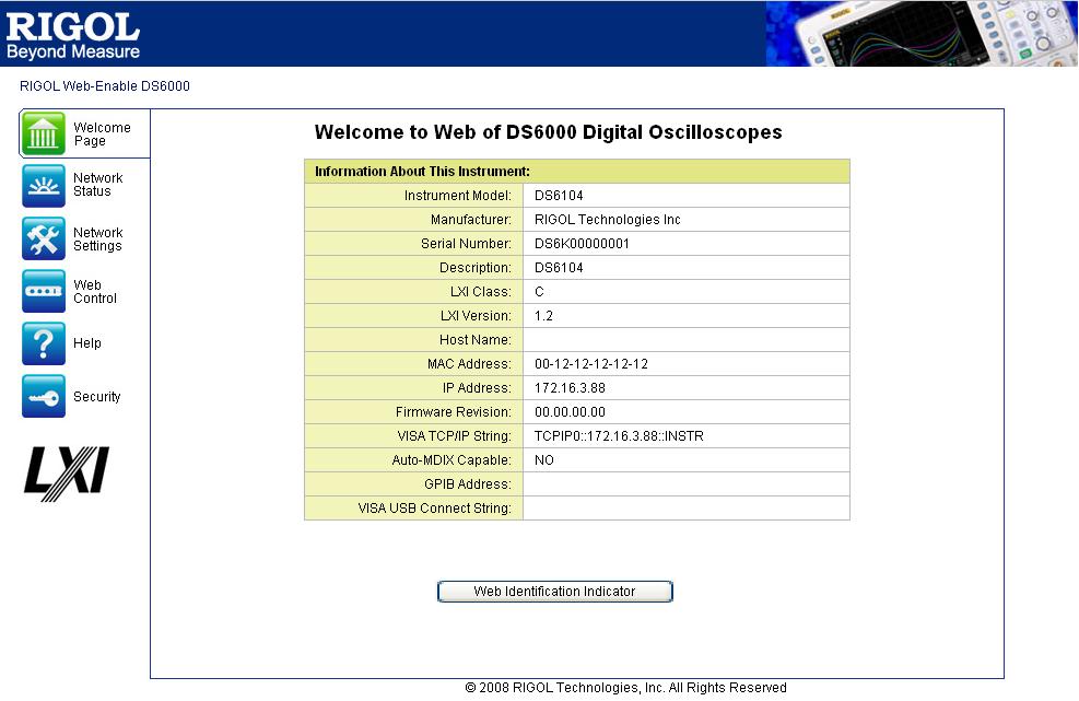
244 14-8

245 Remote Control via GPIB 1. Connect the device Use the USB to GPIB module to extend a GPIB interface for the oscilloscope. Then connect the oscilloscope to your PC using a GPIB cable. 2. Install the driver of GPIB card Install the driver of the GPIB card which has been connected to the PC correctly. 3. Set the GPIB address Set the GPIB address of the oscilloscope according to the description in System Function Setting Remote Interface Configuration To Set the GPIB Address. 4. Search device resource Start up the Ultra Sigma and click to open the panel as shown in the figure below. Click Search and the software will search the oscilloscope resources connected to the PC. The device resources will be displayed on the right side of the panel. If resources can not be found automatically: Select the GPIB card address of the PC from the combobox of GPIB:: and select the GPIB address set in the oscilloscope from the combobox of INSTR::. Click Test to check whether the GPIB communication works normally, if not, please follow the corresponding prompt messages to solve the problem. 14-9
 to select SCPI Panel Control to turn on the remote control command control panel, namely you can use this panel to send")
246 5. View device resource Click OK to return back to the main interface of Ultra Sigma. The resources found will appear under the RIGOL Online Resource directory. 6. Communication Test Right-click the resource name DS6104 (GPIB0::18::INSTR) to select SCPI Panel Control to turn on the remote control command control panel, namely you can use this panel to send commands and read data. As shown in the figure below: 14-10
RIGOL. Quick Guide. DS4000 Series Digital Oscilloscope. Sept RIGOL Technologies, Inc.
 Quick Guide DS4000 Series Digital Oscilloscope Sept. 2011 RIGOL Technologies, Inc. Guaranty and Declaration Copyright 2011 RIGOL Technologies, Inc. All Rights Reserved. Trademark Information RIGOL is
RIGOL. User s Guide. DS4000 Series Digital Oscilloscope. Feb RIGOL Technologies, Inc.
 User s Guide DS4000 Series Digital Oscilloscope Feb. 2012 RIGOL Technologies, Inc. Guaranty and Declaration Copyright 2011 RIGOL Technologies, Inc. All Rights Reserved. Trademark Information RIGOL is
RIGOL. Quick Guide. DS4000 Series Digital Oscilloscope. Aug RIGOL Technologies, Inc.
 Quick Guide DS4000 Series Digital Oscilloscope Aug. 2012 RIGOL Technologies, Inc. Guaranty and Declaration Copyright 2011 RIGOL Technologies, Inc. All Rights Reserved. Trademark Information RIGOL is a
RIGOL 快速指南 MSO4000/DS4000 系列数字示波器 2014 年 2 月. RIGOL Technologies, Inc.
 快速指南 MSO4000/DS4000 系列数字示波器 2014 年 2 月 RIGOL Technologies, Inc. Guaranty and Declaration Copyright 2013 RIGOL Technologies, Inc. All Rights Reserved. Trademark Information RIGOL is a registered trademark
RIGOL Service Guide. DS4000 Series Digital Oscilloscope. Mar RIGOL Technologies, Inc.
 Service Guide DS4000 Series Digital Oscilloscope Mar. 202 RIGOL Technologies, Inc. Guaranty and Declaration Copyright 202 RIGOL Technologies, Inc. All Rights Reserved. Trademark Information RIGOL is a
RIGOL. Quick Guide. DG2000 Series Function/Arbitrary Waveform Generator. Sept RIGOL Technologies, Inc.
 Quick Guide DG2000 Series Function/Arbitrary Waveform Generator Sept. 2010 RIGOL Technologies, Inc. Guaranty and Declaration Copyright 2010 RIGOL Technologies, Inc. All Rights Reserved. Trademark Information
User s Guide. RP7000 Series Active Probe. Dec RIGOL Technologies, Inc.
 User s Guide RP7000 Series Active Probe Dec. 2012 RIGOL Technologies, Inc. Guaranty and Declaration Copyright 2011 RIGOL Technologies, Inc. All Rights Reserved. Trademark Information RIGOL is a registered
DS1000E, DS1000D Series Digital Oscilloscope
 Quick Guide RIGOL Publication Number QGA07115-1110 May 2013 DS1000E, DS1000D Series Digital Oscilloscope DS1102E, DS1052E, DS1102D, DS1052D 2008 RIGOL Technologies, Inc. All Rights Reserved Copyright
DS1000B Series Digital Oscilloscope
 Quick Guide RIGOL Publication number QGA04116-1110 Aug. 2016 DS1000B Series Digital Oscilloscope DS1074B, DS1104B, DS1204B All Rights Reserved Copyright All Rights Reserved. RIGOL products are protected
RIGOL. Quick Guide. DG1000 Series Dual-Channel Function/Arbitrary Waveform Generator. Jul RIGOL Technologies, Inc.
 Quick Guide DG1000 Series Dual-Channel Function/Arbitrary Waveform Generator Jul. 2012 RIGOL Technologies, Inc. Guaranty and Declaration RIGOL Copyright 2011 RIGOL Technologies, Inc. All Rights Reserved.
RIGOL. User s Guide. RP5600 Passive Probe. July 2010 RIGOL Technologies, Inc.
 User s Guide RP5600 Passive Probe July 2010 RIGOL Technologies, Inc. Guaranty and Declaration Copyright 2010 RIGOL Technologies, Inc. All Rights Reserved. Trademark Information RIGOL is a registered trademark
2015 RIGOL TECHNOLOGIES, INC.
 Service Guide DG000 Series Dual-channel Function/Arbitrary Waveform Generator Oct. 205 TECHNOLOGIES, INC. Guaranty and Declaration Copyright 203 TECHNOLOGIES, INC. All Rights Reserved. Trademark Information
RIGOL. User s Guide. RP1000D Series High Voltage Differential Probe. Feb RIGOL Technologies, Inc
 User s Guide RP1000D Series High Voltage Differential Probe Feb. 2013 RIGOL Technologies, Inc Guaranty and Declaration Copyright 2012 RIGOL Technologies, Inc. All Rights Reserved. Trademark Information
Tablet Oscilloscope Safety Information
 Tablet Oscilloscope Safety Information Shenzhen Micsig Instruments Co., Ltd. General Safety Summary To use the instrument safely, please follow safety precautions carefully and obey the well-known safety
RIGOL User s Guide. MSO7000/DS7000 Series Digital Oscilloscope. Apr RIGOL TECHNOLOGIES, INC.
 RIGOL User s Guide MSO7000/DS7000 Series Digital Oscilloscope Apr. 2018 RIGOL TECHNOLOGIES, INC. RIGOL Guaranty and Declaration Copyright 2018 RIGOL TECHNOLOGIES, INC. All Rights Reserved. Trademark Information
RIGOL. User s Guide. DSA1000&DSA1000A Series Options&Accessories. Feb RIGOL Technologies, Inc.
 User s Guide DSA1000&DSA1000A Series Options&Accessories Feb. 2014 RIGOL Technologies, Inc. Guaranty and Declaration Copyright 2010 RIGOL Technologies, Inc. All Rights Reserved. Trademark Information
RIGOL Data Sheet. DS1000E, DS1000D Series Digital Oscilloscopes DS1102E, DS1052E, DS1102D, DS1052D. Product Overview. Easy to Use Design.
 RIGOL Data Sheet DS1000E, DS1000D Series Digital Oscilloscopes DS1102E, DS1052E, DS1102D, DS1052D Product Overview The DS1000E, DS1000D series instruments are economical, high-performance digital oscilloscopes.
RIGOL. User s Guide. DSA1000&DSA1000A Series Options&Accessories. May RIGOL Technologies, Inc.
 User s Guide DSA1000&DSA1000A Series Options&Accessories May 2011 RIGOL Technologies, Inc. Guaranty and Declaration Copyright 2010 RIGOL Technologies, Inc. All Rights Reserved. Trademark Information RIGOL
RIGOL. User s Guide. DSA1000&DSA1000A Series Options&Accessories. Apr RIGOL Technologies, Inc.
 User s Guide DSA1000&DSA1000A Series Options&Accessories Apr. 2015 RIGOL Technologies, Inc. Guaranty and Declaration Copyright 2010 RIGOL Technologies, Inc. All Rights Reserved. Trademark Information
RIGOL. User s Guide. DSA1000A Series Spectrum Analyzer. Jul RIGOL Technologies, Inc.
 User s Guide DSA1000A Series Spectrum Analyzer Jul. 2013 RIGOL Technologies, Inc. Guaranty and Declaration Copyright 2010 RIGOL Technologies, Inc. All Rights Reserved. Trademark Information RIGOL is a
PHV RO High Voltage Passive Probe. Instruction Manual
 PHV 1000-3-RO High Voltage Passive Probe Instruction Manual Copyright 2012 PMK GmbH All rights reserved. Information in this publication supersedes that in all previously published material. Specifications
PHV 1000-RO High Voltage Passive Probe. Instruction Manual
 PHV 1000-RO High Voltage Passive Probe Instruction Manual Copyright 2014 PMK GmbH All rights reserved. Information in this publication supersedes that in all previously published material. Specifications
RIGOL. User s Guide. DSA1000A Series Spectrum Analyzer. July RIGOL Technologies, Inc.
 User s Guide DSA1000A Series Spectrum Analyzer July 2011 RIGOL Technologies, Inc. Guaranty and Declaration Copyright 2010 RIGOL Technologies, Inc. All Rights Reserved. Trademark Information RIGOL is a
RIGOL. User s Guide. DSA1000 Series Spectrum Analyzer. Jan RIGOL Technologies, Inc.
 User s Guide DSA1000 Series Spectrum Analyzer Jan. 2010 RIGOL Technologies, Inc. Copyright 2010 RIGOL Technologies, Inc. All Rights Reserved. Trademark Information RIGOL is registered trademark of RIGOL
DS1000B Series Digital Oscilloscopes
 Product Overview DS1000B series oscilloscopes are designed with four analog channels and 1 external trigger channel, which can capture multi-channel signal simultaneously and meet industrial needs. The
DS1102E, DS1052E, DS1102D, DS1052D
 RIGOL Data Sheet DS1000E, DS1000D Series Digital Oscilloscopes DS1102E, DS1052E, DS1102D, DS1052D Product Overview DS1000E, DS1000D series are kinds of economical digital oscilloscope with high-performance.
400 MHz Passive High-Voltage Probe R&S RT-ZH
 Manual 400 MHz Passive High-Voltage Probe R&S RT-ZH11 1409.7737.02 Printed in Germany Test and Measurment Manufacturer ROHDE & SCHWARZ For comprehensive information about Rohde and Schwarz, please visit
RIGOL. User s Guide. RP1003C/RP1004C/RP1005C Current Probe. Mar RIGOL Technologies, Inc
 User s Guide RP1003C/RP1004C/RP1005C Current Probe Mar. 2013 RIGOL Technologies, Inc Guaranty and Declaration Copyright 2013 RIGOL Technologies, Inc. All Rights Reserved. Trademark Information RIGOL is
RIGOL Data Sheet. DS1000E, DS1000D Series Digital Oscilloscopes DS1102E, DS1052E, DS1102D, DS1052D. Product Overview. Applications. Easy to Use Design
 RIGOL Data Sheet DS1000E, DS1000D Series Digital Oscilloscopes DS1102E, DS1052E, DS1102D, DS1052D Product Overview DS1000E, DS1000D series are kinds of economical digital oscilloscope with high-performance.
User s Guide RIGOL. DS1000E, DS1000D Series Digital Oscilloscopes DS1102E, DS1052E, DS1102D, DS1052D. Publication number UGA July 2009
 User s Guide RIGOL Publication number UGA07111-1110 July 2009 DS1000E, DS1000D Series Digital Oscilloscopes DS1102E, DS1052E, DS1102D, DS1052D All Rights Reserved 1. All Rights Reserved 2. RIGOL products
RIGOL. User s Guide. DSA1000 Series Spectrum Analyzer. May RIGOL Technologies, Inc.
 User s Guide DSA1000 Series Spectrum Analyzer May 2012 RIGOL Technologies, Inc. Guaranty and Declaration Copyright 2010 RIGOL Technologies, Inc. All Rights Reserved. Trademark Information RIGOL is a registered
Table of Contents. 1. General Safety Requirements Safety Terms and Symbols Quick Start... 4
 General Warranty OWON warrants that the product will be free from defects in materials and workmanship for a period of 3 years from the date of purchase of the product by the original purchaser from the
SSA3000X Series Spectrum Analyzer. Quick Guide
 SSA3000X Series Spectrum Analyzer Quick Guide Copyright Information SIGLENT TECHNOLOGIES CO., LTD. All Rights Reserved. Information in this publication replaces all previously corresponding material. SIGLENT
User s Guide RIGOL. DS1000CA Series Digital Oscilloscopes DS1302CA, DS1202CA, DS1102CA, DS1062CA. Publication number DS1000CA April 2008
 User s Guide RIGOL Publication number DS1000CA-080512 April 2008 DS1000CA Series Digital Oscilloscopes DS1302CA, DS1202CA, DS1102CA, DS1062CA Copyright 1998-2008 RIGOL Technologies, Inc. All Rights Reserved
PKT 512A-RO High Impedance Passive Cable Divider
 PKT 512A-RO High Impedance Passive Cable Divider Instruction Manual Copyright 2011 PMK GmbH All rights reserved. Information in this publication supersedes that in all previously published material. Specifications
Model and
 Function Generator Model 72-14110 and 72-14111 0 Contents Function Generator... 0 Model 72-14110 and 72-14111... 0 Chapter 1 Safety Information... 3 1.1 Safety Terms and Symbols... 3 1.2 General Safety
RIGOL. User s Guide. DG4000 Series Function/Arbitrary Waveform Generator. Apr RIGOL Technologies, Inc.
 User s Guide DG4000 Series Function/Arbitrary Waveform Generator Apr. 2012 RIGOL Technologies, Inc. Guaranty and Declaration Copyright 2011 RIGOL Technologies, Inc. All Rights Reserved. Trademark Information
SDG1000X Series Function/Arbitrary Waveform Generator. Quick Start QS0201X-E01A
 SDG1000X Series Function/Arbitrary Waveform Generator Quick Start QS0201X-E01A Copyright c SIGLENT TECHNOLOGIES CO., LTD. All rights reserved. Information in this publication replaces all previous corresponding
User s Guide RIGOL. DS1000B Series Digital Oscilloscopes DS1062/4B,DS1102/4B,DS1202/4B. Publication number UGA July 2008
 User s Guide RIGOL Publication number UGA04107-1210 July 2008 DS1000B Series Digital Oscilloscopes DS1062/4B,DS1102/4B,DS1202/4B All Rights Reserved All Rights Reserved. RIGOL products are protected by
User Manual RIGOL. DS1000KCA Series Digital Oscilloscopes DS1302CA, DS1202CA, DS1102CA, DS1062CA. Publication number DS1KCA June 2007
 User Manual RIGOL Publication number DS1KCA-070712 June 2007 DS1000KCA Series Digital Oscilloscopes DS1302CA, DS1202CA, DS1102CA, DS1062CA Copyright RIGOL Technologies, Inc. 2007 All Rights Reserved Copyright
User Manual. TDS 420A, TDS 430A, TDS 460A & TDS 510A Digitizing Oscilloscopes
 User Manual TDS 420A, TDS 430A, TDS 460A & TDS 510A Digitizing Oscilloscopes 070-9701-02 Copyright Tektronix, Inc. All rights reserved. Tektronix products are covered by U.S. and foreign patents, issued
DS1052E, DS1102D, DS1052D
 RIGOL Data Sheet Product Overview DS1000E, DS1000D series are kinds of economical digital oscilloscope with high-performance. DS1000E series are designed with dual channels and 1 external trigger channel.
Quick Start RSDG2000X Function/Arbitrary Waveform Generator
 Quick Start RSDG2000X Function/Arbitrary Waveform Generator 1 2 General Safety Summary Carefully read the following safety precautions to avoid any personal injuries or damages to the instrument and any
User Manual. TDS 420A, TDS 430A, TDS 460A & TDS 510A Digitizing Oscilloscopes
 User Manual TDS 420A, TDS 430A, TDS 460A & TDS 510A Digitizing Oscilloscopes 070-9701-03 www.tektronix.com Copyright Tektronix, Inc. All rights reserved. Tektronix products are covered by U.S. and foreign
RIGOL. User s Guide. DS1000B Series Digital Oscilloscopes DS1074B,DS1104B,DS1204B. Feb RIGOL Technologies, Inc.
 User s Guide DS1000B Series Digital Oscilloscopes DS1074B,DS1104B,DS1204B Feb. 2014 Technologies, Inc. Guaranty and Declaration Copyright 2009 Technologies, Inc. All Rights Reserved. Trademark Information
RIGOL. Quick Guide. DG1000Z Series Function/Arbitrary Waveform Generator. May 2013 RIGOL Technologies, Inc.
 Quick Guide DG1000Z Series Function/Arbitrary Waveform Generator May 2013 RIGOL Technologies, Inc. Guaranty and Declaration Copyright 2013 RIGOL Technologies, Inc. All Rights Reserved. Trademark Information
RIGOL. User s Guide. DM3068 Digital Multimeter. Feb RIGOL Technologies, Inc.
 User s Guide DM3068 Digital Multimeter Feb. 2014 RIGOL Technologies, Inc. Guaranty and Declaration Copyright 2010 RIGOL Technologies, Inc. All Rights Reserved. Trademark Information RIGOL is a registered
User s Guide RIGOL. DS1000E, DS1000D Series Digital Oscilloscopes DS1102E, DS1052E, DS1102D, DS1052D. Publication number UGA July 2008
 User s Guide RIGOL Publication number UGA07107-1110 July 2008 DS1000E, DS1000D Series Digital Oscilloscopes DS1102E, DS1052E, DS1102D, DS1052D All Rights Reserved All Rights Reserved RIGOL products are
P5100A & P5150 High Voltage Probes Performance Verification and Adjustments
 x P5100A & P5150 High Voltage Probes Performance Verification and Adjustments ZZZ Technical Reference *P077053001* 077-0530-01 xx P5100A & P5150 High Voltage Probes Performance Verification and Adjustments
Operator s Manual. PP022 Passive Probe
 Operator s Manual PP022 Passive Probe 700 Chestnut Ridge Road Chestnut Ridge, NY, 10977-6499 Tel: (845) 425-2000, Fax: (845) 578 5985 teledynelecroy.com PP022 Passive Probe Instruction Manual 2017 Teledyne
MSO-5000B Mixed Storage Oscilloscope User Manual
 MSO-5000B Mixed Storage Oscilloscope User Manual Contents Contents CONTENTS... I COPYRIGHT DECLARATION... IV CHAPTER 1 SAFETY TIPS... 1 1.1 GENERAL SAFETY SUMMARY... 1 1.2 SAFETY TERMS AND SYMBOLS... 2
Electrical Safety Tester
 Electrical Safety Tester GPT-9600 Series QUICK START GUIDE GW INSTEK PART NO. 82PT-96030MA1 ISO-9001 CERTIFIED MANUFACTURER This manual contains proprietary information, which is protected by copyright.
Operator s Manual. PP016 Passive Probe
 Operator s Manual PP016 Passive Probe 2017 Teledyne LeCroy, Inc. All rights reserved. Unauthorized duplication of Teledyne LeCroy documentation materials is strictly prohibited. Customers are permitted
PEN TYPE DIGITAL MULTIMETER OPERATION MANUAL T8211D
 PEN TYPE DIGITAL MULTIMETER OPERATION MANUAL T8211D T8211D 1 1. SAFETY INFORMATION BE EXTREMELY CAREFUL IN THE USE OF THIS METER. Improper use of this device can result in electric shock or destroy of
Fluke 123/124 Industrial ScopeMeter
 Fluke 123/124 Industrial ScopeMeter Getting started GB Sep 2002 2002 Fluke Corporation, All rights reserved. Printed in The Netherlands All product names are trademarks of their respective companies. 1
Fluke 125. Getting Started. Industrial ScopeMeter
 Fluke 125 Industrial ScopeMeter Getting Started GB Dec 2006, Rev. 1, 09/2009 2006, 2009 Fluke Corporation, All rights reserved. Printed in The Netherlands All product names are trademarks of their respective
TA MHz oscilloscope probe TA MHz oscilloscope probe
 TA375 100 MHz oscilloscope probe TA386 200 MHz oscilloscope probe User's Guide X1 X10 TA386 X1/X10 Max. 600 Vp Introduction This passive high-impedance oscilloscope probe is suitable for most oscilloscopes
User s Guide RIGOL. DS1000CA Series Digital Oscilloscopes DS1302CA, DS1202CA, DS1102CA, DS1062CA. Publication number UGA Oct.
 User s Guide RIGOL Publication number UGA03106-1110 Oct. 2008 DS1000CA Series Digital Oscilloscopes DS1302CA, DS1202CA, DS1102CA, DS1062CA 2007 RIGOL Technologies, Inc. All Rights Reserved. 2007 RIGOL
User s Guide RIGOL. PA1000 Series Power Amplifier. Publication number: UGF Mar RIGOL TECHNOLOGIES, INC. All Rights Reserved.
 User s Guide Publication number: UGF01103-1110 Mar. 2017 PA1000 Series Power Amplifier 2009 TECHNOLOGIES, INC. All Rights Reserved. Copyright Information 2009 TECHNOLOGIES, INC. All Rights Reserved. products
2-channel models. 4-channel models
 2-channel models DSO1052B DSO1072B DSO1102B DSO1152B 50 MHz 70 MHz 100 MHz 150 MHz 4-channel models DSO1004A DSO1014A DSO1024A 60 MHz 100 MHz 200 MHz DSO1022A 200 MHz Segment 1 Segment 2 Segment 1000
User s Manual. Miniature Passive Probe. IM EN 3rd Edition
 User s Manual Miniature Passive Probe IM 701946-01EN 3rd Edition Thank you for purchasing the miniature passive probe. This miniature passive probe is designed for user s safety and excellent easyto-use
TETRIS 1000 High Impedance Active Probe. Instruction Manual
 TETRIS 1000 High Impedance Active Probe Instruction Manual Copyright 2015 PMK GmbH All rights reserved. Information in this publication supersedes that in all previously published material. Specifications
P5100A & P5150 High Voltage Probes Performance Verification and Adjustments
 x P5100A & P5150 High Voltage Probes Performance Verification and Adjustments ZZZ Technical Reference *P077053002* 077-0530-02 xx P5100A & P5150 High Voltage Probes Performance Verification and Adjustments
RIGOL. Service Guide. DS1000E, DS1000D Series Digital Oscilloscopes DS1102E, DS1052E, DS1102D, DS1052D. Jun 2013 RIGOL Technologies, Inc.
 Service Guide DS1000E, DS1000D Series Digital Oscilloscopes DS1102E, DS1052E, DS1102D, DS1052D Jun 2013 RIGOL Technologies, Inc. Copyright 2009 RIGOL Technologies, Inc. All Rights Reserved. Trademark
Operator s Manual. PP017 and PP018 Passive Probes
 Operator s Manual PP017 and PP018 Passive Probes 700 Chestnut Ridge Road Chestnut Ridge, NY, 10977-6499 Tel: (845) 425-2000, Fax: (845) 578 5985 teledynelecroy.com PP017 and PP018 Passive Probes Operator
DST Series B Type Digital Storage Oscilloscope User Manual
 DST Series B Type Digital Storage Oscilloscope User Manual Contents Contents Contents... i Copyright Declaration... iv Chapter 1 Safety Tips... 1 1.1 General Safety Summary... 1 1.2 Safety Terms and Symbols...
TDS3000 & TDS3000B Operator Training Kit Manual
 TDS3000 & TDS3000B Operator Training Kit Manual 071-1051-00 www.tektronix.com This product training document file is protected by Copyright Tektronix, Inc. All rights reserved. End users of this Tektronix
DSO5000P Series Digital Storage Oscilloscope User Manual. (Version 1.1)
") DSO5000P Series Digital Storage Oscilloscope User Manual (Version 1.1) Contents Contents Contents... i Chapter 1 Safety Tips... 1 1.1 General Safety Summary... 1 1.2 Safety Terms and Symbols... 2 1.3 Terms
DSO5000P Series Digital Storage Oscilloscope User Manual (Version 1.1) Contents Contents Contents... i Chapter 1 Safety Tips... 1 1.1 General Safety Summary... 1 1.2 Safety Terms and Symbols... 2 1.3 Terms
User Manual RIGOL. DS1000 Series Digital Oscilloscopes DS1000CD, DS1000C, DS1000MD, DS1000M. Publication number DS March 2006
 User Manual RIGOL Publication number DS1-061107 March 2006 DS1000 Series Digital Oscilloscopes DS1000CD, DS1000C, DS1000MD, DS1000M Copyright RIGOL Technologies, Inc. 2006 All Rights Reserved Copyright
MS8268 HANDHELD DIGITAL MULTIMETER OPERATOR S INSTRUCTION MANUAL
 MS8268 HANDHELD DIGITAL MULTIMETER OPERATOR S INSTRUCTION MANUAL Table of Contents TITLE PAGE 1. GENERAL INSTRUCTIONS 1 1.1 Precaution safety measures 1 1.1.1 Preliminary 1 1.1.2 During use 2 1.1.3 Symbols
RIGOL. User s Guide. DSA800 Series Spectrum Analyzer. Dec RIGOL Technologies, Inc.
 User s Guide DSA800 Series Spectrum Analyzer Dec. 2011 RIGOL Technologies, Inc. Guaranty and Declaration Copyright 2011 RIGOL Technologies, Inc. All Rights Reserved. Trademark Information RIGOL is a registered
User s Manual Current Probe. IM E 1st Edition. Yokogawa Electric Corporation
 User s Manual 701932 Current Probe Yokogawa Electric Corporation 1st Edition Foreword Revisions Thank you for purchasing the 701932 Current Probe. This user's manual contains useful information about the
GFL-1000 User Manual Ground Fault Locator
 GFL-Series User Manual V1.1 GFL-1000 User Manual Ground Fault Locator Contents Contents... 1 1 Declaration of Conformity... 3 2 Introduction... 3 3 Equipment Information... 3 3.1 Safety Precautions...
User Manual SDG2000X Series Function/Arbitrary Waveform Generator UM0202X-C01A
 User Manual SDG2000X Series Function/Arbitrary Waveform Generator UM0202X-C01A 2015 SIGLENT TECHNOLOGIES CO., LTD Declaration Copyright SIGLENT TECHNOLOGIES CO., LTD. All rights reserved. Without permission,
DG5000 series Waveform Generators
 DG5000 series Waveform Generators DG5000 is a multifunctional generator that combines many functions in one, including Function Generator, Arbitrary Waveform Generator, IQ Baseband /IQ IF, Frequency Hopping
Digital Clamp Meter Model: &
 Digital Clamp Meter Model: 72-7224 & 72-7226 1 SAFETY INFORMATION Please read these instructions carefully before use and retain for future reference. This meter is designed to meet IEC61010-1, 61010-2-032,
TETRIS User's Guide. High Impedance Active Probe DO177-1
 TETRIS 1500 High Impedance Active Probe User's Guide DO177-1 TETRIS 1500 Copyright 2010 Ltd. All rights reserved. Information in this publication supersedes that in all previously published material. Specifications
WaveAce 1000 and 2000 Oscilloscopes
 1000 and 2000 Oscilloscopes 40 MHz 300 MHz Key Features Sample rates up to 2 GS/s 1 Mpts/ch memory, 2 Mpts interleaved 7" color display on all models 32 automatic measurements Multi-language user interface
Agilent Technologies 3000 Series Oscilloscopes
 Agilent Technologies 3000 Series Oscilloscopes Data Sheet Full-featured oscilloscopes for the smallest budgets Features: 60 to 200 MHz bandwidths 1 GSa/s maximum sample rate Large 15-cm (5.7-in) color
MDC4500-4B Amplifier/Combiner Data Sheet & User Manual. February Rev 0.95
 MDC4500-4B Amplifier/Combiner Data Sheet & User Manual February 2016 - Rev 0.95 MDC4500-4B Amplifier IMPORTANT SAFETY and USEAGE INFORMATION Please review the following safety precautions to avoid injury
EXPERIMENT NUMBER 2 BASIC OSCILLOSCOPE OPERATIONS
 1 EXPERIMENT NUMBER 2 BASIC OSCILLOSCOPE OPERATIONS The oscilloscope is the most versatile and most important tool in this lab and is probably the best tool an electrical engineer uses. This outline guides
Single Channel. Arbitrary Waveform Generator. Quick Guide
 Single Channel Arbitrary Waveform Generator Quick Guide WWW.OWON.COM Mar. 2015 edition V1.6.3 Copyright Lilliput Company. All rights reserved. The Lilliput's products are under the protection of the patent
RIGOL. User s Guide. DS6000 Digital Oscilloscope Demo Board. July RIGOL Technologies, Inc.
 RIGOL User s Guide DS6000 Digital Oscilloscope Demo Board July 2011 RIGOL Technologies, Inc. RIGOL Guaranty and Declaration Copyright 2011 RIGOL Technologies, Inc. All Rights Reserved. Trademark Information
MS8211 DIGITAL MULTIMETER INSTRUCTION MANUAL
 MS8211 DIGITAL MULTIMETER INSTRUCTION MANUAL Ω CONTENTS CONTENTS 1. SAFETY INFORM...1 4.4 Range Transform...10 1.1 Preliminary...1 4.5 Auto Power Off...10 1.2 During use...2 4.6 Preparation For Measurement...11
Power Meter. Measurement Guide. for Anritsu RF and Microwave Handheld Instruments BTS Master Site Master Spectrum Master Cell Master
 Measurement Guide Power Meter for Anritsu RF and Microwave Handheld Instruments BTS Master Site Master Spectrum Master Cell Master Power Meter Option 29 High Accuracy Power Meter Option 19 Inline Peak
EPA152/252/502. User Manual.
 EPA152/252/502 User Manual www.audac.eu ADDITIONAL INFORMATION This manual is put together with much care, and is as complete as could be on the publication date. However, updates on the specifications,
AC/DC Clamp Meter. Owner's Manual. Model No Safety Operation Maintenance Español
 Owner's Manual AC/DC Clamp Meter Model No. 82369 CAUTION: Read, understand and follow Safety Rules and Operating Instructions in this manual before using this product. Safety Operation Maintenance Español
N2790A Differential Voltage Probe
 N2790A Differential Voltage Probe User s Guide For Safety, Regulatory, and publishing information, see the pages at the back of this book. Copyright Agilent Technologies 2009 All Rights Reserved. A Contents
USER S MANUAL PSO-120 V1.0.0
 USER S MANUAL PSO-120 V1.0.0 Content General Safety Summary... 1 Chapter 1 Getting Start... 2 1.1 System Requirement... 3 1.2 Install Software... 4 1.3 Install Driver... 7 1.4 General Features... 10 1.5
Keysight N2771B 30 kv High Voltage Probe
 Keysight N2771B 30 kv High Voltage Probe User s Guide Notices Keysight Technologies, Inc. 2012-2015 No part of this manual may be reproduced in any form or by any means (including electronic storage and
OD-610 OD-620 DIGITAL OSCILLOSCOPE
 OD-610 OD-620 DIGITAL OSCILLOSCOPE Version Date Software Version 1.1 September 2014 2.1.0.3-0 MI2010-99 Washington Street Melrose, MA 02176 Phone 781-665-1400 Toll Free 1-800-517-8431 Visit us at www.testequipmentdepot.com
DSO1000E/F Series Digital Storage Oscilloscope User Manual. (Version 1.3)
") DSO1000E/F Series Digital Storage Oscilloscope User Manual (Version 1.3) Copyright Declaration All rights reserved; no part of this document may be reproduced or transmitted in any form or by any means,
DSO1000E/F Series Digital Storage Oscilloscope User Manual (Version 1.3) Copyright Declaration All rights reserved; no part of this document may be reproduced or transmitted in any form or by any means,
Agilent Technologies 3000 Series Oscilloscopes
 Agilent Technologies 3000 Series Oscilloscopes Data Sheet Full-featured oscilloscopes for the smallest budgets Features: 60 to 200 MHz bandwidths 1 GSa/s maximum sample rate Large 15-cm (5.7-in) color
Dawson DDM190. Digital Multimeter User s Manual
 Dawson DDM190 Digital Multimeter User s Manual TABLE OF CONTENTS LIMITED WARRANTY AND LIMITATION OF LIABILITY... 3 Out of the Box... 3 Accessories.. Error! Bookmark not defined. Safety Information... 7
200Amp AC Clamp Meter + NCV Model MA250
 User's Guide 200Amp AC Clamp Meter + NCV Model MA250 Introduction Congratulations on your purchase of this Extech MA250 Clamp Meter. This meter measures AC Current, AC/DC Voltage, Resistance, Capacitance,
RP1003C/RP1004C/RP1005C
 User s Guide RP1003C/RP1004C/RP1005C Current Probe Apr. 2016 RIGOL TECHNOLOGIES, INC. Guaranty and Declaration RIGOL Copyright 2013 RIGOL TECHNOLOGIES, INC. All Rights Reserved. Trademark Information
6688 OCXO Frequency Reference 6689 Rubidium Frequency Reference. User's Manual
 6688 OCXO Frequency Reference 6689 Rubidium Frequency Reference User's Manual 6688 OCXO Frequency Reference 6689 Rubidium Frequency Reference Operators manual 2017, Pendulum Instruments / Altaria Services
TA MHz ±700 V Differential Probe User s Manual. This probe complies with IEC , IEC CAT III, Pollution Degree 2.
 TA041 25 MHz ±700 V Differential Probe User s Manual This probe complies with IEC-1010.1, IEC-1010.2-031 CAT III, Pollution Degree 2. 1. Safety terms and symbols Terms appearing in this manual: WARNING
RIGOL Data Sheet. DG3000 Series Function/Arbitrary Waveform Generator DG3121A, DG3101A, DG3061A. Product Overview. Easy to Use Design.
 RIGOL Data Sheet DG3000 Series Function/Arbitrary Waveform Generator DG3121A, DG3101A, DG3061A Product Overview DG3000 Series Function/Arbitrary Waveform Generators adopt DDS technology, which enables
LAB I. INTRODUCTION TO LAB EQUIPMENT
 1. OBJECTIVE LAB I. INTRODUCTION TO LAB EQUIPMENT In this lab you will learn how to properly operate the oscilloscope Agilent MSO6032A, the Keithley Source Measure Unit (SMU) 2430, the function generator