PEN TYPE DIGITAL MULTIMETER OPERATION MANUAL T8211D
|
|
|
- Darcy Webb
- 6 years ago
- Views:
Transcription


1 PEN TYPE DIGITAL MULTIMETER OPERATION MANUAL T8211D T8211D 1
2 1. SAFETY INFORMATION BE EXTREMELY CAREFUL IN THE USE OF THIS METER. Improper use of this device can result in electric shock or destroy of the meter. Follow all safeguards suggested in this manual and the normal safety precautions used in working with electrical circuits. Do not service this device if you are not qualified to do so. To ensure safe operation, and in order to exploit to the full the functionality of the meter, please follow the directions in this section carefully. This meter has been designed according to IEC-1010 concerning electronic measuring instruments with an overvoltage category CAT 600V and pollution 2. Follow all safety and operating instructions to ensure that the meter is used safely and is kept in good operating condition. With proper use and care, the digital meter will give you years of satisfactory service. Measurement category is for measurements performed in the building installation. (Examples are measurements on distribution boards, circuit-breakers, wiring, including cables, bus-bars, junction boxes, switches, socket-outlets in the fixed installation, and equipment for industrial use and some other equipment, for example, stationary motors with permanent connection to the fixed installation.) 1.1 PRELIMINARY When using the meter, the user must observe all normal safety rules concerning: - Protection against the dangers of electrical current. - Protection of the meter against misuse When the meter is delivered, check that it has not been damaged in transit When poor condition under harsh preservation or shipping conditions caused, inspect and confirm this meter without delay Test lead or test clip must be in good condition. Before using verify that the insulation on test lead or test clip is not damaged and/or the leads wire is not exposed Full compliance with safety standards can be guaranteed only if used with test leads supplied. If necessary, they must be replaced with the same model or same electric ratings. 1.2 DURING USE Before using, you must select the right function and range Never exceed the protection limit values indicated in specifications for each range of measurement When the meter is linked to a measurement circuit, do not touch the probe tip of the meter and test lead (or test clip) At the manual range, when the value scale to be measured is unknown beforehand, select the highest range Do not measure voltage if the voltage on the terminals exceeds 600V above earth ground Always be careful when working voltages above 60V DC or 30V AC rms, keep fingers behind the probe barrier while measuring Never connect the meter leads across a voltage source while the transform switch is in the resistance, diode or continuity mode. Doing so can damage the meter Never perform resistance, diode and continuity measurements on live circuits Before rotating the transform switch to change the function, disconnect the tip of meter and the probe of the test lead (or test clip) from the circuit under test Never use the meter under the condition of the explosive air, steam or dirt If any faults or abnormalities are observed, the meter can not be used any more and it has to be checked out Never use the meter unless the rear case is in place and fastened fully Please do not store or use meter in areas exposed to direct sunlight, high temperature, humidity or condensation. 2
 Overvoltage (Installation) category III, Pollution Degree 2 per IEC1010-1 refers to the level of Impulse Withstand Voltage protection provided.")
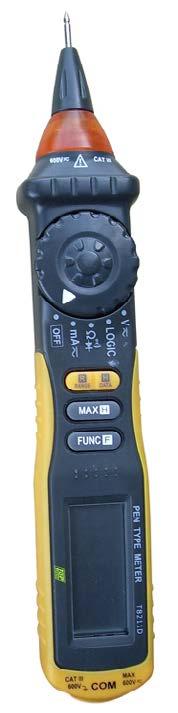
3 1.3 SYMBOLS CAT ΙΙΙ AC Important safety information, refer to the operating manual. Double insulation(protection classιι) Overvoltage (Installation) category III, Pollution Degree 2 per IEC refers to the level of Impulse Withstand Voltage protection provided. Conforms to European union directive Earth ground Alternating current DC M.H D-H AUTO Direct current AC or DC (alternating current or direct current) Diode Continuity buzzer The maximum value is being held. This indicates that the display data is being held. Auto range The battery is not sufficient for proper operation. 1.4 MAINTENANCE Please do not attempt to adjust or repair the meter by removing the rear case while voltage is being applied. A technician who fully understands danger involved should only carry out such actions Before opening the battery cover or case of the meter, always disconnect the tip of meter and the probe of the test lead (or test clip) from all tested circuits To avoid the wrong reading causing electricity attack, when the meter displays, you must change the battery Do not use abrasives or solvents on the meter, use a damp cloth and mild detergent only Always set the transform switch to the OFF position when the meter is not in use If the meter is to be stored for a long period of time, the batteries should be removed to prevent damage to the unit. 2. DESCRIPTION - This meter is a portable professional measuring instrument with handsome LCD easily reading. - Single operation of a transform switch makes measurement convenient. Overload protection and low battery indication are provided, this meter is ideal for use in the fields, workshop, school, hobby and home applications. - This meter has function of auto range and manual range. - This meter has function of auto power off. - This meter is with the functions of data hold and maximum value measure and hold. - When using, it can show ranges engineering unit enunciators measuring results. 2.1 NAMES OF COMPONENTS 1 Probe 2 Rotatable Probe Socket 3 LED Indicator 4 Protection Ring 5 Transform Switch 6 DATA-H Button 7 RANGE Button 8 MAX.H Button 9 FUNC. Button 10 Panel 11 LCD Display 12 COM Jack 3
4 2.2 COMPONENTS ELUCIDATION - indicated for information about the Button operation. Button Function DATA-H Any switch position Power-up Option Operation performed This Button is used to hold data. Disables automatic power-off feature., Ω and ma Used to transform Auto range or manual range. MAX.H Any switch position Used to measure and hold the maximum value. Button Function RANGE V FUNC. V Logic Ω ma Operation performed Switches between dc and ac voltage. Keep pressing during the Logic testing. Switches between Resistance measurement, Diode Test and Continuity check. Switches between dc and ac current. - Transform Switch This switch is used to select functions and desired ranges. - Probe / and logic test. Input terminals for V ma Ω/ - COM Jack Common terminal for measurement. - LCD Display The measuring result will be displayed. - LED Indicator At Logic test range, High level and Low level can be indicated. - Rotatable Probe Socket Rotating the probe in or out of the meter. - Protection Ring To keep the hand from the probe behind the ring. 3. SPECIFICATIONS Accuracy is specified for a period of year after calibration and at 18 to to 82 with relative humidity to 75%. 3.1 GENERAL SPECIFICATIONS Environment conditions: 600V CAT. III Pollution degree: 2 Altitude < 2000m Operating temperature: 0~40, 32 ~122 (<80% RH, <10 non-condensing) Storage temperature: -10~50, 14 ~122 (<70% RH, battery removed) Max. Voltage Between Terminals And Earth Ground: 600V DC or AC Auto ranges and manual range Display: 20mm LCD Max. Show Value: 1999 (3 1/2) Polarity Indication: - indicates negative polarity Overrange Indication: Display OL Sampling Time: approx. 0.4 second Unit showing: showing of function and electrical capacity. displayed Low Battery Indication: Fuse Protection: ma: resettable fuse Auto power off time: 15 min Power Supply: 1.5V 2 AAA battery Dimension: mm Weight: approx. 110g including battery 4
5 3.2 ELECTRICAL SPECIFICATIONS Circumstance Temperature: 23±5 Relative Humidity: < 75% DC Voltage Range Resolution Accuracy 200mV 0.1mV 2V 0.001V 20V 0.01V ±(0.7% of rdg + 2 digits) 200V 0.1V 600V 1V - Input Impedance: 10MΩ - Overload Protection: 200mV range: 250V DC or AC rms, 2V-600V ranges: DC 600V or AC 600V rms. - Max. Input Voltage: 600V DC AC Voltage Range Resolution Accuracy 200mV 0.1mV 2V 0.001V ±(0.8% of rdg + 3 digits) 20V 0.01V 200V 0.1V 600V 1V ±(1.0% of rdg + 3 digits) - Input Impedance: 10MΩ - Overload Protection: 200mV range: 250V DC or AC rms, 2V-600V ranges: DC 600V or AC 600V rms. - Frequency Range: 40 to 400Hz - Response: Average, calibrated in rms of sine wave. - Max. Input Voltage: 600V rms AC Resistance Range Resolution Accuracy 200Ω 0.1Ω ±(1.0% of rdg + 3 digits) 2kΩ 0.001kΩ 20kΩ 0.01kΩ ±(1.0% of rdg + 1 digit) 200kΩ 0.1kΩ 2MΩ 0.001MΩ 20MΩ 0.01MΩ ±(1.0% of rdg + 5 digits) - Open Circuit Voltage: 0.25V - Overload Protection: 250V DC or rms AC Continuity Range Function Built-in buzzer will sound, if resistance is lower than 50Ω. - Open circuit voltage: approx. 0.5V - Overload Protection: 250V DC or rms AC Diode Range Resolution Function 0.001V Display: read approximate forward voltage of diode - Forward DC Current: approx. 1mA - Reversed DC Voltage: approx.1.5v - Overload Protection: 250V DC or rms AC 5
6 3.2.6 DC Current Range Resolution Accuracy 20mA 0.01mA 200mA 0. 1 ma ±(1.5% of rdg + 3 digits) - Overload Protection: Resettable fuse AC Current Range Resolution Accuracy 20mA 0.01mA 200mA 0. 1 ma ±(2.0% of rdg + 3 digits) - Overload Protection: Resettable fuse. - Frequency Range: 40Hz-200Hz - Response: Average, calibrated in rms of sine wave Logic Test Range Logic Description 0V 1.5V 3.5V 5V Low "0" High "1" Green LED on Green, Red LED off Red LED on - Input Impedance: approx. 1MΩ - Overload Protection: 250V DC or rms AC 4. OPERATING INSTRUCTION 4.1 DATA HOLD If you need data hold when measuring, you can put on DATA-H button, it will hold the reading; if you put the button again, data hold is not continue. 4.2 MAXIMUM VALUE MEASURING AND HOLD At the range of voltage, you can put on MAX.H button, it will hold the maximum value; if you put the button again, the maximum value will not be held. 4.3 FUNCTION TRANSFORM Put down the "FUNC." button when measuring the voltage. Meter will be transformed between DC and AC range. Put "FUNC." button when measuring the resistance, diode and continuity, meter will transform among them. 4.4 RANGE TRANSFORM The auto range is used when measuring the voltage and resistance. Put down the "RANGE" button if the manual range is needed. Each time you put down, range will go upward; the minimum range is transformed if "RANGE" button is put down at the maximum range. If the "RANGE" button is put down more than two seconds, auto range is used again. 4.5 AUTO POWER OFF If there s no any operation within fifteen minutes after power is on, meter will auto power off with five short sounds and a long sound in a minute. After auto power off, if stir the transform switch or put down any button of FUNC., MAX.H, RANGE, meter will recover the working condition. If presses the DATA-H button when power is on, auto power off disable. In sleep mode, the auto power off function will be cancelled if presses the DATA-H button to wake the meter. 4.6 PREPARATION FOR MEASUREMENT Set the transform switch to the right range. At the manual range, when the value scale to be measured is unknown beforehand, select the highest range When measuring, at first, connect to the public (COM) testing line, then connect the probe tip of the meter to the circuit under test If the battery voltage is less than 2.4V, display will show, the battery should be changed at this time. 6


7 4.7 MEASURING DC VOLTAGE You can t input the voltage which is higher than 600V DC, it s possible to show higher voltage, but it may damage the inner circuit or cause electrical shock. Pay attention to avoid getting an electric shock when measuring high voltage Rotate the probe socket clockwise to spin out the probe from the meter Insert the black test lead or test clip in the COM jack Set the transform switch at the V range position Press the "FUNC." Button to transform to DC measurement. Auto range and manual range can be transformed by pressing the RANGE button Connect the probe tip of the meter and probe tip of the test lead (or test clip) across the power source or be loaded on the two sides under measurement You can get a reading from LCD display. The polarity of the tested terminal which the tip of the meter connection will be indicated. - At the little voltage range, the meter will show unsteady reading when test leads haven t reach the circuit, it s normal because the meter is very sensitive. When the meter touches the circuit, you can get the true reading. - At the manual range mode, when only the figure OL is displayed, it indicates over-range situation and the higher range has to be selected. - At the manual range mode, when the value scale to be measured is unknown beforehand, select the range to the highest position and set down gradually. 4.8 MEASURING AC VOLTAGE Rotate the probe socket clockwise to spin out the probe from the meter Insert the black test lead or test clip in the COM jack Set the transform switch at the V range position Press the "FUNC." button to transform to AC measurement. Auto range and manual range can be transformed by putting the RANGE button Connect the probe tip of the meter to one side of the tested circuit and probe tip of the test lead (or test clip) to the other side You can get reading from LCD display. You can t input the voltage which is higher than 600V rms AC, it s possible to show higher voltage, but it may damage the inner circuit or cause electrical shock. Pay attention to avoid getting an electric shock when measuring voltage. - At the manual range mode, when only the figure OL is displayed, it indicates over-range situation and the higher range has to be selected. - At the little voltage range, the meter will show unsteady reading when test leads haven t reach the circuit, it s normal because the meter is very sensitivity. When test leads touch the circuit, you can get the true reading. - At the manual range mode, when the value scale to be measured is unknown beforehand, select the range at the highest position and set down gradually. - Transform to the manual range when use the mv range. 7


8 4.9 MEASURING RESISTANCE Rotate the probe socket clockwise to spin out the probe from the meter Insert the black test lead or test clip in the COM jack Set the transform switch at the Ω range position. Auto range or manual range can be transformed by putting the RANGE button Connect the probe tip of the meter to one side of the tested circuit and probe tip of the test lead (or test clip) to the other side You can get reading from LCD display. When measuring in-circuit resistance, be sure the circuit under test has all power removed and that all capacitors have been discharged fully. - At the manual range mode, when only the figure OL is displayed, it indicates over-range situation and the higher range has to be selected. - For measuring resistance above 1MΩ, the meter may take a few seconds to get stable reading. - When the input is not connected, i.e. at open circuit, the figure OL will be displayed for the over-range condition TESTING DIODE Rotate the probe socket clockwise to spin out the probe from the meter Insert the black test lead or test clip in the COM jack Set the transform switch at the range position Put down the "FUNC." button transformed at test Connect the probe tip of the meter to the anode of the diode, the black test lead (or test clip) to the cathode of the diode You can get reading from LCD display. - The meter will show the approximate forward voltage drop of the diode. - If the meter and the lead connection is reversed, only figure OL will be displayed. - When the input is not connected, i.e. at open circuit, the figure OL will be displayed CONTINUITY TEST When testing the circuit continuity, be sure that the power of the circuit has been shut down and all capacitors have been discharged fully Rotate the probe socket clockwise to spin out the probe from the meter Insert the black test lead or test clip in the COM jack Set the transform switch at the range position Put down the "FUNC." button transformed at continuity test Connect the probe tip of the meter to one side of the tested circuit and probe tip of the test lead (or test clip) to the other side If continuity exists (i.e., resistance less than about 50Ω), built-in buzzer will sound. - If the input open circuit (or the circuit resistance measured is higher than 200Ω), then the figure 0L will be displayed. 8
9 4.12 MEASURING DC CURRENT To avoid damage to the Meter or injury if the fuse blows, never attempt an in-circuit current measurement where the open-circuit potential to earth is greater than 250V Rotate the probe socket clockwise to spin out the probe from the meter Insert the black test lead or test clip in the COM jack Set the transform switch at the ma range position Press the "FUNC." button to transform to DC measurement. Auto range and manual range can be transformed by pressing the RANGE button Connect the probe tip of the meter and probe tip of the test lead (or test clip) in series with the load in which the current is to be measured You can get a reading from LCD display. The polarity of the tested terminal which the tip of the meter connection will be indicated. - At the manual range mode, when only the figure OL is displayed, it indicates over-range situation and the higher range has to be selected MEASURING AC CURRENT To avoid damage to the Meter or injury if the fuse blows, never attempt an in-circuit current measurement where the open-circuit potential to earth is greater than 250V Rotate the probe socket clockwise to spin out the probe from the meter Insert the black test lead or test clip in the COM jack Set the transform switch at the ma range position Press the "FUNC." button to transform to AC measurement. Auto range and manual range can be transformed by putting the RANGE button Connect the probe tip of the meter and probe tip of the test lead (or test clip) in series with the load in which the current is to be measured You can get reading from LCD display. - At the manual range mode, when only the figure OL is displayed, it indicates over-range situation and the higher range has to be selected LOGIC TEST You can t input the voltage which is higher than 100V rms AC, it may damage the inner circuit or cause electrical shock. Pay attention to avoid getting an electric shock when testing logic level Rotate the probe socket anti-clockwise to spin the probe into the meter Insert the black test clip in the COM jack Set the transform switch at the Logic range position Connect the black test clip to the GND(-) of the circuits being measured Keep pressing the FUNC button and Touch the tip to the testing object in the circuits being measured. And observe the logic state indicated by LED light. (Red LED light expresses high level/logic 1 and green LED light expresses low level/logic 0 ) Also you can get reading and sign or from LCD display ( expresses high level/logic 1 and expresses low level/logic 0 ). - If the input open circuit (or the object s logic state is lower than 1.5V), the green LED will be lighted. - You must keep pressing the FUNC button during the logic testing. 9
10 5. MAINTENANCE 5.1 BATTERY REPLACEMENT Before attempting to open the battery cover of the meter, be sure that the probe tip of the meter and test lead (or test clip) have been disconnected from measurement circuit to avoid electric shock hazard If the sign appears on the LCD display, it indicates that the battery should be replaced Loosen the screw fixing the battery cover and remove it Replace the exhausted battery with a new one Put the battery cover as its origin. 5.2 TEST LEADS (OR TEST CLIP) REPLACEMENT Full in compliance with safety standards can be guaranteed only if used with test leads supplied. If necessary, they must be replaced with the same model or same electric ratings. Electric ratings of the test leads: 600V 10A. You must be replaced the test lead if the lead is exposed. 6. ACCESSORIES Test Lead: Electric Ratings 600V 10A Test Clip: Electric Ratings 600V 10A Battery: 1.5V, AAA Instruction Manual one piece one piece two pieces one piece CAUTION Using this appliance in an environment with a strong radiated radio-frequency electromagnetic field (approx. 3V/m), may influence its measuring accuracy. The measuring result can be strongly deviating from the actual value. 10
MS8211 DIGITAL MULTIMETER INSTRUCTION MANUAL
 MS8211 DIGITAL MULTIMETER INSTRUCTION MANUAL Ω CONTENTS CONTENTS 1. SAFETY INFORM...1 4.4 Range Transform...10 1.1 Preliminary...1 4.5 Auto Power Off...10 1.2 During use...2 4.6 Preparation For Measurement...11
MS6231 DIGITAL ENGINE ANALYZER OPERATOR S MANUAL CONTENTS CONTENTS
 CONTENTS MS6231 DIGITAL ENGINE ANALYZER OPERATOR S MANUAL CONTENTS 1. SAFETY INFORMATION 1 1.1 PRELIMINARY 2 1.2 DURING USE 3 1.3 SYMBOLS 5 1.4 MAINTENANCE 6 2. DESCRIPTION 8 2.1 NAMES OF COMPONENTS 9
DIGITAL MULTIMETER INSTRUCTION MANUAL
 DIGITAL MULTIMETER INSTRUCTION MANUAL 1 CONTENTS CONTENTS 1. SAFETY INFORMATION 1 1.1 PRELIMINARY 1 1.2 DURING USE 2 1.3 SYMBOLS 3 1.4 MAINTENANCE 4 2. DESCRIPTION 5 2.1 NAMES OF COMPONENTS 5 2.2 SWITCH,
Model DIGITAL MULTIMETER
 Model 57070 DIGITAL MULTIMETER INSTRUCTION MANUAL SAFETY INFORMATION To ensure safe operation, and in order to exploit to the full the functionality of the meter, please follow the directions in this section
AMM-1022 Digital Multimeter USER`S MANUAL
 Digital Multimeter USER`S MANUAL www.tmatlantic.com CONTENTS 1. SAFETY INFORMATION.3 2. DESCRIPTION..6 3. SPECIFICATIONS.8 4. OPERATING INSTRUCTION..11 4.1 Voltage measurement...11 4.2 Current measurement
1. SAFETY INFORMATION.1 2. DESCRIPTION SPECIFICATIONS.6 4. OPERATING INSTRUCTION Voltage measurement Current measurement 10
 CONTENTS 1. SAFETY INFORMATION.1 2. DESCRIPTION..4 3. SPECIFICATIONS.6 4. OPERATING INSTRUCTION..9 4.1 Voltage measurement...10 4.2 Current measurement 10 4.3 Resistance measurement...12 4.4 Diode test.12
MS8216 DIGITAL MULTIMETER OPERATOR S MANUAL
 MS8216 DIGITAL MULTIMETER OPERATOR S MANUAL CONTENTS 1. SAFETY INFORMATION 1 1.1 PRELIMINARY 1 1.2 DURING USE 2 1.3 SYMBOLS 4 1.4 MAINTENANCE 4 2. DESCRIPTION 5 2.1 NAMES OF COMPONENTS 5 2.2 FUNCTION AND
AC/DC DIGITAL CLAMP METER OPERATION MANUAL
 AC/DC DIGITAL CLAMP METER OPERATION MANUAL HYS005661 A0 ACCESSORIES 6. ACCESSORIES 1) Test Leads: Electric Ratings 1000V 10A 1 pair (set) 2) Operating Manual 1 copy 3) 1.5V AAA Battery 3 piece - - 55 -
DIGITAL MULTIMETER CONTENTS DIGITAL MULTIMETER CONTENTS
 CONTENTS CONTENTS CONTENTS 1. SAFETY INFORMATION...1 1.1 Preliminary...1 1.2 Dos and don ts...2 1.3 Symbols...3 1.4 Precautions...4 2. DESCRIPTION...5 2.1 Names of parts...6 2.2 Switches, buttons and input
DIGIT & POINTER MULTIMETER
 CONTENTS DIGIT & POINTER MULTIMETER OPERATOR S MANUAL 1. SAFETY INFORMATION 1 1.1 PRELIMINARY 1 1.2 DURING USE 2 1.3 SYMBOLS 3 1.4 MAINTENANCE 3 2. DESCRIPTION 4 2.1 NAMES OF COMPONENTS 4 2.2 FUNCTION
DIGITAL MULTIMETER OPERATOR S MANUAL
 DIGITAL MULTIMETER OPERATOR S MANUAL CONTENTS 1. SAFETY INFORMATION 1 1.1 PRELIMINARY 1 1.2 DURING USE 2 1.3 SYMBOLS 4 1.4 MAINTENANCE 4 2. DESCRIPTION 5 2.1 NAMES OF COMPONENTS 8 2.2 SWITCH AND BUTTONS
4.5 Auto Power Off During use Preparation For Measurement Symbols...3
 MS8211 DIGITAL MULTIMETER INSTRUCTION MANUAL Ω CONTENTS CONTENTS 1. SAFETY INFORM...1 4.4 Range Transform...10 1.1 Preliminary...1 4.5 Auto Power Off...10 1.2 During use...2 4.6 Preparation For Measurement...11
MS8223A. CAT.IIi 600 V
 Pen-type Digital Multimeter Manual MS8223A CAT.IIi 600 V CONTENTS 1. Safety Information......1 1.1 Preparing for use...1 1.2 During Use......2 1.3 Safety Symbols...3 1.4 Maintenance...4 2. Description......4
DVM98. True RMS Digital Multimeter. 1 Safety information. 1.1 Preliminary. 1.2 During use
 True RMS Digital Multimeter DVM98 1 Safety information This multimeter has been designed according to IEC - 1010 concerning electronic measuring instruments with an overvoltage category (CAT II) and pollution
OPERATOR S INSTRUCTION MANUAL
 OPERATOR S INSTRUCTION MANUAL AUTO-RANGE DUAL DISPLAY CONFORMED IEC1010 DIGITAL MULTIMETER CONTENTS PAGE SAFETY INFORMATION..... DESCRIPTION.. OPERATING INSTRUCTION.. SPECIFICATIONS.... ACCESSORIES. BATTERY
AC/DC CLAMP METER USER S MANUAL
 AC/DC CLAMP METER USER S MANUAL CONTENTS PAGE SAFETY INFORMATION SYMBOL EXPLANATION SAFETY PRECAUTIONS 1 1 2 MAINTENANCE 3 GENERAL DESCRIPTION 4 PANEL DESCRIPTION 4 OPERATING INSTRUCTIONS... 7 SPECIFICATIONS
Dawson DDM190. Digital Multimeter User s Manual
 Dawson DDM190 Digital Multimeter User s Manual TABLE OF CONTENTS LIMITED WARRANTY AND LIMITATION OF LIABILITY... 3 Out of the Box... 3 Accessories.. Error! Bookmark not defined. Safety Information... 7
DVM1190 DIGITAL MULTIMETER
 DIGITAL MULTIMETER 1. Introduction Thank you for buying the. This digital multimeter has a large LCD, a data-hold function and a backlight. The device uses a very practical safety mechanism that keeps
ProfiScale MULTI Multimeter
 1,5 V 9V 200 mv 600 V 200 ma 1/10 A ProfiScale MULTI Multimeter en Operating instructions BURG-WÄCHTER KG Altenhofer Weg 15 58300 Wetter Germany Introduction Want the reassurance of knowing whether current
1. SAFETY 1.1. SAFETY INFORMATION 1.2. SAFETY SYMBOLS
 To all residents of the European Union Important environmental information about this product This symbol on the device or the package indicates that disposal of the device after its lifecycle could harm
OPERATOR S INSTRUCTION MANUAL DIGITAL MULTIMETER
 OPERATOR S INSTRUCTION MANUAL DIGITAL MULTIMETER SAFETY INFORMATION This multimeter has been designed according to IEC 1010 concerning electronic measuring instruments with an overvoltage category (CATⅡ)
DIGITAL CLAMP METER Use s Manual
 MS2026 MS2026R DIGITAL CLAMP METER Use s Manual MS2026 FUNC. RANGE MAX/MIN Hz/% HOLD AC CLAMP METER Auto Range AUTO DC AC MAX MIN REL μnf %Hz kmω mva CAT III 600 V CONTENTS 1. Safety Information...1 1.1
HANDHELD DIGITAL MULTIMETER OPERATOR S INSTRUCTION MANUAL
 HANDHELD DIGITAL MULTIMETER OPERATOR S INSTRUCTION MANUAL GENERAL INSTRUCTIONS This instrument complies with IEC 1010-1 (61010-1@IEC: 2001), CAT. II 1000V and CAT. III 600V overvoltage standards. See Specifications.
KMD-S04 Multímetro de bolsillo
 www.grupotemper.com KMD-S04 Multímetro de bolsillo Table of Contents Title Page Overview ~~~~~~~~~~~~~~~~~~~~~~~~~~~~~~~~~~~~~~~~~~ 3 Unpacking Inspection ~~~~~~~~~~~~~~~~~~~~~~~~~~~~~~~~~ 4 Safety Information
EM420A/420B DIGITAL MULTIMETER OWNERS MANUAL Read this owners manual thoroughly before use
 http://www.all-sun.com EM420A/420B DIGITAL MULTIMETER OWNERS MANUAL V Read this owners manual thoroughly before use WARRANTY This instrument is warranted to be free from defects in material and workmanship
Digital Multimeter, Pen Type
 MODEL: D03127 Digital Multimeter, Pen Type 1 CONTENTS Page Number Description 3 Important Safety Information 3 Electrical Symbols 4 Overview 4 Measurement Operation 5 AC & DC Voltage Measurement 5 AC &
DIGITAL MULTIMETER OPERATOR'S INSTRUCTION MANUAL HOLD 10A COM LIGHT MS8265 ON/OFF. 200M KHz 2K 20K μ μ μ n.
 MS8265 DIGITAL MULTIMETER OPERATOR'S INSTRUCTION MANUAL HOLD ON/OFF LIGHT 1000V CAT II 600V CAT III MS8265 200K 2M 20M 20K 200M KHz 2K 20 200 2 20 200μ 200 20μ 750 2μ 1000 200n F 20n 10A 2m 200m 10 10
Sales: Technical: Fax:
 DATA SHEET Order code Manufacturer code Description 85-0733 n/a n/a The enclosed information is believed to be correct, Information may change without notice due to product improvement. Users should ensure
1.General instructions Specifications Description...7
 USER S Manual CONTENTS 1.General instructions...1 1.1 Precautions safety measures...1 1.1.1 Preliminary...1 1.1.2 During use...2 1.1.3 Symbols...4 1.1.4 Instructions...5 1.2 Protection mechanisms...6 2.
Contents 1. General instructions. 1.1 Precautions safety measures Protection mechanisms. 2. Description. 2.1 Instrument Familiarization. 2.
 Contents 1. General instructions. 1.1 Precautions safety measures... 1.2 Protection mechanisms. 2. Description. 2.1 Instrument Familiarization. 2.2 LCD Display 2.3 Keypad. 3. Function description. 3.1
INSTRUCTION MANUAL DIGITAL MULTIMETER
 INSTRUCTION MANUAL DIGITAL MULTIMETER 600 OFF 600 20 2m 2 20m m m 2M 10A k 20k 2k O C NPN PNP hfe E B C E 10A DC 10A MAX UNFUSED MAX 600V COM V ma ma MAX FUSED CAT II 600V Thanks for buying our products,
MS8250A/B OPERATION MANUAL MS8250A. Hz% FUNC REL RANGE REL HOLD OFF 10A. Hz% A NCV. Hz% COM. A ma 10A FUSED 600V CAT IV.
 MS8250A/B DIGITAL MULTIMETER OPERATION MANUAL AUTO DC AC REL hfe PCLINK % C F kmωkz nµmfav MS8250A DIGITAL MULTIMETER Auto Power Off RANGE REL HOLD FUNC NCV A ma OFF 10A A ma 10A FUSED 600V CAT IV COM
Model : OPERATING MANUAL Table of Contents (1)
") Table of Contents (1) Title Overview Unpacking Inspection Safety Information Rules For Safe Operation International Electrical Symbols The Meter Structure Functional Buttons Measurement Operation A. DC
Table of Contents (1) Title Overview Unpacking Inspection Safety Information Rules For Safe Operation International Electrical Symbols The Meter Structure Functional Buttons Measurement Operation A. DC
User Manual Digital Clamp Multimeter. model no.: MSR-C600
 User Manual Digital Clamp Multimeter model no.: MSR-C600 Overview This Operating Manual covers information on safety and cautions. Please read the relevant information carefully and observe all the Warnings
MS2030 CAT III 600 V A V AUTO RS232
 MS2030 AC Digital Clamp Meter User s Manual CAT III 600 V AUTO RS232 A V CONTENTS 1.Introduction...1 2.Safety Information...1 2.1 Precautions...1 2.2 Safety Symbols...3 3. Description...4 3.1 Front Panel...4
DMM8900 SERIES USERS MANUAL
 DMM8900 SERIES USERS MANUAL WARRANTY This instrument is warranted to be free from defects in material and workmanship for a period of one year. Any instrument found defective within one year from the delivery
DDM350 Pen-Type Digital Multimeter User s Manual
 DDM350 Pen-Type Digital Multimeter User s Manual CONTENTS LIMITED WARRANTY AND LIMITATION OF LIABILITY....1 Out of the Box...1 Accessories......2 Safety Information...2 Safety Symbols...3 Certification......4
Thank you again for choosing AstroAI, if you have any questions or concerns regarding your product, please contact us at
 ASTROAI USER MANUAL DT132A 4000 Count Auto-Ranging Multimeter Thank you for purchasing the AstroAI DT132A 4000 Count Auto-Ranging Multimeter. It is a 3 ¾ digit, 3999 counts, auto-ranging digital multimeter.
UT207A/208A/209A Operating Manual. Table of Contents
 Table of Contents Title Overview Unpacking Inspection Safety Information Rules for Safe Operation International Electrical Symbols The Meter Structure Display Symbols Functional Buttons The Effectiveness
MS8268 HANDHELD DIGITAL MULTIMETER OPERATOR S INSTRUCTION MANUAL
 MS8268 HANDHELD DIGITAL MULTIMETER OPERATOR S INSTRUCTION MANUAL Table of Contents TITLE PAGE 1. GENERAL INSTRUCTIONS 1 1.1 Precaution safety measures 1 1.1.1 Preliminary 1 1.1.2 During use 2 1.1.3 Symbols
Multifunction Digital
 MS2009A Multifunction Digital Clamp Meter User Manual 200/600 OFF 2/20 NCV SEL MAX V RAN HOLD OFF MS2009A AC CLAMP METER AUTO MAX C F kmω μmva CONTENTS Safety requirements...1 Safety signs...1 Notes...1
Table of Contents Title Page
 Table of Contents Title Page Overview Unpacking Inspection Safety Information Rules For Safe Operation International Electrical Symbols The Meter Structure Rotary Switch Functional Buttons Display Symbols
MS8250D DUAL DISPLAY DIGITAL MULTIMETER User s Manual
 DUAL DISPLAY DIGITAL MULTIMETER User s Manual MS8250D 1. Safety Information Warning Use caution and follow all safety guidelines to prevent electric shock or damage to the meter. Please ready carefully
Dawson DDM181. Pocket-Size Autorange Digital Meter User s Manual
 Dawson DDM181 Pocket-Size Autorange Digital Meter User s Manual 1 Table of Contents LIMITED WARRANTY AND LIMITATION OF LIABILITY... 3 Out of the Box... 3 Accessories... 4 Important Safety Information...
Digital Multimeter with Backlight
 MODEL: D03126 Digital Multimeter with Backlight 1 CONTENTS Page Number Description 3 Important Safety Information 3 What s Included? 4 Overview 4 Front Panel Description 5 General Specification 5 DC Voltage
Model UT10A: OPERATING MANUAL Table of Contents (1)
") Table of Contents (1) Table of Contents Title Page Overview Unpacking Inspection Safety Information Rules For Safe Operation International Electrical Symbols The Meter Structure Functional Buttons Measurement
Table of Contents (1) Table of Contents Title Page Overview Unpacking Inspection Safety Information Rules For Safe Operation International Electrical Symbols The Meter Structure Functional Buttons Measurement
MS2109A AC/DC Clamp Meter. User Manual. Contents
 MS2109A AC/DC Clamp Meter User Manual Contents 1. Safety information 1 1.1 Preparation 1 1.2 Usage 1 1.3 Signs and Labels 2 1.4 Maintenance 2 2. Description 2 2.1 Part name 3 2.2 Switch and button description
ETHOS 5030 TRUE-RMS DIGITAL MULTIMETER OPERATION MANUAL
 ETHOS 5030 TRUE-RMS DIGITAL MULTIMETER OPERATION MANUAL 1 1. SAFETY INFORMATION SAFETY SYMBOLS Warning! Dangerous Voltage (Risk of electric shock). Caution! Refer to the user s manual before using this
Model UT20B: OPERATING MANUAL Table of Contents (1)
") Table of Contents (1) Title Overview Unpacking Inspection Safety Information Rules For Safe Operation International Electrical Symbols Rotary Switch Display Symbols Measurement Operation A. AC Voltage
Table of Contents (1) Title Overview Unpacking Inspection Safety Information Rules For Safe Operation International Electrical Symbols Rotary Switch Display Symbols Measurement Operation A. AC Voltage
Digital Clamp Meter. User Manual
 Digital Clamp Meter User Manual CM240 WWW.OWON.COM.CN Mar. 2016 edition V1.2 Copyright LILLIPUT Company. All rights reserved. The LILLIPUT's products are under the protection of the patent rights, including
User Manual Digital Multimeter
 User Manual Digital Multimeter model no.: MSR-R500 Questions or Concerns? support@etekcity.com visit etekcity.com for more products Safe and Proper Usage Thank you for purchasing the Etekcity MSR-R500
Digital Clamp Meter Model: &
 Digital Clamp Meter Model: 72-7224 & 72-7226 1 SAFETY INFORMATION Please read these instructions carefully before use and retain for future reference. This meter is designed to meet IEC61010-1, 61010-2-032,
3B SCIENTIFIC PHYSICS
 3B SCIENTIFIC PHYSICS Digital Multimeter E 1018832 Instruction sheet 12/16 SD/UD 1 probe 1a Finger guards 2 Measurement socket 10 A for current measurement in 10-A (positive) 3 Measurement socket COM (negative)
Model UT201/202: OPERATING MANUAL. Table of Contents
 Table of Contents Title Overview Unpacking Inspection Safety Information Rules For Safe Operation International Electrical Symbols The Meter Structure Rotary Switch Functional Buttons The Effectiveness
INSTRUCTION MANUAL. Model Autoranging DMM ProbeMeter TM. Measures voltage, resistance, frequency, capacitance, temperature, and duty cycle.
 INSTRUCTION MANUAL Model 403380 Autoranging DMM ProbeMeter TM Measures voltage, resistance, frequency, capacitance, temperature, and duty cycle. Back lit LCD with Autorange and full function displays Audible
IDEAL INDUSTRIES, INC. TECHNICAL MANUAL MODEL:
 IDEAL INDUSTRIES, INC. TECHNICAL MANUAL MODEL: 61-352 The Service Information provides the following information: Precautions and safety information Specifications Basic maintenance (cleaning, replacing
DVM645BI BENCH MULTIMETER TAFELMULTIMETER MULTIMETRE DE TABLE BANCO MULTÍMETRO TISCHMULTIMETER. User Manual. Gebruikershandleiding
 BENCH MULTIMETER TAFELMULTIMETER MULTIMETRE DE TABLE BANCO MULTÍMETRO TISCHMULTIMETER User Manual Gebruikershandleiding Manuel d'utilisation Gebrauchsanleitung Introduction BENCH MULTIMETER This manual
OPERATOR S INSTRUCTION MANUAL
 2 OPERATOR S INSTRUCTION MANUAL CLAMP METER HOLD 20 A 200 A 2 A 600 600 LIGHT ON/OFF Digital Clamp Meter 2 20 200 A khz COM CAT.II MAX 600 CONTENTS 1. General instruction.....1 2. Description...1 2.1 Precautions
DCM730. Digital Clamp Meter User s Manual
 DCM730 Digital Clamp Meter User s Manual Table of Contents LIMITED WARRANTY AND LIMITATION OF LIABILITY...1 Out of the Box...1 Safety Information...2 INTRODUCTION...4 Components and Buttons...6 Names of
NOTE: Fully read and understand this manual before using this Digital Multimeter.
 ASTROAI USER MANUAL AUTO RANGING DIGITAL CLAMP METER Thank you for purchasing the Auto Ranging Digital Clamp Meter from AstroAI. The AstroAI Auto Ranging Digital Clamp Meter is designed to be safely and
DIGITAL MULTIMETER AUTORANGING
 MODEL: D03124 DIGITAL MULTIMETER AUTORANGING 1 CONTENTS Page Number Details 2 Introduction 2 What s Included 3 Important Safety Information 3 Symbol Guide 4 Overview 5 Buttons 5 Display Indicators 6 General
MS8250D DUAL DISPLAY DIGITAL MULTIMETER User s Manual
 DUAL DISPLAY DIGITAL MULTIMETER User s Manual MS8250D Introduction MS8250D is a stable, safe, reliable compact digital handheld 6600 count, True RMS, auto-ranging multimeter. This meter can measure AC/DC
Model ST Instruction Manual. True RMS Autoranging Digital Multimeter. reedinstruments. www. com
 Model ST-9933 True RMS Autoranging Digital Multimeter Instruction Manual reedinstruments com Table of Contents Safety... 3 Features... 4 Specifications...4-8 Technical...4-5 Accuracy...5-8 Display Description...
USER MANUAL 600A AC Clamp Meter + NCV Model MA610
 USER MANUAL 600A AC Clamp Meter + NCV Model MA610 Additional User Manual Translations available at www.extech.com Introduction Thank you for selecting the Extech MA610 Clamp Meter. This meter measures
Table of Contents GDM-356. Page
 Table of Contents Title Overview Unpacking Inspection Safety Information Rules For Safe Operation International Electrical Symbols The multimeter Structure Functional Buttons Display Symbols Measurement
MODEL: D03128 CLAMP METER
 MODEL: D03128 CLAMP METER 1 CONTENTS Page Number Details 3 Important Safety Information 3 Features 4 Product Overview 5 Switches, Buttons & Input Jacks 5 LCD 6 Specifications 6 Electrical Specifications
Pen Multimeter. Model
 Pen Multimeter Model 381626 CAUTION: Read, understand and follow all Safety Rules and Operating Instructions in this manual before using this product. This instrument is a 3200 count pen style digital
CONTENTS MS2033A. 1.Introduction Safety Information...01
 MS2033A AC Digital Clamp Meter User s Manual CAT III 600 V CONTENTS 1.Introduction...01 2.Safety Information...01 2.1 Precautions...02 2.2 Safety Symbols...03 3. Description...04 3.1 Front Panel...04 3.2
The Meter Structure The Figure 2-1 shows the Meter structure.
 P/N:110401104496X The Meter Structure The Figure 2-1 shows the Meter structure. 1. USB Terminals 2. LCD Display 3. Functional Buttons 4. Rotary Switch 5. Power adaptor Input Terminals 6. 10A Input Terminal
DIGITAL DUAL DISPLAY AC/DC CLAMP METER MODEL-860A OPERATION MANUAL
 DIGITAL DUAL DISPLAY AC/DC CLAMP METER MODEL-860A OPERATION MANUAL DIGITAL DUAL DISPLAY AC/DC CLAMP METER MODEL-860A TABLE OF CONTENTS TITLE PAGE Safety Information Safety Symbols... 1 Meter Description...
DM-45 Digital Multimeter
 INSTRUCTION MANUAL DM-45 Digital Multimeter Read and understand all of the instructions and safety information in this manual before operating or servicing this tool. Description The Greenlee DM-45 Digital
Internetowy sklep elektroniczny. Kontakt. Tel Tel. Kom Fax
 DOKUMENT TEN JEST PRZEZNACZONY DLA KLIENTÓW FIRMY Internetowy sklep elektroniczny WWW.DIOLUT.PL Kontakt Tel. +48 0334866616 Tel. Kom. +48 0888139522 Fax. +48 0334866617 e-mail diolut@diolut.pl Table of
RAGU 81D DIGITAL MULTIMETER OPERATION MANUAL
 RAGU 81D DIGITAL MULTIMETER OPERATION MANUAL Contents I. General...- 1 - Ⅱ. Open-package Inspection...- 2 - III. Safety Considerations... - 3 - IV.Instrument Panel & Button Function Description...- 9 -
Pen-type DIGITAL MULTITESTER
 BST-MT267 Pen-type DIGITAL MULTITESTER INSTRUCTION MANUAL Index 1. Introduction... 2. Safety Notes... 3. Features... 4. Specifications... 5. General... 6. Instrument Layout... 7. Measurement... 8. Maintenance...
OPERATOR S INSTRUCTION MANUAL M-2625 AUTO RANGING DIGITAL MULTIMETER
 OPERATOR S INSTRUCTION MANUAL M-2625 AUTO RANGING DIGITAL MULTIMETER with Temperature Probe Copyright 2007 Elenco Electronics, Inc. Contents 1. Safety Information 3,4 2. Safety Symbols 5 3. Front Plate
AX-C Introduction. 2. Safety Information
 AX-C708 1. Introduction Read Safety Information before using the meter. ProcessMeter ( referred to as the meter )is a handheld, battery-operated tool for measuring electrical parameters. It has all the
Model UT50D: OPERATING MANUAL. Table of Contents
 Table of Contents Overview Unpacking Inspection Safety Information Rules For Safe Operation International Electrical Symbols The Meter Structure Functional Buttons Display Symbols Measurement Operation
200Amp AC Clamp Meter + NCV Model MA250
 User's Guide 200Amp AC Clamp Meter + NCV Model MA250 Introduction Congratulations on your purchase of this Extech MA250 Clamp Meter. This meter measures AC Current, AC/DC Voltage, Resistance, Capacitance,
OWNER S MANUAL HH0308C. AUTO-RANGING DC/True RMS AC DIGITAL MULTIMETER
 OWNER S MANUAL HH0308C AUTO-RANGING DC/True RMS AC DIGITAL MULTIMETER IMPORTANT! Read and understand this manual before using the tester. Failure to understand and comply with safety rules and operating
AUTO-SCAN Pen R/C/D Meter for SMD AX-507B USER S MANUAL
 AUTO-SCAN Pen R/C/D Meter for SMD AX-507B USER S MANUAL 1. GENERAL INSTRUCTIONS This auto scan pen R/C/D meter fir SMD could fast precise measure small chip components. To get the best service from this
User Guide. Digital AC/DC Clamp Meter Model 38394
 User Guide Digital AC/DC Clamp Meter Model 38394 Introduction Congratulations on your purchase of Extech s 38394 AC/DC Clamp Meter. This clamp meter measures AC/DC Current to 600A, DC/AC Voltage, Resistance,
Instruction Manual ICM 3091N Digital AC Clampmeter EN FR IT DE ES
 Instruction Manual ICM 3091N Digital AC Clampmeter EN FR IT DE ES TABLE OF CONTENTS / EN TITLE TABLE OF CONTENTS PAGE 1. SAFETY INFORMATION... 1 2. TECHNICAL SPECIFICATIONS... 2 3. PARTS & CONTROLS...
770E DIGITAL MULTIMETER OPERATOR S MANUAL
 770E DIGITAL MULTIMETER OPERATOR S MANUAL TABLE OF CONTENTS 1.Overview... 1 2.Panel Layout...1/2 3. Safety information... 2 4. Specical cautions for operation.... 2 5.General specifications...2/3 6.Testing
DIGITAL MULTIMETER OPERATION MANUAL
 OPERATION MANUAL CONTENTS 4.10 MEASURING DC VOLTAGE 29 4.11 MEASURING AC VOLTAGE 30 4.12 MEASURING FREQUENCY 31 4.13 MEASURING DUTY 32 4.14 MEASURING DC CURRENT 32 4.15 MEASURING AC CURRENT 33 4.16 MEASURING
CONTENTS. SAFETY PRECAUTIONS: Before use, read the following safety precautions
 CONTENTS [1] SAFETY PRECAUTIONS: Before use, read the following safety precautions 2 [2] APPLICATION AND FEATURES 5 [3] NAME OF COMPONENT UNITS 6 [4] DESCRIPTION OF FUNCTIONS 8 [5] MEASUREMENT PROCEDURE
User s Guide. Digital AC/DC Clamp Meter Model 38394
 User s Guide Digital AC/DC Clamp Meter Model 38394 Introduction Congratulations on your purchase of Extech s 38394 AC/DC Clamp Meter. This clamp meter measures AC/DC Current to 600A, DC/AC Voltage, Resistance,
USER'S MANUAL ACDC-100 TRMS ACDC-100. Versatile AC/DC Clamp-on Multimeter Series
 99 Washington Street Melrose, MA 02176 Fax 781-665-0780 TestEquipmentDepot.com USER'S MANUAL ACDC-100 TRMS ACDC-100 Versatile AC/DC Clamp-on Multimeter Series 1 1) SAFETY This manual contains information
AM-510 Commercial / Residential Multimeter. AM-510-EUR Digital Multimeter. Users Manual
 AM-510 Commercial / Residential Multimeter AM-510-EUR Digital Multimeter Users Manual AM-510 Commercial / Residential Multimeter AM-510-EUR Digital Multimeter English Users Manual Limited Warranty and
MT /6 Smart Digital Clamp Meter. User s Manual 1 st Edition, 2016 Copyright by Prokit s Industries Co., Ltd.
 MT-3110 3 5/6 Smart Digital Clamp Meter User s Manual 1 st Edition, 2016 Copyright by Prokit s Industries Co., Ltd. 1.Safety Information Warnings Special attention shall be paid when using the meter, improper
Item ref: UK MTM01 DIGITAL MULTITESTER. User Manual
 Item ref: 600.100UK MTM01 DIGITAL MULTITESTER User Manual Please read this manual thoroughly and ensure all contents are fully understood before using the apparatus. Warning To avoid possible electric
USER'S MANUAL DMR-6700
 USER'S MANUAL Multimeter True RMS DMR-6700 CIRCUIT-TEST ELECTRONICS www.circuittest.com Introduction This meter measures AC/DC Voltage, AC/DC Current, Resistance, Capacitance, Frequency (electrical & electronic),
User Manual Digital Multimeter. model no.: MSR-U1000
 User Manual Digital Multimeter model no.: MSR-U1000 This Operating Manual covers information on safety and cautions. Please read the relevant information carefully and observe all the Warnings and Notes
MM V 10A ENGLISH. INSTRUCTION MANUAL Auto-Ranging DATA HOLD AUDIBLE CONTINUITY MIN / MAX TEMPERATURE DIODE TEST CAPACITANCE
 INSTRUCTION MANUAL Auto-Ranging Digital Multimeter MM400 DATA HOLD AUDIBLE CONTINUITY MIN / MAX TEMPERATURE DIODE TEST CAPACITANCE 600V 10A 40MΩ 2 GENERAL SPECIFICATIONS Klein Tools MM400 is an auto-ranging
Dawson DDM230C. True RMS Multimeter with Bar Graph Display User s Manual
 Dawson DDM230C True RMS Multimeter with Bar Graph Display User s Manual Table of Contents LIMITED WARRANTY AND LIMITATION OF LIABILITY... 3 Out of the Box... 3 Accessories... 4 Safety Information... 4
DIGITAL MULTIMETER OPERATING INSTRUCTIONS MODEL CDM-35. Part No
 DIGITAL MULTIMETER MODEL CDM-35 Part No.4500055 OPERATING INSTRUCTIONS 0304 The Meter may be hung on a wall, or supported as shown, depending upon which support is used. The probes may be located as shown,
Mini Clamp Meter Model:
 Mini Clamp Meter Model: 72-2985 1 CONTENTS Page Number Details 2 What s Included 3 Important Safety Information 3 Technical Specification 4 Product Overview 5 LCD Overview 6 Operation - AC/DC Voltage Measurement
Pocket Size Digital Multimeter Models: and
 Pocket Size Digital Multimeter Models: 72-8150 and 72-8155 1 IMPORTANT SAFETY INFORMATION Please read these instructions carefully before use and retain for future reference. Please operate according to
Tablet Oscilloscope Safety Information
 Tablet Oscilloscope Safety Information Shenzhen Micsig Instruments Co., Ltd. General Safety Summary To use the instrument safely, please follow safety precautions carefully and obey the well-known safety
400Amp True RMS AC Clamp Meter + NCV
 User Guide 400Amp True RMS AC Clamp Meter + NCV Model MA410T Introduction Thank you for selecting the Extech MA410 Clamp Meter. This meter measures AC Current, AC/DC Voltage, Resistance, Capacitance, Frequency,
312, 316, 318. Clamp Meter. Users Manual
 312, 316, 318 Clamp Meter Users Manual PN 1989445 July 2002 Rev.2, 2/06 2002, 2006 Fluke Corporation. All rights reserved. Printed in China. All product names are trademarks of their respective companies.