Product Catalogue Millimeter Wave, Sub-Millimeter Wave / THz Solutions
|
|
|
- Reynard Cox
- 5 years ago
- Views:
Transcription


1 Telephone: +33 (0) Fax: +33 (0)
2 TABLE OF CONYENTS Frequency Sources - Multiplier Chain... 3 Frequency Sources VCO / PLO Based... 4 Portable Millimeter Wave / THz Transmitter & Receivers... 5 VNA Frequency Extenders TR-R and TR-TR Sets... 6 Millimeter Wave / THz Down Converters... 8 Millimeter Wave Noise Measurement Converters... 9 Solid State Noise Source Amplifiers - Low Noise Amplifiers Amplifiers - Power Amplifiers Mixers - Fundamental Balanced Mixers Mixers - Low Noise Sub Harmonic Mixers Mixers - Full Band Waveguide Harmonic Mixers Attenuators - Full Band Waveguide Variable & Fixed Detectors - Full Waveguide Band Isolators - Full Waveguide Band Couplers - Full Waveguide Band Probes Millimeter / THz Near Field Probes Antennas - Waveguide Pyramidal Horn Antennas - Waveguide Diagonal Horn Antennas Antennas - Lens Horn Antennas Antennas - Waveguide Corrugated Horn Low Pass Filters Band Pass & Band Stop Filters High Pass Filters Precision Waveguide Straight Sections Precision Waveguide Bends & Twists Precision Waveguide Short & Terminations Precision Waveguide Transitions Cryogenic Primary Noise Standard
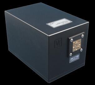
 Compact, fully screened enclosure with")
 50 70 60 90 67 87 68 78 90 140 210 224 220 330 325 500 Waveguide WR 12 WR 12 WR 12 WR 04 WR 2.2 Input Frequency (GHz) 8.33 12.50 8.33 11.67 10.00 15.00 11.16 14.50 11.33 13.")
 +3, +6 +15 typical +3, +5 +13 typical +20 typical +3, +6 +13, +16 +6 typical +6 min, +10 typical +4 typical +10, +12-7, -5-10, -8 1. RF input power: +7 to +10 dbm 2.")
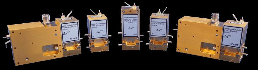
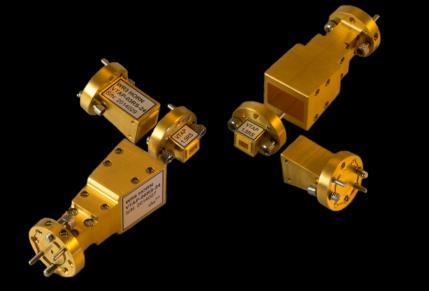
3 Frequency Sources - Multiplier Chain VTXFA-10FBH Output Power, GHz Plug n Play: just add DC power and RF microwave input Coverage: GHz Standard waveguide full-band & narrow-band Ideal signal generator or frequency extender High output power Standard or custom input power levels Flat frequency response Optional output isolators (up to 220 GHz) Compact, fully screened enclosure with integral heat sink VTXFA-15FB VTXFA-15HA VTXFA-12FB VTXFA-12HA VTXFA-12HB VTXFA-10FB VTXFA-10FBH VTXFA-08FB VTXFA-06FB VTXFA-05FB VTXFA-04H VTXFA-03FB VTXFA-2.2FB Output Frequency (GHz) Waveguide WR 12 WR 12 WR 12 WR 04 WR 2.2 Input Frequency (GHz) Output Power (dbm) +3, typical +3, typical +20 typical +3, , typical +6 min, +10 typical +4 typical +10, +12-7, -5-10, RF input power: +7 to +10 dbm 2. Harmonic and spurious: < 20 dbc typical 3. DC: +7 to +9 VDC, < 1 A typical 4. Input connector: SMA (F) or K (F) 5. How to make a request: specify above, or input and output frequencies, output power desired, waveguide size, and isolator if required; to: sales@vivatech.biz 3
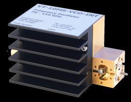
 VCO as standard, other fundamental sources eg.")
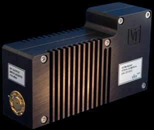
4 Frequency Sources VCO / PLO Based GHz VCO Output Power Typical Performance Frequency coverage: 50 - > 670 GHz Analog/Digital tuned VCO driven multiplier chains State of art power output Optional output isolator (up to 220 GHz) VCO as standard, other fundamental sources eg. YIG, Synthesizer can be chosen to suit application Fully integrated miniature versions Frequency (GHz) Waveguide Power Output (dbm) VTVCO-15FB VTVCO-10FB VTVCO-06FB VTVCO-05FB VTVCO-03FB VTVCO-1.5NB WR to to to to to to -15 Frequency Accuracy % -1 +/ / / / / /- 5 ppm Power Flatness (db) +/- 1 +/- 1 +/- 1 +/- 2 +/- 2 +/ Based on a multiplied internal free running VCO oscillator, integrated with the source 2. DC power required is V, 1-2 A depending on model 3. VCO tuning voltage is typically in the range 0-16 V DC 4. Digitally tuned versions are available to specification, based on an integrated or external synthesizer 5. Sizes from 45 x 50 x 20 mm, excluding heat sink 6. How to make a request: specify waveguide size, frequency range, frequency accuracy, output power and flatness, to: sales@vivatech.biz 4

5 Portable Millimeter Wave / THz Transmitter & Receivers Extend portable VNA s to mm-wave and THz Coverage GHz in custom bands Extends VNA s without LO/IF access Synchronous frequency and sweep operation Fully compatible with Keysight Fieldfox portable VNA and various Anritsu models Radar, communications and antenna test applications Complementary to Source Modules see Page 5 Compact & Portable RF Input / Output Frequency (GHz) VNA RF Frequency (GHz) VNA RF Power (dbm) Transmit Power (dbm) RX Noise Figure (db); typical RX Conversion Gain, db Maximum RF CW Input Power (dbm) LO /IF Connector RF Connector BUC/BDC-15S* Anritsu +6 < min, 10.0 max +3 (2 mw) SMA/K (F) WR15; UG385/U BUC/BDC-10S* Anritsu +10 < min, 10.0 max +3 (2 mw) SMA/K (F) WR10; UG387/U Portable 300 GHz Extender System with Fieldfox VNA BUC/BDC-03S** FieldFox -14 < typical +0 (1 mw) SMA/K (F) WR03; UG387/U BUC/BDC-1.5S** FieldFox -10 < typical -10 (0.1mW) SMA/K (F) WR1.5; UG387/U 1. **Compatible with Keysight Portable VNA FieldFox 26.5 GHz/40 GHz s N9918A, N9950A 2. *Compatible with Anritsu MS46122A Shockline compact VNA 3. Transmitter receiver pair measures S21 (transmission) phase and amplitude 3. S11 requires a separate directional coupler, optional 4. Other frequency ranges on request 5. How to make a request: state required frequency range, extender No, VNA and its options, to: sales@vivatech.biz 5


6 VNA Frequency Extenders TR-R and TR-TR Sets Frequency Coverage: 50 >500 GHz in standard waveguide bands Broadband high output power with low ripple Full 2 way S parameters with 2 x TR modules or economical TR-R combinations Compatible with standard benchtop microwave VNA / PNA test equipment Customizable for antenna test and other applications State of art dynamic range Optional level set attenuators Flexible height and levelling adjustments VivaTech s TR-R Modules with Keysight VNA / PNA WR15 Full Band TR-R Dynamic Range WR10 Full Band TR-R Dynamic Range WR06 Full Band TR-TR Dynamic Range 6
 Test Port Input Power 1 db GCP (dbm) Dynamic Range (db) -1; min, typical Attenuator Adjustment (db); min Performance Specification of TR Modules VTWR15-TR VTWR10-TR VTWR06-TR 13;")
7 VNA Frequency Extenders TR-R and TR-TR Sets (Cont ) VTWR06-TR-TR Dynamic Range & Power Output TR, Transceivers RF Frequency (GHz) Test Port Output Power (dbm) Coupler Directivity (db) R, Receiver RF Frequency (GHz) Test Port Input Power 1 db GCP (dbm) Dynamic Range (db) -1; min, typical Attenuator Adjustment (db); min Performance Specification of TR Modules VTWR15-TR VTWR10-TR VTWR06-TR 13; minimum 8; minimum +3 ; minimum 15; typical 10; typical +6 ; typical 35 ; minimum 34 ; minimum > 40; typical >36; typical VTWR05-TR VTWR03-TR ; typical -15; typical 30 ; minimum >35; typical Performance Specification of R Module and TR-R Combination VTWR15-R VTWR10-R VTWR06-R VTWR05-R +3; typical 0; typical -10; typical [Option : can be fitted to one or both modules] VTWR03-R VTWR2.2-TR typical > 30 typical VTWR2.2-R Dynamic range refers to TR_TR pair for S-parameter measurement, including typical noise in user instruments. Measured with 10 Hz IF BW 2. An external interface module is required in some cases to interface the modules with standard VNA / PNA models. Consult us for details 3. Standard product dimensions are 140 x 100 x 160 mm [R Module] and 230 x 100 x 308 mm [TR Module] 4. How to make a request: Select above, specify manufacturer and model number of the PNA/VNA to be used, to: sales@vivatech.biz 7
8 Millimeter Wave / THz Down Converters Coverage GHz Broadband sensitive receivers for spectrum analysis Linear converters for Keysight Fieldfox portable VNA Extend Noise Figure measurements to millimeter wave Complementary to Source Modules for Transmission and Radar measurements, see Page 5 Custom designs RF Frequency (GHz) LO Frequency (GHz) LO Power (dbm) IF Frequency (GHz) Noise Figure (db); typical Conversion Gain/ Loss1, db Maximum RF CW Input Power (dbm) LO /IF Connector RF Connector BDC- KH min, 12 typical +13 (20 mw) SMA/K (F) K SMA(F) BDC-12SA* Internal Internal < typical, 18 db maximum 0 (1 mw) Internal WR12; UG387/U BDC Internal Internal minimum 18 typical +3 (2 mw) Internal WR10; UG387/U BDC-08S < 10.0 BDC-03S** FieldFox FieldFox FieldFox < 15.0 BDC-1.5S** FieldFox FieldFox FieldFox < min, 10.0 max typical 10.0 typical 0 (1 mw) SMA/K (F) WR08; UG387/U +0 (1 mw) SMA/K (F) WR03; UG387/U +0 (1mW) SMA/K (F) WR1.5; UG387/U 1. A variety of designs exist, of which only some samples are shown 2. Local oscillator can be internal or externally provided. State required phase noise and stability if required internally. 3. Frequency plan depends on final selection of harmonic numbers 4. See Fullband Waveguide Harmonic Mixers for unpackaged solutions and other frequency bands as shown in VTHM series at page 10 of this catalogue 5. *Compatible with Agilent Noise Figure Analyzers eg. N8975A 6. **Compatible with Keysight Portable VNA FieldFox 26.5 GHz/40 GHz N9927 when using companion Upconverter Module 7. How to make a request: provide No and details of RF, LO and IF ranges, advise required gain and noise figure, to: sales@vivatech.biz 8

9 Millimeter Wave Noise Measurement Converters Full band coverage : GHz in waveguide bands Compatible with standard noise figure analyzers1 Swept frequency measurement Extend Noise Figure measurements to millimeter wave Use external microwave signal generator Compatible solid state noise source available VTBDC-19FBE VTBDC-15FBE VTBDC-12FBE VTBDC-10FBE VTBDC-08FBE VTBDC-06FBE RF Frequency (GHz) LO Frequency (GHz) Noise Source ENR (db) typical / / / / / /- 2.5 Test Range NF/Gain (db) NF: 0 20 Gain: -20 to +30 Waveguide Interface WR19, UG 383/U WR15, UG 385/U-M WR12, WR10, WR08, WR06, Typical Measured Gain & NF, GHz 1. Keysight N8975A/B and others. 2. LO/IF connectors SMA-F. 3. IF output 10 MHz to 1 GHz as standard. 4. Overall gain is 30 db typical; NF is < 12 db typical to 20 db maximum 5. How to make a request: provide No, to: sales@vivatech.biz 9
 40-60 50-75 60-90 75-110 90-140 110-170 ENR, db (nom) 13 13 13 12 12 12 ENR Flatness, db (typ) +/- 1.5 +/- 1.5 +/- 1.5 +/- 2.")

10 Solid State Noise Source Coverage GHz High ENR with calibration table Matches VivaTech Noise Figure Downconverters* Automatic control with Keysight N8975A/B or similar Number VTNS-19FB VTNS-15FB VTNS-12FB VTNS-10FB VTNS-08FB VTNS-06FB Frequency Range (GHz) ENR, db (nom) ENR Flatness, db (typ) +/ / / / / /- 2.5 Waveguide Band WR 19 WR 12 Waveguide Flange UG383/U-M UG385/U UG387/U-M UG387/U-M UG387/U-M UG387/U-M 1. Calibrated with Hot/Cold load 2. DC bias +18 to +28 V DC < 100 ma 3. Modulation frequency < 1 KHz square wave. 4. Fitted with full band isolator 5. *Compatible with Agilent Noise Figure Analyzers eg. N8975A/B 6. How to make a request: provide No, to: sales@vivatech.biz Nosie Figure Test Set Consisting of VivaTech Solid State Noise Source and Noise Measurement Converters Shown in Page 9 of This Catalog 10
 50-75 100-130 250-350 Connector WR 2.")
11 Amplifiers - Low Noise Amplifiers WR06 Full Band Measured Noise Frequency coverage: GHz Available for full waveguide and narrow bandwidth Low noise High P-1dB Low power consumption SMA or K connectors are available for certain models VTLNA 15FB VTLNA 10FB VTLNA-10FBH VTLNA 08S VTLNA 06S VTLNA 2.8NB S01 Frequency (GHz) Connector WR Gain (db) 15 typical 18 typical 40 typical 15 minimum 18 typical 25 typical Noise Figure (db) 4.0 typical 3.5 typical 3.5 typical 5.5 typical 4 to GHz GHz WR06 Full Band Measured S-Parameters 1. Also available in WR03 interface 2. s below 50 GHz are available on request 3. How to make a request: select one of the s above, or provide specifications including frequency range, noise figure, gain, and waveguide size; send to: sales@vivatech.biz 11

12 Amplifiers - Power Amplifiers WR10 Full Band Power Output Measured Frequency coverage: GHz Up to 1W output Broadband coverage Miniature designs High reliability, MMIC based K connectors with certain models Custom designs on request Sample VTPA-28FB VTPA-22FB VTPA-15NB-S01 VTPA-15NB-S02 VTPA-12NB-S01 VTPA-12NB-S02 VTPA-12NB-S03 VTPA-10NB-S02 VTPA-10FB-S03 Frequency (GHz) Connector WR 28 WR 22 or V WR 12 WR 12 WR 12 Gain (db) 30 minimum 19 typical 24 minimum 25 minimum 23 typical 16 minimum 10 typical 10 typical 18 typical PSAT (dbm) 30 (P-1) typical typical 14 typical 20 typical 20 typical 20 typical WR10 Full Band S Parameters Measured : 1. How to make a request: Select one of the s above, or provide specifications including frequency range, output P-1dB or PSAT, gain, and waveguide size, send mail to: sales@vivatech.biz 12

 Up to 20 GHz for narrow band or fixed LO models Limited to approx. 4 GHz for fullband RF/LO models <7 < 7.")
13 Mixers - Fundamental Balanced Mixers VTBM-06; Conversion Loss Frequency coverage: 25 >170 GHz No tuning required Wide IF bandwidths Lowest conversion Loss Low LO power biased versions Frequency (GHz) VTBM-28-FB VTBM-15-FB VTBM-12-FB VTBM-10-FB VTBM-08 VTBM Frequency Coverage RF / LO IF Bandwidth; Typical Conversion Loss -1 (db); Typical LO Power (dbm) -2 <6 Up to 10% for narrow band version Or full waveguide bandwidth (*except WR08 and WR06 mixers) Up to 20 GHz for narrow band or fixed LO models Limited to approx. 4 GHz for fullband RF/LO models <7 < 7.5 <8 < 10 < to Value depends on exact RF/LO/IF frequencies, and LO power. (*Full band RF/LO and GHz mixers are not available) 2. Low LO power, DC biased, Narrow and Full Band Mixers are also available as custom products, contact factory 3. For complete custom and standard down-converters see Page 23 of this catalogue 4. How to make a request: select one of s above, or provide specifications including waveguide sizes, RF frequency range, IF frequency range, LO frequency range, conversion loss, available LO power, and external or internal bias desired, to: sales@vivatech.biz 13
 RF Frequency (GHz) LO Frequency (GHz) VTSHM-06A VTSHM-06B VTSHM-05A")
14 Mixers - Low Noise Sub Harmonic Mixers VTSHM-05 Conversion Loss VTSHM-05 Conversion loss (db) 10 Frequency coverage: Up to 670 GHz Very low conversion loss and noise Zero bias operation Balanced design Wide IF bandwidths [with fixed LO] LO at ½ RF Conversion loss db DSB Frequency (GHz) RF Frequency (GHz) LO Frequency (GHz) VTSHM-06A VTSHM-06B VTSHM-05A VTSHM-05B VTSHM-03A VTSHM-03B VTSHM-03C VTSHM-02A VTSHM Conversion Loss (db); Typical Max IF Bandwidth (GHz) Maximum RF Power (dbm) / +6 0 / +6 0 / RF Input Waveguide LO Input Waveguide WR 02 WR 1.5 WR 12 WR 12 WR Mixers with integrated IF amplifiers are available as an option 2. No DC bias or RF/LO diplexer required 3. Performance approaching fundamental mixers with lower system costs 4. How to make a request: select one of the s above, or provide specifications including waveguide sizes, RF frequency range, IF frequency range, LO frequency range, conversion loss, and available LO power, to: sales@vivatech.biz 14
 40 60 60 90 90 140 220 325 VTWHM-19 VTWHM-15 VTWHM-12 VTWHM-10 VTWHM-08 VTWHM-06 VTWHM-05 VTWHM-03 Conversion Loss (db) -1 15 to")
15 Mixers - Full Band Waveguide Harmonic Mixers Frequency coverage: GHz Waveguide full bandwidth as standard Zero bias, common or separate LO / IF ports General purpose frequency extension for Spectrum Analyzers / Systems Even mixing harmonics RF Frequency (GHz) VTWHM-19 VTWHM-15 VTWHM-12 VTWHM-10 VTWHM-08 VTWHM-06 VTWHM-05 VTWHM-03 Conversion Loss (db) to to to to to to to to 55 LO Frequency (GHz) Maximum RFMAX (dbm) 0 / +6 0 / Waveguide WR 19 WR Conversion loss, LO range dbm, IF DC - 2 GHz; actual value depends on harmonic number 2. LO/IF bandwidths up to 18 GHz. Common or separate LO/IF ports. No DC bias required 3. s >325 GHz are available, contact factory 4. How to make a request: specify waveguide sizes, RF frequency range, IF frequency range, LO frequency range, conversion loss, harmonic number, and available input power, to: sales@vivatech.biz 15
![Attenuators - Full Band Waveguide Variable & Fixed Full band coverage: 33 325 GHz Low loss at zero setting [variable version] Low VSWR High accuracy Fully Calibrated : 5 db intervals, full-band](/docs-images/96/127283676/images/16-2.jpg "(Variable Attenuator) -1 VTWG-ATT-22 VTWG-ATT-15 VTWG-ATT-10 VTWG-ATT-08 VTWG-ATT-06 VTWG-ATT-05 VTWG-ATT-03 Frequency (GHz) 33 50 90-140 220 325 Insertion Loss (db); Typical < 0.3 < 0.5 < 0.5 < 0.5 < 0.5 < 0.5 < 1.")
16 Attenuators - Full Band Waveguide Variable & Fixed Full band coverage: GHz Low loss at zero setting [variable version] Low VSWR High accuracy Fully Calibrated : 5 db intervals, full-band (Variable Attenuator) -1 VTWG-ATT-22 VTWG-ATT-15 VTWG-ATT-10 VTWG-ATT-08 VTWG-ATT-06 VTWG-ATT-05 VTWG-ATT-03 Frequency (GHz) Insertion Loss (db); Typical < 0.3 < 0.5 < 0.5 < 0.5 < 0.5 < 0.5 < 1.2 Attenuation (db) Waveguide 0 to 25 minimum WR 22 (Fixed Attenuator) VTWG-ATT-22-XX VTWG-ATT-15-XX VTWG-ATT-10-XX VTWG-ATT-08-XX VTWG-ATT-06-XX VTWG-ATT-05-XX VTWG-ATT-03-XX 0 to 40 Frequency (GHz) Insertion Loss (db); Typical < 0.3 < 0.5 < 0.5 < 0.5 < 0.5 < 0.5 < 1.2 Attenuation (db) Waveguide -XX -1 WR Attenuation range: 0 to 40 db 2. Typical - fixed 10 db attenuator 3. How to make a request: select one of the s above, or provide specifications including frequency range, insertion loss, attenuation value for the fixed attenuator, attenuation range for the variable attenuator, and waveguide size, to: sales@vivatech.biz 16
 > 500 > 750 > 250 > 100 1750 Input RF Power (dbm); Maximum 0 0-10 -10-10 Waveguide 1.")
17 Detectors - Full Waveguide Band Typical WR3 Full Band Sensitivity Performance Full band coverage Zero bias operation No mechanical tuner Calibrated Frequency (GHz) VTWD-15-FB VTWD-10-FB VTWD-08-FB VTWD-05-FB VTWD-03-FB Sensitivity -1 (mv / mw) > 500 > 750 > 250 > Input RF Power (dbm); Maximum Waveguide 1. Typical value specified with -20 dbm input power and 1 Mohm load 2. Output connector: SMA(F) 3. Video bandwidth; up to 18 GHz, depends on load impedance 4. Custom design available upon request 5. How to make a request, select one of s above, or provide specifications and to: sales@vivatech.biz 17
 90 140 Insertion Loss (db); Typical 1.3 1.3 1.5 1.8 1.5, 2.")
18 Isolators - Full Waveguide Band Typical GHz Full-Band Performance Full band coverage Compact Lowest insertion loss in industry Low VSWR High isolation Available up to 220 GHz WGISO-VFB WGISO-WFB WGISO-FFB WGISO-DFB WGISO-GFB Frequency (GHz) Insertion Loss (db); Typical , 2.3 max Isolation (db); Typical > 20 > 20 > 20 > 20 > 20 Waveguide, Flange, UG 385/U, UG387/U-M,,, : 1. How to make a request: Select one of models above, or provide specifications including frequency range, insertion loss, isolation, and waveguide size, send to: sales@vivatech.biz 18

19 Couplers - Full Waveguide Band W Band Full-Band 20 db Coupler Typical Performance 0 Frequency coverage: GHz Full waveguide band available Low loss Various directivities 3-port or 4-port models Fully Calibrated Loss, db VT-WGC-15 VT-WGC-10 VT-WGC-08 VT-WGC-06 VT-WGC-05 VT-WGC-04 VT-WGC-03 VT-WGC-2.2 Frequency (GHz) Directivity (db) Loss & Coupling (db) Frequency, GHz Coupling, db Directivity, db Insertion Loss, typ (db) Directivity (db); Minimum typical Coupling (db) 10 to 40-1 Waveguide WR 04 WR Coupling values available depend on frequency band selected 2. Dual couplers with internal terminations are available upon request 3. How to make a request: select one of the s above, or provide specifications including frequency range, waveguide size, coupling value, directivity, and number of ports, to: sales@vivatech.biz 19
")


20 Probes Millimeter / THz Near Field Probes : Frequency coverage: GHz Near Field Scanning Applications Standard waveguide interfaces Quasi-uniform main beam Precision machining Custom designs Frequency (GHz) VTWGP-15-XX VTWGP-10-XX VTWGP-08XX VTWGP-06XX VTWGP-05XX VTWGP-04XX VTWGP-03XX VTWGP-2.8XX VTWGP-2.2XXS VTWGP-1.5XX VTWGP-1.0RS Standard Length, mm VSWR, typical < 1.1 < 1.1 < 1.1 < 1.2 < 1.2 < 1.25 < 1.5 < 1.5 < 1.75 < 1.75 < 1.75 Waveguide WR 04 WR 2.8 WR 2.2 WR 1.5 WR 1.0 WR1.5 Waveguide Probe 1. Suffix XX denotes length. Standard lengths are shown above. Custom lengths available. 2. Flange types above 110 GHz (WR10) may vary. Specify your flange requirement above WR Probe material is copper or copper alloy gold plated. Simulated Pattern VTWGP


21 Antennas - Waveguide Pyramidal Horn WR10 Standard Gain Horn GHz Standard Horn VTAP-1.5RS Frequency coverage: GHz Broadband with full waveguide bandwidth Standard gain horns Predictable characteristics Solid and robust construction Frequency (GHz) VTAP-15RS VTAP-12RS VTAP-10RS VTAP-08RS VTAP-06RS VTAP-05RS VTAP-04RS VTAP-03RS VTAP-2.8RS VTAP-2.2RS VTAP-1.5RS VTAP-1.0RS Gain (db), nominal at Midband VSWR, typical Waveguide < 1.1 < 1.1 < 1.1 < 1.1 < 1.2 < 1.2 < 1.25 < 1.25 < 1.4 < 1.5 < 1.5 < 1.5 WR 12 WR 04 WR 2.8 WR 2.2 WR 1.5 WR 1.0 WR12 Radiation Pattern 1. Standard horns have 24 dbi gain at mid band. Other gains are available to order. 2. Flange types above 110 GHz (WR10) may vary. Specify your flange requirement above WR Material is copper or copper alloy gold plated. 4. s machined from solid Aluminium available. 21


22 Antennas - Waveguide Diagonal Horn Antennas Frequency coverage: GHz Broadband with full waveguide bandwidth Near Gaussian characteristics Predictable characteristics Solid and robust construction Simplified manufacturing VTAP-05DS VTAP-04DS VTAP-03DS VTAP-2.8DS VTAP-2.2DS VTAP-1.5DS VTAP-1.0DS Frequency (GHz) GHz Diagonal Horn VTAP-1.5DS Gain (db), nominal at Mid-band HPBW, typical 8 deg 8 deg 8 deg 8 deg 8 deg 8 deg 8 deg Waveguide WR 04 WR 2.8 WR 2.2 WR 1.5 WR 1.0 Flange, anti-cocking type 1. Diagonal horns have antenna patterns close to Gaussian beams and are easier to manufacture than corrugated or conical horns. 2. Standard diagonal horns have 25 dbi gain at mid band. Other gains are available to order. 3. Flange types above 110 GHz (WR10) may vary. Specify your flange requirement above WR These models are machined from solid Aluminium. 22
 50-75 75-110 110-170 220 325 220-325 Type Gain (db) Pencil beam Assymetric Pencil beam Assymetric Pencil")
23 Antennas - Lens Horn Antennas Frequency coverage: GHz Pencil beam and asymmetric beams Radar Imaging Communications Custom Designs VTA-HL-15SNB VTA-HL-15SAB VTA-HL-10SNB VTA-HL-10SAB VTA-HL-06SNB VTA-HL-06SAB VTA-HL-05SNB VTA-HL-05SAB VTA-HL-03SNB VTA-HL-03SAB Frequency (GHz) Type Gain (db) Pencil beam Assymetric Pencil beam Assymetric Pencil beam Assymetric Pencil beam Assymetric Pencil beam Assymetric >25 typical custom >25 typical custom >25 typical custom >25 typical custom >25 typical custom Beamwidth (E/H) deg , , , , , GHz Pencil Beam Antenna Waveguide, Flange WR15, UG385/U-M WR15, UG385/U-M WR10, UG387/U-M WR10, UG387/U-M WR06, UG387/U-M WR06, UG387/U-M WR05, UG387/U-M WR05, UG387/U-M WR05, UG387/U-M WR05, UG387/U-M 1. Nominal, mid band, varies with frequency. Other values are available to order. 2. Flange types above 110 GHz (WR10) may vary. Specify your flange requirement above WR Other frequency ranges are available to order. 4. Material is copper or copper alloy gold plated, excluding lens. 5. How to make a request: Specify center frequency, 3 db E/H beam width, waveguide size, gain, any other requirements, to: sales@vivatech.biz Sectoral Lens Horn Antenna with broad E beam and narrow H beam 23


24 Antennas - Waveguide Corrugated Horn Frequency coverage: GHz Broadband with full waveguide bandwidth coverage (some models) E-H plane symmetry Exceptionally low cross polarization Measured E-H Antenna Patterns at 18 GHz Measured E-H Antenna Patterns at 89 GHz 1. Corrugated horn antennas are customized to user requirements 2. How to make a request: Specify center frequency, 3 db beam width, waveguide size, gain, any other requirements; to: sales@vivatech.biz 24
; Typical < 1.0 < 1.0 < 1.0 < 1.5 < 2.0 Rejection Band (db); Typical Waveguide 40 VTLPF-06 Performance : 1.")
25 Low Pass Filters Coverage GHz Custom specifications Low loss High rejection Fully modelled performance predictions Frequency Range (GHz) VTLPF-15 VTLPF-10 VTLPF-08 VTLPF-05 VTLPF Pass Band Loss (db); Typical < 1.0 < 1.0 < 1.0 < 1.5 < 2.0 Rejection Band (db); Typical Waveguide 40 VTLPF-06 Performance : 1. How to make a request: Select one of the s above, and provide specifications including pass band frequency, pass band loss, reject band frequency and attenuation, and waveguide size; to: sales@vivatech.biz 25
 90 140 170 260 220 325 Pass Band Loss (db); Typical <1 <1 <1 <1 < 1.5 < 2.5 < 3.")
26 Band Pass & Band Stop Filters VTBPF-03NB Band Pass Filter GHz Frequency coverage: GHz Custom specifications Band Pass or Band Stop (Notch Filters) High rejection Fully modelled performance predictions VTBPF-15 VTBPF-10 VTBPF-08 VTBPF-06 VTBPF-05 VTBPF-04 VTBPF-03 Frequency Range (GHz) Pass Band Loss (db); Typical <1 <1 <1 <1 < 1.5 < 2.5 < 3.5 Rejection Band (db); Typical Waveguide > 40 WR 04 : 1. How to make a request: Select one of the s above, and provide specifications including pass band frequency, pass band losses, reject band frequency, reject band attenuation, and waveguide size; to: sales@vivatech.biz 26
 90 140 170 260 220 325 Pass Band Loss (db); Typical < 1.0 < 1.0 < 1.0 < 1.0 < 1.0 < 1.0 < 1.5 Rejection Band (db); Typical Waveguide > 40 WR 04 VTHPF-06 Test Data : 1.")
27 High Pass Filters Coverage GHz Custom specifications Low pass band loss High rejection Fully modelled performance predictions VTHPF-15 VTHPF-10 VTHPF-08 VTHPF-06 VTHPF-05 VTHPF-04 VTHPF-03 Frequency Range (GHz) Pass Band Loss (db); Typical < 1.0 < 1.0 < 1.0 < 1.0 < 1.0 < 1.0 < 1.5 Rejection Band (db); Typical Waveguide > 40 WR 04 VTHPF-06 Test Data : 1. How to make a request: Select one of the s above, and provide specifications including pass band frequency, pass band loss, reject band frequency, reject band attenuation, and waveguide size; to: sales@vivatech.biz 27

28 Precision Waveguide Straight Sections Frequency coverage : up to 1.1 THz Extremely robust alternative to drawn waveguide High precision Custom length Lowest loss in industry VTWG-10-xx VTWG-08-xx VTWG-06-xx VTWG-05-xx VTWG-04-xx VTWG-03-xx VTWG-2.8-xx VTWG-2.2-xx VTWG-1.5-xx VTWG-1.0-xx Waveguide Designation WR 04 WR 2.8 WR 2.2 WR 1.5 WR 1.0 Measured Insertion Loss, GHz, WR1.0 Waveguide New IEEE Waveguide Designation WM-2540 WM-2022 WM-1651 WM-1295 WM-1092 WM-864 WM-710 WM-570 WM-380 WM-250 Standard Flange-2 Frequency Coverage (GHz) New definitions for use above 110 GHz have been proposed by IEEE in order to define standards up to 1.1 THz. 2. There are variations in industry 'standard' flanges. When ordering waveguides > 100 GHz advise required flange PIN and hole dimensions 3. Waveguide historically covers GHz however the new standard WM-864 extends coverage to GHz 4. Standard waveguides are 25 mm long and manufactured in solid brass gold plated. Also available ; other lengths and materials such as OFHC copper for cryogenic applications. 5. How to make a request: specify number with required length eg. VTWG is waveguide straight section in WR1.5 of length 50 mm. to : sales@vivatech.biz 28

 90 140 170 260 220 330-3 260 400 330 500 500 750")
29 Precision Waveguide Bends & Twists Frequency coverage: up to 1100 GHz High precision Custom length possible Low loss Extremely robust E Plane 90o Bend VTWGE-10 VTWGE-08 VTWGE-06 VTWGE-05 VTWGE-04 VTWGE-03 VTWGE-2.8 VTWGE-2.2 VTWGE-1.5 VTWGE-1.0 H Plane 90o Bend VTWGH-10 VTWGH-08 VTWGH-06 VTWGH-05 VTWGH-04 VTWGH-03 VTWGH-2.8 VTWGH-2.2 VTWGH-1.5 VTWGH-1.0 Twist 90o VTWGTW-10 VTWGTW-08 VTWGTW-06 VTWGTW-05 VTWGTW-04 VTWGTW-03 VTWGTW-2.8 VTWGTW-2.2 VTWGTW-1.5 VTWGTW-1.0 Waveguide Designation WR 04 WR 2.8 WR 2.2 WR 1.5 WR 1.0 New IEEE Waveguide Designation WM-2540 WM-2022 WM-1651 WM-1295 WM-1092 WM-864 WM-710 WM-570 WM-380 WM-250 Standard Flange-2 Frequency Coverage (GHz) New definitions for use above 110 GHz have been proposed by IEEE in order to define standards up to 1.1 THz. 2. There are variations in industry 'standard' flanges. When ordering waveguides > 100 GHz advise required flange PIN and hole dimensions 3. Waveguide historically covers GHz however the new standard WM-864 extends coverage to GHz 4. How to make a request: specify number. Standard bends have effective length 37.5 mm, twists 25 mm. to: sales@vivatech.biz 29

30 Precision Waveguide Short & Terminations Frequency coverage: up to 325 GHz High precision Calibration Standards Physically extremely robust Shown opposite are waveguide shorts/termination Waveguide Designation VTWGT-15 VTWGT-12 VTWGT-10 VTWGT-08 VTWGT-06 VTWGT-05 VTWGT-04 VTWGT-03 VTWGT-2.8 WR 12 WR 04 WR 2.8 New IEEE Waveguide Designation WM-2540 WM-2022 WM-1651 WM-1295 WM-1092 WM-864 WM-710 WM-570 WM-380 VSWR typical Standard Flange Frequency Coverage (GHz) < 1.25 : 1 < 1.25 : 1 < 1.25 : 1 < 1.25 : 1 < 1.5 : 1 < 1.5 : 1 < 1.5 : 1 < 1.5 : 1 < 1.5 : 1 UG 385/U UG 387/U New definitions for use above 110 GHz have been proposed by IEEE in order to accommodate standards up to 1.1 THz. 2. There are variations in industry 'standard' flanges. When ordering waveguides > 100 GHz advise required flange PIN and hole dimensions 3. Waveguide historically covers GHz however the new standard WM-864 extends coverage to GHz 4. How to make a request: specify number, to sales@vivatech.biz 30


31 Precision Waveguide Transitions WAVEGUIDE PORT 2 WR28 WR28 WR22 WR19 WR15 WR12 WR10 WR08 WR06 WR05 WR04 WR03 WR2.8 WR2.2 WR1.5 WR22 WR19 WR15 WR12 WR10 WAVEGUIDE PORT 1 WR08 WR06 WR05 WR04 WR03 WR2.8 WR2.2 WR1.5 Waveguide transitions allow interconnections between differing waveguide sizes eg. WR10 to WR8 Waveguide transitions are available for any combination from WR28 to WR1.5 Made to order, these transitions feature precision machining from solid copper alloy, a gold plated finish and a choice of flanges 1. How to make a request: use model # VTST WAVEGUIDE PORT 1- WAVEGUIDE PORT 2-length in mm, for example VTST is a WR10 to WR08 transition with standard flanges on both ends with a length of 25 mm 2. There are variations in industry 'standard' flanges, when requesting for waveguides > 100 GHz advise required flange PIN and hole dimensions 3. For non-standard flanges; specify your requirements 31


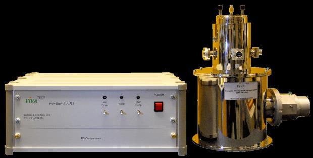
32 Cryogenic Primary Noise Standard VivaTech s Cryogenic Noise Standard is a noise source with primary reference performance. Providing precision calibration of low noise components such as amplifiers, diode noise sources or receiver systems, it offers the ultimate in performance. The unique design provides coverage from 18 to 500 GHz in standard waveguide bands, incorporating replaceable waveguide assemblies. The standard is particularly suited to mm and sub-mm wave [THz] low noise measurement applications. Side entry design enables convenient connections to waveguide systems Vertical or horizontal waveguide orientation no mismatched bends or twists needed Low maintenance, compact temperature stabilization system no water cooling Interchangeable waveguide feed-horn assemblies provide mm to sub-mm wave [THz] coverage Automatic or manual LN2 filling-auto fill minimizes LN2 use and allows continuous operation Convenient, fully automated operation with integrated PC Real time noise temperature display at any frequency with full data logging Frequency (GHz) Effective Noise Temperature (K) Feed-horn Assembly Waveguide VTA-42-NS VTA-28-NS VTA-15-NS VTA-10-NS VTA-8-NS VTA-6-NS VTA-5-NS VTA-3.4FA-NS VTA-3.4FB-NS VTA-2.2FA-NS VTA-2.2FB-NS WR 42 WR 28 WR 3.4 WR 3.4 WR 2.2 WR 2.2 Typical Output Temperature Display 1. Typical average mid band noise temperature 2. How to make a request: Indicate the feed-horn assembly (s) required listed above; Specify manual or automatic liquid nitrogen filling. [Auto fill also adds a 35 litre LN2 dewar], send mail to: sales@vivatech.biz 32
Millimeter Wave Product Catalogue VivaTech Consulting S.A.R.L.
 VivaTech Consulting S.A.R.L. sales@vivatech.biz Telephone: +33 04 89 01 14 61 Fax: +33 04 93 87 08 66 Table of Contents Millimeter Wave Low Noise Amplifiers VTLNA Series...3 Millimeter Wave Power Amplifiers
SERIES MXP BALANCED MIXERS FEATURES: APPLICATIONS: DESCRIPTION
 BALANCED MIXERS FEATURES: Low conversion loss and noise figure 13 dbm LO drive power Matched IF amplifier and LO offered Small, rugged package APPLICATIONS: DESCRIPTION Millitech series MXP balanced mixers
MICROWAVE MICROWAVE TRAINING BENCH COMPONENT SPECIFICATIONS:
 Microwave section consists of Basic Microwave Training Bench, Advance Microwave Training Bench and Microwave Communication Training System. Microwave Training System is used to study all the concepts of
SERIES DET GENERAL PURPOSE DETECTORS DESCRIPTION. Millimeter-Wave Technology & Solutions
 GENERAL PURPOSE DETECTORS FEATURES: Full waveguide bandwidth High sensitivity No tuning required Zero bias APPLIC ATIONS: Instrumentation Power monitoring DESCRIPTION Millitech series DET detectors, utilizing
FREQUENCY MULTIPLIERS
 MULTIPLIERS A series of broadband frequency multipliers is available with output frequencies between 18 and 110 GHz. The use of GaAs diodes on a suspended substrate circuit allows an extremely compact
Millimeter Wave Components & Subsystems. Airport East Business Park, Farmers Cross, Cork, Ireland
 - 0 - Contents Mixers and Detectors Low Cost Planar Detectors to 170 GHz...4 Waveguide Detectors to 325 GHz SERIES WD.. 6 Balanced Mixers SERIES BMC 8 Harmonic Mixers... 10 Subharmonically Pumped Mixers
AMPLIFIERS, ANTENNAS, MULTIPLIERS, SOURCES, WAVEGUIDE PRODUCTS MILLIMETER-WAVE COMPONENTS FERRITE PRODUCTS AND SUB-SYSTEMS
 AMPLIFIERS, ANTENNAS, MULTIPLIERS, SOURCES, WAVEGUIDE PRODUCTS MILLIMETER-WAVE COMPONENTS FERRITE PRODUCTS AND SUB-SYSTEMS 766 San Aleso Avenue, Sunnyvale, C A 94085 Tel. (408) 541-9226, Fax (408) 541-9229
Double-Ridged Waveguide Horn
 Model 3106 200 MHz 2 GHz Uniform Gain Power Handling up to 1.6 kw Model 3115 1 GHz 18 GHz Low VSWR Model 3116 18 GHz 40 GHz Quality Construction M O D E L 3 1 0 6 Double-Ridged Waveguide Horn PROVIDING
Ultra High Frequency Measurements
 Ultra High Frequency Measurements Desmond Fraser desmond@rheintech.com 703.689.0368 360 Herndon Parkway Suite 1400 Herndon, VA 20170 IEEE EMC DC / N. VA Chapter 31 January 2012 Overview We ll review Millimeter
Table of Contents. About SAGE Millimeter, Inc...1 Radar basics and related SAGE Millimeter microwave sensor technologies... 2
 A. INTRODUCTION About SAGE Millimeter, Inc.....1 Radar basics and related SAGE Millimeter microwave sensor technologies... 2 B. OSOCILLATORS (SOL Series) K band mechanically tuned Gunn oscillators......5
Banded Milimeter Wave Network Analysis TECHNICAL OVERVIEW
 Banded Milimeter Wave Network Analysis TECHNICAL OVERVIEW Banded Measurement Solutions to 1.5 THz Keysight offers a variety of banded millimeter-wave solutions that enable the PNA/ PNA-X network analyzers
RS3400W/04 77 GHz Radar Sensor
 Features Complete 76-77GHz band FMCW Radar Front End Synthesized frequency source Wideband Sweep Description The RS34W/4 is a W-band FMCW radar front end featuring synthesized frequency sweeps. A fast
Harmonic Mixers And their application with Spectrum Analysers Application Note Revision: February 2009
 General A harmonic mixer is another term for a sub-harmonic mixer (SHM) but is more commonly used for systems using higher multiples of the input local oscillator (LO) to produce the mixing LO. They lend
MILLIMETER WAVE SOURCE MODULE BROCHURE
 MILLIMETER WAVE SOURCE MODULE BROCHURE - 1 - General Information OML millimeter wave source modules connect the RF output of your existing signal generar extend microwave outputs millimeter and sub-millimeter
Microwave. Accessories for Microwave Scalar and System Analyzers
 Microwave Accessories for Microwave Scalar and System Analyzers The following optional accessories are designed for use with the 6200B series of Microwave Test Sets, the 6820 series Scalar Analyzers and
87415A microwave system amplifier A microwave. system amplifier A microwave system amplifier A microwave.
 20 Amplifiers 83020A microwave 875A microwave 8308A microwave 8307A microwave 83006A microwave 8705C preamplifier 8705B preamplifier 83050/5A microwave The Agilent 83006/07/08/020/050/05A test s offer
Multi-Function Assemblies
 K&L Microwave offers a variety of (MFA) products to satisfy a broad range of filtering applications. Many applications require frequency pre-selection at the front end of the communication or test and
Parameter Min. Typ. Max. Units
 v4.112 Typical Applications The is ideal for: Point-to-Point and Point-to-Multi-Point Radio Military Radar, EW & ELINT Satellite Communications Functional Diagram Features General Description The is a
SC5407A/SC5408A 100 khz to 6 GHz RF Upconverter. Datasheet. Rev SignalCore, Inc.
 SC5407A/SC5408A 100 khz to 6 GHz RF Upconverter Datasheet Rev 1.2 2017 SignalCore, Inc. support@signalcore.com P R O D U C T S P E C I F I C A T I O N S Definition of Terms The following terms are used
Matched EW/ECM Subsystems 2-18 GHz
 FEATURES: FREQUENCY RANGE COMPLEMENTARY MATCHED Rx & Tx MODULES RF PROCESSOR & DRFM DIRECT INTERFACE HIGH SENSITIVITY HIGH DYNAMIC RANGE FOR MILITARY TACTICAL ENVIRONMENT GENERAL Datasheet 39 INTEGRATED
PRODUCT CATALOG MICROWAVE & MILLIMETER WAVE COMPONENTS & SUB-ASSEMBLIES 5 TO 325 GHZ
 PRODUCT CATALOG MICROWAVE & MILLIMETER WAVE COMPONENTS & SUB-ASSEMBLIES AMPLIFIERS ANTENNAS CONTROL COMPONENTS UP/DOWN CONVERTERS FERRITE COMPONENTS WAVEGUIDE COMPONENTS SUB-ASSEMBLIES GUNN OSCILLATORS
K-LC2 RADAR TRANSCEIVER
 Features 24 GHz K-band miniature I/Q transceiver 140MHz sweep FM input 2 x 4 patch antenna 2 balanced mixer with 50MHz bandwidth Excellent noise cancelling ability though I/Q technology Beam aperture 80
Signal Generator Extension Modules Operational Manual
 216 Signal Generator Extension Modules Operational Manual 979 Second Street SE, Suite 39 Charlottesville, VA 2292-6172 (USA) Tel: 434.297.327; Fax: 434.297.328 www.vadiodes.com 21 Virginia Diodes, Inc
Heterodyne Sweeping Radiometer
 46 Robezu str. LV-1004 Riga, Latvia Fax: +371-7-065102 Mm-wave Division in St. Petersburg, Russia Fax: +7-812- 326-10-60 Tel: +7-812-326-59-24 E-mail: ivanovph@nnz.ru Heterodyne Sweeping Radiometer Operation
Advanced Test Equipment Rentals ATEC (2832)
") Established 1981 Advanced Test Equipment Rentals www.atecorp.com 800-404-ATEC (2832) Agilent 2-Port and 4-Port PNA-X Network Analyzer N5249A - 10 MHz to 8.5 GHz N5241A - 10 MHz to 13.5 GHz N5242A - 10
Established 1981 Advanced Test Equipment Rentals www.atecorp.com 800-404-ATEC (2832) Agilent 2-Port and 4-Port PNA-X Network Analyzer N5249A - 10 MHz to 8.5 GHz N5241A - 10 MHz to 13.5 GHz N5242A - 10
CUSTOM INTEGRATED ASSEMBLIES
 17 CUSTOM INTEGRATED ASSEMBLIES CUSTOM INTEGRATED ASSEMBLIES Cougar offers full first-level integration capabilities, providing not just performance components but also full subsystem solutions to help
Keysight 2-Port and 4-Port PNA-X Network Analyzer
 Keysight 2-Port and 4-Port PNA-X Network Analyzer N5249A - 0 MHz to 8.5 GHz N524A - 0 MHz to 3.5 GHz N5242A - 0 MHz to 26.5 GHz Data Sheet and Technical Specifications Documentation Warranty THE MATERIAL
SAGE Millimeter, Inc.
 Description: Model SAF-2434233-328-S1-28-DP is a dual polarized, WR-28 scalar feed horn antenna assembly that covers several popular G bands in the frequency range of 24 to 42 GHz. The antenna features
DSA700 Series Spectrum Analyzer
 DSA700 Series Spectrum Analyzer Product Features: All-Digital IF Technology Frequency Range from 100 khz up to 1 GHz Min. -155 dbm Displayed Average Noise Level (Typ.) Min.
Microwave Antennas making the world smaller
 Microwave Antennas making the world smaller www.procom.dk Index MICROWAVE ANTENNAS 10 GHz Omnidirectional Antennas WGSL 10 2 Parabolic Antennas PRO-10-001/25 3 PRO-10-001/50 4 Accessories PRO-10-... 5
Keysight Technologies N9320B RF Spectrum Analyzer
 Keysight Technologies N9320B RF Spectrum Analyzer 9 khz to 3.0 GHz Data Sheet Definitions and Conditions The spectrum analyzer will meet its specifications when: It is within its calibration cycle It has
ASTRO 25 The STR 3000 is compatible with Project MHz and 800 MHz trunking systems.
 Specification Sheet STR 3000 Pre-packaged Digital Base Radio Sub-System The STR 3000 provides the transmit/receive operation within the ASTRO 25 sub-system. Its components include 1 to 6 base radios, multicoupler(s),
60 GHz RX. Waveguide Receiver Module. Features. Applications. Data Sheet V60RXWG3. VubIQ, Inc
 GHz RX VRXWG Features Complete millimeter wave receiver WR-, UG-8/U flange Operates in the to GHz unlicensed band db noise figure Up to.8 GHz modulation bandwidth I/Q analog baseband interface Integrated
Agilent ESA-L Series Spectrum Analyzers
 Agilent ESA-L Series Spectrum Analyzers Data Sheet Available frequency ranges E4403B E4408B 9 khz to 1.5 GHz 9 khz to 3.0 GHz 9 khz to 26.5 GHz As the lowest cost ESA option, these basic analyzers are
CobaltFx Series EXTEND YOUR REACH. Frequency Extender System from. Frequency bands from: GHz, GHz, GHz
 CobaltFx Series TM Frequency Extender System from TM Frequency bands from: 50-75 GHz, 60-90 GHz, 75-110 GHz EXTEND YOUR REACH USA: +1.17..5400 61 E. New York St Indianapolis, IN 460 www.coppermountaintech.com
Agilent N9320B RF Spectrum Analyzer
 Agilent N9320B RF Spectrum Analyzer 9 khz to 3.0 GHz Data Sheet Definitions and Conditions The spectrum analyzer will meet its specifications when: It is within its calibration cycle It has been turned
Development of high cost performance signal analyzer MS2830A -044/045
 Development of high cost performance signal analyzer MS2830A -044/045 Yuji Kishi, Shuichi Matsuda, Koichiro Tomisaki, Kozo Yokoyama, Yoshiaki Yasuda, Tsukasa Yasui, Kota Kuramitsu [Summary] We have developed
60 GHz Receiver (Rx) Waveguide Module
 Waveguide Module") The PEM is a highly integrated millimeter wave receiver that covers the GHz global unlicensed spectrum allocations packaged in a standard waveguide module. Receiver architecture is a double conversion,
The PEM is a highly integrated millimeter wave receiver that covers the GHz global unlicensed spectrum allocations packaged in a standard waveguide module. Receiver architecture is a double conversion,
Keysight Technologies PNA Microwave Network Analyzers
 Keysight Technologies PNA Microwave Network Analyzers Application Note Banded Millimeter-Wave Measurements with the PNA 02 Keysight PNA Microwave Network Analyzers Application Note Table of Contents Introduction...
Engineering the high quality cost effective solutions. Short form selection catalogue
 Engineering the high quality cost effective solutions Short form selection catalogue 19 Rack mountable systems NML offers variety of upconverters, downconverters, multicouplers, synthesisers for various
Agilent 83554A/83555A/83556A mm-wave Source Modules* Data Sheet
 View at www.testequipmentdepot.com Agilent 83554A/83555A/83556A mm-wave Source Modules* Data Sheet 26.5 to 40.0 GHz 33.0 to 50.0 GHz 40.0 to 60.0 GHz Precision and power from a millimeter-wave swept solution
5G and mmwave Testing
 5G and mmwave Testing 5G and mmwave Testing The development and deployment of 5G technology is changing the way wireless carriers and internet service providers think about meeting the ever increasing
CONTENTS MEASUREMENT INSTRUMENTS AND W/G COMPONENTS FOR SUBMILLIMETER WAVES
 2 CONTENTS Scalar Network Analyzer 3 Direct Reading Attenuator 4 Direct Reading Attenuator with remote control 5 Calorimetric Power Meter 6 Waveguide Switch 7 Waveguide Tapered Transitions 8 Rectangular
SAGE Millimeter, Inc.
 Description: Model SAM-5735930395-15-L1-4W is a linear polarized, 58 GHz microstrip patch 1 x 4 array antenna. The antenna array implements four individual antenna ports so that beamforming can be achieved
Features OBSOLETE. = +25 C, IF= 1 GHz, USB, LO = +15 dbm [1]
![Features OBSOLETE. = +25 C, IF= 1 GHz, USB, LO = +15 dbm [1]](/thumbs/82/84974573.jpg "Features OBSOLETE. = +25 C, IF= 1 GHz, USB, LO = +15 dbm [1]") v1.414 HMC141LC4 Typical Applications The HMC141LC4 is Ideal for: Point-to-Point Radio Point-to-Multi-Point Radio Test Equipment & Sensors Military End Use Functional Diagram Features Wide IF Bandwidth:
v1.414 HMC141LC4 Typical Applications The HMC141LC4 is Ideal for: Point-to-Point Radio Point-to-Multi-Point Radio Test Equipment & Sensors Military End Use Functional Diagram Features Wide IF Bandwidth:
Banded Millimeter Wave Network Analysis TECHNICAL OVERVIEW
 Banded Millimeter Wave Network Analysis TECHNICAL OVERVIEW Banded Measurement Solutions to 1.5 THz Keysight offers a variety of banded millimeter-wave solutions that enable the PNA/ PNA-X network analyzers
AV3672 Series Vector Network Analyzer
 AV3672 Series Vector Network Analyzer AV3672A/B/C/D/E (10MHz 13.5 GHz/26.5 GHz/43.5 GHz/50 GHz/67 GHz) Product Overview: AV3672 series vector network analyzer include AV3672A (10MHz 13.5GHz), AV3672B (10MHz
RF Components Product Catalogue
 RF Components Product Catalogue Government and Defence Broadcast Marine, Oil and Gas SNG and VSAT RF Engineering by Design Contents Splitters / Combiners Active Splitters and Combiners Page 3 Passive Splitters
Integrated Microwave Assemblies
 Integrated Microwave Assemblies Integrated Microwave Assembly (IMA) Custom Solutions For more information please call us at 888.553.7531 API Technologies, a world class leader in component design and system
Multifunctional Microwave Analyzer
 AV4958 (1MHz~20GHz) Multifunctional Microwave Analyzer Product Overview AV4958 Multifunctional Microwave Analyzer integrates multiple functions, such as tests of cable and antenna SWR, distance to fault(dtf),
SERIES PLS PHASE LOCKED SYNTHESIZER. FEATURES: Small Size, Low Cost, Simple to use Low Phase Noise Auto-sensing Internal or External 10MHz Reference
 PHASE LOCKED SYNTHESIZER FEATURES: Small Size, Low Cost, Simple to use Low Phase Noise Auto-sensing Internal or External 10MHz Reference Can be utilized as a synthesizer, or a fixed frequency oscillator
FREQUENCY MULTIPLIERS
 FREQUENCY MULTIPLIERS ISO 9001 REGISTERED COMPANY PASSIVE AND ACTIVE Doublers Triplers Higher-Order Products TABLE OF CONTENTS CONTENTS PAGE INTRODUCTION 2 TECHNICAL OVERVIEW 2 Technical Discussion 3 Design
Understanding RF and Microwave Analysis Basics
 Understanding RF and Microwave Analysis Basics Kimberly Cassacia Product Line Brand Manager Keysight Technologies Agenda µw Analysis Basics Page 2 RF Signal Analyzer Overview & Basic Settings Overview
Ka Band Radar Transceiver
 Ka Band Radar Transceiver Ka-Band Radar Transceiver with Integrated LO Source Homodyne System with Integrated TX & LO Multiplied VCO with Phase noise
Features. Upconversion & Downconversion Applications MIXERS - SINGLE & DOUBLE BALANCED - SMT
 v1. Typical Applications The HMC689LP4(E) is Ideal for: Cellular/3G & LTE/WiMAX/4G Basestations & Repeaters GSM, CDMA & OFDM Transmitters and Receivers Features High Input IP3: +32 dbm Low Conversion Loss:
SUNSTAR 微波光电 TEL: About Technologies was founded in the beginning of 2. is committed to providing our customers with
 343 Kashiwa Street Torrance, CA 9 Telephone: 3-39-8882 Fax: 3-39-8862 E Mail: sales@wisewave-inc.com URL: www.wisewave-inc.com Copyright 24 by SUNSTAR 微波光电 http://www.rfoe.net/ TEL:7-83396822 24 Microwave
Agilent 8360B/8360L Series Synthesized Swept Signal/CW Generators 10 MHz to 110 GHz
 Agilent 8360B/8360L Series Synthesized Swept Signal/CW Generators 10 MHz to 110 GHz ity. l i t a ers V. n isio c e r P. y t i l i ib Flex 2 Agilent 8360 Synthesized Swept Signal and CW Generator Family
Keysight Technologies Gustaaf Sutorius
 1 1 mmw Seminar 2017 Keysight Technologies 18-04-2018 Gustaaf Sutorius Introduction & Agenda Why mmwave Industry needs & mmwave challenges Generating mmwave Analyzing mmwave Characterizing mmwave components
Manufacturers of RF and Microwave Components and Assemblies Specialist in RF Filters, Power amplifiers and RF Switches
 Manufacturers of RF and Microwave Components and Assemblies Specialist in RF Filters, Power amplifiers and RF Switches sales@cormic.com www.cormic.com P 724.940.7556 F 724.940.7707 RF & MICROWAVE FILTERS
Cavity Filters. Waveguide Filters
 Cavity Cavity Filters K&L Microwave s series of cavity filters covers the frequency range from 30 MHz to 40 GHz. These filters are available with 2 to 17 resonant sections and bandwidths from 0.2% to 50%.
USER OPERATION AND MAINTENANCE MANUAL
 46 Robezu str. LV-1004 Riga Latvia Phone: +371-7-065-100, Fax: +371-7-065-102 Mm-wave Division in St. Petersburg, Russia Phone: +7-812-326-5924, Fax: +7-812-326-1060 USER OPERATION AND MAINTENANCE MANUAL
Elisra MMIC Catalog MMIC Catalog
 October 21 Elisra MMIC Catalog MMIC Catalog Unclassified 5 Bit DCA.518GHz 5 Bit DCA.518GHz DESCRIPTION Frequency Range Attenuation Range (simultaneous) LSB = 1 ; MSB = 16 Phase variation over all states
Agilent 2-Port and 4-Port PNA-X Network Analyzer. N5241A - 10 MHz to 13.5 GHz N5242A - 10 MHz to 26.5 GHz Data Sheet and Technical Specifications
 Agilent 2-Port and 4-Port PNA-X Network Analyzer N5241A - 10 MHz to 13.5 GHz N5242A - 10 MHz to 26.5 GHz Data Sheet and Technical Specifications Documentation Warranty THE MATERIAL CONTAINED IN THIS DOCUMENT
Features. = +25 C, IF = 200 MHz, LO = 0 dbm, Vcc = Vcc1, 2, 3 = +5V, G_Bias = +2.5V*
 v4.1 Typical Applications The HMC685LP4(E) is Ideal for: Cellular/3G & LTE/WiMAX/4G Basestations & Repeaters GSM, CDMA & OFDM Transmitters and Receivers Features High Input IP3: +35 dbm 8 db Conversion
Keysight Spectrum Analyzer Option (090/S93090xA) for PNA/PNA-L/PNA-X/N5290A/N5291A
 for PNA/PNA-L/PNA-X/N5290A/N5291A") Keysight Spectrum Analyzer Option (090/S93090xA) for PNA/PNA-L/PNA-X/N5290A/N529A Data Sheet and Technical Specifications Documentation Warranty THE MATERIAL CONTAINED IN THIS DOCUMENT IS PROVIDED "AS
Keysight Spectrum Analyzer Option (090/S93090xA) for PNA/PNA-L/PNA-X/N5290A/N529A Data Sheet and Technical Specifications Documentation Warranty THE MATERIAL CONTAINED IN THIS DOCUMENT IS PROVIDED "AS
772D coaxial dual-directional coupler 773D coaxial directional coupler. 775D coaxial dual-directional coupler 776D coaxial dual-directional coupler
 72 772D coaxial dual-directional coupler 773D coaxial directional coupler 775D coaxial dual-directional coupler 776D coaxial dual-directional coupler 777D coaxial dual-directional coupler 778D coaxial
THz Vector Network Analyzer Development & Measurements
 THz Vector Network Analyzer Development & Measurements Jeffrey L Hesler, Yiwei Duan, Brian Foley and Thomas Crowe Virginia Diodes Inc., Charlottesville, VA, USA Abstract: Virginia Diodes has been developing
60 GHz TX. Waveguide Transmitter Module. Data Sheet Features V60TXWG3. Applications. VubIQ, Inc
 Features Complete millimeter wave transmitter WR-, UG-8/U flange Operates in the to GHz unlicensed band dbm typical output power Up to.8 GHz modulation bandwidth I/Q analog baseband interface On chip synthesizer
Keysight Technologies Making Accurate Intermodulation Distortion Measurements with the PNA-X Network Analyzer, 10 MHz to 26.5 GHz
 Keysight Technologies Making Accurate Intermodulation Distortion Measurements with the PNA-X Network Analyzer, 10 MHz to 26.5 GHz Application Note Overview This application note describes accuracy considerations
INC. MICROWAVE. A Spectrum Control Business
 DRO Selection Guide DIELECTRIC RESONATOR OSCILLATORS Model Number Frequency Free Running, Mechanically Tuned Mechanical Tuning BW (MHz) +10 MDR2100 2.5-6.0 +10 6.0-21.0 +20 Free Running, Mechanically Tuned,
ytivac Cavity Filters
 Cavity Cavity Filters K&L Microwave s series of cavity filters covers the frequency range from 30 MHz to 40 GHz. These filters are available with 2 to 17 resonant sections and bandwidths from 0.2% to 50%.
Optiva OTS-2 40 GHz Amplified Microwave Band Fiber Optic Links
 5 MHz to 4 GHz Amplified Microwave Transport System The Optiva OTS-2 4 GHz Microwave Band transmitter and receiver are ideal to construct transparent fiber optic links in the 5 MHz to 4 GHz frequency range
Using the OML Millimeter Wave Vector Network Analyzer Frequency Extension Modules with the HP 8510 Vector Network Analyzer
 Using the OML Millimeter Wave Vector Network Analyzer Frequency Extension Modules with the HP 8510 Vector Network Analyzer OML has developed a series of millimeter wave Frequency Extension Modules (Modules)
Designed and Manufactured in England to the highest standards
 +44 (0) 168 612138 +44 (0) 168 616373 CATALOGUE OF WAVEGUIDE HORS Qpar Angus designs and manufactures microwave components and antenna systems, across the radio frequency spectrum from decimetre to submillimetre
Block Upconverters for Integration in High Power Amplifiers
 R Back to Block/Fixed Tuned Converters Block Upconverters for Integration in High Power Amplifiers Block Upconverters For Integration In High Power Amplifiers C-, X- and Ku-Band Models (except UPBA-13)
Optiva OTS-2 18 GHz Amplified Microwave Band Fiber Optic Links
 MHz to 18 GHz Amplified Microwave Transport System The Optiva OTS-2 18 GHz Microwave Band transmitter and receiver are ideal to construct transparent fiber optic links in the MHz to 18 GHz frequency range
SC5307A/SC5308A 100 khz to 6 GHz RF Downconverter. Datasheet SignalCore, Inc.
 SC5307A/SC5308A 100 khz to 6 GHz RF Downconverter Datasheet 2017 SignalCore, Inc. support@signalcore.com P RODUCT S PECIFICATIONS Definition of Terms The following terms are used throughout this datasheet
FS5000 COMSTRON. The Leader In High Speed Frequency Synthesizers. An Ideal Source for: Agile Radar and Radar Simulators.
 FS5000 F R E Q U E N C Y S Y N T H E S I Z E R S Ultra-fast Switching < 200 nsec Wide & Narrow Band Exceptionally Clean An Ideal Source for: Agile Radar and Radar Simulators Radar Upgrades Fast Antenna
MICROWAVE ASSEMBLIES, SYSTEMS AND TECHNOLOGIES
 MICROWAVE ASSEMBLIES, SYSTEMS AND TECHNOLOGIES ISO 9001 REGISTERED COMPANY PIN Switches Broadband Power Dividers 3 db Hybrids Analog PIN Attenuators Phase Shifters Modulators Couplers Limiters Custom Integrated
ModBox - Spectral Broadening Unit
 ModBox - Spectral Broadening Unit The ModBox Family The ModBox systems are a family of turnkey optical transmitters and external modulation benchtop units for digital and analog transmission, pulsed and
Who We Are. Antennas Space Terahertz
 Anteral Products Who We Are Anteral was born in 2011 as a spin-off of the Public University of Navarra (UPNA) Antenna Group. It is a technological company with an innovative profile. Anteral is focused
325 to 500 GHz Vector Network Analyzer System
 325 to 500 GHz Vector Network Analyzer System By Chuck Oleson, Tony Denning and Yuenie Lau OML, Inc. Abstract - This paper describes a novel and compact WR-02.2 millimeter wave frequency extension transmission/reflection
Data Sheet SC5317 & SC5318A. 6 GHz to 26.5 GHz RF Downconverter SignalCore, Inc. All Rights Reserved
 Data Sheet SC5317 & SC5318A 6 GHz to 26.5 GHz RF Downconverter www.signalcore.com 2018 SignalCore, Inc. All Rights Reserved Definition of Terms 1 Table of Contents 1. Definition of Terms... 2 2. Description...
Features. Upconversion & Downconversion Applications MIXERS - SINGLE & DOUBLE BALANCED - SMT
 v1. Typical Applications The HMC688LP4(E) is Ideal for: Cellular/3G & LTE/WiMAX/4G Basestations & Repeaters GSM, CDMA & OFDM Transmitters and Receivers Features High Input IP3: +35 dbm Low Conversion Loss:
Optiva OTS-2 40 GHz Amplified Microwave Band Fiber Optic Links
 2 GHz to 4 GHz Amplified Microwave Transport System The Optiva OTS-2 4 GHz Microwave Band transmitter and receiver are ideal to construct transparent fiber optic links in the 5 MHz to 4 GHz frequency range
Dinesh Micro Waves & Electronics
 Wave Guide Components RECTANGULAR WAVE GUDES Dinesh Microwaves and Electronics manufacturers of high power waveguide in the microwaves industry, this experience had resulted in designing, manufacturing
and GHz. ECE Radiometer. Technical Description and User Manual
 E-mail: sales@elva-1.com http://www.elva-1.com 26.5-40 and 76.5-90 GHz ECE Radiometer Technical Description and User Manual November 2008 Contents 1. Introduction... 3 2. Parameters and specifications...
FMMX9003 DATA SHEET. Field Replaceable SMA IQ Mixer From 11 GHz to 16 GHz With an IF Range From DC to 3.5 GHz And LO Power of +19 dbm.
 FMMX93 Field Replaceable SMA IQ Mixer From 11 GHz to 16 GHz With an IF Range From DC to 3.5 GHz And LO Power of +19 dbm FMMX93 is an I/Q double balanced millimeter-wave mixer module that operates across
SIGNAL GENERATORS. MG3633A 10 khz to 2700 MHz SYNTHESIZED SIGNAL GENERATOR GPIB
 SYNTHESIZED SIGNAL GENERATOR MG3633A GPIB For Evaluating of Quasi-Microwaves and Measuring High-Performance Receivers The MG3633A has excellent resolution, switching speed, signal purity, and a high output
Holography Transmitter Design Bill Shillue 2000-Oct-03
 Holography Transmitter Design Bill Shillue 2000-Oct-03 Planned Photonic Reference Distribution for Test Interferometer The transmitter for the holography receiver is made up mostly of parts that are already
QuickSyn Frequency Synthesizers
 QuickSyn Frequency Synthesizers The QuickSyn Advantage Our popular line of QuickSyn frequency synthesizers delivers instrumentgrade performance up to 82 GHz, increased functionality, and efficient power
1:1 AND 1:2 REDUNDANT LOW-NOISE AMPLIFIER SYSTEMS
 FEATURES Low amplifier noise temperature Fully redundant power supplies Remote control via RS485 matic/manual control from both local and remote mode Remote status Off-line input/output access Amplifier
Platform Migration 8510 to PNA. Graham Payne Application Engineer Agilent Technologies
 Platform Migration 8510 to PNA Graham Payne Application Engineer Agilent Technologies We set the standard... 8410 8510 When we introduced the 8510, we changed the way S-parameter measurements were made!
A Broadband T/R Front-End of Millimeter Wave Holographic Imaging
 Journal of Computer and Communications, 2015, 3, 35-39 Published Online March 2015 in SciRes. http://www.scirp.org/journal/jcc http://dx.doi.org/10.4236/jcc.2015.33006 A Broadband T/R Front-End of Millimeter
Chapter 5 Specifications
 RIGOL Specifications are valid under the following conditions: the instrument is within the calibration period, is stored for at least two hours at 0 to 50 temperature and is warmed up for 40 minutes.
Keysight Technologies E8257D PSG Microwave Analog Signal Generator. Data Sheet
 Keysight Technologies E8257D PSG Microwave Analog Signal Generator Data Sheet 02 Keysight E8257D Microwave Analog Signal Generator - Data Sheet Table of Contents Specifications... 4 Frequency... 4 Step
CHAPTER - 6 PIN DIODE CONTROL CIRCUITS FOR WIRELESS COMMUNICATIONS SYSTEMS
 CHAPTER - 6 PIN DIODE CONTROL CIRCUITS FOR WIRELESS COMMUNICATIONS SYSTEMS 2 NOTES 3 INTRODUCTION PIN DIODE CONTROL CIRCUITS FOR WIRELESS COMMUNICATIONS SYSTEMS Chapter 6 discusses PIN Control Circuits
CMOS 5GHz WLAN ac RFeIC WITH PA, LNA AND SPDT
 CMOS 5GHz WLAN 802.11ac RFeIC WITH PA, LNA AND SPDT RX LEN 16 RXEN ANT 15 14 13 12 11 Description RFX8051B is a highly integrated, single-chip, single-die RFeIC (RF Front-end Integrated Circuit) which
DS H01 DIGITAL SYNTHESIZER MODULE SYSTEM SOLUTIONS. Features Applications 174 x 131 x 54 mm. Technical Description
 DS H01 The DS H01 is a high performance dual digital synthesizer with wide output bandwidth specially designed for Defense applications where generation of wideband ultra-low noise signals along with very
CORRY MICRONICS, INC. 761 COMMONWEALTH DRIVE SUITE 201 WARRENDALE, PA P F
 CORRY MICRONICS, INC. 761 COMMONWEALTH DRIVE SUITE 201 WARRENDALE, PA 15086 P 724.940.7556 F 724.940.7707 EMAIL: SALES@CORMIC.COM WWW.CORMIC.COM Manufacturers of RF and Microwave Components and Assemblies