Implementation of a Fuzzy Logic-Based Embedded System for Engine RPM Control. (Speed Control)
|
|
|
- Pauline O’Brien’
- 5 years ago
- Views:
Transcription
1 Implementation of a Fuzzy Logic-Based Embedded System for Engine RPM Control (Speed Control)
2 Introduction implements an embedded system for the Engine RPM control based on a development board developed around an Arduino Mega board fuzzy logic system as controller offers an easy understanding of the main concepts regarding embedded systems
3 System implementation Block diagram

4 DC-Motor: Gear ratio: 30:1 Free run speed at 6V: 1000RPM Free run current at 6V: 120mA Stall current at 6V: 1600mA
 across an electrical conductor: transverse to an electric current in the")
5 Hall Effect Sensor B [What is Hall Effect and How Hall Effect Sensors Work, The Hall effect: the production of a voltage difference (the Hall voltage) across an electrical conductor: transverse to an electric current in the conductor an applied magnetic field perpendicular to the current.


6 Hall Effect Sensor cont. [ -it-works/electrical-engineering/halleffect-hall-effect-sensors-work/]


7 Quadrature Encoder: Six pole magnetic disk +PCB Dual Channel 12 counts/revolution 2.8V -18V Output signal of the encoder
8 Motor Driver: L298 - Dual Full Bridge Driver (H bridge) Middle class 2 Motors Sensors power supply
9 Motor Driver: L298 - Dual Full Bridge Driver (H bridge) Middle class 2 Motors Sensors power supply How the RPM can be controlled?


10 Arduino Mega Pinout LCD screen
11 The Arduino Mega board is the brain of the entire system. It is primarily responsible for the update of the digital control signal u, at every time instance. The actual RPM, RPM k is read and the actual RPM error (err k ) and change of RPM error (cerr k ) are updated, as follows: err k = RPM k RPM ref cerr k = err k err k 1 where err k 1 is the RPM error in the previous time instance. The star of the entire system is the fuzzy logic controller, whose role is to infer the best modification in the control signal, in every time instance. The digital version of the actual control signal is updated using the relation: u k = u k 1 + Δu k
12 To obtain the actual RPM: RPM computation a method based on a fixed time interval (time window) to count the revolutions of the main motor shaft. a counter is triggered at the initial time t i and it counts the pulses received from the Hall effect sensor up to the final increment t f. The RPM is computed using the relation : C f - final value of the counter C i - initial value of the counter C r = 12 counts per revolution G r = 30, the gear ratio (30:1) t f, t i are measured in seconds RPM = C f C i t f t i 1 C r 1 G r
13 RPM computation C f - final value of the counter C i - initial value of the counter RPM = C f C i 1 1 C r = 12 counts per revolution t f t i C r G r G r = 30, the gear ratio (30:1) t f, t i are measured in milliseconds

14 first-order Takagi-Sugeno two inputs errfls and cerrfls one output ΔuFls The Fuzzy Logic Controller Fuzzy sets for the inputs Fuzzy sets for the output

15 Block diagram of the fuzzy logic controller errfls cerrfls Neg Zero Pos Neg N N Z Zero N Z P Pos Z P P Rule base of the fuzzy logic system
16 The defuzzification method, used to transform the partial output fuzzy sets resulted from the inference process into a crisp value is the weighted average method.

17 output Control surface of the fuzzy logic controller Err cerr
18 Control Circuit RPM ref + _ RPM err 1 z _ + cerr s e s c errfls cerrfls Fuzzy logic system ΔuFls s u Δu z 255 u Motor Driver u a DC Motor

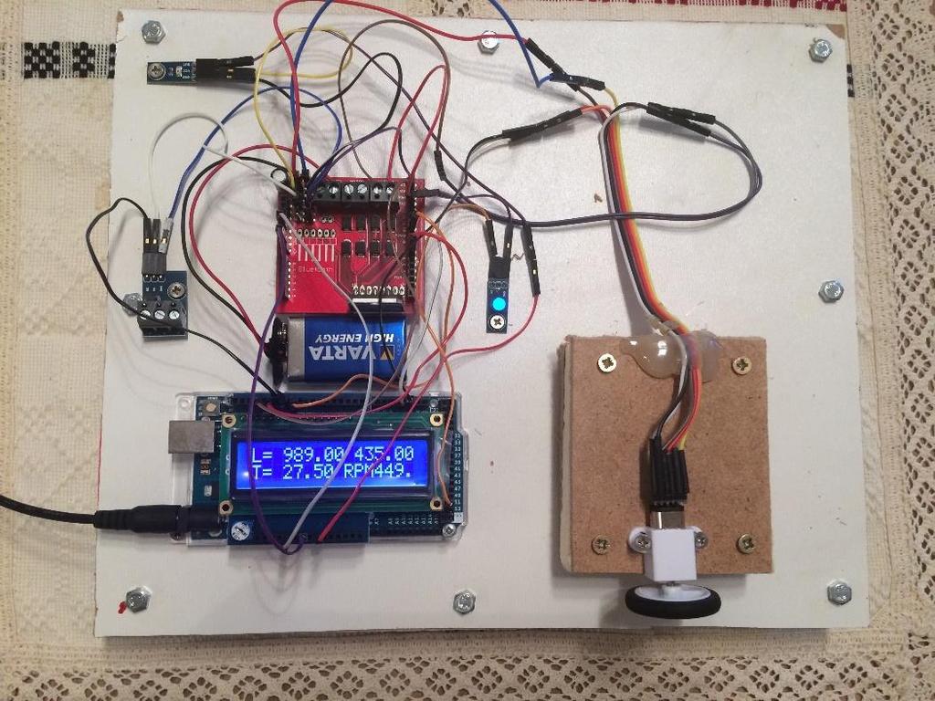
19 System setup
20 Experimental results RPM from 0 to 1000 rise time = 8.8 s; max. positive error = 5 rpm ; max. negative error = 5rpm; RPM from 1000 to 500 fall time = 6.75 s; max. positive error = 6 rpm ; max. negative error = 9rpm; RPM from 500 to 750 rise time = 4.75 s; max. positive error = 8 rpm ; max. negative error = 6rpm; RPM from 750 to 0 fall time = 6.5 s;
21
22 Decreasing the time response To drastically decrease the time response of the control system, the control strategy should be slightly modified. Because the control characteristic of the DC motor driven by the H-Bridge is almost liner, when a large variation of the motor speed is required (larger than 60 rpm), the control signal is not determined by the fuzzy logic system, but it is estimated by a simple linear interpolation, that acts as a course adjustment of the control signal. Then, the fuzzy logic system regains its role for the fine adjustment of the speed.
23

24 Tracking mode operation: RPM tracks the temperature variation

25 Duty Cycle 23% Low Speed 55% Medium Speed 90% High Speed
Implementation of a Temperature Control System using ARDUINO
 1. Implementation of a Temperature Control System using ARDUINO System structure Close control loop Fuzzy controller Fuzzy logic system: 9 rules Temperature Sensor One Wire Digital Temperature Sensor -
Dimensions: Specifications:
 Rover 5 Rover 5 is a new breed of tracked robot chassis designed specifically for students and hobbyist. Unlike conventional tracked chassis s the clearance can be adjusted by rotating the gearboxes in
ME375 Lab Project. Bradley Boane & Jeremy Bourque April 25, 2018
 ME375 Lab Project Bradley Boane & Jeremy Bourque April 25, 2018 Introduction: The goal of this project was to build and program a two-wheel robot that travels forward in a straight line for a distance
MOBILE ROBOT LOCALIZATION with POSITION CONTROL
 T.C. DOKUZ EYLÜL UNIVERSITY ENGINEERING FACULTY ELECTRICAL & ELECTRONICS ENGINEERING DEPARTMENT MOBILE ROBOT LOCALIZATION with POSITION CONTROL Project Report by Ayhan ŞAVKLIYILDIZ - 2011502093 Burcu YELİS
Assembly Language. Topic 14 Motion Control. Stepper and Servo Motors
 Assembly Language Topic 14 Motion Control Stepper and Servo Motors Objectives To gain an understanding of the operation of a stepper motor To develop a means to control a stepper motor To gain an understanding
CHAPTER 4 FUZZY LOGIC CONTROLLER
 62 CHAPTER 4 FUZZY LOGIC CONTROLLER 4.1 INTRODUCTION Unlike digital logic, the Fuzzy Logic is a multivalued logic. It deals with approximate perceptive rather than precise. The effective and efficient
MATHEMATICAL MODELS OF GEAR TOOTH SPEED SENSORS WITH DUAL OUTPUTS
 MATHEMATICAL MODELS OF GEAR TOOTH SPEED SENSORS WITH DUAL OUTPUTS Ji-Gou Liu 1 and Zhe Zheng 2 1 ChenYang Technologies GmbH & Co. KG., Finsing, Germany 2 University of Shanghai for Science and Technology,
A Comparison of Performance Characteristics of On and Off Axis High Resolution Hall Effect Encoder ICs
 A Comparison of Performance Characteristics of On and Off Axis High Resolution Hall Effect Encoder ICs Sensor Products Mark LaCroix A John Santos Dr. Lei Wang 8 FEB 13 Orlando Originally Presented at the
Basic NC and CNC. Dr. J. Ramkumar Professor, Department of Mechanical Engineering Micro machining Lab, I.I.T. Kanpur
 Basic NC and CNC Dr. J. Ramkumar Professor, Department of Mechanical Engineering Micro machining Lab, I.I.T. Kanpur Micro machining Lab, I.I.T. Kanpur Outline 1. Introduction to CNC machine 2. Component
Lab 5: Inverted Pendulum PID Control
 Lab 5: Inverted Pendulum PID Control In this lab we will be learning about PID (Proportional Integral Derivative) control and using it to keep an inverted pendulum system upright. We chose an inverted
DC Motor and Servo motor Control with ARM and Arduino. Created by:
 DC Motor and Servo motor Control with ARM and Arduino Created by: Andrew Kaler (39345) Tucker Boyd (46434) Mohammed Chowdhury (860822) Tazwar Muttaqi (901700) Mark Murdock (98071) May 4th, 2017 Objective
Product Family: 05, 06, 105, 205, 405, WinPLC, Number: AN-MISC-021 Terminator IO Subject: High speed input/output device
 APPLICATION NOTE THIS INFORMATION PROVIDED BY AUTOMATIONDIRECT.COM TECHNICAL SUPPORT These documents are provided by our technical support department to assist others. We do not guarantee that the data
L E C T U R E R, E L E C T R I C A L A N D M I C R O E L E C T R O N I C E N G I N E E R I N G
 P R O F. S L A C K L E C T U R E R, E L E C T R I C A L A N D M I C R O E L E C T R O N I C E N G I N E E R I N G G B S E E E @ R I T. E D U B L D I N G 9, O F F I C E 0 9-3 1 8 9 ( 5 8 5 ) 4 7 5-5 1 0
SPEED CONTROL OF INDUCTION MOTOR WITHOUT SPEED SENSOR AT LOW SPEED OPERATIONS
 SPEED CONTROL OF INDUCTION MOTOR WITHOUT SPEED SENSOR AT LOW SPEED OPERATIONS Akshay Prasad Dubey and Saravana Kumar R. School of Electrical Engineering, VIT University, Vellore, Tamil Nadu, India E-Mail:
Computer Numeric Control
 Computer Numeric Control TA202A 2017-18(2 nd ) Semester Prof. J. Ramkumar Department of Mechanical Engineering IIT Kanpur Computer Numeric Control A system in which actions are controlled by the direct
Sensors and Sensing Motors, Encoders and Motor Control
 Sensors and Sensing Motors, Encoders and Motor Control Todor Stoyanov Mobile Robotics and Olfaction Lab Center for Applied Autonomous Sensor Systems Örebro University, Sweden todor.stoyanov@oru.se 13.11.2014
DC motor control using arduino
 DC motor control using arduino 1) Introduction: First we need to differentiate between DC motor and DC generator and where we can use it in this experiment. What is the main different between the DC-motor,
DC Geared Motor with Encoder MO-SPG-30E-XXXK
 DC Geared Motor with Encoder MO-SPG-30E-XXXK USER S MANUAL V1.1 May 2011 Information contained in this publication regarding device applications and the like is intended through suggestion only and may
PIC Functionality. General I/O Dedicated Interrupt Change State Interrupt Input Capture Output Compare PWM ADC RS232
 PIC Functionality General I/O Dedicated Interrupt Change State Interrupt Input Capture Output Compare PWM ADC RS232 General I/O Logic Output light LEDs Trigger solenoids Transfer data Logic Input Monitor
Fuzzy Logic Based Speed Control of BLDC Motor
 Fuzzy Logic Based Speed Control of BLDC Motor Mahesh Sutar #1, Ashish Zanjade *2, Pankaj Salunkhe #3 # EXTC Department, Mumbai University. 1 Sutarmahesh4@gmail.com 2 Zanjade_aa@rediffmail.com 3 pasalunkhe@gmail.com
MIG Encoders BEGE MIG NOVA+ Your drive, our (trans)mission. BEGE Power Transmission
mission. BEGE Power Transmission") MIG Encoders BEGE MIG NOVA+ BEGE Power Transmission Anton Philipsweg 30 2171 KX Sassenheim The Netherlands T: +31 252-220 220 E: bege@bege.nl W: www.bege.nl Your drive, our (trans)mission Mounting a conventional
MIG Encoders BEGE MIG NOVA+ BEGE Power Transmission Anton Philipsweg 30 2171 KX Sassenheim The Netherlands T: +31 252-220 220 E: bege@bege.nl W: www.bege.nl Your drive, our (trans)mission Mounting a conventional
Feedback Devices. By John Mazurkiewicz. Baldor Electric
 Feedback Devices By John Mazurkiewicz Baldor Electric Closed loop systems use feedback signals for stabilization, speed and position information. There are a variety of devices to provide this data, such
AEDA-3200-Txx Series Ultra Miniature, High Resolution Incremental Encoders
 AEDA-3200-Txx Series Ultra Miniature, High Resolution Incremental Encoders Data Sheet Description The AEDA-3200-T series (top mounting type) are high performance, cost effective, three-channel optical
2.017 DESIGN OF ELECTROMECHANICAL ROBOTIC SYSTEMS Fall 2009 Lab 4: Motor Control. October 5, 2009 Dr. Harrison H. Chin
 2.017 DESIGN OF ELECTROMECHANICAL ROBOTIC SYSTEMS Fall 2009 Lab 4: Motor Control October 5, 2009 Dr. Harrison H. Chin Formal Labs 1. Microcontrollers Introduction to microcontrollers Arduino microcontroller
MEGA Servo setup procedure for driving PMS motor
 Application Note AN-MEGA-0016-v105EN MEGA Servo setup procedure for driving PMS motor Inverter type FRENIC MEGA (-EAQ Type) Software version 1700 Required options OPC-G1-PG, OPC-G1-PG2, OPC-G1-PG22, OPC-G1-PMPG
Micromouse Meeting #3 Lecture #2. Power Motors Encoders
 Micromouse Meeting #3 Lecture #2 Power Motors Encoders Previous Stuff Microcontroller pick one yet? Meet your team Some teams were changed High Level Diagram Power Everything needs power Batteries Supply
Evaluation Kit: MPS 160 ASIC. Magneto Encoder ASIC
 Evaluation Kit: MPS 160 ASIC Magneto Encoder ASIC Table of Contents 1. Overview 2. Mounting Instructions 2.1. Sensor Orientation 2.2. Pitch Radius 2.3. Air Gap 3. Magnetic Target 4. Output 4.1. Optional
MODEL S15 Incremental Optical Rotary Encoder
 MODEL S15 Incremental Optical Rotary Encoder Up to 200 KHz frequency response all channels Small compact size: 1.51 diameter 1.00 dia. Bolt circle mount Resolutions up to 12,500 cycles / revolution ( 50,000
Sensors and Sensing Motors, Encoders and Motor Control
 Sensors and Sensing Motors, Encoders and Motor Control Todor Stoyanov Mobile Robotics and Olfaction Lab Center for Applied Autonomous Sensor Systems Örebro University, Sweden todor.stoyanov@oru.se 05.11.2015
Application Note: Pulse and Direction for the Position and Velocity Commands
 d i g i t a l Motion Controller Pulse & Direction Incremental Encoder & Hall Application Note: Pulse and Direction for the Position and Velocity Commands Rev. 1.0 April 2009 2 Introduction Pulse and direction
EEE3410 Microcontroller Applications Department of Electrical Engineering Lecture 11 Motor Control
 EEE34 Microcontroller Applications Department of Electrical Engineering Lecture Motor Control Week 3 EEE34 Microcontroller Applications In this Lecture. Interface 85 with the following output Devices Optoisolator
MICROCONTROLLERS Stepper motor control with Sequential Logic Circuits
 PH-315 MICROCONTROLLERS Stepper motor control with Sequential Logic Circuits Portland State University Summary Four sequential digital waveforms are used to control a stepper motor. The main objective
Time Response Analysis of a DC Motor Speed Control with PI and Fuzzy Logic Using LAB View Compact RIO
 Time Response Analysis of a DC Motor Speed Control with PI and Fuzzy Logic Using LAB View Compact RIO B. Udaya Kumar 1, Dr. M. Ramesh Patnaik 2 1 Associate professor, Dept of Electronics and Instrumentation,
SPEED CONTROL OF DC MOTOR USING PWM TECHNIQUE
 SPEED CONTROL OF DC MOTOR USING PWM TECHNIQUE Shubham Naik 1 1 Electrical Engineering Abstract DC motors are widely used in industries where high speed torque requirement. Because of it characteristics
Section 11 Electronic Position Controls & Encoders
 APC-2006 All Products Catalog Section Electronic Position Controls & Encoders Force Control Industries, Inc. Main Office and Manufacturing Plant 3660 Dixie Highway Fairfield, Ohio 45014 Telephone: (513)
ELG3331: Digital Tachometer Introduction to Mechatronics by DG Alciatore and M B Histand
 ELG333: Digital Tachometer Introduction to Mechatronics by DG Alciatore and M B Histand Our objective is to design a system to measure and the rotational speed of a shaft. A simple method to measure rotational
Magnetic Encoder MEM 22
 Description The MEM 22 is a magnetic incremental encoder. He is a reliable low cost hollow shaft encoder that can be fixed quickly and easily on different sizes of motor shafts. The encoder MEM22 is designed
A 100MHz voltage to frequency converter
 A 100MHz voltage to frequency converter R. Hino, J. M. Clement, P. Fajardo To cite this version: R. Hino, J. M. Clement, P. Fajardo. A 100MHz voltage to frequency converter. 11th International Conference
Administrative Notes. DC Motors; Torque and Gearing; Encoders; Motor Control. Today. Early DC Motors. Friday 1pm: Communications lecture
 At Actuation: ti DC Motors; Torque and Gearing; Encoders; Motor Control RSS Lecture 3 Wednesday, 11 Feb 2009 Prof. Seth Teller Administrative Notes Friday 1pm: Communications lecture Discuss: writing up
TRWinProg 101by Chris Bowman October 10
 TRWinProg 101by Chris Bowman October 10 TRWinProg is a Windows based program for serial programming of encoders. The program allows viewing of setup data stored within the encoder and allowing the user
Microcontroller Based Closed Loop Speed and Position Control of DC Motor
 International Journal of Engineering and Advanced Technology (IJEAT) ISSN: 2249 8958, Volume-3, Issue-5, June 2014 Microcontroller Based Closed Loop Speed and Position Control of DC Motor Panduranga Talavaru,
Error 400. SWF Encoders are Rotary Incremental types, the Encoder provides the information of the direction of the Main shaft.
 ERROR IN THE MAIN SHAFT ENCODER A Possible Failure Modes of the Encoder: SWF Encoders are Rotary Incremental types, the Encoder provides the information of the direction of the Main shaft. An encoder can
NEW ADAPTIVE SPEED CONTROLLER FOR IPMSM DRIVE
 NEW ADAPTIVE SPEED CONTROLLER FOR IPMSM DRIVE Aadyasha Patel 1, Karthigha D. 2, Sathiya K. 3 1, 2, 3 Assistant Professor, Electrical & Electronics Engineering, PSVP Engineering College, Tamil Nadu, India
Electronics Design Laboratory Lecture #6. ECEN2270 Electronics Design Laboratory
 Electronics Design Laboratory Lecture #6 Electronics Design Laboratory 1 Soldering tips ECEN 227 Electronics Design Laboratory 2 Introduction to Lab 3 Part B: Closed-Loop Speed Control -1V Experiment 3A
FPGA Implementation of a PID Controller with DC Motor Application
 FPGA Implementation of a PID Controller with DC Motor Application Members Paul Leisher Christopher Meyers Advisors Dr. Stewart Dr. Dempsey This project aims to implement a digital PID controller by means
MODEL BASED DESIGN OF PID CONTROLLER FOR BLDC MOTOR WITH IMPLEMENTATION OF EMBEDDED ARDUINO MEGA CONTROLLER
 www.arpnjournals.com MODEL BASED DESIGN OF PID CONTROLLER FOR BLDC MOTOR WITH IMPLEMENTATION OF EMBEDDED ARDUINO MEGA CONTROLLER M.K.Hat 1, B.S.K.K. Ibrahim 1, T.A.T. Mohd 2 and M.K. Hassan 2 1 Department
Automation of DC Motor Control using PWM Technique for thin film deposition
 Journal homepage: wwwmjretin ISSN:2348-6953 Automation of DC Motor Control using PWM Technique for thin film deposition 1 Akshaykumar A Nandi, 2 RBShettar, 3 Vaishali BM 4 Vinay Patil 1 Student, E & C
Castle Creations, INC.
 Castle Link Live Communication Protocol Castle Creations, INC. 6-Feb-2012 Version 2.0 Subject to change at any time without notice or warning. Castle Link Live Communication Protocol - Page 1 1) Standard
LV-Link 3.0 Software Interface for LabVIEW
 LV-Link 3.0 Software Interface for LabVIEW LV-Link Software Interface for LabVIEW LV-Link is a library of VIs (Virtual Instruments) that enable LabVIEW programmers to access the data acquisition features
Shaft encoders are digital transducers that are used for measuring angular displacements and angular velocities.
 Shaft Encoders: Shaft encoders are digital transducers that are used for measuring angular displacements and angular velocities. Encoder Types: Shaft encoders can be classified into two categories depending
Hobby Servo Tutorial. Introduction. Sparkfun: https://learn.sparkfun.com/tutorials/hobby-servo-tutorial
 Hobby Servo Tutorial Sparkfun: https://learn.sparkfun.com/tutorials/hobby-servo-tutorial Introduction Servo motors are an easy way to add motion to your electronics projects. Originally used in remotecontrolled
Application Note. 3-Phase Brushless DC Motor Control with Hall Sensors AN-CM-244
 Application Note 3-Phase Brushless DC Motor Control with Hall AN-CM-244 Abstract This application note describes how to control a 3-phase brushless DC motor using a GreenPAK. This application note comes
CHAPTER 3 METHODOLOGY
 CHAPTER 3 METHODOLOGY 3.1 INTRODUCTION This chapter will explain about the flow chart of project, designing fuzzy logic controller and fuzzy logic algorithms. Next, it will explain electrical circuit design
Swinburne Research Bank
 Swinburne Research Bank http://researchbank.swinburne.edu.au Tashakori, A., & Ektesabi, M. (2013). A simple fault tolerant control system for Hall Effect sensors failure of BLDC motor. Originally published
Renewable Energy Based Interleaved Boost Converter
 Renewable Energy Based Interleaved Boost Converter Pradeepakumara V 1, Nagabhushan patil 2 PG Scholar 1, Professor 2 Department of EEE Poojya Doddappa Appa College of Engineering, Kalaburagi, Karnataka,
For more information on these functions and others please refer to the PRONET-E User s Manual.
 PRONET-E Quick Start Guide PRONET-E Quick Start Guide BASIC FUNCTIONS This guide will familiarize the user with the basic functions of the PRONET-E Servo Drive and assist with start up. The descriptions
Introduction to Relays. ECE/CS 5780/6780: Embedded System Design. Various Relay Configurations. Types of Relays. Drawing of an EM Relay
 Introduction to Relays ECE/CS 5780/6780: Embedded System Design Chris J. Myers Lecture 15: Relays and Motors A relay is a device that responds to a small current or voltage change by activating a switches
Mechatronics Engineering and Automation Faculty of Engineering, Ain Shams University MCT-151, Spring 2015 Lab-4: Electric Actuators
 Mechatronics Engineering and Automation Faculty of Engineering, Ain Shams University MCT-151, Spring 2015 Lab-4: Electric Actuators Ahmed Okasha, Assistant Lecturer okasha1st@gmail.com Objective Have a
Electronic Speed Controls and RC Motors
 Electronic Speed Controls and RC Motors ESC Power Control Modern electronic speed controls regulate the electric power applied to an electric motor by rapidly switching the power on and off using power
Agilent AEDA-3200-Txx Series Ultra Miniature, High Resolution Incremental Encoders
 Agilent AEDA-3200-Txx Series Ultra Miniature, High Resolution Incremental Encoders Data Sheet Features Two channel quadrature output with index pulse Quick and easy assembly using Plug and Play tool Cost-effective
νµθωερτψυιοπασδφγηϕκλζξχϖβνµθωερτ ψυιοπασδφγηϕκλζξχϖβνµθωερτψυιοπα σδφγηϕκλζξχϖβνµθωερτψυιοπασδφγηϕκ χϖβνµθωερτψυιοπασδφγηϕκλζξχϖβνµθ
 θωερτψυιοπασδφγηϕκλζξχϖβνµθωερτψ υιοπασδφγηϕκλζξχϖβνµθωερτψυιοπασδ φγηϕκλζξχϖβνµθωερτψυιοπασδφγηϕκλζ ξχϖβνµθωερτψυιοπασδφγηϕκλζξχϖβνµ EE 331 Design Project Final Report θωερτψυιοπασδφγηϕκλζξχϖβνµθωερτψ
CHAPTER-5 DESIGN OF DIRECT TORQUE CONTROLLED INDUCTION MOTOR DRIVE
 113 CHAPTER-5 DESIGN OF DIRECT TORQUE CONTROLLED INDUCTION MOTOR DRIVE 5.1 INTRODUCTION This chapter describes hardware design and implementation of direct torque controlled induction motor drive with
Serial communication inverter. Lab bench scenario. Inverter Board, A/D, D/A, PWM, Filters, Encoders. Inverter board. and Dimmer introduction
 Inverter Board, A/D, D/A, PWM, Filters, Encoders and Dimmer introduction 20181004 Gunnar Lindstedt Serial communication inverter Lund University, Sweden Lab bench scenario Inverter board PC 9pole Dsub
Laboratory Exercise 1 Microcontroller Board with Driver Board
 Laboratory Exercise 1 Microcontroller Board with Driver Board The purpose of this lab exercises is to demonstrate how the Microcontroller Board can be used to control motors connected to the Driver Board
TMC603EVAL MANUAL Evaluation board for the TMC603 three phase motor driver with BLDC back EMF commutation hallfx
 TMC603EVAL MANUAL Evaluation board for the TMC603 three phase motor driver with BLDC back EMF commutation hallfx TRINAMIC Motion Control GmbH & Co. KG Sternstraße 67 D 20357 Hamburg GERMANY www.trinamic.com
Data Sheet. AEDT-9340 Series High Temperature 115 C 1250/2500 CPR 6-Channel Commutation Encoder. Description. Features.
 AEDT-9340 Series High Temperature 115 C 1250/2500 CPR 6-Channel Commutation Encoder Data Sheet Description The AEDT-9340 optical encoder series are high temperature six channel optical incremental encoder
Application Note Using MagAlpha Devices to Replace Optical Encoders
 Application Note Using MagAlpha Devices to Replace Optical Encoders Introduction The standard way to measure the angular position or speed of a rotating shaft is to use an optical encoder. Optical encoders
7 Lab: Motor control for orientation and angular speed
 Prelab Participation Lab Name: 7 Lab: Motor control for orientation and angular speed Control systems help satellites to track distant stars, airplanes to follow a desired trajectory, cars to travel at
FOC of IM at Very Low Speed Using Low Count Encoders
 FOC of IM at Very Low Speed Using Low Count Encoders 01001000100000110000001000001100 010010001000 Name: Bilal AKIN Title: PhD Candidate Company Name: TX A&M Email: akbilal@ee.tamu.edu Outline Introduction
CHAPTER 4 FUZZY BASED DYNAMIC PWM CONTROL
 47 CHAPTER 4 FUZZY BASED DYNAMIC PWM CONTROL 4.1 INTRODUCTION Passive filters are used to minimize the harmonic components present in the stator voltage and current of the BLDC motor. Based on the design,
Optical encoder MEC22 HR
 Optical encoder MEC22 HR Description The MEC22 HR is a high resolution optical hollow shaft encoder that can be fixed quickly and easily on different sizes of motor shafts. The encoder provides two square
Carlos L. Castillo Corley Building 114A
 A. Title Page Final Report for Study of Advanced Control Techniques Applied to Electric Motors Carlos L. Castillo Corley Building 114A 964-0877 ccastillo@atu.edu 1 B. Restatement of problem researched
AC Drive Technology. An Overview for the Converting Industry. Siemens Industry, Inc All rights reserved.
 AC Drive Technology An Overview for the Converting Industry www.usa.siemens.com/converting Siemens Industry, Inc. 2016 All rights reserved. Answers for industry. AC Drive Technology Drive Systems AC Motors
4 / 24,5 2,6 / steel, black coated. clockwise, viewed from the front face. ø15,9 ø17-0,052 ø6-0,05 8,1 ±0,3 2, T
 DC-Micromotors Precious Metal Commutation 4, mnm For combination with (overview on page 4-5) Gearheads: 5, 6, 6/7 Encoders: IE 6... 5 Series 4 74... SR Nominal voltage Terminal resistance Output power
SHAFTED ROTARY POSITION SENSORS
 J8 / J0 / J0 / J30 Shafted ; Brief / of 2 Joral REF S; I / J LINE ENCODERS Joral manufactures shafted rotary position sensors for the market of controls, power equipment, hydraulics, and off road vehicles.
Design and build a prototype digital motor controller with the following features:
 Nov 3, 26 Project Digital Motor Controller Tom Kovacsi Andrew Rossbach Arnold Stadlin Start: Nov 7, 26 Project Scope Design and build a prototype digital motor controller with the following features:.
EECS 461, Winter 2009, Problem Set 2 1
 EECS 46, Winter 29, Problem Set 2 issued: Wednesday, January 28, 29 due: Wednesday, February 4, 29.. In all sensor interfacing, it is necessary to minimize the response of the system to noise in the measurements.
Index. n A. n B. n C. Base biasing transistor driver circuit, BCD-to-Decode IC, 44 46
 Index n A Android Droid X smartphone, 165 Arduino-based LCD controller with an improved event trigger, 182 with auto-adjust contrast control, 181 block diagram, 189, 190 circuit diagram, 187, 189 delay()
Breadboard Traffic Light System
 1 Breadboard Traffic Light System Alex Sawicki & Geoff Yeung TEJ4M Mr. Bawa June20, 2013 2 Table of Contents Materials 3 Background Research 4 Experimental Procedure 7 Method One 8 Method Two 9 Conclusions
Operation of Separately Excited Switched Reluctance Generator
 Operation of Separately Excited Switched Reluctance Generator Mahmoud S. Abouzeid Yasser G. Dessouky Department of Control and Electrical Engineering College of Engineering Studies and Technology Arab
combine regular DC-motors with a gear-box and an encoder/potentiometer to form a position control loop can only assume a limited range of angular
 Embedded Control Applications II MP10-1 Embedded Control Applications II MP10-2 week lecture topics 10 Embedded Control Applications II - Servo-motor control - Stepper motor control - The control of a
Lock Cracker S. Lust, E. Skjel, R. LeBlanc, C. Kim
 Lock Cracker S. Lust, E. Skjel, R. LeBlanc, C. Kim Abstract - This project utilized Eleven Engineering s XInC2 development board to control several peripheral devices to open a standard 40 digit combination
Implementation of Brushless DC motor speed control on STM32F407 Cortex M4
 Implementation of Brushless DC motor speed control on STM32F407 Cortex M4 Mr. Kanaiya G Bhatt 1, Mr. Yogesh Parmar 2 Assistant Professor, Assistant Professor, Dept. of Electrical & Electronics, ITM Vocational
CHAPTER 6 FABRICATION OF PROTOTYPE: PERFORMANCE RESULTS AND DISCUSSIONS
 80 CHAPTER 6 FABRICATION OF PROTOTYPE: PERFORMANCE RESULTS AND DISCUSSIONS 6.1 INTRODUCTION The proposed permanent magnet brushless dc motor has quadruplex winding redundancy armature stator assembly,
AS5x40/AS5x45. User Manual AS5x40/AS5x45-AB-v bit Rotary Position Sensor with Digital Angle (Interface), ABI, UVW and PWM output
, ABI, UVW and PWM output") User Manual AS5x40/AS5x45-AB-v2.1 AS5x40/AS5x45 10-bit Rotary Position Sensor with Digital Angle (Interface), ABI, UVW and PWM output www.ams.com Revision 1.4 / 09.08.2013 page 1/16 Table of Contents 1
User Manual AS5x40/AS5x45-AB-v2.1 AS5x40/AS5x45 10-bit Rotary Position Sensor with Digital Angle (Interface), ABI, UVW and PWM output www.ams.com Revision 1.4 / 09.08.2013 page 1/16 Table of Contents 1
Data Sheet. AEAT-6600-T16 10 to16-bit Programmable Angular Magnetic Encoder IC. Description. Features. Specifications.
 AEAT-6600-T16 10 to16-bit Programmable Angular Magnetic Encoder IC Data Sheet Description The Avago AEAT-6600 angular magnetic encoder IC is a contact less magnetic rotary encoder for accurate angular
ams AG austriamicrosystems AG is now The technical content of this austriamicrosystems application note is still valid. Contact information:
 austriamicrosystems AG is now The technical content of this austriamicrosystems application note is still valid. Contact information: Headquarters: Tobelbaderstrasse 30 8141 Unterpremstaetten, Austria
Efficiency Optimized Brushless DC Motor Drive. based on Input Current Harmonic Elimination
 Efficiency Optimized Brushless DC Motor Drive based on Input Current Harmonic Elimination International Journal of Power Electronics and Drive System (IJPEDS) Vol. 6, No. 4, December 2015, pp. 869~875
EBI7903CAx-DA-IF Incremental Sensor Module
 The sensor module contains an AMR (Anisotropic MagnetoResistive) position sensor and a high resolution 13 bit interpolation-ic. The AL798 AMR sensor with PurePitch layout is designed for a magnetic scale
Application Information
 Application Information Allegro Motor Driving with Angular Sensor IC By Christophe Lutz, Andrea Foletto, Kamyar Khosravi, Masahira Kurihara, Charles Keefer, and Ryan Bradley, Allegro Microsystems France,
Data Sheet. AEDS-9240 Series 360/720 CPR Commutation Encoder Module. Features. Description. Applications
 AEDS-9240 Series 360/720 CPR Commutation Encoder Module Data Sheet Description The AEDS-9240 optical encoder is a six channel optical incremental encoder module. When used with a codewheel, this encoder
Step vs. Servo Selecting the Best
 Step vs. Servo Selecting the Best Dan Jones Over the many years, there have been many technical papers and articles about which motor is the best. The short and sweet answer is let s talk about the application.
AUTOMATIC RESISTOR COLOUR CODING DETECTION & ALLOCATION
 AUTOMATIC RESISTOR COLOUR CODING DETECTION & ALLOCATION Abin Thomas 1, Arun Babu 2, Prof. Raji A 3 Electronics Engineering, College of Engineering Adoor (India) ABSTRACT In this modern world, the use of
PSoC Academy: How to Create a PSoC BLE Android App Lesson 9: BLE Robot Schematic 1
 1 All right, now we re ready to walk through the schematic. I ll show you the quadrature encoders that drive the H-Bridge, the PWMs, et cetera all the parts on the schematic. Then I ll show you the configuration
Mini Encoder High Resolution
 Mini Encoder High Resolution PWB encoders GmbH Am Goldberg 2 D-99817 Eisenach Germany Phone: +49 3691 72580-0 Fax: +49 3691 72580-29 info@pwb-encoders.com MEHR25 plug Rev.5A / 27.04.2017 info@pwb-encoders.com
Figure 1. Digilent DC Motor
 Laboratory 9 - Usage of DC- and servo-motors The current laboratory describes the usage of DC and servomotors 1. DC motors Figure 1. Digilent DC Motor Classical DC motors are converting electrical energy
Where: (J LM ) is the load inertia referred to the motor shaft. 8.0 CONSIDERATIONS FOR THE CONTROL OF DC MICROMOTORS. 8.
 is the load inertia referred to the motor shaft. 8.0 CONSIDERATIONS FOR THE CONTROL OF DC MICROMOTORS. 8.") Where: (J LM ) is the load inertia referred to the motor shaft. 8.0 CONSIDERATIONS FOR THE CONTROL OF DC MICROMOTORS 8.1 General Comments Due to its inherent qualities the Escap micromotor is very suitable
Where: (J LM ) is the load inertia referred to the motor shaft. 8.0 CONSIDERATIONS FOR THE CONTROL OF DC MICROMOTORS 8.1 General Comments Due to its inherent qualities the Escap micromotor is very suitable
A PLC-based Self-tuning PI-Fuzzy Controller for Linear and Non-linear Drives Control
 A PLC-based Self-tuning PI-Fuzzy Controller for Linear and Non-linear Drives Control Muhammad Arrofiq *1, Nordin Saad *2 Universiti Teknologi PETRONAS Tronoh, Perak, Malaysia muhammad_arrofiq@utp.edu.my
Upgrading from Stepper to Servo
 Upgrading from Stepper to Servo Switching to Servos Provides Benefits, Here s How to Reduce the Cost and Challenges Byline: Scott Carlberg, Motion Product Marketing Manager, Yaskawa America, Inc. The customers
STEPPING MOTOR EMULATION
 OPERATING MANUAL SERIES SMTBD1 OPTIONAL FUNCTIONS (Version 2.0) European version 2.0 STEPPING MOTOR EMULATION OPTION C This manual describes the option "C" of the SMT-BD1 amplifier: Stepping motor emulation.