CHAPTER 4 FUZZY LOGIC CONTROLLER
|
|
|
- Stewart Ward
- 5 years ago
- Views:
Transcription
1 62 CHAPTER 4 FUZZY LOGIC CONTROLLER 4.1 INTRODUCTION Unlike digital logic, the Fuzzy Logic is a multivalued logic. It deals with approximate perceptive rather than precise. The effective and efficient control using fuzzy logic has emerged as a tool to deal with uncertain, imprecise or qualitative decision making problems. Fuzzy Logic derived from fuzzy set theory. Fuzzy logic was first proposed by Lotfi Zadeh in Recently the Fuzzy Logic is utilized in many applications, such as adjustable speed drive, aircraft engines, helicopter control, missile guidance, automatic transmission, wheel slip control, auto focus cameras, washing machines, railway engines for smoother drive and fuel consumption and many industrial processes. Many literatures say that the Fuzzy Logic Control provides better results than the conventional PID controllers. The Fuzzy set theory represents the human reasoning with knowledge that is almost impossible to represent in quantitative measures or for that control plants that are hard to control or ill defined. Fuzzy inference system models the system using if-then rules. Fuzzy set theory proposed the membership function at range of numbers (0, 1) or False or True membership function. This theory provides the mathematical strength to check the uncertainty connected with human thinking or reasoning. Fuzzy logic is suitable for model that is hard to control or non-linear models. This system also provides over MIMO systems and also allows decision making with
2 63 incomplete information. Human reasoning can also be known as multi valued 4.2 DESIGN OF FUZZY LOGIC CONTROLLER In Fuzzy Logic controller design, the first step is to understand and characterize the system behavior by using knowledge and experience. The second step is to directly design the control algorithm using fuzzy rules, which describe the principles of the controller's regulation in terms of the relationship between its inputs and outputs. The last step is to simulate and debug the design. The fuzzy logic controller (FLC) can be designed without the exact model of the system. For FLC, it is sufficient to understand the general behavior of the system. Such a FLC is designed and implemented for DC-DC converter fed DC motor. The FLC involves three stages namely Fuzzification, Rule-Base and Defuzzification. The Sugeno type controller is performed for present control because it has singleton membership in the output variable. Moreover it can be easily implemented and number of calculations can be reduced. The general structure of Fuzzy Logic controller is given in Figure 4.1. Rule Base Preprocessing Fuzzification Inference Engine Defuzzification Post processing Figure 4.1 Structure of Fuzzy Logic Controller
3 Fuzzification In Fuzzy logic system the linguistic variables are used instead of numerical variables. The process of converting a numerical variable (real number or crisp variables) in to a linguistic variable (fuzzy number or fuzzy variable) is called fuzzification. In this work, the motor variables are speed and current (ia). The speed is controlled by FLC. The error e(k) and change in error e(k) is given as input to the FLC. The error is found by comparing the actual speed (k) with reference speed r(k). From the error e(k) and pervious error eprevious(k) the change in error is calculated and then it is normalized, in order to use the same FLC for different reference speed. This process stage is called as preprocessing which is shown in Figure 4.1. Then the error and change in error are fuzzified. Seven linguistic variables are used for the input variable e(k) and e(k). That are negative big (NB), negative medium (NM), negative small (NS), zero (Z), positive small (PS), positive medium (PM) and positive big (PB). There are many types of membership functions, such as triangularshaped, Gaussian, sigmoidal, pi-shaped trapezoidal-shaped, bell-shaped etc. the triangular membership function is used for simplicity and also to reduce the calculations. (4.1) (4.2) Defuzzification The reverse process of fuzzification is called defuzzification. The linguistic variables are converted in to a numerical variable. As the weighted sum method is considered to be the best well-known defuzzification method,
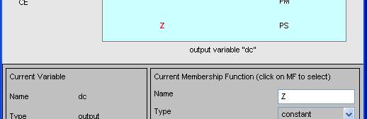
4 65 it is utilized in the present model. The defuzzified output is the duty cycle dc(k). The change in duty cycle dc (k) can be obtained by adding the pervious duty cycle pdc(k) with the duty cycle dc(k) which is given in equation 8. This process stage is called as post processing which is also shown in Figure 4.1. (4.3) Figure 4.2. The input and output fuzzy membership functions are shown in Figure 4.2 Fuzzy memberships used for simulation
5 Rule Table and Inference Engine The control rules that relate the fuzzy output to the fuzzy inputs are derived from general knowledge of the system behavior, also the perception l e (k) is Y, then e(k) and dc(k) respectively. The rule table for the designed fuzzy controller is given in the Tab Table 4.1 Fuzzy rule table for seven membership functions Change in Error Error NB NM NS Z PS PM PB NB NB NB NB NB NM NS Z NM NB NB NB NM NS Z PS NS NB NB NM NS Z PS PM Z NB NM NS Z PS PM PB PS NM NS Z PS PM PB PB PM NS Z PS PM PB PB PB PB Z PS PM PB PB PB PB
6 SIMULATION OF FLC IN MATLAB The detailed design procedure for the development of Fuzzy Logic Controller using MATLAB is given here. As mentioned in the previous section there are three variables chosen, two for input variables Error and Change in Error the third one is for output variable duty cycle. The general procedures to develop the FLC are Step I : Identify the inputs and their ranges and name them Step II : Identify the outputs and their ranges and name them Step III: Create the degree of fuzzy membership function for each input and output Step IV: Construct the rule base that the system will operate under Step V : Decide how the action will be executed by assigning strengths to the rules Step VI: Combine the rules and defuzzify the output Table 4.2 shows the membership function names and ranges of input variable Error. Here Seven triangular membership function were used and ranges between -1 to +1. The triangular membership function is simple and easy to implement. Figurs 4.2 represents the input membership function for Error. The range of membership function shows that the maximum possible normalised speed error is +1 and minimum is -1. This range is possible for controlling the speed of the motor. From many litrerature the seven membership function is the suitable choice of selection and the shape of the membership function is selected.
![68 Linguistic variable for Error Linguistic Value Notation Numerical Value Negative Big NB [-1.333-1 -0.6665] Negative Medium NM [-1-0.6665-0.3334] Negative Small NS [-0.6665-0.3334 0] Zero Z [-0.](/docs-images/81/84558757/images/7-2.jpg "3334 0 0.3334] Positive Small PS [0 0.3334 0.6665] Positive Medium PM [0.3334 0.6665 1] Positive Big PB [0.6665 1 1.334] Figure 4.3 Input membership function for Error")
7 68 Linguistic variable for Error Linguistic Value Notation Numerical Value Negative Big NB [ ] Negative Medium NM [ ] Negative Small NS [ ] Zero Z [ ] Positive Small PS [ ] Positive Medium PM [ ] Positive Big PB [ ] Figure 4.3 Input membership function for Error

![666-1.333 0] Zero Z [-1.333 0 1.333] Positive Small PS [0 1.333 2.666] Positive Medium PM [1.](/docs-images/81/84558757/images/8-2.jpg "333 2.666 4] Positive Big PB [2.666 4 5.334] Figure 4.")
8 69 Linguistic variable for Change in Error Linguistic Value Notation Numerical Value Negative Big NB [ ] Negative Medium NM [ ] Negative Small NS [ ] Zero Z [ ] Positive Small PS [ ] Positive Medium PM [ ] Positive Big PB [ ] Figure 4.4 Input membership function for Change in Error
9 70 Similarly the membership function is chosen for the change in error. The membership function range for change in error is maximum +2 and minimum is -2. Change in error is the difference between present error and previous error. Table 4.3 shows the membership function names and ranges of input variable Cahnge in Error. Figure 4.4 represents the input membership function for Change in Error. Likewise the membership function is chosen for the output variable Table 4.4 shows the membership function names and ranges of output variable Duty Cycle. Figure 4.5 represents the output membership function for Duty Cycle. Figure 4.6 and 4.7 shows the rule viewer and surface viewer of the designed Fuzzy Logic Controller respectively. Linguistic variable for Duty Cycle Linguistic Value Notation Numerical Value Negative Big NB Negative Medium NM Negative Small NS Zero Z 0.00 Positive Small PS 0.33 Positive Medium PM 0.66 Positive Big PB 1.00


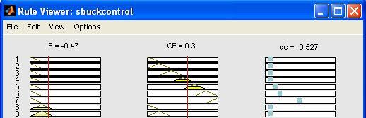
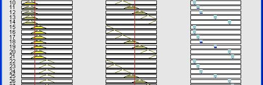

10 71 Figure 4.5. Output membership function for Duty Cycle Figure 4.6 Rule viewer of FLC


11 72 Figure 4.7 Surface viewer of FLC 4.4 SIMULINK MODEL OF THE SYSTEM WITH FUZZY LOGIC CONTROLLER The complete simulation model of the DC series motor drive system with Fuzzy Logic Controller is given in Figure 4.8. The fuzzy controller block from fuzzy logic toolbox is used to test and evaluate the FLC. As mentioned in the PID controller here also the actual speed and the set speed is given to the FLC preprocessing to generate the error and change in error signals. The error and change in error are given as the input to the FLC, the controller produce the duty cycle, during post processing the change in duty cycle is obtained and it is given to the PWM generator unit. The PWM generator unit generates the PWM with the switching frequency of 1KHz by comparing the repeating sequence signal with the FLC output. Then the PWM is given to the current controller, the current controller allows the PWM if the actual motor current is within the limits of the set current value. Further the PWM is given to the DC chopper unit to give the variable DC voltage to the DC series motor. There by the motor speed is controlled.
12 73 Figure 4.8 Simulink Model of DC series motor with FLC The Structure of the fuzzy controller including preprocessing and postprocessing using MATLAB/Simulink is shown in Figure 4.9. In preprocessing stage error is calculated by subtracting the actual speed from the reference speed ref. The error is normalized by dividing with reference speed. The range of normalized speed is from 0 to 1. Then the change in error is calculated from the present error with the previous error using the memory block. The error and change in error is given as input to the FLC through a mux block. The output of the FLC is duty cycle. In postprocessing stage the change in duty cycle is obtained by adding the present duty cycle with previous duty cycle. Figure 4.9 Simulink model of FLC


13 RESULTS AND DISCUSSION FOR THE FLC WITH SEVEN MEMBERSHIP FUNCTION The DC series motor model through the DC-DC converter including FLC was simulated using MATLAB simulation. The fuzzy controller was designed and DC-DC converter fed DC series motor was tested. The simulated waves of gate pulse, output voltage, motor current and speed with respect to time for r=1800 rpm are shown in Figure The expanded view is shown in Figure Figure 4.10 Pulse, Output Voltage, Motor Current and Speed Variation with respect to Time Response for r=1800 rpm
14 75 Figure 4.11 Expanded view of Pulse, Output Voltage, Motor Current and Speed Variation with respect to Time at r=1800 rpm From the Figure 4.11 it is clearly seen that the time duration between each pulse is sec means that the switching frequency is 1 KHz. When the pulse is ON the motor current is increasing and decreasing when the pulse is OFF due to the chopping action of the DC-DC converter. The FLC regulate the speed at 1800 rpm. The performance comparison of developed FLC for DC-DC converter fed 220V DC series motor with PID controller and reported result in Yousef et al (1995) is given in Table 4.5. From the table 4.5 it is seen that all the performance parameter has been reduced considerable amount, which shows that the FLC is superior out of other controllers shown.
15 76 Table 4.5 Performance comparison of developed FLC for 220V DC series motor with rated speed Controller Rise Time (sec) Settling Time (sec) Max. Over Shoot (%) Steady State Error (rpm) Max. Speed Drop (%) Recovery Time (sec) Steady State Error (rpm) Classical PI Yousef et al (1995) Fuzzy Yousef et al (1995) Developed PID During rated speed and 10% load Not mentioned Not mentioned Developed FLC Not mentioned Not mentioned Load Change from 25% to 50% +10 ± Not mentioned Not mentioned +20 ±9


16 77 Figure 4.12 Speed variation for the step change in reference speed at different interval with 10% load torque The Figure 4.12 shows the speed variation and current variation for the step change in reference speed from 500rpm to 1000rpm at 4 sec and 1000rpm to 1800rpm at 7 sec with 10% load torque. The current is always chopping between maximum to minimum. It is seen from figure that when the speed is increased from 500rpm to 1000rpm the motor takes 0.32 sec whereas in the initial stage it took almost 0.35 sec to reach 500rpm. This may be due to the inertia in the beginning. The FLC provides proper speed regulation for all the speed changes. The comparative time domain parameters of Speed variation for various set speed changes are depicted in Table 4.6.
17 78 Table 4.6 Time domain parameter of FLC for different set speed change with 10% load Set Speed Changes 0 to 500rpm 500 to 1000rpm 1000 to 1800rpm Max. Over Shoot (%) Settling Time (sec) The simulated result of speed regulation for a step change in the load torque from 10% to 25%, 25% to 50% and 50% to 100% applied at t=2.5 sec is shown in Figure 4.13, 4.14 and 4.15 respectively. The FLC gives proper response to the system for the load changes from 10% to 100%. At 100% load there is a small dip in the speed response and it is recover the speed with in 1.1 sec. The expanded part of different load changes is given in Figure 4.16 for comparison. The comparative time domain parameters of Speed variation for various load changes are depicted in Table 4.7. Figure 4.13 Speed variation for the step change in load torque from 10% to 25% applied at t=2.5 secs with the speed of 1800 rpm.

18 79 Figure 4.14 Speed variation for the step change in load torque 25% to 50% applied at t=2.5secs with the speed of 1800 rpm. Figure 4.15 Speed variation for the step change in load torque 50% to 100%applied at t=2.5 sec with the speed of 1800 rpm.


19 80 Figure 4.16 Comparison of Speed variation for the step change in load torque applied at t=2.5 sec with rated speed Figure 4.16 provides the comparative analysis for the FLC with various load torque changes. When the load changes from 50% to 100%, the speed variations completely abolished and the speed drop is more than the lesser load conditions. Table 4.7 Time domain parameter of FLC for the load changes for 220V DC Series Motor with rated speed Load Variations 10% to 25% 25% to 50% 50% to 100% Max. Speed Drop (%) Recovery Time (sec) Steady State Error (rpm) ±10 ±9 +3.3
20 81 The Overall time domain parameters of developed PID controller and FLC for 220V DC series motor for rated speed with 10% load, set speed changes and the load torque changes are illustrated in the Table 4.8. From the Table 4.8 it is seen that comparatively the FLC is good in all the aspects. Table 4.8 Overall time domain parameter of developed FLC for 220V DC series motor Controller Developed PID During rated speed and 10% load Developed FLC Rise Time (sec) Settling Time (sec) Max. Over Shoot (%) Steady State Error (rpm) +10 ±2 Set Speed Change from 500 to 1000rpm Max. Over Shoot (%) Settling Time (sec) Load Change from 25% to 50% Max. Speed Drop (%) Recovery Time (sec) Steady State Error (rpm) +20 ±9 4.6 DESIGN OF MODIFIED FUZZY LOGIC CONTROLLER Initially the FLC is designed with seven triangular membership function of equal width and then it was reduced to five of variable width membership function. The width of the membership function is varied in order to reduce the number of membership function from seven to five. In this five membership function, the width of the center membership function is considered to be narrow and it has been wide towards outer.
21 82 Five linguistic variables are used for the input variable e(k) and e(k). That are negative big (NB), negative small (NS), zero (Z), positive small (PS) and positive big (PB). There are many types of membership functions, such as triangular-shaped, Gaussian, sigmoidal, pi-shaped trapezoidal-shaped, bell-shaped etc. the triangular membership function is used for simplicity and also to reduce the calculations. Figure Modified Fuzzy memberships used for simulation In most of the work seven membership functions were preferred for accurate result. In this work only five membership functions were used for the input, error and change in error. To reduce the number of membership
22 83 function the width of the membership functions were kept different. The membership function width for the center membership functions is considered narrow and wide towards outer. The input and output fuzzy membership functions are shown in Figure The rule table for the designed fuzzy controller is given in the Table 4.9. The element in the first row and first column means that If error is NB, and change in error is NB then output is NB. Table 4.9 Fuzzy rule table for five membership functions Change in Error Error NB NS Z PS PB NB NB NB NB NS Z NS NB NB NS Z PS Z NB NS Z PS PB PS NS Z PS PB PB PB Z PS PB PB PB 4.7 RESULTS AND DISCUSSIONS FOR MODIFIED FLC WITH 110V DC SERIES MOTOR The FLC performance was also analyzed in different aspects as in the PID controller analysis in the previous section. In this section the motor parameter for 110V DC series motor is considered for analysis. The same MATLAB/Simulink model shown in Figure 4.8 was utilized to test the performance by replacing the 220V motor model parameter with 110V motor parameter given in Table 3.8. The simulated waves of gate pulse, output voltage, motor current and speed with respect to time for r=1500rpm are shown in Figure The expanded view is shown in Figure 4.19.


23 84 Figure 4.18 Pulse, Output Voltage, Motor Current and Speed Variation with respect to Time Response for r=1500 rpm Figure 4.19 Expanded view of Pulse, Output Voltage, Motor Current and Speed Variation with respect to Time Response for r=1500rpm
24 85 The switching frequency of PWM is 1 KHz. The FLC regulate the speed at 1500rpm. The performance comparison of developed FLC for DC-DC converter fed 110V DC series motor with PID controller is given in Table From the Table 4.10 it is seen that all the value of performance parameters are less for FLC than the PID controller, which shows that the superiority of FLC. Table 4.10 Performance comparison of developed Fuzzy Logic Controller for 110V DC Series Motor with PID controller Controller Developed PID Developed FLC Rise Time (sec) Settling Time (sec) Max. Over Shoot (%) Steady State Error (rpm) Figure 4.20 Speed variation for the step change in reference speed at different interval with 10% load torque
25 86 The Figure 4.20 shows the speed variation for the step change in reference speed from 500rpm to 1000rpm at 3 sec and 1000rpm to 1500 rpm at 7 sec with 10% load torque. It is seen from the Figure 4.20 due to the inertia in the beginning the motor takes 0.36 sec to reach the speed from 0 to 500rpm whereas in the second step it took 0.34 sec only to reach from 500 to 1000rpm. The FLC provides proper speed regulation for all the step speed changes. The comparative time domain parameters of speed variation for various set speed changes are depicted in Table Table 4.11 Time domain parameter of FLC for different set speed change with 10% load Set Speed Changes 0 to 500rpm 500 to 1000rpm 1000 to 1800rpm Max. Over Shoot (%) Settling Time (sec) The simulated result of speed regulation for a step change in the load torque from 10% to 25%, 25% to 50% and 50% to 100% applied at 3 sec, 5.5 sec and 8 sec are shown in Figure The FLC provides proper regulation to the system for the load changes from 10% to 100%. At 100% load the oscillations in speed is eliminated due to high load torque. The comparative time domain parameters of Speed variation for various load changes are represented in Table 4.12.
 0.40 0.46 0.")
26 87 Figure 4.21 Performance of DC series motor with FLC for load variation at 3sec, 5.5sec and 8sec with rated speed Table 4.12 Time domain parameter of FLC for the load changes for 110V DC Series Motor with rated speed Load Variations 10% to 25% 25% to 50% 50% to 100% Max. Speed Drop (%) Recovery Time (sec) Steady State Error (rpm) The Overall time domain parameters of developed PID controller and FLC for 110V DC series motor for rated speed with 10% load, set speed changes and the load torque changes are illustrated in the Table From
27 88 the Table 4.13 it is seen that comparatively the FLC is superior in all the aspects. Table 4.13 Overall time domain parameter of developed FLC for 110V DC series motor Controller Developed PID During rated speed and 10% load Developed FLC Rise Time (sec) Settling Time (sec) Max. Over Shoot (%) Steady State Error (rpm) Set Speed Change from 500 to 1000rpm Max. Over Shoot (%) Settling Time (sec) Load Change from 25% to 50% Max. Speed Drop (%) Recovery Time (sec) Steady State Error (rpm) RESULTS AND DISCUSSIONS FOR MODIFIED FLC WITH DC SEPARATELY EXCITED MOTOR In this section the DC separately excited motor is considered for analysis. Then the same MATLAB/Simulink model shown in Figure 4.8 was utilized to test the performance by replacing the 220V DC series motor model with DC separately excited motor shown in Figure 2.8. The simulated
28 89 waves of speed response with respect to time for Figure r=1800rpm is shown in Figure 4.22 Speed response with respect to time of DC Separately Excited Motor with Fuzzy controller for rated speed and 10% load torque The switching frequency of PWM selected for this case is also the same 1 KHz. The FLC regulate the speed at rated value of 1800rpm. The performance comparison of developed FLC for DC-DC converter fed DC separately excited motor with PID controller for rated condition is given in Table 4.14.
29 90 Table 4.14 Performance comparison of developed FLC for DC Separately Excited Motor Controller Developed PID During rated speed and 10% load Developed FLC Rise Time (sec) Settling Time (sec) Max. Over Shoot (%) Steady State Error (rpm) +23 ±12 Figure 4.23 Speed variation for the step change in reference speed at different interval with 10% load torque

30 91 The Figure 4.23 shows the speed variation for the step change in reference speed from 500rpm to 1000rpm at 4 sec and 1000rpm to 1500rpm at 7 sec with 10% load torque for 220V DC series motor and DC separately excited motor. The modified FLC provides proper speed regulation for all the step speed changes for both the motor. The comparative time domain parameters of speed variation for various set speed changes are depicted in Table Table 4.15 Time domain parameter of FLC for different set speed change with 10% load Set Speed Changes 0 to 500rpm 500 to 1000rpm 1000 to 1800rpm Max. Over Shoot (%) Settling Time (sec) Figure 4.24 Speed variation for the step change in load torque 10% to 25% applied at t=3 sec when the speed is 1800rpm.


31 92 The simulated result of speed regulation for a step change in the load torque from 10% to 25%, 25% to 50% and 50% to 100% applied at 3sec for 220V DC series motor and DC separately excited motor are shown in Figure 4.24, 4.25 and 4.26 respectively. The FLC provides appropriate speed regulation to both DC series and DC separately excited motor for the load changes from 10% to 100%. At 100% load the speed drop of DC series motor is 0.72% and it takes 1.1 sec to recover the original speed where as in DC separately excited motor the speed drop is 0.5%, it is almost equal to speed drop in series motor but it takes 0.18 sec only to recover the speed. While seeing this case the modified FLC is more suited for DC separately excited motor than DC series motor. The comparative time domain parameters of Speed variation for various load changes are represented in Table Figure 4.25 Speed variation for the step change in load torque ( TL=50%) applied at t=3 sec when the speed is 1800rpm.
 1.05 0.77 0.")
32 93 Figure 4.26 Speed variation for the step change in load torque 50% to 100% applied at t=3 sec when the speed is 1800rpm Table 4.16 Time domain parameter of FLC for the load changes for DC separately excited motor with rated speed Load Variations 10% to 25% 25% to 50% 50% to 100% Max. Speed Drop (%) Recovery Time (sec) Steady State Error (rpm)
33 94 The Overall time domain parameters of developed PID controller and FLC for DC separately excited motor for rated speed with 10% load, set speed changes and the load torque changes are illustrated in the Table From the Table 4.17 it is seen that comparatively the FLC is superior in all the aspects than the PID controller. Table 4.17 Overall time domain parameter of developed FLC for DC Separately Excited Motor Controller Developed PID During rated speed and 10% load Developed FLC Rise Time (sec) Settling Time (sec) Max. Over Shoot (%) Steady State Error (rpm) +23 ±12 Set Speed Change from 500 to 1000rpm Max. Over Shoot (%) Settling Time (sec) Load Change from 25% to 50% Max. Speed Drop (%) Recovery Time (sec) Steady State Error (rpm) HARDWARE IMPLEMENTATION WITH FLC The developed modified Fuzzy Logic Controller was implemented by using a NXP 80C51 based microcontroller (P89V51RD2BN). A DC-DC buck converter was built with the MOSFET using IRFP450, and the controllers were tested with DC series motor and DC separately excited
34 95 motor. The speed of the motor was sensed by a pulse type digital speed sensor and to feed back the signal to the controller. The Figure 4.29 shows the experimental setup of the proposed system with DC series motor. The microcontroller (P89V51RD2BN) has an 80C51 compatible core with the following features: 80C51 Central Processing Unit, 5 V Operating voltage from 0 to 40 MHz, 64 kb of on-chip Flash program memory. It also has an PCA (Programmable Counter Array) with PWM and Capture/Compare functions. The PWM is generated at a frequency of 10 khz. A LEM make current sensor LTS25NP is used to sense the motor current and it is compared with the reference current using the comparator LM 399. The AND gate is used to allow the PWM waveform when the actual current is less than the reference current. The PWM from the microcontroller was then amplified for a level through the open collector optocoupler CYN 17-1 and fed to the DC DC power converter through an isolator and driver chip IR2110. The DC-DC buck converter output was given to the DC series motor whose speed is to be controlled. The speed sensor connected to the motor shaft gives the pulse output which again converted in to voltage using f/v converter and this DC voltage is fed to the ADC available in the microcontroller. The implementation of FLC in a microcontroller was done using to develop and compile the C programming for FLC. The C program is compiled and converted into hex file. Finally the hex code was embedded in to the microcontroller used. The hex code is downloaded by using the magic is given in Figure 4.27 and 4.28 respectively.


35 96 Figure 4.27 Screen shot for Keil uvision compiler software Figure 4.28 Screen shot for Flash Magic software to download the hex code
36 97 The Figure 4.29 shows the experimental setup of the system with FLC. The experimental response of the DC series motor and DC separately excited motor for the step change in reference speed are given in Figure 4.30 and 4.31 respectively. Figure 4.29 Hardware setup of the system with FLC Figure 4.30 Experimental graph of speed variation for the step change in reference speed r=1800rpm using fuzzy controller for DC Series Motor
37 98 Figure 4.31 Experimental graph of speed variation for the step change in reference speed r=1800rpm using fuzzy controller for DC Separately Excited Motor Figure 4.30 shows the speed response with the set speed of 1800rpm for Modified FLC controller for DC series motor and Figure 4.31 shows the speed response with the set speed of 1800rpm for Modified FLC controller for DC separately excited motor. From the Figurers it is noted that the DC series motor is taking the settling time of 6 sec and for separately excited motor is 3.2 sec. The modified FLC has produced more oscillations in the response, but it is due to the nature of the FLC. The Table 4.18 exposes the performance comparison of hardware of proposed system with Fuzzy controller.
38 99 Table 4.18 Hardware Performance Comparison of developed FLC with PID controller Controller Settling Time (sec) Max. Over Shoot (%) Steady State Error (rpm) Developed PID controller Series Motor Sep. Ext. Motor Developed FLC Series Motor Sep. Ext. Motor ±17 ± CONCLUSION In this chapter the performance of Fuzzy Logic controller and modified Fuzzy Logic Controller for DC series motor with 220V and 110V motor parameter and DC separately excited motor were analyzed. The performances were analyzed with different load torque and different set speed changes for both DC series and separately excited motor and found that the speed can be controlled effectively with the modified FLC for all the motors. Also in modified FLC the number of membership function is less. Hence the memory required is less during the implementation. The modified FLC reduces the peak overshoot, settling time and steady state error of the system for all the cases. All the response of the system with modified FLC is found to be satisfactory but still it is needed to be reduced the settling time and the speed variations.
CHAPTER 6 NEURO-FUZZY CONTROL OF TWO-STAGE KY BOOST CONVERTER
 73 CHAPTER 6 NEURO-FUZZY CONTROL OF TWO-STAGE KY BOOST CONVERTER 6.1 INTRODUCTION TO NEURO-FUZZY CONTROL The block diagram in Figure 6.1 shows the Neuro-Fuzzy controlling technique employed to control
SIMULATION AND IMPLEMENTATION OF PID-ANN CONTROLLER FOR CHOPPER FED EMBEDDED PMDC MOTOR
 ISSN: 2229-6956(ONLINE) DOI: 10.21917/ijsc.2012.0049 ICTACT JOURNAL ON SOFT COMPUTING, APRIL 2012, VOLUME: 02, ISSUE: 03 SIMULATION AND IMPLEMENTATION OF PID-ANN CONTROLLER FOR CHOPPER FED EMBEDDED PMDC
CHAPTER 4 FUZZY BASED DYNAMIC PWM CONTROL
 47 CHAPTER 4 FUZZY BASED DYNAMIC PWM CONTROL 4.1 INTRODUCTION Passive filters are used to minimize the harmonic components present in the stator voltage and current of the BLDC motor. Based on the design,
Development of a Fuzzy Logic Controller for Industrial Conveyor Systems
 American Journal of Science, Engineering and Technology 217; 2(3): 77-82 http://www.sciencepublishinggroup.com/j/ajset doi: 1.11648/j.ajset.21723.11 Development of a Fuzzy Logic Controller for Industrial
High Efficiency DC/DC Buck-Boost Converters for High Power DC System Using Adaptive Control
 American-Eurasian Journal of Scientific Research 11 (5): 381-389, 2016 ISSN 1818-6785 IDOSI Publications, 2016 DOI: 10.5829/idosi.aejsr.2016.11.5.22957 High Efficiency DC/DC Buck-Boost Converters for High
Speed Control of Three Phase Induction Motor Using Fuzzy-PID Controller
 Speed Control of Three Phase Induction Motor Using Fuzzy-PID Controller Mr. Bidwe Umesh. B. 1, Mr. Shinde Sanjay. M. 2 1 PG Student, Department of Electrical Engg., Govt. College of Engg. Aurangabad (M.S.)
Time Response Analysis of a DC Motor Speed Control with PI and Fuzzy Logic Using LAB View Compact RIO
 Time Response Analysis of a DC Motor Speed Control with PI and Fuzzy Logic Using LAB View Compact RIO B. Udaya Kumar 1, Dr. M. Ramesh Patnaik 2 1 Associate professor, Dept of Electronics and Instrumentation,
CHAPTER 3 METHODOLOGY
 CHAPTER 3 METHODOLOGY 3.1 INTRODUCTION This chapter will explain about the flow chart of project, designing fuzzy logic controller and fuzzy logic algorithms. Next, it will explain electrical circuit design
Modeling & Simulation of PMSM Drives with Fuzzy Logic Controller
 Vol. 3, Issue. 4, Jul - Aug. 2013 pp-2492-2497 ISSN: 2249-6645 Modeling & Simulation of PMSM Drives with Fuzzy Logic Controller Praveen Kumar 1, Anurag Singh Tomer 2 1 (ME Scholar, Department of Electrical
Fuzzy Controllers for Boost DC-DC Converters
 IOSR Journal of Electronics and Communication Engineering (IOSR-JECE) e-issn: 2278-2834,p- ISSN: 2278-8735 PP 12-19 www.iosrjournals.org Fuzzy Controllers for Boost DC-DC Converters Neethu Raj.R 1, Dr.
Pid Plus Fuzzy Logic Controller Based Electronic Load Controller For Self Exited Induction Generator.
 RESEARCH ARTICLE OPEN ACCESS Pid Plus Fuzzy Logic Controller Based Electronic Load Controller For Self Exited Induction Generator. S.Swathi 1, V. Vijaya Kumar Nayak 2, Sowjanya Rani 3,Yellaiah.Ponnam 4
Abstract: PWM Inverters need an internal current feedback loop to maintain desired
 CURRENT REGULATION OF PWM INVERTER USING STATIONARY FRAME REGULATOR B. JUSTUS RABI and Dr.R. ARUMUGAM, Head of the Department of Electrical and Electronics Engineering, Anna University, Chennai 600 025.
Simulation of Fuzzy Controller based Isolated Zeta Converter fed BLDC motor drive
 Simulation of Fuzzy Controller based Isolated Zeta Converter fed BLDC motor drive 1 Sreelakshmi K, 2 Caroline Ann Sam 1 PG Student 2 Asst.Professor 1 EEE Department, 1 Rajagiri School of Engineering and
ISSN: (Online) Volume 2, Issue 1, January 2014 International Journal of Advance Research in Computer Science and Management Studies
 Volume 2, Issue 1, January 2014 International Journal of Advance Research in Computer Science and Management Studies") ISSN: 2321-7782 (Online) Volume 2, Issue 1, January 2014 International Journal of Advance Research in Computer Science and Management Studies Research Paper Available online at: www.ijarcsms.com Fuzzy
ISSN: 2321-7782 (Online) Volume 2, Issue 1, January 2014 International Journal of Advance Research in Computer Science and Management Studies Research Paper Available online at: www.ijarcsms.com Fuzzy
DC Motor Speed Control: A Case between PID Controller and Fuzzy Logic Controller
 DC Motor Speed Control: A Case between PID Controller and Fuzzy Logic Controller Philip A. Adewuyi Mechatronics Engineering Option, Department of Mechanical and Biomedical Engineering, Bells University
Performance Analysis of Fuzzy Logic And PID Controller for PM DC Motor Drive Khalid Al-Mutib 1, N. M. Adamali Shah 2, Ebrahim Mattar 3
 Performance Analysis of Fuzzy Logic And PID Controller for PM DC Motor Drive Khalid Al-Mutib 1, N. M. Adamali Shah 2, Ebrahim Mattar 3 1 King Saud University, Riyadh, Saudi Arabia, muteb@ksu.edu.sa 2 King
SPEED CONTROL OF BRUSHLESS DC MOTOR USING FUZZY BASED CONTROLLERS
 SPEED CONTROL OF BRUSHLESS DC MOTOR USING FUZZY BASED CONTROLLERS Kapil Ghuge 1, Prof. Manish Prajapati 2 Prof. Ashok Kumar Jhala 3 1 M.Tech Scholar, 2 Assistant Professor, 3 Head of Department, R.K.D.F.
A Brushless DC Motor Speed Control By Fuzzy PID Controller
 A Brushless DC Motor Speed Control By Fuzzy PID Controller M D Bhutto, Prof. Ashis Patra Abstract Brushless DC (BLDC) motors are widely used for many industrial applications because of their low volume,
Development of a Fuzzy Logic based Photovoltaic Maximum Power Point Tracking Control System using Boost Converter
 Development of a Fuzzy Logic based Photovoltaic Maximum Power Point Tracking Control System using Boost Converter Triveni K. T. 1, Mala 2, Shambhavi Umesh 3, Vidya M. S. 4, H. N. Suresh 5 1,2,3,4,5 Department
A PLC-based Self-tuning PI-Fuzzy Controller for Linear and Non-linear Drives Control
 A PLC-based Self-tuning PI-Fuzzy Controller for Linear and Non-linear Drives Control Muhammad Arrofiq *1, Nordin Saad *2 Universiti Teknologi PETRONAS Tronoh, Perak, Malaysia muhammad_arrofiq@utp.edu.my
ADVANCES in NATURAL and APPLIED SCIENCES
 ADVANCES in NATURAL and APPLIED SCIENCES ISSN: 1995-0772 Published BYAENSI Publication EISSN: 1998-1090 http://www.aensiweb.com/anas 2017 April 11(4): pages 402-409 Open Access Journal Design and Implementation
Control of DC-DC Buck Boost Converter Output Voltage Using Fuzzy Logic Controller
 International Journal of Control Theory and Applications ISSN : 0974-5572 International Science Press Volume 10 Number 25 2017 Control of DC-DC Buck Boost Converter Output Voltage Using Fuzzy Logic Controller
Performance Improvement of Buck-Boost Converter Using Fuzzy Logic Controller
 International Journal of Engineering Research And Management (IJERM) ISSN : 2349-2058, Volume-04, Issue-10, October 2017 Performance Improvement of Buck-Boost Converter Using Fuzzy Logic Controller B.
Hardware Implementation of Fuzzy Logic Controller for Sensorless Permanent Magnet BLDC Motor Drives
 Hardware Implementation of Fuzzy Logic Controller for Sensorless Permanent Magnet BLDC Motor Drives Mr. Ashish A. Zanjade M.E. Electronics Engineering PIIT, New Panvel,India Prof. (DR) J.W.Bakal S.S. Jondhale
Fuzzy Expert Systems Lecture 9 (Fuzzy Systems Applications) (Fuzzy Control)
 (Fuzzy Control)") Fuzzy Expert Systems Lecture 9 (Fuzzy Systems Applications) (Fuzzy Control) The fuzzy controller design methodology primarily involves distilling human expert knowledge about how to control a system into
Fuzzy Expert Systems Lecture 9 (Fuzzy Systems Applications) (Fuzzy Control) The fuzzy controller design methodology primarily involves distilling human expert knowledge about how to control a system into
Digital Control of MS-150 Modular Position Servo System
 IEEE NECEC Nov. 8, 2007 St. John's NL 1 Digital Control of MS-150 Modular Position Servo System Farid Arvani, Syeda N. Ferdaus, M. Tariq Iqbal Faculty of Engineering, Memorial University of Newfoundland
IMPLEMENTATION OF FUZZY LOGIC SPEED CONTROLLED INDUCTION MOTOR USING PIC MICROCONTROLLER
 Volume 118 No. 24 2018 ISSN: 1314-3395 (on-line version) url: http://www.acadpubl.eu/hub/ http://www.acadpubl.eu/hub/ IMPLEMENTATION OF FUZZY LOGIC SPEED CONTROLLED INDUCTION MOTOR USING PIC MICROCONTROLLER
Comparison of Buck-Boost and CUK Converter Control Using Fuzzy Logic Controller
 ISSN (Online) : 2319-8753 ISSN (Print) : 2347-6710 International Journal of Innovative Research in Science, Engineering and Technology Volume 3, Special Issue 3, March 2014 2014 International Conference
Tuning Of Conventional Pid And Fuzzy Logic Controller Using Different Defuzzification Techniques
 Tuning Of Conventional Pid And Fuzzy Logic Controller Using Different Defuzzification Techniques Afshan Ilyas, Shagufta Jahan, Mohammad Ayyub Abstract:- This paper presents a method for tuning of conventional
High Frequency Soft Switching Boost Converter with Fuzzy Logic Controller
 High Frequency Soft Switching Boost Converter with Fuzzy Logic Controller 1 Anu Vijay, 2 Karthickeyan V, 3 Prathyusha S PG Scholar M.E- Control and Instrumentation Engineering, EEE Department, Anna University
Fuzzy Logic Controller on DC/DC Boost Converter
 21 IEEE International Conference on Power and Energy (PECon21), Nov 29 - Dec 1, 21, Kuala Lumpur, Malaysia Fuzzy Logic Controller on DC/DC Boost Converter N.F Nik Ismail, Member IEEE,Email: nikfasdi@yahoo.com
Speed Control of Brushless DC Motor Using Fuzzy Based Controllers
 Speed Control of Brushless DC Motor Using Fuzzy Based Controllers Harith Mohan 1, Remya K P 2, Gomathy S 3 1 Harith Mohan, P G Scholar, EEE, ASIET Kalady, Kerala, India 2 Remya K P, Lecturer, EEE, ASIET
International Journal of Modern Engineering and Research Technology
 Volume 5, Issue 3, July 2018 ISSN: 2348-8565 (Online) International Journal of Modern Engineering and Research Technology Website: http://www.ijmert.org Modulation of Five Level Inverter Topology for Open
CURRENT FOLLOWER APPROACH BASED PI AND FUZZY LOGIC CONTROLLERS FOR BLDC MOTOR DRIVE SYSTEM FED FROM CUK CONVERTER
 CURRENT FOLLOWER APPROACH BASED PI AND FUZZY LOGIC CONTROLLERS FOR BLDC MOTOR DRIVE SYSTEM FED FROM CUK CONVERTER N. Mohanraj and R. Sankaran Shanmugha Arts, Science, Technology and Research Academy University,
Fuzzy Intelligent Controller for the MPPT of a Photovoltaic Module in comparison with Perturb and Observe algorithm
 Fuzzy Intelligent Controller for the MPPT of a Photovoltaic Module in comparison with Perturb and Observe algorithm B. Amarnath Naidu 1, S. Anil Kumar 2 and Dr. M. Siva Sathya Narayana 3 1, 2 Assistant
Simulation of Synchronous Machine in Stability Study for Power System: Garri Station as a Case Study
 Simulation of Synchronous Machine in Stability Study for Power System: Garri Station as a Case Study Bahar A. Elmahi. Industrial Research & Consultancy Center, baharelmahi@yahoo.com Abstract- This paper
ADJUSTMENT OF PARAMETERS OF PID CONTROLLER USING FUZZY TOOL FOR SPEED CONTROL OF DC MOTOR
 ADJUSTMENT OF PARAMETERS OF PID CONTROLLER USING FUZZY TOOL FOR SPEED CONTROL OF DC MOTOR Raman Chetal 1, Divya Gupta 2 1 Department of Electrical Engineering,Baba Banda Singh Bahadur Engineering College,
Permanent Magnet Brushless DC Motor Control Using Hybrid PI and Fuzzy Logic Controller
 ISSN 39 338 April 8 Permanent Magnet Brushless DC Motor Control Using Hybrid PI and Fuzzy Logic Controller G. Venu S. Tara Kalyani Assistant Professor Professor Dept. of Electrical & Electronics Engg.
A Fuzzy Controlled High Voltage Boosting Converter Based On Boost Inductors and Capacitors
 A Fuzzy Controlled High Voltage Boosting Converter Based On Boost Inductors and Capacitors V.V Jayashankar 1, K.P Elby 2, R Uma 3 ( 1 Dept. of EEE, Sree Narayana Gurukulam College of Engineering, Kolenchery,
CHAPTER 2 PID CONTROLLER BASED CLOSED LOOP CONTROL OF DC DRIVE
 23 CHAPTER 2 PID CONTROLLER BASED CLOSED LOOP CONTROL OF DC DRIVE 2.1 PID CONTROLLER A proportional Integral Derivative controller (PID controller) find its application in industrial control system. It
Resistance Furnace Temperature Control System Based on OPC and MATLAB
 569257MAC0010.1177/0020294015569257Resistance Furnace Temperature Control System Based on and MATLABResistance Furnace Temperature Control System Based on and MATLAB research-article2015 Themed Paper Resistance
CHAPTER 4 FUZZY LOGIC BASED PHOTO VOLTAIC ENERGY SYSTEM USING SEPIC
 56 CHAPTER 4 FUZZY LOGIC BASED PHOTO VOLTAIC ENERGY SYSTEM USING SEPIC 4.1 INTRODUCTION A photovoltaic system is a one type of solar energy system which is designed to supply electricity by using of Photo
Voltage-MPPT Controller Design of Photovolatic Array System Using Fuzzy Logic Controller
 Advances in Energy and Power 2(1): 1-6, 2014 DOI: 10.13189/aep.2014.020101 http://www.hrpub.org Voltage-MPPT Controller Design of Photovolatic Array System Using Fuzzy Logic Controller Faridoon Shabaninia
Control Of Three Phase BLDC Motor Using Fuzzy Logic Controller Anjali. A. R M-Tech in Powerelectronics & Drives,Calicut University
 Control Of Three Phase BLDC Motor Using Fuzzy Logic Controller Anjali. A. R M-Tech in Powerelectronics & Drives,Calicut University Abstract Brushless DC (BLDC) motor drives are becoming widely used in
Fuzzy Logic Based Speed Control System Comparative Study
 Fuzzy Logic Based Speed Control System Comparative Study A.D. Ghorapade Post graduate student Department of Electronics SCOE Pune, India abhijit_ghorapade@rediffmail.com Dr. A.D. Jadhav Professor Department
Comparative Analysis of Room Temperature Controller Using Fuzzy Logic & PID
 Advance in Electronic and Electric Engineering. ISSN 2231-1297, Volume 3, Number 7 (2013), pp. 853-858 Research India Publications http://www.ripublication.com/aeee.htm Comparative Analysis of Room Temperature
Electronic Load Controller for Self Exited Induction Generator Using Fuzzy Logic Controller
 IOSR Journal of Electrical and Electronics Engineering (IOSR-JEEE) e-issn: 2278-1676,p-ISSN: 2320-3331, Volume 5, Issue 3 (Mar. - Apr. 2013), PP 49-54 Electronic Load Controller for Self Exited Induction
A Comparative Study on Speed Control of D.C. Motor using Intelligence Techniques
 International Journal of Electronic and Electrical Engineering. ISSN 0974-2174, Volume 7, Number 4 (2014), pp. 431-436 International Research Publication House http://www.irphouse.com A Comparative Study
CHAPTER 4 CONTROL ALGORITHM FOR PROPOSED H-BRIDGE MULTILEVEL INVERTER
 65 CHAPTER 4 CONTROL ALGORITHM FOR PROPOSED H-BRIDGE MULTILEVEL INVERTER 4.1 INTRODUCTION Many control strategies are available for the control of IMs. The Direct Torque Control (DTC) is one of the most
ANALYSIS OF SEPIC CONVERTER USING PID AND FUZZY LOGIC CONTROLLER
 Impact Factor (SJIF): 5.302 International Journal of Advance Research in Engineering, Science & Technology e-issn: 2393-9877, p-issn: 2394-2444 Volume 5, Issue 3, March-2018 ANALYSIS OF SEPIC CONVERTER
A Novel Fuzzy Control Approach for Modified C- Dump Converter Based BLDC Machine Used In Flywheel Energy Storage System
 A Novel Fuzzy Control Approach for Modified C- Dump Converter Based BLDC Machine Used In Flywheel Energy Storage System B.CHARAN KUMAR 1, K.SHANKER 2 1 P.G. scholar, Dept of EEE, St. MARTIN S ENGG. college,
Design and Implementation of Fuzzy Sliding Mode Controller for Switched Reluctance Motor
 Proceedings of the International MultiConference of Engineers and Computer Scientists 8 Vol II IMECS 8, 9- March, 8, Hong Kong Design and Implementation of Fuzzy Sliding Mode Controller for Switched Reluctance
DC motor position control using fuzzy proportional-derivative controllers with different defuzzification methods
 TJFS: Turkish Journal of Fuzzy Systems (eissn: 1309 1190) An Official Journal of Turkish Fuzzy Systems Association Vol.1, No.1, pp. 36-54, 2010. DC motor position control using fuzzy proportional-derivative
ISSN: [IDSTM-18] Impact Factor: 5.164
![ISSN: [IDSTM-18] Impact Factor: 5.164](/thumbs/94/121360383.jpg "ISSN: [IDSTM-18] Impact Factor: 5.164") IJESRT INTERNATIONAL JOURNAL OF ENGINEERING SCIENCES & RESEARCH TECHNOLOGY SPEED CONTROL OF DC MOTOR USING FUZZY LOGIC CONTROLLER Pradeep Kumar 1, Ajay Chhillar 2 & Vipin Saini 3 1 Research scholar in
IJESRT INTERNATIONAL JOURNAL OF ENGINEERING SCIENCES & RESEARCH TECHNOLOGY SPEED CONTROL OF DC MOTOR USING FUZZY LOGIC CONTROLLER Pradeep Kumar 1, Ajay Chhillar 2 & Vipin Saini 3 1 Research scholar in
P. Sivakumar* 1 and V. Rajasekaran 2
 IJESC: Vol. 4, No. 1, January-June 2012, pp. 1 5 P. Sivakumar* 1 and V. Rajasekaran 2 Abstract: This project describes the design a controller for PWM boost Rectifier. This regulates the output voltage
Fuzzy Logic Techniques Applied to the Control of a Three-Phase Induction Motor
 Fuzzy Logic Techniques Applied to the Control of a ThreePhase Induction Motor João L. Afonso Jaime Fonseca Júlio S. Martins Carlos A. Couto Department of Industrial Electronics University of Minho 4800
CHAPTER 7 HARDWARE IMPLEMENTATION
 168 CHAPTER 7 HARDWARE IMPLEMENTATION 7.1 OVERVIEW In the previous chapters discussed about the design and simulation of Discrete controller for ZVS Buck, Interleaved Boost, Buck-Boost, Double Frequency
Application of Fuzzy Logic Controller in Shunt Active Power Filter
 IJIRST International Journal for Innovative Research in Science & Technology Volume 2 Issue 11 April 2016 ISSN (online): 2349-6010 Application of Fuzzy Logic Controller in Shunt Active Power Filter Ketan
South Asian Journal of Engineering and Technology Vol.3, No.3 (2017)
") ISSN No: 2454-9614 Speed Control of BLDC Motor using Fuzzy Logic and PID Controller Fed Electric Vehicle Mohammad Fasil PK, M.Pradeep, R.Sathish Kumar, G.Ranjhitha, M.Valan RajKumar Department of Electrical
ISSN No: 2454-9614 Speed Control of BLDC Motor using Fuzzy Logic and PID Controller Fed Electric Vehicle Mohammad Fasil PK, M.Pradeep, R.Sathish Kumar, G.Ranjhitha, M.Valan RajKumar Department of Electrical
CHAPTER-III MODELING AND IMPLEMENTATION OF PMBLDC MOTOR DRIVE
 CHAPTER-III MODELING AND IMPLEMENTATION OF PMBLDC MOTOR DRIVE 3.1 GENERAL The PMBLDC motors used in low power applications (up to 5kW) are fed from a single-phase AC source through a diode bridge rectifier
Fuzzy Logic Based Speed Control System for Three- Phase Induction Motor
 ANALELE UNIVERSITĂłII EFTIMIE MURGU REŞIłA ANUL XX, NR. 1, 2013, ISSN 1453-7397 Marwan A. Badran, Mostafa A. Hamood, Waleed F. Faris Fuzzy Logic Based Speed Control System for Three- Phase Induction Motor
Speed control of a DC motor using Controllers
 Automation, Control and Intelligent Systems 2014; 2(6-1): 1-9 Published online November 20, 2014 (http://www.sciencepublishinggroup.com/j/acis) doi: 10.11648/j.acis.s.2014020601.11 ISSN: 2328-5583 (Print);
ANALYSIS OF V/f CONTROL OF INDUCTION MOTOR USING CONVENTIONAL CONTROLLERS AND FUZZY LOGIC CONTROLLER
 ANALYSIS OF V/f CONTROL OF INDUCTION MOTOR USING CONVENTIONAL CONTROLLERS AND FUZZY LOGIC CONTROLLER Archana G C 1 and Reema N 2 1 PG Student [Electrical Machines], Department of EEE, Sree Buddha College
Design of an Intelligent Pressure Control System Based on the Fuzzy Self-tuning PID Controller
 Design of an Intelligent Pressure Control System Based on the Fuzzy Self-tuning PID Controller 1 Deepa S. Bhandare, 2 N. R.Kulkarni 1,2 Department of Electrical Engineering, Modern College of Engineering,
CHAPTER 4 PI CONTROLLER BASED LCL RESONANT CONVERTER
 61 CHAPTER 4 PI CONTROLLER BASED LCL RESONANT CONVERTER This Chapter deals with the procedure of embedding PI controller in the ARM processor LPC2148. The error signal which is generated from the reference
Chapter 6 ACTIVE CLAMP ZVS FLYBACK CONVERTER WITH OUTPUT VOLTAGE DOULER
 185 Chapter 6 ACTIVE CLAMP ZVS FLYBACK CONVERTER WITH OUTPUT VOLTAGE DOULER S. No. Name of the Sub-Title Page No. 6.1 Introduction 186 6.2 Single output Active Clamped ZVS Flyback Converter 186 6.3 Active
ADVANCES in NATURAL and APPLIED SCIENCES
 ADVANCES in NATURAL and APPLIED SCIENCES ISSN: 1995-0772 Published BYAENSI Publication EISSN: 1998-1090 http://www.aensiweb.com/anas 2017 Special 11(5): pages 129-137 Open Access Journal Comparison of
A CONTROL STRATEGY TO STABILIZE PWM DC-DC BUCK CONVERTER WITH INPUT FILTER USING FUZZY-PI AND ITS COMPARISON USING PI AND FUZZY CONTROLLERS
 A CONTROL STRATEGY TO STABILIZE PWM DC-DC BUCK CONVERTER WITH INPUT FILTER USING FUZZY-PI AND ITS COMPARISON USING PI AND FUZZY CONTROLLERS 1 CH.SUSILA, 2 B.RAJASEKHAR 1 Post Graduation student (Control
A GENERALIZED DIRECT APPROACH FOR DESIGNING FUZZY LOGIC CONTROLLERS IN MATLAB/SIMULINK GUI ENVIRONMENT
 A GENERALIZED DIRECT APPROACH FOR DESIGNING FUZZY LOGIC CONTROLLERS IN MATLAB/SIMULINK GUI ENVIRONMENT Ismail H. ALTAS 1, Adel M. SHARAF 2 1 Department of Electrical and Electronics Engineering Karadeniz
Fuzzy Logic Controlled Solar Module for Driving Three- Phase Induction Motor
 IOP Conference Series: Materials Science and Engineering PAPER OPEN ACCESS Fuzzy Logic Controlled Solar Module for Driving Three- Phase Induction Motor To cite this article: Nurul Afiqah Zainal et al 2016
Comparative Study of PID and Fuzzy Controllers for Speed Control of DC Motor
 Comparative Study of PID and Fuzzy Controllers for Speed Control of DC Motor Osama Omer Adam Mohammed 1, Dr. Awadalla Taifor Ali 2 P.G. Student, Department of Control Engineering, Faculty of Engineering,
II. L-Z SOURCE INVERTER
 V/F Speed Control of Induction Motor by using L- Z Source Inverter Priyanka A. Jadhav 1, Amruta A. Patil 2, Punam P. Patil 3, Supriya S. Yadav 4, Rupali S. Patil 5, Renu C. Lohana 6 1,2,3,4,5,6 Electrical
Bi-Directional Dc-Dc converter Drive with PI and Fuzzy Logic Controller
 Bi-Directional Dc-Dc converter Drive with PI and Fuzzy Logic Controller A.Uma Siva Jyothi 1, D S Phani Gopal 2,G.Ramu 3 M.Tech Student Scholar, Power Electronics, Department of Electrical and Electronics,
Sensorless Control of BLDC Motor Drive Fed by Isolated DC-DC Converter
 Sensorless Control of BLDC Motor Drive Fed by Isolated DC-DC Converter Sonia Sunny, Rajesh K PG Student, Department of EEE, Rajiv Gandhi Institute of Technology, Kottayam, India 1 Asst. Prof, Department
A PID Controller for Real-Time DC Motor Speed Control using the C505C Microcontroller
 A PID Controller for Real-Time DC Motor Speed Control using the C505C Microcontroller Sukumar Kamalasadan Division of Engineering and Computer Technology University of West Florida, Pensacola, FL, 32513
Implementation of Fuzzy Controller to Magnetic Levitation System
 IX Control Instrumentation System Conference (CISCON - 2012), 16-17 November 2012 201 Implementation of Fuzzy Controller to Magnetic Levitation System Amit Kumar Choudhary, S.K. Nagar and J.P. Tiwari Abstract---
OPTIMAL TORQUE RIPPLE CONTROL OF ASYNCHRONOUS DRIVE USING INTELLIGENT CONTROLLERS
 OPTIMAL TORQUE RIPPLE CONTROL OF ASYNCHRONOUS DRIE USING INTELLIGENT CONTROLLERS J.N.Chandra Sekhar 1 and Dr.G. Marutheswar 2 1 Department of EEE, Assistant Professor, S University College of Engineering,
CHAPTER 5 CONTROL SYSTEM DESIGN FOR UPFC
 90 CHAPTER 5 CONTROL SYSTEM DESIGN FOR UPFC 5.1 INTRODUCTION This chapter deals with the performance comparison between a closed loop and open loop UPFC system on the aspects of power quality. The UPFC
Design and implementation of Open & Close Loop Speed control of Three Phase Induction Motor Using PI Controller
 Design and implementation of Open & Close Loop Speed control of Three Phase Induction Motor Using PI Controller Ibtisam Naveed 1, Adnan Sabir 2 1 (Electrical Engineering, NFC institute of Engineering and
6. HARDWARE PROTOTYPE AND EXPERIMENTAL RESULTS
 6. HARDWARE PROTOTYPE AND EXPERIMENTAL RESULTS Laboratory based hardware prototype is developed for the z-source inverter based conversion set up in line with control system designed, simulated and discussed
CHAPTER 3 APPLICATION OF THE CIRCUIT MODEL FOR PHOTOVOLTAIC ENERGY CONVERSION SYSTEM
 63 CHAPTER 3 APPLICATION OF THE CIRCUIT MODEL FOR PHOTOVOLTAIC ENERGY CONVERSION SYSTEM 3.1 INTRODUCTION The power output of the PV module varies with the irradiation and the temperature and the output
Closed loop performance investigation of various controllers based chopper fed DC drive in marine applications
 Indian Journal of Geo Marine Sciences Vol. 46 (5), May 217, pp. 144-151 Closed loop performance investigation of various s based chopper fed DC drive in marine applications S.Selvaperumal *, P.Nedumal
Fuzzy Logic Based Position-Sensorless Speed Control of Multi Level Inverter Fed PMBLDC Drive
 52 JOURNAL OF ADVANCES IN INFORMATION TECHNOLOGY, VOL. 1, NO. 1, FEBRUARY 2010 Fuzzy Logic Based Position-Sensorless Speed Control of Multi Level Inverter Fed PMBLDC Drive Narmadha T.V. Research Scholar,
ADVANCES in NATURAL and APPLIED SCIENCES
 ADVANCES in NATURAL and APPLIED SCIENCES ISSN: 1995-0772 Published BY AENSI Publication EISSN: 1998-1090 http://www.aensiweb.com/anas 2015 Special; 9(17): pages Open Access Journal Real Time Implementation
CHAPTER 6 DEVELOPMENT OF A CONTROL ALGORITHM FOR BUCK AND BOOST DC-DC CONVERTERS USING DSP
 115 CHAPTER 6 DEVELOPMENT OF A CONTROL ALGORITHM FOR BUCK AND BOOST DC-DC CONVERTERS USING DSP 6.1 INTRODUCTION Digital control of a power converter is becoming more and more common in industry today because
Australian Journal of Basic and Applied Sciences. Performance Evaluation of Three-Phase Inverter with Various Fuzzy Logic Controllers
 AENSI Journals Australian Journal of Basic and Applied Sciences ISSN:1991-8178 Journal home page: www.ajbasweb.com Performance Evaluation of Three-Phase Inverter with Various Fuzzy Logic Controllers A.M.
CHAPTER 4 AN EFFICIENT ANFIS BASED SELF TUNING OF PI CONTROLLER FOR CURRENT HARMONIC MITIGATION
 92 CHAPTER 4 AN EFFICIENT ANFIS BASED SELF TUNING OF PI CONTROLLER FOR CURRENT HARMONIC MITIGATION 4.1 OVERVIEW OF PI CONTROLLER Proportional Integral (PI) controllers have been developed due to the unique
SIMULINK MODELING OF FUZZY CONTROLLER FOR CANE LEVEL CONTROLLING
 International Journal of Industrial Engineering & Technology (IJIET) ISSN 2277-4769 Vol. 3, Issue 1, Mar 2013, 43-50 TJPRC Pvt. Ltd. SIMULINK MODELING OF FUZZY CONTROLLER FOR CANE LEVEL CONTROLLING YOGESH
DSPACE BASED FUZZY LOGIC CONTROLLED BOOST CONVERTER
 36 DSPACE BASED FUZZY OGIC CONTOED BOOST CONVETE İbrahim SEFA, Necmi ATIN, Şaban ÖZDEMİ Department of Electrical Education, Faculty of Technical Education, GEMEC Group, Gazi University, 06500 Besevler,
DESIGN AND SIMULATION OF DIFFERENT CONTROLLERS FOR SPEED CONTROL OF CHOPPER FED DC MOTOR
 DESIGN AND SIMULATION OF DIFFERENT CONTROLLERS FOR SPEED CONTROL OF CHOPPER FED DC MOTOR JYOTI PRAKASH RANA (109EE0299) SUMAN JAIN (109EE0273) Department of Electrical Engineering National Institute of
PERFORMANCE STUDIES OF INTEGRATED FUZZY LOGIC CONTROLLER FOR BRUSHLESS DC MOTOR DRIVES USING ADVANCED SIMULATION MODEL
 ISSN: 2229-6956(ONLINE) DOI: 10.21917/ijsc.2011.0039 ICTACT JOURNAL ON SOFT COMPUTING: SPECIAL ISSUE ON FUZZY IN INDUSTRIAL AND PROCESS AUTOMATION, JULY 2011, VOLUME: 02, ISSUE: 01 PERFORMANCE STUDIES
CHAPTER 6 ANALYSIS OF THREE PHASE HYBRID SCHEME WITH VIENNA RECTIFIER USING PV ARRAY AND WIND DRIVEN INDUCTION GENERATORS
 73 CHAPTER 6 ANALYSIS OF THREE PHASE HYBRID SCHEME WITH VIENNA RECTIFIER USING PV ARRAY AND WIND DRIVEN INDUCTION GENERATORS 6.1 INTRODUCTION Hybrid distributed generators are gaining prominence over the
CHAPTER 6 OPTIMIZING SWITCHING ANGLES OF SRM
 111 CHAPTER 6 OPTIMIZING SWITCHING ANGLES OF SRM 6.1 INTRODUCTION SRM drives suffer from the disadvantage of having a low power factor. This is caused by the special and salient structure, and operational
IJESRT. Scientific Journal Impact Factor: (ISRA), Impact Factor: 1.852
, Impact Factor: 1.852") IJESRT INTERNATIONAL JOURNAL OF ENGINEERING SCIENCES & RESEARCH TECHNOLOGY Design of Self-tuning PID controller using Fuzzy Logic for Level Process P D Aditya Karthik *1, J Supriyanka 2 *1, 2 Department
IJESRT INTERNATIONAL JOURNAL OF ENGINEERING SCIENCES & RESEARCH TECHNOLOGY Design of Self-tuning PID controller using Fuzzy Logic for Level Process P D Aditya Karthik *1, J Supriyanka 2 *1, 2 Department
Fuzzy Logic Controlled PV Powered Buck Converter with MPPT
 Fuzzy Logic Controlled PV Powered Buck Converter with MPPT Dr.Bos Mathew Jos 1, Abhijith S 2.Aswin Venugopal 3, Basil Roy 4, Dhanesh R 5 Associate Professor, Dept. of EEE, Mar Athanasius College of Engineering,
Fuzzy Based Control Using Lab view For Temperature Process
 Fuzzy Based Control Using Lab view For Temperature Process 1 S.Kavitha, 2 B.Chinthamani, 3 S.Joshibha Ponmalar 1 Assistant Professor, Dept of EEE, Saveetha Engineering College Tamilnadu, India 2 Assistant
CHAPTER 3 WAVELET TRANSFORM BASED CONTROLLER FOR INDUCTION MOTOR DRIVES
 49 CHAPTER 3 WAVELET TRANSFORM BASED CONTROLLER FOR INDUCTION MOTOR DRIVES 3.1 INTRODUCTION The wavelet transform is a very popular tool for signal processing and analysis. It is widely used for the analysis
A Performance Study of PI controller and Fuzzy logic controller in V/f Control of Three Phase Induction Motor Using Space Vector Modulation
 A Performance Study of PI controller and Fuzzy logic controller in V/f Control of Three Phase Induction Motor Using Space Vector Modulation Safdar Fasal T K & Unnikrishnan L Department of Electrical and
Simulation of Optimal Speed Control for a DC Motor Using Conventional PID Controller and Fuzzy Logic Controller
 International Journal of Information and Computation Technology. ISSN 0974-2239 Volume 3, Number 3 (2013), pp. 181-188 International Research Publications House http://www. irphouse.com /ijict.htm Simulation
CHAPTER 4 ON LINE LOAD FREQUENCY CONTROL
 CHAPTER 4 ON LINE LOAD FREQUENCY CONTROL The main objective of Automatic Load Frequency Control (LFC) is to maintain the frequency and active power change over lines at their scheduled values. As frequency