Owner s Manual 取扱説明書
|
|
|
- Elfreda Matthews
- 5 years ago
- Views:
Transcription
1 Owner s Manual
2
3 Owner s Manual Before using this product, carefully read the sections entitled: USING THE UNIT SAFELY and IMPORTANT NOTES (p. 4; p. 6). These sections provide important information concerning the proper operation of the product. Additionally, in order to feel assured that you have gained a good grasp of every feature provided by your new product, Owner s Manual should be read in its entirety. The manual should be saved and kept on hand as a convenient reference. Copyright 2008 ROLAND CORPORATION All rights reserved. No part of this publication may be reproduced in any form without the written permission of ROLAND CORPORATION.
4 USING THE UNIT SAFELY Used for instructions intended to alert the user to the risk of death or severe injury should the unit be used improperly. Used for instructions intended to alert the user to the risk of injury or material damage should the unit be used improperly. * Material damage refers to damage or other adverse effects caused with respect to the home and all its furnishings, as well to domestic animals or pets. The symbol alerts the user to important instructions or warnings.the specific meaning of the symbol is determined by the design contained within the triangle. In the case of the symbol at left, it is used for general cautions, warnings, or alerts to danger. The symbol alerts the user to items that must never be carried out (are forbidden). The specific thing that must not be done is indicated by the design contained within the circle. In the case of the symbol at left, it means that the unit must never be disassembled. The symbol alerts the user to things that must be carried out. The specific thing that must be done is indicated by the design contained within the circle. In the case of the symbol at left, it means that the powercord plug must be unplugged from the outlet. 4
5 Do not open or perform any internal modifications on the product.... Do not open or perform any internal modifications on the product. (The only exception would be where this manual provides specific instructions which should be followed in order to put in place user-installable options; see p. 8.)... Do not attempt to repair the product, or replace parts within it (except when this manual provides specific instructions directing you to do so). Refer all servicing to your retailer, the nearest Roland Service Center, or an authorized Roland distributor, as listed on the Information page.... Never use or store the product in places that are: Subject to temperature extremes (e.g., direct sunlight in an enclosed vehicle, near a heating duct, on top of heat-generating equipment); or are Damp (e.g., baths, washrooms, on wet floors); or are Humid; or are Exposed to rain; or are Dusty; or are Subject to high levels of vibration.... In households with small children, an adult should provide supervision until the child is capable of following all the rules essential for the safe operation of the product.... Protect the product from strong impact. (Do not drop it!)... Before installing the ARX-01, you must first always turn off the unit (Fantom-G6/G7/G8) and unplug its power cord. Install the circuit board only into the specified unit (Fantom-G6/G7/ G8). Remove only the specified screws during the installation.... 5
6 IMPORTANT NOTES When you purchase the ARX-01 SuperNATURAL Expansion Board from an authorized Roland dealer, the included sounds and samples are licensed, not sold, to you by Roland Corporation, for commercial use in music production, public performance, broadcast, etc. You may use any of the included phrases and/or samples in a commercial or non-commercial recording without paying any additional license fees. However, you must strictly adhere to the following crediting guidelines on any music recording that utilize material from ARX-01. Reproduction or duplication of this collection or any of the sound recording contained in the ARX-01, either as they exist on this expansion board or by any means of reformatting, mixing, filtering, re-synthesizing, processing or otherwise editing for use in another product or for re-sale, is strictly prohibited without the express written consent of Roland. All unauthorized giving, trading, lending, renting, re-issue, redistribution or re-sale of the sounds included in the ARX-01 are expressly prohibited. In Plain English: Be creative in your application of the ARX-01 sounds, and keep this library for your use only. DO NOT COPY IT. Roland constantly monitors other Soundware releases to check for copyright infringements, and will prosecute all piracy and copyright violations to the fullest extent of the law. THIS LIBRARY IS GUARANTEED TO BE 100% COPYRIGHT CLEAN. Placement This device may interfere with radio and television reception. Do not use this device in the vicinity of such receivers. Additional Precautions To avoid disturbing your neighbors, try to keep the product s volume at reasonable levels (especially when it is late at night). When you need to transport the product, package it in the box (including padding) that it came in, if possible. Otherwise, you will need to use equivalent packaging materials. * In the interest of product improvement, the specifications and/or appearance of this product are subject to change without prior notice. 6
7 Contents USING THE UNIT SAFELY...4 IMPORTANT NOTES...6 Installing the expansion board in your product... 8 Installation in your product...8 Confirmation after installation...11 To remove the board from the product...12 Installation de la carte d expansion dans un appareil.13 Installer la carte dans un appareil...13 Retirer la carte de l appareil...16 Introduction...17 Main Features...17 ARX series SuperNATURAL expansion boards Roland SuperNATURAL Technology ARX-01 Drums The structure of ARX-01 Drums...18 Creating a Kit...19 The basic screen...19 Selecting a kit Group Fader Saving a kit (on the Fantom-G) Selecting a Tone (Tone screen)...21 Tone Settings...22 Customizing a tone (Tone/Customize screen)...22 Flam/Roll settings (Tone/Flam/Roll screen)...24 Volume change and tone adjustments (Tone/Comp/ screen)...26 Volume adjustment (Tone/Output screen)...27 Adjusting the volume balance of the tones (Mixer screen)...28 Applying effects (Effects/Routing screen)...28 Multi-effect settings (Effects/MFX screen)...29 Multi-effect control (Effects/MFX Ctrl screen)...29 Setting of Reverb (Effects/Reverb screen)...31 Choking/muting the drum sound (Ctrl screen)...32 Initializing a Kit/Tone or copying a Tone (Utility screen)...33 Initializing a kit or tone...33 Copying a tone...33 Multi-Effects List Multi-Effects Types...34 Multi-Effects Parameters...35 About the STEP RESET function...66 About Note...67 Specifications Index
8 Installing the expansion board in your product Cautions when installing Before you install this expansion board (hereafter referred to as the board ), you should carefully read the procedure for installing expansion boards given in the owner s manual of the product in which you re installing it. To avoid the risk of damage to internal components that can be caused by static electricity, please carefully observe the following whenever you handle the board. Before you touch the board, always first grasp a metal object (such as a water pipe), so you are sure that any static electricity you might have been carrying has been discharged. When handling the board, grasp it only by its edges. Avoid touching any of the electronic components or connectors. Save the bag in which the board was originally shipped, and put the board back into it whenever you need to store or transport it. Do not touch any of the printed circuit pathways or connection terminals. Never use excessive force when installing a circuit board. If it doesn t fit properly on the first attempt, remove the board and try again. When you ve finished installing the expansion board, follow the steps described in the owner s manual of your device to verify that the board was installed correctly. Installation in your product 1. As described in your product s owner s manual, expose the slot in which the expansion board is to be installed. 2. Orient the board with the slot of your product as shown in the illustration. Slot of the product Latched holders Board (expansion board) Roland logo Non-latched holders Holes that engage the non-latched holders 8
9 3. Insert the board into the product s non-latched board holders until you hear a click. 4. Gently lower the board into place. Connector of board Connector of product Align board s holes with holders Board Non-latched holders 9
10 5. From above, press down on the board at the three locations indicated in the illustration until the latched board holders lock into place. 6. Verify that the latched board holders are locked. Edge of the board where the logo is affixed Near the cutouts in the board 7. Return the expansion board installation slot to its original state. 10
11 Confirmation after installation After you ve finished installing the expansion board, you will need to perform the following procedure to confirm the installation. This installation procedure needs to be performed only the first time you power up your device after installing the expansion board. 1. Power up your device as described in its owner s manual. 2. If the expansion board was installed correctly, an installation confirmation screen will appear. Press [F8 (Execute)] button to begin installation. If the installation confirmation screen does not appear the first time you power up after installing the expansion board, it is likely that the board was not installed correctly. Check once again to make sure that the board is correctly installed. It may take five to ten minutes before installation is finished. Never turn off the power during this installation process. 3. When you see the Power Off screen indicating that installation is finished, switch your device s power off, then on again as described in its owner s manual. * The screen shown here is for when the board is installed in the Fantom-G. This completes the expansion board installation process. 11
12 To remove the board from the product 1. As described in your product s owner s manual, expose the slot in which the expansion board was installed. 3. Verify that the two latched board holders are unlocked, then gently pull up the board and disconnect the connector. 2. Unlatch the latched board holders. 4. Disengage the board from the non-latched board holders, and remove the board. 12
13 Installation de la carte d expansion dans un appareil Mises en garde relatives à l installation Avant d installer cette carte d expansion (la carte), il faut lire attentivement la procédure d installation des cartes d expansion décrite dans le guide d utilisation de l appareil dans lequel la carte sera installée. Veuillez suivre attentivement les instructions suivantes quand vous manipulez la carte afin d éviter toutrisque d endommagement des pièces internes par l électricité statique. Toujours toucher un objet métallique relié à la terre (comme un tuyau par exemple) avant de manipuler la carte pour vous décharger de l électricité statique que vous auriez pu accumuler. Lorsque vous manipulez la carte, la tenir par les côtés. Évitez de toucher aux composants ou aux connecteurs. Conservez le sachet d origine dans lequel était la carte lors de l envoi et remettez la carte dedans si vous devez la ranger ou la transporter. Ne pas toucher aux circuits imprimés ou aux connecteurs. Ne jamais forcer lors de l installation de la carte de circuits imprimés. Si la carte s ajuste mal au premier essai, enlevez la carte et recommencez l installation. Une fois la carte installée, il faut suivre la procédure décrite dans le guide d utilisation pour vérifier que la carte est installée correctement. Installer la carte dans un appareil 1. Suivre les instructions données dans le guide d utilisation de l appareil pour dégager la fente où la carte d expansion doit être installée. 2. Orienter la carte de façon à ce qu elle s aligne avec la vente de l appareil, comme le montre l illustration. Fente de l appareil Supports bloqués Carte (carte d expansion) Logo Roland Supports non bloqués Trous de retenue des supports non bloqués 13
14 3. Insérer la carte dans les supports non bloqués jusqu à ce qu un clic se fasse entendre. 4. Abaisser la carte délicatement. Connecteur de la carte Connecteur de l appareil Aligner les trous de la carte et les supports Carte Supports non bloqués 14
15 5. Appuyer sur la carte aux trois points indiqués sur l illustration jusqu à ce que les supports se bloquent en place. 6. S assurer que les supports de carte sont bien bloqués. Bord de la carte où se trouve le logo Près des découpes de la carte 7. Suivre les instructions données dans le guide d utilisation et vérifier que la carte d expansion est installée correctement. 15
16 Retirer la carte de l appareil 1. Suivre les instructions données dans le guide d utilisation de l appareil pour dégager la fente où la carte d expansion a été installée. 3. Vérifier que les deux supports de carte sont débloqués puis tirer délicatement sur la carte et déconnecter le connecteur. 2. Débloquer les supports de carte. 4. Retirer la carte des supports débloqués, et la retirer ensuite complètement. 16
17 Introduction Main Features ARX series SuperNATURAL expansion boards The ARX series SuperNATURAL expansion boards represent a further evolution for Roland s line of expansion solutions, which began with the SR-JV80 series and SRX series -they are a completely new type of expansion board. SuperNATURAL technology delivers natural, richly expressive sounds and effects along with a dedicated graphic user interface, all adding up to a comprehensive application environment that allows an unprecedented degree of expressive playability and customization. Roland SuperNATURAL Technology Proprietary Roland sound generation technology that realistically reproduces the tonal changes and performance techniques distinctive of an acoustic instrument, allowing you to perform music that is natural and richly expressive. ARX-01 Drums SuperNATURAL technology provides powerful drum customizing The SuperNATURAL technology featured in the ARX-01 allows aggressive customization of the drum sounds. You can change the depth of the shell, the diameter of a cymbal, the position of the mic, or even the muffling (muting), giving you the same degree of customization that you have over an acoustic drum. Customizing the drum sound is easy, and does not require specialized knowledge. A graphical user interface allows you to edit intuitively while watching the screen. In contrast to the way in which you choose a drum sound on a conventional PCM synthesizer or sampler, this new technology lets you work more creatively to make a drum kit that s just right for your song. From acoustic drum sounds that cover the full range of musical styles to the sounds of vintage gear, such as the ever-popular TR-808/909, numerous presets are provided, giving you a powerful array of resources to create drum parts for your productions. Effects that can be set independently for each tone, and powerful mixing functionality Up to twenty-four different tones can be assigned to a single kit. A compressor and equalizer are provided for each tone. There s also a 24-channel mixer that lets you make detailed volume and pan settings 17
18 18 for each tone, in addition to a multi-effect and a reverb. Using just the ARX-01, you can construct drum parts that are at a level that s comparable to those used by recording studios. The structure of ARX-01 Drums Basic structure ARX series SuperNATURAL expansion boards can receive performance data and control data from devices that are compatible with the ARX series, and produce an appropriate stereo audio signal in response. * ARX series boards support up to 16 parts, but the ARX-01 Drums board is designed to produce only one part. Tones A tone is the smallest unit of sound on the ARX-01 Drums board. A tone corresponds to one of the individual instruments (e.g., bass drum or cymbal) that makes up a drum set. Each tone is provided with COMP (compressor) and (equalizer). You can also make settings such as Roll or Flam for each tone. * You can t change the correspondence between note numbers and tones. Kits A group of twenty-four tones is called a Kit. A kit is provided with MFX (multi-effect) and reverb. The twenty-four tones are assigned to note numbers 34 (B 1) through 57 (A3). The ARX-01 Drums board contains fifty kits. If the board is installed in a Fantom-G, kit data is saved in the Fantom- G project. from ARX compatible device (Performance data) KIT 01 KIT 50 TONE 24 (Note No.57) Tone 1 (Note No.34) INST Type Tuning MIC Position : MIXER COMP/ REVERB ARX-01 Drums MFX to ARX compatible device (Audio signal)
19 Creating a Kit About this manual The screen images used in this manual are taken from a Fantom-G with the ARX-01 installed. The various procedures described also assume that you are using the ARX-01 installed in a Fantom-G. For details on how to move the cursor or edit a value, refer to the owner s manual for the device in which you ve actually installed the ARX-01. The basic screen fig eps The basic screen shows the KIT NAME, twenty-four indicators that represent the Current Tone (p. 21), and the group faders. When the basic screen is displayed, you can also assign a name to the kit and save it. Selecting a kit Move the cursor to KIT NAME and change the value to select a kit ( ). Group Fader Eight faders are shown in the basic screen of the ARX-01. These are called the Group Faders. You can divide the twenty-four tones among eight groups, and use these group faders to adjust the volume of the groups. To assign each tone to a group, use the Tone screen s Fader Group settings (p. 21). 19
20 Saving a kit (on the Fantom-G) A kit you ve created is temporary; it will be lost if you select a different kit. If you want to save the kit you ve edited, proceed as follows. 1. Press [WRITE] on the Fantom-G. 2. Assign a name to the kit. For details on how to assign a name, refer to the Fantom-G owner s manual. fig eps 3. When you ve finished assigning the name, press [F8 (OK)] button. 4. Select a kit number, and press [F8 (WRITE)] button. 5. When the confirmation screen appears, press [F7 (OK)] button to save the kit. 20
21 Selecting a Tone (Tone screen) In the Tone screen you can select the tones that make up the kit. * The Mute Switch in this screen is linked with the Mute Sw (p. 27) of the Tone/Output screen. * The Comp Switch in this screen is linked with the Comp Sw (p. 26) of the Tone/ Comp/ screen. When the Tone screen is displayed, you can switch the Current Tone by playing a key. Parameter Value Description Current Tone Tone 01 Tone 24 Indicates the tone number of the currently displayed tone. To select a tone, change this value. Parameter Value Description Inst Type KICK, SNARE, TOM, HIHAT, RIDE, CYMBAL, OTHER, E.KICK, E.SNARE, E.TOM, Selects the type of instrument. E.HIHAT, E.RIDE, E.CYMBAL, E.OTHER Inst Number (Depends on the Inst Type ) Selects a variation of the instrument. Fader Group 1 8 Assigns the tone to a fader group. Layer Tone OFF, Tone 01 Tone 24 Mute Group 0(OFF), 1 24 Assign Type MULTI, SINGLE If you want the current tone to sound simultaneously with another tone, specify the number of that tone. If there is a combination of tones that should not sound simultaneously, such as an open hi-hat sound and a closed hi-hat sound, set the Mute Group parameter of those tones to the same number. Mute Group is a function that prevents tones of the same setting from being heard together. If you don t want to use this function, set this to 0. This specifies how the tone will sound when played repeatedly. MULTI: The same tone will be sounded on top of the already-sounding tone. If you repeatedly play a slowdecaying sound such as a cymbal, the new note will not silence the previous note. SINGLE: The currently sounding note will be silenced before the new note is played. 21
22 Customizing a tone (Tone/Customize screen) fig eps KICK, SNARE, TOM Tone Settings Parameter Value Shell Depth Head Tuning Muffling 0 3 Mic Position Buzz HIHAT, RIDE, CYMBAL Parameter Size Sustain Value In the Tone/Customize screen you can adjust the sound in the same ways as on an acoustic drum; for example, by choosing the desired shell depth, and by installing muffling (muting). The customizable parameters vary depending on the instrument type to which the tone belongs. OTHER Parameter Pitch Sustain E.KICK Parameter Tune Attack Level Decay Cutoff Resonance Value Value 22
23 E.SNARE Parameter Tune Tone Attack Level Snpy Decay Cutoff Resonance Value E.TOM, E.HIHAT, E.RIDE, E.OTHER Parameter Tune Decay Cutoff Resonance Value E.CYMBAL Parameter Tune Tone Decay Cutoff Resonance Value 23
24 Flam/Roll settings (Tone/Flam/Roll screen) fig eps Flam-related parameters fig.flam.eps Velocity Rate Rate Offset Note On Time Last Note (Velocity = Note On) Here you can apply a fram or roll effect to each tone. You can use note velocity to switch the flam or roll effect on/off. Parameter Value Description Flam/Roll Velocity Threshold Flam/Roll Type Upper Flam/Roll Type Lower Boundary between Upper and Lower OFF, FLAM, ROLL OFF, FLAM, ROLL Selects the way in which the tone will sound when the note velocity is above the Velocity Threshold setting. At OFF, the tone sounds in the normal way. Selects the way in which the tone will sound when the note velocity is below the Velocity Threshold setting. At OFF, the tone sounds in the normal way. Parameter Value Description Rate 1 100, note Time interval between flam notes Offset Difference in strength between note and flam note(s) Flam Time 1 16 Number of flam notes Time Velocity Sens Feel 0 32 Change in the number of flam notes in response to velocity. With a positive (+) setting, velocity will increase the number of flam notes; with a negative setting (-), velocity will decrease the number of flam notes. Amount of random change in the strength of flam notes and their time interval For details on the note that can be selected for the Rate parameter, refer to About Note (p. 67) 24
25 fig.roll.eps Roll-related parameters Delay Rate Rate Velocity Curve Offset Time Note On 2nd Note Parameter Value Description Rate 1 100, note Time interval between roll notes Delay Time interval until roll notes begin Offset Curve Roll Time 1 16 Number of roll notes Time Velocity Sens Feel 0 32 Difference in strength between note on and the first roll note Change in the strength of the roll notes. With a positive (+) setting, the roll notes will become stronger; with a negative (-) setting, the roll notes will become weaker. Change in the number of roll notes in response to velocity. With a positive (+) setting, velocity will increase the number of roll notes; with a negative setting (-), velocity will decrease the number of roll notes. Amount of random change in the strength of roll notes and their time interval 25
26 Volume change and tone adjustments (Tone/Comp/ screen) fig eps Compressor-related parameters Parameter Value Description Comp Sw ON/OFF Compressor on/off Input Level Volume level that is input to the compressor Attack ms Time from when the input exceeds the threshold until compression begins Release ms Time from when the input falls below the threshold until compression is turned off Output Gain db Level of the output sound Threshold Level above which compression is applied Ratio 1:1 :1 Compression ratio -related parameters Here you can adjust the compressor and equalizer for each tone. * The Tone Level in this screen is linked with the Tone Level parameter of the Tone/Output screen (p. 27). Compressor This reduces high levels and boosts low levels, making the overall volume more consistent. Parameter Value Description Low Freq Hz Frequency of the low range Low Gain db Gain of the low frequency range High Freq Hz Frequency of the high range High Gain db Gain of the high frequency range 26
27 Volume adjustment (Tone/Output screen) fig.signal-flow.eps Here you can make settings related to the output of each tone. Signal Flow Inst Pan Input Level Tone Output Level Level COMP/ Reverb Send Level Output Assign MFX to MFX to Mixer DRY to Reverb Parameter Value Description Pan L R Tone Level Output Level Output Assign Reverb Send Level DRY, MFX Adjusts the pan of the tone. L64 places the sound at far left, 0 at the center, and 63R at the far right. Specifies the volume of the tone. You ll use this parameter mainly to adjust the volume balance relative to the other tones. Specifies the signal level of each tone. Selects whether each tone will output its original sound or will use MFX. DRY: The original sound will be output without processing. MFX: The sound will be sent through the multi-effect before being output. Specifies the level of the signal sent from each tone to reverb. Mute Sw ON/OFF Turns muting on/off for each tone. 27
28 Adjusting the volume balance of the tones (Mixer screen) fig eps Applying effects (Effects/Routing screen) In the Effects/Routing screen you can make settings for multi-effect (MFX) and reverb. Here you can specify each tone s Comp Sw (p. 26), Mute Sw (p. 27), Reverb Send Level (p. 27), Pan (p. 27), Tone Level (p. 27), and gain (p. 26). Parameter Value Description MFX Type 0(THRU), 1 47 MFX Output Level MFX Reverb Send Level Reverb Type Reverb Level (OFF), 1(REVERB), 2(SRV ROOM), 3(SRV HALL), 4(SRV PLATE) Selects the multi-effect type. For details on each type, refer to Multi-Effects List (p. 34) Specifies the volume of the sound that has passed through the multi-effect. Specifies the amount of reverb applied to the sound that has passed through the multi-effect. Choose 0 if you don t want to apply reverb. Selects the type of reverb. For details on each type, refer to Setting of Reverb (Effects/Reverb screen) (p. 31) Specifies the volume of the sound that has passed through the reverb. 28
29 Multi-effect settings (Effects/MFX screen) In the Effects/MFX screen you can set the parameters of the multieffect. In this screen you can edit the parameters of the multi-effect you selected in MFX Type (p. 29). For details on the parameters that can be edited, refer to Multi-Effects List (p. 34). Parameter Value Description MFX Type 0(THRU), 1 47 Control Assign 1 4 (Depends on the MFX Type ) Selects the type of multi-effect. For details on each type, refer to Multi-Effects List (p. 34). Multi-effect control lets you use MIDI messages to control the parameters of the multi-effect. For details, refer to Multi-effect control (Effects/MFX Ctrl screen) (p. 29). For details on Control Assign 1 4, refer to Multi-effect control (Effects/MFX Ctrl screen) (p. 29). Multi-effect control (Effects/MFX Ctrl screen) In order to control parameters such as the volume of the multi-effect or the delay time of a delay from an external MIDI device, you will normally need to transmit MIDI system exclusive messages, which are a type of MIDI message that is specific to a particular device. However, system exclusive message settings are complex, and these messages will also increase the amount of data that needs to be transmitted. Thus, this expansion board allows you to use MIDI messages such as control changes to control the most important multi-effect parameters. For example, you can use the pitch bend lever to vary the depth of distortion, or use your keyboard playing touch to change the delay time. The parameters that can be controlled in this way are preassigned for each multi-effect type. The parameters that are assigned for each multi-effect type are marked with a # in the list of Multi- Effects Parameters (p. 35). This ability to use MIDI messages to vary the multi-effect parameters in real time is called multi-effect control. The ARX-01 expansion board allows you to use four multi-effect controls simultaneously. To use multi-effect control, you need to specify the MIDI message (Source 1 4) that will control the desired parameter (Control Assign 1 4) in the specified way (Sens 1 4). 29
30 MFX Control Source 1 4 Value OFF CC01 31, 32(OFF), PITCH BEND AFTERTOUCH AUDIO Description Multi-effect control will not be used. Control Change. Pitch Bend. Afttertouch. Volume level that is input to the Multi-effect. MFX Control Sens 1 4 Specifies the depth to which multi-effect control will affect the parameter. Choose a positive (+) value if you want to modify the parameter from its current value toward the positive direction (higher value, toward the right, faster, etc.). Choose a negative (-) value if you want to modify the parameter from its current value toward the negative direction (lower value, toward the left, slower, etc.). With both positive (+) and negative (-) settings, the greater the number, the greater the change. Choose 0 if you don t want to modify the parameter. Value:
31 Setting of Reverb (Effects/Reverb screen) In the Effects/Reverb screen you can set the parameters of the reverb. Parameter Value Description Type Type: 1 (REVERB) Type Time HF Damp 0 (OFF), 1 (REVERB), 2 (SRV ROOM), 3 (SRV HALL), 4 (SRV PLATE) ROOM1, ROOM2, STAGE1, STAGE2, HALL1, HALL2, DELAY, PAN-DELAY Hz, BYPASS Type of reverb Type of reverb/delay ROOM1: short reverb with high density ROOM2: short reverb with low density STAGE1: reverb with greater late reverberation STAGE2: reverb with strong early reflections HALL1: very clear-sounding reverb HALL2: rich reverb DELAY: conventional delay effect PAN-DELAY: delay effect with echoes that pan left and right Time length of reverberation(type: ROOM1.HALL2) Delay time(type: DELAY, PAN-DELAY) Adjusts the frequency above which the highfrequency content of the reverb sound will be cut, or damped. If you do not want to cut the high frequencies, set this parameter to BYPASS. Parameter Value Description Delay Feedback Type:2(SRV ROOM)/3(SRV HALL)/4(SRV PLATE) Adjusts the amount of delay feedback when the Type setting is DELAY or PAN-DE- LAY. Pre Delay ms Adjusts the delay time from the direct sound until the reverb sound is heard. Time Time length of reverberation Size 1 8 Size of the simulated room or hall High Cut 160 Hz 12.5 khz, BYPASS Adjusts the frequency above which the highfrequency content of the reverb will be reduced. If you do not want to reduce the high frequencies, set this parameter to BYPASS. Density Density of reverb Diffusion Adjusts the change in the density of the reverb over time. The higher the value, the more the density increases with time. (The effect of this setting is most pronounced with long reverb times.) LF Damp Freq Hz Adjusts the frequency below which the lowfrequency content of the reverb sound will be reduced, or damped. LF Damp Gain HF Damp Freq HF Damp Gain db 4000 Hz 12.5 khz db Adjusts the amount of damping applied to the frequency range selected with LF Damp. With a setting of 0, there will be no reduction of the reverb s low-frequency content. Adjusts the frequency above which the highfrequency content of the reverb sound will be reduced, or damped. Adjusts the amount of damping applied to the frequency range selected with HF Damp. With a setting of 0, there will be no reduction of the reverb s high-frequency content. 31
32 Choking/muting the drum sound (Ctrl screen) Note number 58 (B 3) is assigned the Choke/Mute function; by pressing this key, you can stop the sound of certain types of instrument that are currently sounding. In the Ctrl screen you can specify the instrument that will be choked/ muted. * The manner of muting will depend on the velocity. A low velocity will mute the sound gradually, while a strong velocity will mute the sound quickly. Parameter Value Description Mute Key Type OFF, HHT, RID, CYM, RID-CYM, HHT-RID-CYM, ALL Specify the type of instrument that will be choked/muted. OFF: The Choke/Mute function will not be used. HHT: The hi-hat sound will be muted. RID: The ride sound will be muted. CYM: The cymbal sound will be muted. RID-CYM: Ride and cymbal sound will be muted. HHT-RID-CYM: Hi-hat, ride and cymbal sound will be muted. ALL: All sound will be muted. 32
33 Initializing a Kit/Tone or copying a Tone (Utility screen) In the Utility screen you can initialize kits or tones, or copy the settings of a tone to a different tone. Initializing a kit or tone This operation lets you return the settings of the current kit or current tone to their default values. Kit Init will initialize the settings of the current kit. Tone Init will initialize the settings of the current tone. 1. Select the kit or tone that you want to initialize. 2. In the Utility screen, choose Kit Init or Tone Init. 3. When the confirmation screen appears, press [F7 (OK)] button. If you decide to cancel, press [F8 (EXIT)] button. * If you ve installed the ARX-01 in a Fantom-G6/G7/G8, executing a Factory Reset for the Fantom-G6/G7/G8 will reset the expansion boards to their factory-set condition. Copying a tone This operation lets you copy the settings of a tone to a different tone of the currently selected kit. Making good use of this operation will help you create kits efficiently. 1. Select the tone that you want to copy. 2. In the Utility screen, choose Tone Copy. The Tone Copy screen will appear. 3. Choose the "Destination (copy-destination)" tone number. 4. Press [F8 (Execute)] button. A confirmation message will appear. 5. Press [F7 (OK)] button to execute the copy. If you decide to cancel, press [F8 (EXIT)] button. 33
34 Multi-Effects List Multi-Effects Types There are 47 types of multi-effect. FILTER (9 types) 01 STEREO p SPECTRUM p ENHANCER p ISOLATOR p LOW BOOST p SUPER FILTER p STEP FILTER p AUTO WAH p HUMANIZER p. 40 MODULATION (7 types) 10 PHASER p STEREO PHASER p STEP PHASER p RING MODULATOR p TREMOLO p AUTO PAN p ROTARY p. 44 CHORUS (6 types) 17 HEXA-CHORUS p TREMOLO CHORUS p SPACE-D p STEREO CHORUS p STEREO FLANGER p STEP FLANGER p. 48 DYNAMICS (7 types) 23 OVERDRIVE p DISTORTION p GUITAR AMP SIMULATOR p STEREO COMPRESSOR p STEREO LIMITER p SLICER p GATE p. 52 LOFI (6 types) 30 LOFI NOISE p LOFI COMPRESS p LOFI RADIO p TELEPHONE p PHONOGRAPH p TAPE ECHO p. 56 PITCH (2 types) 36 FBK PITCH SHIFTER p Vo PITCH SHIFTER p. 58 REVERB (1 type) 38 GATED REVERB p. 58 DELAY (9 types) 39 STEREO DELAY p MODULATION DELAY p TRIPLE TAP DELAY p QUADRUPLE TAP DELAY p MULTI TAP DELAY p REVERSE DELAY p SHUFFLE DELAY p TIME CONTROL DELAY p TIME SKIP DELAY p
35 Multi-Effects Parameters 01: STEREO (Stereo Equalizer) This is a four-band stereo equalizer (low, mid x 2, high). fig.mfx01 4-Band Each multi-effect has Control Assign parameters. These indicate the parameters that can be controlled via Multi-effect control (Effects/MFX Ctrl screen) (p. 29). 4-Band For details on the note that can be selected for some parameter, refer to About Note (p. 67) In the parameter list below, an indication of #1 #4 follows the name of parameters that are selected for Control Assign by default. Parameter Value Description Low Freq 200, 400 Hz Frequency of the low range Low Gain # db Gain of the low frequency range High Freq 2000, 4000, 8000 Hz Frequency of the high range High Gain # db Gain of the high frequency range Mid1 Freq Hz Frequency of Middle Range 1 Mid1 Q 0.5, 1.0, 2.0, 4.0, 8.0 Width of Middle Range 1 Select a higher Q value to narrow Middle Range 1. Mid1 Gain # db Gain of Middle Range 1 Mid2 Freq Hz Frequency of Middle Range 2 Mid2 Q 0.5, 1.0, 2.0, 4.0, 8.0 Width of Middle Range 2 Select a higher Q value to narrow Middle Range 2. Mid2 Gain # db Gain of Middle Range 2 Level Output level 35
36 02: SPECTRUM This is a type of filter that modifies the timbre by boosting or cutting the level of specific frequencies. It is similar to an equalizer, but has eight frequency points fixed at locations most useful for adding character to the sound. Q fig.mfx02 Pan Spectrum Parameter Value Description 0.5, 1.0, 2.0, 4.0, 8.0 L64 63R Pan L Pan R Simultaneously adjusts the width of the adjusted ranges for all of the frequency bands. Stereo location of the SPECTRUM output Level Output level Band 1 (250 Hz) Band 2 (500 Hz) #1 Band 3 (1 khz) #2 Band 4 (1.25 khz) Gain of each frequency band db * This can be set using the sliders of Band 5 (2 khz) #3 the part mixer. Band 6 (3.15 khz) Band 7 (4 khz) #4 Band 8 (8kHz) 03: ENHANCER Controls the overtone structure of the high frequencies, adding sparkle and brightness to the sound. fig.mfx03 Enhancer Enhancer Mix Mix Parameter Value Description Sens # Sensitivity of the enhancer Mixl # Level of the overtones generated by the enhancer Low Gain db Gain of the low frequency range of frequencies High Gain db Gain of the high frequency range of frequencies Level Output level 36
37 04: ISOLATOR This is an equalizer that radically cuts the volume of selected frequencies, allowing you to create special effects cutting the volume in various ranges. fig.mfx04 Parameter Value Description Boost/Cut High #3 Boost/Cut Middle #2 Boost/Cut Low #1 AntiPhase Middle Sw AntiPhase Middle Level Isolator Isolator db OFF, ON Low Boost Low Boost These boost and cut each of the High, Middle, and Low frequency ranges. At -60 db, the sound becomes inaudible. 0 db is equivalent to the input level of the sound. Settings of the Anti-Phase function for the Middle frequency ranges. When turned on, a stereo copy of the sound is phase-inverted and added to the signal. Adjusts the level settings for the Middle frequency ranges. Adjusting this level for certain frequencies allows you to lend emphasis to specific elements within a sound. (This is effective only for stereo source.) Anti Phase Low Sw OFF, ON Settings of the Anti-Phase function for the Middle frequency ranges Anti Phase Low The parameters are the same as for the Middle Level frequency ranges. Turns Low Booster on/off. Low Boost Sw OFF, ON This emphasizes the bottom frequencies to create a heavy bass sound. Increasing this value gives you a heavier low end. Low Boost Level * Depending on the Isolator and filter settings, this effect may be hard to hear. Level Output level 05: LOW BOOST Boosts the volume of the lower range, creating powerful lows. fig.mfx05 Parameter Value Description Boost Frequency #1 Boost Gain #2 Boost Width #3 Low Boost Low Boost Hz 0 12 db WIDE, MID, NAR- ROW Center frequency at which the lower range will be boosted Amount by which the lower range will be boosted Width of the lower range that will be boosted Low Gain db Gain of the low frequency range High Gain db Gain of the high frequency range Level Output level 37
38 06: SUPER FILTER This is a filter with an extremely sharp slope. The cutoff frequency can be varied cyclically. fig.mfx06 Super Filter Super Filter Parameter Value Description Rate Hz, note Rate of modulation Depth Depth of modulation Attack Speed at which the cutoff frequency will change This is effective if Modulation Wave is SQR, SAW1, or SAW2. Level Output level Parameter Value Description Filter Type #1 Filter Slope Filter Cutoff #2 Filter Resonance #3 LPF, BPF, HPF, NOTCH -12, -24, -36 db Filter type Frequency range that will pass through each filter LPF: frequencies below the cutoff BPF: frequencies in the region of the cutoff HPF: frequencies above the cutoff NOTCH: frequencies other than the region of the cutoff Amount of attenuation per octave -36 db: extremely steep -24 db: steep -12 db: gentle Cutoff frequency of the filter Increasing this value will raise the cutoff frequency. Filter resonance level Increasing this value will emphasize the region near the cutoff frequency. Filter Gain # db Amount of boost for the filter output Modulation Sw OFF,ON On/off switch for cyclic change Modulation Wave TRI, SQU, SIN, SAW1, SAW2 How the cutoff frequency will be modulated TRI: triangle wave SQR: square wave SIN: sine wave SAW1: sawtooth wave (upward) SAW2: sawtooth wave (downward) 38
39 07: STEP FILTER This is a filter whose cutoff frequency can be modulated in steps. You can specify the pattern by which the cutoff frequency will change. fig.mfx07 Step Filter 08: AUTO WAH A filter that turns on and off to create a cyclical change in timbre. fig.mfx08 Auto Wah Step Filter Rate #1 Parameter Value Description Attack Filter Type #2 Filter Slope Filter Resonance # Hz, note LPF, BPF, HPF, NOTCH -12, -24, -36 db Rate of modulation Speed at which the cutoff frequency changes between steps Filter type Frequency range that will pass through each filter LPF: frequencies below the cutoff BPF: frequencies in the region of the cutoff HPF: frequencies above the cutoff NOTCH: frequencies other than the region of the cutoff Amount of attenuation per octave -12 db: gentle -24 db: steep -36 db: extremely steep Filter resonance level Increasing this value will emphasize the region near the cutoff frequency. Filter Gain # db Amount of boost for the filter output Level Output level Step Cutoff frequency at each step Parameter Value Description Filter Type LPF, BPF Type of filter LPF: The wah effect is applied over a wide frequency range. BPF: The wah effect is applied over a narrow frequency range Rate # Hz, Frequency of modulation note Depth # Depth of modulation Sens Adjusts the sensitivity with which the filter is controlled. Manual # Adjusts the center frequency at which the effect is applied. Peak # Adjusts the amount of the wah effect that occurs in the range of the center frequency. Set a higher value for Q to narrow the range to be affected. Level Output level 39
40 09: HUMANIZER Adds a vowel character to the sound, making it similar to a human voice. fig.mfx09 Parameter Value Description Drive Sw OFF, ON Turns Drive on/off. Drive Degree of distortion Also changes the volume. Vowel1 #1 a, e, i, o, u Vowel2 #2 a, e, i, o, u Selects the vowel. Rate # Hz, Frequency at which the two vowels note switch Depth Effect depth Input Sync Sw Overdrive OFF, ON Formant Pan L Pan R Determines whether the LFO for switching the vowels is reset by the input signal (ON) or not (OFF). Input Sync Threshold Volume level at which reset is applied Manual # Point at which Vowel 1/2 switch 49 or less: Vowel 1 will have a longer duration. 50: Vowel 1 and 2 will be of equal duration. 51 or more: Vowel 2 will have a longer duration. Low Gain db Gain of the low frequency range High Gain db Gain of the high frequency range Pan L64 63R Stereo location of the output Level Output level 10: PHASER Adds a phase-shifted sound to the original sound, producing a swirling modulation that creates spaciousness and depth. fig.mfx10 Phaser Resonance Parameter Value Description Manual # Adjusts the basic frequency at which the sound will be modulated. Rate # Hz, note Frequency of modulation Depth # Depth of modulation Resonance # Amount of feedback Mix Level of the phase-shifted sound Pan L64 63R Stereo location of the PHASEput Level Output Level Mix Pan L Pan R 40
41 11:STEREO PHASER This is a stereo phaser. fig.mfx11 12:STEP PHASER With the Step effects, you can also make stepped changes in the pitch of sounds to which the Phaser effect is applied. fig.mfx12 Phaser Phaser Mix Mix Step Phaser Step Phaser Mix Mix Parameter Value Description Mode 4, 8 stage Number of stages in the phaser Polarity INVERSE, SYNCHRO Selects whether the left and right phase of the modulation are the same or opposite each other. INVERSE: The left and right phase are opposite. When using a mono source, this spreads the sound in stereo. SYNCHRO: The left and right phase are the same. Select this when working with a stereo source. Rate # Hz, note Frequency of modulation Depth # Depth of modulation Manual # Adjusts the basic frequency from which the sound is modulated. Resonance # Amount of feedback Cross Feedback % Adjusts the amount of the phaser sound that s fed back into the effect. Negative (- ) settings invert the phase. Mix Level of the phase-shifted sound Low Gain db Gain of the low frequency range High Gain db Gain of the high frequency range Level Output level Parameter Value Description Mode 4, 8 stage Number of stages in the phaser Polarity INVERSE, SYNCHRO Selects whether the left and right phase of the modulation are the same or opposite each other. INVERSE: The left and right phase are opposite. When using a mono source, this spreads the sound in stereo. SYNCHRO: The left and right phase are the same. Select this when working with a stereo source. Rate # Hz, note Frequency of modulation Depth Depth of modulation Manual # Adjusts the basic frequency from which the sound is modulated. Resonance # Amount of feedback Cross Feedback Step Rate # % Hz, note Adjusts the amount of the phaser sound that s fed back into the effect. Negative (-) settings invert the phase. Rate of pitch change 41
42 Parameter Value Description Mix Level of the phase-shifted sound Low Gain db Gain of the low frequency range High Gain db Gain of the high frequency range Level Output level 13: RING MODULATOR This is an effect that applies amplitude modulation (AM) to the input signal, producing bell-like sounds. You can also change the modulation frequency in response to changes in the volume of the sound sent into the effect. fig.mfx13 Ring Mod Ring Mod Parameter Value Description Frequency # Adjusts the frequency at which modulation is applied. Sens # Adjusts the amount of frequency modulation applied. Polarity UP, DOWN Determines whether the frequency modulation moves towards higher frequencies (UP) or lower frequencies (DOWN). Low Gain db Gain of the low frequency range High Gain db Gain of the high frequency range Balance #3 D100:0W D0:100W Level Output level Volume balance between the direct sound (D) and the effect sound (W) 42
43 14: TREMOLO Cyclically modulates the volume to add tremolo to the sound. fig.mfx14 15: AUTO PAN Cyclically modulates the stereo location of the sound. fig.mfx15 Tremolo Auto Pan Tremolo Auto Pan Parameter Value Description Modulation Wave #1 TRI, SQR, SIN, SAW1, SAW2 Modulation Wave TRI: triangle wave SQR: square wave SIN: sine wave SAW1: sawtooth wave (upward) SAW2: sawtooth wave (downward) Rate # Hz, note Frequency of the change Depth # Depth to which the effect is applied Low Gain db Gain of the low frequency range High Gain db Gain of the high frequency range Level Output level Parameter Value Description Modulation Wave #1 TRI, SQR, SIN, SAW1, SAW2 Modulation Wave TRI: triangle wave SQR: square wave SIN: sine wave SAW1: sawtooth wave (upward) SAW2: sawtooth wave (downward) Rate # Hz, note Frequency of the change Depth # Depth to which the effect is applied Low Gain db Gain of the low frequency range High Gain db Gain of the high frequency range Level Output level 43
44 16: ROTARY The Rotary effect simulates the sound of the rotary speakers often used with the classic electric organs. Since the movement of the high-range and lowrange rotors can be set independently, the unique characteristics of these speakers can be simulated quite accurately. This effect is most suitable for electric organ Patches. Parameter Value Description Woofer Level Volume of the low frequency rotor Separation Stereo width of the sound Level # Output level fig.mfx16 Rotary Parameter Value Description Tweeter Slow Rate #1 Woofer Slow Rate #2 Tweeter Fast Rate #3 Woofer Fast Rate #4 Speed Tweeter Acceleration Woofer Acceleration Hz Hz Hz Hz SLOW, FAST Slow speed (SLOW) of the high-frequency rotor Slow speed (SLOW) of the low-frequency rotor Fast speed (FAST) of the high-frequency rotor Fast speed (FAST) of the low-frequency rotor Simultaneously switches the rotational speed of the low frequency rotor and high frequency rotor. SLOW: Slows down the speed to the Slow Rate. FAST: Speeds up the speed to the Fast Rate. Adjusts the time it takes the high frequency rotor to reach the newly selected speed when switching between fast and slow speeds. Adjusts the time it takes the low frequency rotor to reach the newly selected speed when switching between fast and slow speeds. Tweeter Level Volume of the high frequency rotor 44
45 17: HEXA-CHORUS Uses a six-phase chorus (six layers of chorused sound) to give richness and spaciousness to the sound. fig.mfx17 Parameter Value Description Pre Delay ms Adjusts the time until chorusing is heard. Rate # Hz, note Frequency of modulation Depth # Depth of modulation Pre Delay Deviation Depth Deviation Pan Deviation Balance # D100:0W D0:100W Hexa Chorus Level Output level Adjusts the differences in Pre Delay between each chorus layer. Adjusts the difference in modulation depth between each chorus layer. Adjusts the difference in stereo location between each chorus layer. 0: All chorus layers are in the center. 20: The chorus layers are spaced at 60- degree intervals relative to the center. Volume balance between the direct sound (D) and the chorus sound (W) 18: TREMOLO CHORUS This is a chorus effect with added Tremolo (cyclic modulation of volume). fig.mfx18 Parameter Value Description Pre Delay ms Adjusts the time until the chorus sound is heard. Chorus Rate Hz, note Modulation frequency of the chorus effect Chorus Depth Modulation depth of the chorus effect Tremolo Rate #1 Tremolo Separation Tremolo Phase Balance # Hz, note Modulation frequency of the tremolo effect Spread of the tremolo effect deg Phase of the tremolo effect D100:0W D0:100W Tremolo Chorus Level Output level Volume balance between the direct sound (D) and the tremolo chorus sound (W) 45
46 19: SPACE-D This is a multiple chorus that applies two-phase modulation in stereo. It creates no audible modulation, yet produces a transparent chorus effect. fig.mfx19 Space D 20: STEREO CHORUS This is a stereo chorus. A filter is provided so that you can adjust the timbre of the chorused sound. fig.mfx20 Chorus Space D Chorus Parameter Value Description Pre Delay ms Adjusts the time until the chorus sound is heard. Rate # Hz, note Frequency of modulation Depth # Depth of modulation Phase deg Spatial spread of the sound Low Gain db Gain of the low frequency range High Gain db Gain of the high frequency range Balance #3 D100:0W D0:100W Level Output level Volume balance between the direct sound (D) and the chorus sound (W) Parameter Value Description Filter Type OFF, LPF, HPF Type of filter OFF: no filter is used LPF: cuts the frequency range above the Cutoff Freq HPF: cuts the frequency range below the Cutoff Freq Cutoff Freq Hz Basic frequency of the filter Pre Delay ms Adjusts the time until the chorus sound is heard. Rate # Hz, note Frequency of modulation Depth # Depth of modulation Phase deg Spatial spread of the sound Low Gain db Gain of the low frequency range High Gain db Gain of the high frequency range Balance #3 D100:0W D0:100W Level Output level Volume balance between the direct sound (D) and the chorus sound (W) 46
47 21: STEREO FLANGER This is a stereo flanger. It produces a metallic resonance that rises and falls somewhat like a jet airplane taking off or landing. A filter is provided so that you can adjust the timbre of the flanged sound. fig.mfx21 Flanger Flanger Feedback Feedback Parameter Value Description Low Gain db Gain of the low frequency range High Gain db Gain of the high frequency range Balance #4 D100:0W D0:100W Level Output level Volume balance between the direct sound (D) and the flanger sound (W) Parameter Value Description Filter Type Cutoff Freq Pre Delay Rate #1 OFF, LPF, HPF Hz ms Hz, note Type of filter OFF: no filter is used LPF: cuts the frequency range above the Cutoff Freq HPF: cuts the frequency range below the Cutoff Freq Basic frequency of the filter Adjusts the time until the flanger sound is heard. Frequency of modulation Depth # Depth of modulation Phase deg Spatial spread of the sound Feedback # % Adjusts the amount of the flanger sound that s fed back into the effect. Negative (- ) settings invert the phase. 47
48 22: STEP FLANGER This is a flanger in which the flanger pitch changes in steps. The speed at which the pitch changes can also be specified in terms of a note value based on a specified tempo. fig.mfx22 Parameter Value Description Pre Delay Rate # ms Hz, note Adjusts the time until the flanger sound is heard. Frequency of modulation Depth Depth of modulation Feedback # % Adjusts the amount of the flanger sound that s fed back into the effect. Negative (- ) settings invert the phase. Step Rate # Hz, note Rate (period) of pitch change Phase deg Spatial spread of the sound Low Gain db Gain of the low frequency range High Gain db Gain of the high frequency range Balance #4 Step Flanger Step Flanger D100:0W D0:100W Feedback Feedback Level Output level Volume balance between the direct sound (D) and the flanger sound (W) 23: OVERDRIVE Creates a soft distortion similar to that produced by vacuum tube amplifiers. fig.mfx23 Parameter Value Description Drive # Amount of distortion Also changes the volume. Tone # Sound Quality Pan #4 L64 63R Stereo location of the OVERDRIVE output Amp Sw OFF, ON Amp simulator on/off Amp Type #3 24: DISTORTION Produces a more intense distortion than Overdrive. The parameters are the same as for 23: OVERDRIVE. fig.mfx24 Over drive SMALL, BUILT-IN, 2-STACK, 3-STACK Amp Simulator Type of guitar amp SMALL: small amp BUILT-IN: single-unit type amp 2-STACK: large double-stack amp 3-STACK: large triple-stack amp Low Gain db Gain of the low frequency range High Gain db Gain of the high frequency range Level Output level Distortion Amp Simulator Pan L Pan R Pan L Pan R 48
49 25: GUITAR AMP SIM (Guitar Amp Simulator) This is an effect that simulates the sound of a guitar amplifier. fig.mfx25 Parameter Value Description Pre Amp Sw OFF, ON Turns the amp switch on/off. Pre Amp Type #1 Pre Amp Volume #2 Pre Amp Master #3 JC-120, Clean Twin, Match Drive, BG Lead, MS1959I, MS1959II, MS1959I+II, SLDN Lead, Metal 5150, Metal Lead, OD-1, OD-2 TURBO, Distortion, Fuzz Type of guitar amp Volume and amount of distortion of the amp Volume of the entire pre-amp Pre Amp Gain Low, Mid, High Amount of pre-amp distortion Pre Amp Bass Tone of the bass/mid/treble frequency Pre Amp Middle range * Middle cannot be set if Match Drive Pre Amp Treble is selected as the Pre Amp Type. Pre Amp Presence Pre Amp (MATCH DRIVE: ) Speaker Pan L Pan R Tone for the ultra-high frequency range Parameter Value Description Turning this On produces a sharper and brighter sound. Pre Amp Bright OFF, ON * This parameter applies to the JC- 120, Clean Twin, and BG Lead Pre Amp Types. Speaker Sw OFF, ON Determines whether the signal passes through the speaker (ON), or not (OFF). Speaker Type #4 (See the table below.) Type of speaker Mic Setting 1, 2, 3 Adjusts the location of the mic that s capturing the sound of the speaker. This can be adjusted in three steps, from 1 to 3, with the mic becoming more distant as the value increases. Mic Level Volume of the microphone Direct Level Volume of the direct sound Pan L64 63R Stereo location of the output Level Output level 49
50 Specifications for each Speaker Type The speaker column indicates the diameter of each speaker unit (in inches) and the number of units. Type Cabinet Speaker Microphone Small1 small open-back enclosure 10 dynamic Small2 small open-back enclosure 10 dynamic Middle open back enclosure 12 x 1 dynamic JC-120 open back enclosure 12 x 2 dynamic Built In 1 open back enclosure 12 x 2 dynamic Built In 2 open back enclosure 12 x 2 condenser Built In 3 open back enclosure 12 x 2 condenser Built In 4 open back enclosure 12 x 2 condenser Built In 5 open back enclosure 12 x 2 condenser BG Stack 1 sealed enclosure 12 x 2 condenser BG Stack 2 large sealed enclosure 12 x 2 condenser MS Stack1 large sealed enclosure 12 x 4 condenser MS Stack 2 large sealed enclosure 12 x 4 condenser Metal Stack large double stack 12 x 4 condenser 2 Stack large double stack 12 x 4 condenser 3 Stack large triple stack 12 x 4 condenser 26: COMPRESSOR Flattens out high levels and boosts low levels, smoothing out fluctuations in volume. fig.mfx26 Compressor Compressor Parameter Value Description Attack # Sets the speed at which compression starts Threshold # Adjusts the volume at which compression begins Post Gain # db Adjusts the output gain. Low Gain db Gain of the low frequency range High Gain db Gain of the high frequency range Level Output level 50
51 27: LIMITER Compresses signals that exceed a specified volume level, preventing distortion from occurring. fig.mfx27 Limiter 28: SLICER By applying successive cuts to the sound, this effect turns a conventional sound into a sound that appears to be played as a backing phrase. This is especially effective when applied to sustain-type sounds. fig.mfx28 Slicer Limiter Parameter Value Description Release # Adjusts the time after the signal volume falls below the Threshold Level until compression is no longer applied. Threshold # Adjusts the volume at which compression begins Ratio #3 1.5:1, 2:1, 4:1, 100:1 Compression ratio Post Gain # db Adjusts the output gain. Low Gain db Gain of the low frequency range High Gain db Gain of the high frequency range Level Output level Parameter Value Description Rate #1 Attack # Input Sync Sw Input Sync Threshold Mode Hz, note OFF, ON LEGATO, SLASH Slicer Rate at which the 16-step sequence will cycle Speed at which the level changes between steps Specifies whether an input note will cause the sequence to resume from the first step of the sequence (ON) or not (OFF) Volume at which an input note will be detected Sets the manner in which the volume changes as one step progresses to the next. LEGATO: The change in volume from one step s level to the next remains unaltered. If the level of a following step is the same as the one preceding it, there is no change in volume. SLASH: The level is momentarily set to 0 before progressing to the level of the next step. This change in volume occurs even if the level of the following step is the same as the preceding step. 51
52 Parameter Value Description Shuffle Timing of volume changes in levels for even-numbered steps (step 2, step 4, step 6...). The higher the value, the later the beat progresses. Level Output level Step Level at each step 29: GATE Cuts the reverb s delay according to the volume of the sound sent into the effect. Use this when you want to create an artificial-sounding decrease in the reverb s decay. fig.mfx29 Gate Gate Parameter Value Description Threshold # Mode Balance GATE, DUCK D100:0W D0:100W Attack Time # Hold Time # Release Time # Level Output level Volume level at which the gate begins to close Type of gate GATE: The gate will close when the volume of the original sound decreases, cutting the original sound. DUCK (Ducking): The gate will close when the volume of the original sound increases, cutting the original sound. Volume balance between the direct sound (D) and the effect sound (W) Adjusts the time it takes for the gate to fully open after being triggered. Adjusts the time it takes for the gate to start closing after the source sound falls beneath the Threshold. Adjusts the time it takes the gate to fully close after the hold time. 52
53 30: LOFI NOISE (Lo-Fi Noise) In addition to a lo-fi effect, this adds various types of noise such as white noise and disc noise. fig.mfx30 Parameter Value Description LoFi Type #1 1 9 Post Flter Type OFF, LPF, HPF Degrades the sound quality. The sound quality grows poorer as this value is increased. Type of filter OFF: no filter is used LPF: cuts the frequency range above the Cutoff HPF: cuts the frequency range below the Cutoff Post Filter Cutoff Hz Center frequency of the filter W/P Noise Type WHITE, PINK Switch between white noise and pink noise. W/P Noise LPF W/P Noise Level #2 Lo-Fi Noise Gen. Lo-Fi Hz, BYPASS Center frequency of the low pass filter applied to the white/pink noise (BYPASS: no cut) Volume of the white/pink noise Parameter Value Description Disc Noise Type Disc Noise LPF LP, EP, SP, RND Hz, BYPASS Type of record noise The frequency at which the noise is heard depends on the selected type. Adjusts the cutoff frequency of the low pass filter applied to the record noise. If you don t want to filter out any high frequencies, set this parameter to BYPASS. Disc Noise Level # Volume of the record noise Hum Noise Type 50Hz, 60Hz Frequency of the hum noise Hum Noise LPF Hum Noise Level #4 Balance Hz, BYPASS Center frequency of the low pass filter applied to the hum noise (BYPASS: no cut) Volume of the hum noise D100:0W D0:100W Level Output level Volume balance between the direct sound (D) and the effect sound (W) 53
54 31: LOFI COMPRESS (Lo-Fi Compress) This is an effect that intentionally degrades the sound quality for creative purposes. fig.mfx31 Compressor Lo-Fi 32: LOFI RADIO (Lo-Fi Radio) In addition to a Lo-Fi effect, this effect also generates various types of noise, such as radio noise or disk noise. fig.mfx32 Lo-Fi Compressor Lo-Fi Radio Parameter Value Description Pre Filter Type #2 1 6 LoFi Type #1 1 9 Post Filter Type OFF, LPF, HPF Selects the type of filter applied to the sound before it passes through the Lo-Fi effect. Degrades the sound quality. The sound quality grows poorer as this value is increased. Type of filter OFF: no filter is used LPF: cuts the frequency range above the Cutoff HPF: cuts the frequency range below the Cutoff Post Filter Cutoff Hz Basic frequency of the Post Filter Balance #3 D100:0W D0:100W Level Output level Volume balance between the direct sound (D) and the effect sound (W) Parameter Value Description LoFi Type #1 1 9 Degrades the sound quality. The sound quality grows poorer as this value is increased. Post Flter Type OFF, LPF, HPF Type of filter OFF: no filter is used LPF: cuts the frequency range above the Cutoff HPF: cuts the frequency range below the Cutoff Post Filter Cutoff Hz Basic frequency of the Post Filter Radio Detune # Simulates the tuning noise of a radio. As this value is raised, the tuning drifts further. Radio Noise Level # Volume of the radio noise Balance #4 Lo-Fi D100:0W D0:100W Level Output level Volume balance between the direct sound (D) and the effect sound (W) 54
55 33: TELEPHONE fig.mfx33 Parameter Value Description Voice Quality # Audio quality of the telephone voice Treble # db Bandwidth of the telephone voice Balance #3 Telephone Telephone D100:0 D0:100W Level Output level Volume balance between the direct sound (D) and the effect sound (W) 34: PHONOGRAPH Simulates a sound recorded on an analog record and played back on a record player. This effect also simulates the various types of noise that are typical of a record, and even the rotational irregularities of an old turntable. fig.mfx34 Phonograph Phonograph 55
56 Parameter Value Description Signal Distortion Depth of distortion Frequency Range #1 Disc Type #2 Scratch Noise Level LP, EP, SP Frequency response of the playback system Decreasing this value will produce the impression of an old system with a poor frequency response. Rotational speed of the turntable This will affect the frequency of the scratch noise. Amount of noise due to scratches on the record Dust Noise Level Volume of noise due to dust on the record Hiss Noise Level Volume of continuous hiss Total Noise Level # Volume of overall noise Wow Depth of long-cycle rotational irregularity Flutter Depth of short-cycle rotational irregularity Random Depth of indefinite-cycle rotational irregularity Total Wow/Flutter # Depth of overall rotational irregularity Balance D100:0W D0:100W Level Output level Volume balance between the direct sound (D) and the effect sound (W) 35: TAPE ECHO A virtual tape echo that produces a realistic tape delay sound. This simulates the tape echo section of a Roland RE-201 Space Echo. fig.mfx35 Parameter Value Description Mode #1 S, M, L, S+M, S+L, M+L, S+M+L Combination of playback heads to use Select from three different heads with different delay times. S: short M: middle L: long Repeat Rate # Tape speed Increasing this value will shorten the spacing of the delayed sounds. Intensity # Amount of delay repeats Bass Boost/cut for the lower range of the echo sound Treble Boost/cut for the upper range of the echo sound Head S Pan Head M Pan Head L Pan Tape Distortion 0 5 Tape Echo L64 63R Direct Level Direct Level Echo Level Echo Level Independent panning for the short, middle, and long playback heads Amount of tape-dependent distortion to be added This simulates the slight tonal changes that can be detected by signal-analysis equipment. Increasing this value will increase the distortion. 56
57 Parameter Value Description Wow/Flutter Rate Speed of wow/flutter (complex variation in pitch caused by tape wear and rotational irregularity) Wow/Flutter Depth Depth of wow/flutter Echo Level Volume of the echo sound Direct Level Volume of the original sound 36: FBK PITCH SHIFTER (Feedback Pitch Shifter) This allows the pitch-shifted sound to be fed back into the effect. fig.mfx36 Pitch Shifter Feedback Parameter Value Description Mode 1, 2, 3, 4, 5 Coarse #1 Fine Delay # semi cent ms, note Feedback # % Setting a higher value for this parameter results in a slower response, but steadier pitch. Adjusts the pitch of the pitch-shifted sound in semitone steps. Adjusts the pitch of the pitch-shifted sound in 2-cent steps. Adjusts the time until the pitch shifted sound is heard. Adjusts the amount of the pitch-shifted sound that s fed back into the effect. Negative (-) settings invert the phase. Pan L64 63R Stereo location of the pitch-shifted sound Low Gain db Gain of the low frequency range High Gain db Gain of the high frequency range Balance #4 D100:0W D0:100W Level Output level Volume balance between the direct sound (D) and the pitch-shifted sound (W) 57
58 37: 2Vo PITCH SHIFTER (2-Voice Pitch Shifter) Shifts the pitch of the original sound. This 2-voice pitch shifter has two pitch shifters, and can add two pitch-shifted versions of the original sound. fig.mfx37 Level Balance A 2Voice Pitch Shifter Level Balance B PanA R PanB L PanA L PanB R Parameter Value Description Mode 1, 2, 3, 4, 5 Setting a higher value for this parameter results in a slower response, but steadier pitch. Coarse A # Adjusts the pitch of Pitch Shift A/B in Coarse B #2 semi semitone steps. Fine A -100 Adjusts the pitch of Pitch Shift A/B in 2- Fine B +100 cent cent steps. Delay A # ms, Adjusts the time until Pitch Shift A/B is Delay B #4 note heard. Pan A Pan B L64 63R Stereo location of Pitch Shift A/B Level A A100:0B Volume balance between Pitch Shift A Level B A0:100B and Pitch Shift B Balance D100:0W Volume balance between the direct D0:100W sound (D) and the pitch shifted sound (W) Level Output level 38: GATED REVERB This is a special type of reverb in which the reverb is cut off without being allowed to decay naturally. fig.mfx38 Type #1 Parameter Value Description NORMAL, RE- VERSE Type of reverb NORMAL: conventional gated reverb REVERSE: backwards reverb Pre Delay # ms Adjusts the time until the reverb sound is heard. Time # ms Adjusts the time from when the reverb is first heard until it disappears. Pan L64 63R Stereo location of Pitch Shift Low Gain db Gain of the low frequency range High Gain db Gain of the high frequency range Balance #4 D100:0W D0:100W Gated Reverb Level Output level Volume balance between the direct sound (D) and the reverb sound (W) 58
59 39: STEREO DELAY This is a stereo delay. When Feedback Mode is NORMAL: When Feedback Mode is CROSS: fig.mfx39b Delay Feedback Feedback Delay Parameter Value Description Feedback Mode Delay Left #1 Delay Right #2 Phase Left Phase Right NORMAL, CROSS ms, note NORMAL, INVERT Feedback # % HF Damp Hz, BYPASS Selects the way in which delay sound is fed back into the effect. (See the figures above.) Adjusts the time until the delay sound is heard. Phase of the delay sound Adjusts the amount of the delay sound that s fed back into the effect. Negative (- ) settings invert the phase. Adjusts the frequency above which sound fed back to the effect is filtered out. If you don t want to filter out any high frequencies, set this parameter to BYPASS. Low Gain db Gain of the low frequency range High Gain db Gain of the high frequency range Balance #4 D100:0W D0:100W Level Output level Volume balance between the direct sound (D) and the delay sound (W) Delay Feedback Feedback Delay 59
60 40: MODULATION DELAY Adds modulation to the delayed sound. When Feedback Mode is NORMAL: fig.mfx40a When Feedback Mode is CROSS: fig.mfx40b Delay Feedback Feedback Delay Delay Modulation Modulation Modulation Parameter Value Description Feedback Mode Delay Left #1 Delay Right #2 NORMAL, CROSS ms, note Feedback # % HF Damp Hz, BYPASS Selects the way in which delay sound is fed back into the effect (See the figures above.) Adjusts the time until the delay sound is heard. Adjusts the amount of the delay sound that s fed back into the effect. Negative (- ) settings invert the phase. Adjusts the frequency above which sound fed back to the effect is filtered out. If you don t want to filter out any high frequencies, set this parameter to BYPASS. Rate # Hz, note Frequency of modulation Depth Depth of modulation Phase deg Spatial spread of the sound Low Gain db Gain of the low frequency range High Gain db Gain of the high frequency range Balance D100:0W D0:100W Level Output level Volume balance between the direct sound (D) and the delay sound (W) Feedback Feedback Delay Modulation 60
61 41: TRIPLE TAP DELAY Produces three delay sounds; center, left and right. 42: QUADRUPLE TAP DELAY This effect has four delays. fig.mfx41 fig.mfx42a Left Tap Feedback Delay 1 Delay 2 Triple Tap Delay Center Tap Quadruple Tap Delay Feedback Right Tap Delay 3 Delay 4 Parameter Value Description Left #1 Center #2 Right # ms, note Feedback # % HF Damp Left/Right/Center Level Hz, BYPASS Adjusts the time until the delay sound is heard. Adjusts the amount of the delay sound that s fed back into the effect. Negative (- ) settings invert the phase. Adjusts the frequency above which sound fed back to the effect is filtered out. If you do not want to filter out any high frequencies, set this parameter to BYPASS Volume of each delay Low Gain db Gain of the low frequency range High Gain db Gain of the high frequency range Balance D100:0W D0:100W Level Output level Volume balance between the direct sound (D) and the delay sound (W) Stereo location of each delay fig.mfx42b 1 L Parameter Value Description Delay 1 4 #1 # R ms, note Adjusts the time until the delay sound is heard. Level Volume of each delay Feedback % Adjusts the amount of the delay sound that s fed back into the effect. Negative (- ) settings invert the phase. 61
62 HF Damp Balance Parameter Value Description Hz, BYPASS D100:0W D0:100W Level Output level Adjusts the frequency above which sound fed back to the effect is filtered out. If you do not want to filter out any high frequencies, set this parameter to BYPASS. Volume balance between the direct sound (D) and the delay sound (W) 43: MULTI TAP DELAY This effect provides four delays. Each of the Delay Time parameters can be set to a note length based on the selected tempo. You can also set the panning and level of each delay sound. fig.mfx43 Feed back Delay 1 Multi Tap Delay Delay 2 Delay 3 Delay 4 Parameter Value Description Delay 1 4 #1 # ms, note Adjusts the time until Delays 1 4 are heard. Pan 1 4 L64 63R Stereo location of Delays 1 4 Level Output level of Delays 1 4 Feedback % Adjusts the amount of the delay sound that s fed back into the effect. Negative (-) settings invert the phase. HF Damp Hz, BYPASS Adjusts the frequency above which sound fed back to the effect is filtered out. If you don t want to filter out any the high frequencies, set this parameter to BYPASS. Low Gain db Gain of the low frequency range High Gain db Gain of the high frequency range Balance D100:0W D0:100W Level Output level Volume balance between the direct sound (D) and the effect sound (W) 62
63 44: REVERSE DELAY Adds the reverse of the input sound as a delay. fig.mfx44 Parameter Value Description Threshold Delay 1 4 (Delay 1 #1) Feedback 1 #2 Feedback 4 HF Damp 1 HF Damp ms, note % Hz, BYPASS Volume level at which the reverse delay begins Adjusts the time until Delays 1 4 are heard. Adjusts the amount of the delay sound that s fed back into the effect. Negative (- ) settings invert the phase. Adjusts the frequency above which sound fed back to the effect is filtered out. If you do not want to filter out any high frequencies, set this parameter to BYPASS. Pan 1 3 (Pan 1 #3) L64 63R Stereo location of Delays 1 3 sound Level Output level of Delays 1 3 sound Balance #4 Rev. Delay Feedback 1 D100:0W D0:100W D1 1 D2 Delay 2 D3 D4 Feedback 4 3 Volume balance between the direct sound (D) and the effect sound (W) Low Gain db Gain of the low frequency range High Gain db Gain of the high frequency range Level Output level 45: SHUFFLE DELAY Adds a shuffle to the delay sound, giving the sound a bouncy delay effect with a swing feel. fig.mfx45 Parameter Value Description Delay # ms, note Adjusts the time until the delay sound is heard. Shuffle Rate # % Adjusts the ratio (as a percentage) of the time that elapses before Delay B sounds relative to the time that elapses before the Delay A sounds. When set to 100%, the delay times are the same. Pan A/B L64 63R Stereo location of Delay A/B Level Balance A100:0B A0:100B Feedback # % Acceleration 0 15 HF Damp Feedback Delay Hz, BYPASS Delay A Delay B A B Volume balance between Delay A and Delay B Adjusts the amount of the delay that s fed back into the effect. Negative (-) settings invert the phase. Adjusts the time over which the Delay Time changes from the current setting to its specified new setting. Adjusts the frequency above which sound fed back to the effect is filtered out. If you don t want to filter out any high frequencies, set this parameter to BYPASS. 63
64 Parameter Value Description Low Gain db Gain of the low frequency range High Gain db Gain of the high frequency range Balance #4 D100:0W D0:100W Level Output level Volume balance between the direct sound (D) and the effect sound (W) 46: TIME CONTROL DELAY This lets you smoothly vary the delay time. As the delay time is varied, the pitch will change correspondingly; lengthening the delay time will lower the pitch, and shortening it will raise the pitch. fig.mfx46 Time Control Delay Feedback Parameter Value Description Delay # ms, note Adjusts the time until the delay is heard. Feedback # % Acceleration # HF Damp Hz, BYPASS Adjusts the amount of the delay that s fed back into the effect. Negative (-) settings invert the phase. Adjusts the time over which the Delay Time changes from the current setting to a specified new setting. The rate of change for the Delay Time directly affects the rate of pitch change. Adjusts the frequency above which sound fed back to the effect is filtered out. If you do not want to filter out any high frequencies, set this parameter to BYPASS. Pan L64 63R Stereo location of the delay Low Gain db Gain of the low frequency range High Gain db Gain of the high frequency range Balance #4 D100:0W D0:100W Level Output level Volume balance between the direct sound (D) and the delay sound (W) 64
65 47: TIME SKIP DELAY A delay that changes the delay time in stair-step fashion. fig.mfx47 Time Skip Delay Feedback Parameter Value Description Delay # ms, note Adjusts the time until the delay is heard. Skip Rate Hz, note Feedback # % Acceleration # HF Damp Hz, BYPASS Frequency at which the delay time will change Adjusts the amount of the delay sound that s fed back into the effect. Negative (- ) settings invert the phase. Adjusts the time over which the Delay Time changes from the current setting to its specified new setting. Adjusts the frequency above which sound fed back to the effect is filtered out. If you don t want to filter out any high frequencies, set this parameter to BYPASS. Pan L64 63R Stereo location of the delay Low Gain db Gain of the low frequency range High Gain db Gain of the high frequency range Balance #4 D100:0W D0:100W Level Output level Volume balance between the direct sound (D) and the delay sound (W) 65
66 About the STEP RESET function 07:STEP FILTER 28:SLICER The above two types contain a sixteen-step sequencer. For these effect types, you can use multi-effect control ( Multi-effect control (Effects/MFX Ctrl screen) (p. 29)) to reset the step sequence to its beginning. To do this, set the Control Assign setting for that effect type to Step Reset. For example, if you want to use the modulation lever to control Step Reset, you would make the following settings. MFX Control Source: CC01: MODULATION MFX Control Sens: +63 Control Assign: Step Reset With these settings, the step sequence will be reset to the beginning each time you operate the modulation lever. 66
67 About Note Some parameters (such as Rate or Delay Time) can be set in terms of a note value instead of a time value. Such parameters provide a Sync switch (Sync SW) that allows you to switch between setting the parameter as a note value or as a numerical value. If you want to set it as a note value, set the Sync SW to ON. * If a parameter that s chosen in Control Assign for multi-effect control has its Sync SW to ON, you won t be able to use multi-effect control to control that parameter. Value Description 1/64T( ) Sixty-fourth-note triplet 1/64( ) Sixty-fourth note 1/32T( ) Thirty-second-note triplet 1/32( ) Thirty-second note 1/16T( ) Sixteenth-note triplet 1/32.( ) Dotted thirty-second note 1/16( ) Sixteenth note 1/8T( ) Eighth-note triplet 1/16.( ) Dotted sixteenth note 1/8( ) Eighth note 1/4T( ) Quarter-note triplet 1/8.( ) Dotted eighth note 1/4( ) Quarter note 1/2T( ) Half-note triplet 1/4.( ) Dotted quarter note 1/2( ) Half note 1/1T( ) Whole-note triplet 1/2.( ) Dotted half note 1/1( ) Whole note 2/1T( ) Double-note triplet 1/1.( ) Dotted whole note 2/1( ) Double note 67
68 Specifications ARX-01 DRUMS Maximum Polyphony 128 voices (varies according to the sound generator load) Parts 1 part Accessories Owner s manual Screwdriver * In the interest of product improvement, the specifications and/or appearance of this unit are subject to change without prior notice. User Memory Drum Kits: 50 (including pre-loaded kits) Effects /COMP: Multi-Effects(MFX): Reverb: 24 systems (1 system par instrument) 1 system, 47 types 1 system, 4 types Customize Functions SNARE, KICK, TOM: Shell Depth, Head Tuning, Muffling, Mic Position, Buzz HIHAT, CYMBAL, RIDE: Size, Sustain E.DRUM: Tune, Decay, Cutoff, Resonance and more Miscellaneous 24-channel Mixer, Flam/Roll effect for each tone 68
69 Index A Assign Type B basic screen Buzz C Comp/ screen Control Assign E Effects/MFX Ctrl screen Effects/MFX screen Effects/Reverb screen Effects/Routing screen F Flam/Roll screen G Group Faders H Head Tuning I Inst Number Inst Type K Kit Save Select Kit Init L Layer Tone M MFX 2Vo PITCH SHIFTER AUTO PAN AUTO WAH COMPRESSOR DISTORTION ENHANCER FBK PITCH SHIFTER GATE GATED REVERB GUITAR AMP SIM HEXA-CHORUS HUMANIZER ISOLATOR LIMITER LOFI COMPRESS LOFI NOISE LOFI RADIO LOW BOOST MODULATION DELAY MULTI TAP DELAY OVERDRIVE
70 PHASER PHONOGRAPH QUADRUPLE TAP DELAY REVERSE DELAY RING MODULATOR ROTARY SHUFFLE DELAY SLICER SPACE-D SPECTRUM STEP FILTER STEP FLANGER STEP PHASER STEREO CHORUS STEREO DELAY STEREO STEREO FLANGER STEREO PHASER SUPER FILTER TAPE ECHO TELEPHONE TIME CONTROL DELAY TIME SKIP DELAY TREMOLO TREMOLO CHORUS TRIPLE TAP DELAY MFX Control Sens MFX Control Source MFX Ctrl screen MFX Output Level MFX Reverb Send Level MFX screen MFX Type Mic Position Mixer screen Muffling multi-effect Multi-Effects Mute Mute Group Mute Key Type O Output Assign Output Level Output screen P Pitch R Reverb Level Reverb screen Reverb Send Level Reverb Type roll Routing screen S Shell Depth Size Sustain
71 T Tone Customize Select Tone Init Tone screen Tone/Comp/ screen Tone/Customize screen Tone/Output screen Type U Utility screen
72 For EU Countries This product complies with the requirements of EMC Directive 2004/108/EC. FEDERAL COMMUNICATIONS COMMISSION RADIO FRUENCY INTERFERENCE STATEMENT For the USA This equipment has been tested and found to comply with the limits for a Class B digital device, pursuant to Part 15 of the FCC Rules. These limits are designed to provide reasonable protection against harmful interference in a residential installation. This equipment generates, uses, and can radiate radio frequency energy and, if not installed and used in accordance with the instructions, may cause harmful interference to radio communications. However, there is no guarantee that interference will not occur in a particular installation. If this equipment does cause harmful interference to radio or television reception, which can be determined by turning the equipment off and on, the user is encouraged to try to correct the interference by one or more of the following measures: Reorient or relocate the receiving antenna. Increase the separation between the equipment and receiver. Connect the equipment into an outlet on a circuit different from that to which the receiver is connected. Consult the dealer or an experienced radio/tv technician for help. This device complies with Part 15 of the FCC Rules. Operation is subject to the following two conditions: (1) this device may not cause harmful interference, and (2) this device must accept any interference received, including interference that may cause undesired operation. Unauthorized changes or modification to this system can void the users authority to operate this equipment. This equipment requires shielded interface cables in order to meet FCC class B Limit. NOTICE This Class B digital apparatus meets all requirements of the Canadian Interference-Causing Equipment Regulations. AVIS For Canada Cet appareil numérique de la classe B respecte toutes les exigences du Règlement sur le matériel brouilleur du Canada. 72
73 Model Name : Type of Equipment : Responsible Party : Address : Telephone : DECLARATION OF CONFORMITY Compliance Information Statement ARX-01 Expansion Board Roland Corporation U.S S. Eastern Avenue, Los Angeles, CA (323) For the USA 73
74 ARX-01_e.book 74 ページ 2008年2月19日 For EU Countries 74 火曜日 午後4時7分

75 For China 75
76 Information When you need repair service, call your nearest Roland Service Center or authorized Roland distributor in your country as shown below. AFRICA EGYPT Al Fanny Trading Office 9, EBN Hagar Al Askalany Street, ARD E1 Golf, Heliopolis, Cairo 11341, EGYPT TEL: (022) REUNION Maison FO - YAM Marcel 25 Rue Jules Hermann, Chaudron - BP Ste Clotilde Cedex, REUNION ISLAND TEL: (0262) SOUTH AFRICA T.O.M.S. Sound & Music (Pty)Ltd. 2 ASTRON ROAD DENVER JOHANNESBURG ZA 2195, SOUTH AFRICA TEL: (011) Paul Bothner(PTY)Ltd. Royal Cape Park, Unit 24 Londonderry Road, Ottery 7800 Cape Town, SOUTH AFRICA TEL: (021) ASIA CHINA Roland Shanghai Electronics Co.,Ltd. 5F. No.1500 Pingliang Road Shanghai , CHINA TEL: (021) Roland Shanghai Electronics Co.,Ltd. (BEIJING OFFICE) 10F. No.18 3 Section Anhuaxili Chaoyang District Beijing CHINA TEL: (010) HONG KONG Tom Lee Music Co., Ltd. Service Division Pun Shan Street, Tsuen Wan, New Territories, HONG KONG TEL: Parsons Music Ltd. 8th Floor, Railway Plaza, 39 Chatham Road South, T.S.T, Kowloon, HONG KONG TEL: INDIA Rivera Digitec (India) Pvt. Ltd. 411, Nirman Kendra Mahalaxmi Flats Compound Off. Dr. Edwin Moses Road, Mumbai , INDIA TEL: (022) INDONESIA PT Citra IntiRama Jl. Cideng Timur No. 15J-15O Jakarta Pusat INDONESIA TEL: (021) KOREA Cosmos Corporation , Seocho-Dong, Seocho Ku, Seoul, KOREA TEL: (02) MALAYSIA Roland Asia Pacific Sdn. Bhd. 45-1, Block C2, Jalan PJU 1/39, Dataran Prima, Petaling Jaya, Selangor, MALAYSIA TEL: (03) VIET NAM Suoi Nhac Company, Ltd 370 Cach Mang Thang Tam St. Dist.3, Ho Chi Minh City, VIET NAM TEL: PHILIPPINES G.A. Yupangco & Co. Inc. 339 Gil J. Puyat Avenue Makati, Metro Manila 1200, PHILIPPINES TEL: (02) SINGAPORE SWEE LEE MUSIC COMPANY PTE. LTD. 150 Sims Drive, SINGAPORE TEL: TAIWAN ROLAND TAIWAN ENTERPRISE CO., LTD. Room 5, 9fl. No. 112 Chung Shan N.Road Sec.2, Taipei, TAIWAN, R.O.C. TEL: (02) THAILAND Theera Music Co., Ltd Soi Verng Nakornkasem, New Road,Sumpantawongse, Bangkok THAILAND TEL: (02) AUSTRALIA/ NEW ZEALAND AUSTRALIA/ NEW ZEALAND Roland Corporation Australia Pty.,Ltd. 38 Campbell Avenue Dee Why West. NSW 2099 AUSTRALIA For Australia Tel: (02) For New Zealand Tel: (09) CENTRAL/LATIN AMERICA ARGENTINA Instrumentos Musicales S.A. Av.Santa Fe 2055 (1123) Buenos Aires ARGENTINA TEL: (011) BARBADOS A&B Music Supplies LTD 12 Webster Industrial Park Wildey, St.Michael, Barbados TEL: (246) BRAZIL Roland Brasil Ltda. Rua San Jose, 780 Sala B Parque Industrial San Jose Cotia - Sao Paulo - SP, BRAZIL TEL: (011) CHILE Comercial Fancy II S.A. Rut.: Nataniel Cox #739, 4th Floor Santiago - Centro, CHILE TEL: (02) COLOMBIA Centro Musical Ltda. Cra 43 B No 25 A 41 Bododega 9 Medellin, Colombia TEL: (574) COSTA RICA JUAN Bansbach Instrumentos Musicales Ave.1. Calle 11, Apartado 10237, San Jose, COSTA RICA TEL: CURACAO Zeelandia Music Center Inc. Orionweg 30 Curacao, Netherland Antilles TEL:(305) DOMINICAN REPUBLIC Instrumentos Fernando Giraldez Calle Proyecto Central No.3 Ens.La Esperilla Santo Domingo, Dominican Republic TEL:(809) ECUADOR Mas Musika Rumichaca 822 y Zaruma Guayaquil - Ecuador TEL:(593-4) EL SALVADOR OMNI MUSIC 75 Avenida Norte y Final Alameda Juan Pablo II, Edificio No.4010 San Salvador, EL SALVADOR TEL: GUATEMALA Casa Instrumental Calzada Roosevelt 34-01,zona 11 Ciudad de Guatemala Guatemala TEL:(502) HONDURAS Almacen Pajaro Azul S.A. de C.V. BO.Paz Barahona 3 Ave.11 Calle S.O San Pedro Sula, Honduras TEL: (504) MARTINIQUE Musique & Son Z.I.Les Mangle Le Lamantin Martinique F.W.I. TEL: Gigamusic SARL 10 Rte De La Folie Fort De France Martinique F.W.I. TEL: MEXICO Casa Veerkamp, s.a. de c.v. Av. Toluca No. 323, Col. Olivar de los Padres Mexico D.F. MEXICO TEL: (55) NICARAGUA Bansbach Instrumentos Musicales Nicaragua Altamira D'Este Calle Principal de la Farmacia 5ta.Avenida 1 Cuadra al Lago.#503 Managua, Nicaragua TEL: (505) PANAMA SUPRO MUNDIAL, S.A. Boulevard Andrews, Albrook, Panama City, REP. DE PANAMA TEL: PARAGUAY Distribuidora De Instrumentos Musicales J.E. Olear y ESQ. Manduvira Asuncion PARAGUAY TEL: (595) PERU Audionet Distribuciones Musicales SAC Juan Fanning 530 Miraflores Lima - Peru TEL: (511) TRINIDAD AMR Ltd Ground Floor Maritime Plaza Barataria Trinidad W.I. TEL: (868)
77 URUGUAY Todo Musica S.A. Francisco Acuna de Figueroa 1771 C.P.: Montevideo, URUGUAY TEL: (02) VENEZUELA Instrumentos Musicales Allegro,C.A. Av.las industrias edf.guitar import #7 zona Industrial de Turumo Caracas, Venezuela TEL: (212) EUROPE AUSTRIA Roland Elektronische Musikinstrumente HmbH. Austrian Office Eduard-Bodem-Gasse 8, A-6020 Innsbruck, AUSTRIA TEL: (0512) BELGIUM/FRANCE/ HOLLAND/ LUXEMBOURG Roland Central Europe N.V. Houtstraat 3, B-2260, Oevel (Westerlo) BELGIUM TEL: (014) CROATIA ART-CENTAR Degenova 3. HR Zagreb TEL: (1) CZECH REP. CZECH REPUBLIC DISTRIBUTOR s.r.o Voctárova 247/16 CZ PRAHA 8, CZECH REP. TEL: (2) DENMARK Roland Scandinavia A/S Nordhavnsvej 7, Postbox 880, DK-2100 Copenhagen DENMARK TEL: FINLAND Roland Scandinavia As, Filial Finland Elannontie 5 FIN Vantaa, FINLAND TEL: (0) GERMANY Roland Elektronische Musikinstrumente HmbH. Oststrasse 96, Norderstedt, GERMANY TEL: (040) GREECE/CYPRUS STOLLAS S.A. Music Sound Light 155, New National Road Patras 26442, GREECE TEL: HUNGARY Roland East Europe Ltd. Warehouse Area DEPO Pf.83 H-2046 Torokbalint, HUNGARY TEL: (23) IRELAND Roland Ireland G2 Calmount Park, Calmount Avenue, Dublin 12 Republic of IRELAND TEL: (01) ITALY Roland Italy S. p. A. Viale delle Industrie 8, Arese, Milano, ITALY TEL: (02) NORWAY Roland Scandinavia Avd. Kontor Norge Lilleakerveien 2 Postboks 95 Lilleaker N-0216 Oslo NORWAY TEL: POLAND ROLAND POLSKA SP. Z O.O. UL. Gibraltarska 4. PL Warszawa POLAND TEL: (022) PORTUGAL Roland Iberia, S.L. Portugal Office Cais das Pedras, 8/9-1 Dto , Porto, PORTUGAL TEL: ROMANIA FBS LINES Piata Libertatii 1, Gheorgheni, ROMANIA TEL: (266) RUSSIA MuTek Dorozhnaya ul.3,korp Moscow, RUSSIA TEL: (095) SLOVAKIA DAN Acoustic s.r.o. Povazská 18. SK Nové Zámky TEL: (035) SPAIN Roland Iberia, S.L. Paseo García Faria, Barcelona SPAIN TEL: SWEDEN Roland Scandinavia A/S SWEDISH SALES OFFICE Danvik Center 28, 2 tr. S Nacka SWEDEN TEL: (0) SWITZERLAND Roland (Switzerland) AG Landstrasse 5, Postfach, CH-4452 Itingen, SWITZERLAND TEL: (061) UKRAINE EURHYTHMICS Ltd. P.O.Box: 37-a. Nedecey Str. 30 UA Mukachevo, UKRAINE TEL: (03131) UNITED KINGDOM Roland (U.K.) Ltd. Atlantic Close, Swansea Enterprise Park, SWANSEA SA7 9FJ, UNITED KINGDOM TEL: (01792) MIDDLE EAST BAHRAIN Moon Stores No.1231&1249 Rumaytha Building Road 3931, Manama 339 BAHRAIN TEL: IRAN MOCO INC. No.41 Nike St., Dr.Shariyati Ave., Roberoye Cerahe Mirdamad Tehran, IRAN TEL: (021) ISRAEL Halilit P. Greenspoon & Sons Ltd. 8 Retzif Ha'alia Hashnia St. Tel-Aviv-Yafo ISRAEL TEL: (03) JORDAN MUSIC HOUSE CO. LTD. FREDDY FOR MUSIC P. O. Box Amman JORDAN TEL: (06) KUWAIT EASA HUSAIN AL-YOUSIFI & SONS CO. Al-Yousifi Service Center P.O.Box 126 (Safat) KUWAIT TEL: LEBANON Chahine S.A.L. George Zeidan St., Chahine Bldg., Achrafieh, P.O.Box: Beirut, LEBANON TEL: (01) OMAN TALENTZ CENTRE L.L.C. Malatan House No.1 Al Noor Street, Ruwi SULTANATE OF OMAN TEL: QATAR Al Emadi Co. (Badie Studio & Stores) P.O. Box 62, Doha, QATAR TEL: SAUDI ARABIA adawliah Universal Electronics APL Behind Pizza Inn Prince Turkey Street adawliah Building, PO BOX 2154, Alkhobar SAUDI ARABIA TEL: (03) SYRIA Technical Light & Sound Center Rawda, Abdul Qader Jazairi St. Bldg. No. 21, P.O.BOX 13520, Damascus, SYRIA TEL: (011) TURKEY ZUHAL DIS TICARET A.S. Galip Dede Cad. No.37 Beyoglu - Istanbul / TURKEY TEL: (0212) U.A.E. Zak Electronics & Musical Instruments Co. L.L.C. Zabeel Road, Al Sherooq Bldg., No. 14, Ground Floor, Dubai, U.A.E. TEL: (04) NORTH AMERICA CANADA Roland Canada Ltd. (Head Office) 5480 Parkwood Way Richmond B. C., V6V 2M4 CANADA TEL: (604) Roland Canada Ltd. (Toronto Office) 170 Admiral Boulevard Mississauga On L5T 2N6 CANADA TEL: (905) U. S. A. Roland Corporation U.S S. Eastern Avenue Los Angeles, CA , U. S. A. TEL: (323) As of Oct. 1, 2007 (ROLAND) 77
78
79 2008
80
81
82
83
84
85
86


87
88
89
90

91

92
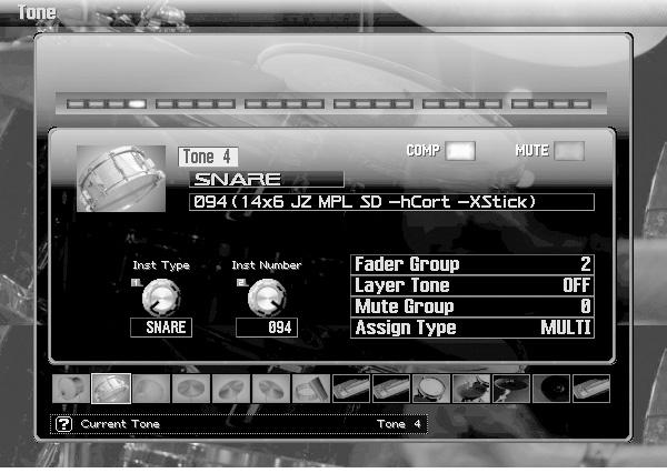
93

94
95
96 Velocity Rate Rate Offset Note On Time (Velocity = Note On)
97 Delay Rate Rate Velocity Curve Offset Time Note On
98

99 Inst Pan Input Level Tone Output Level Level COMP/ Reverb Send Level Output Assign MFX to MFX to Mixer DRY to Reverb

100
OCTAPAD SPD-30 Effects List
 OCTAPAD SPD-30 Effects List The multi-effects feature 30 different kinds of effects. Number Effect Name 00 THRU 01 SUPER FILTER 02 STEP FILTER 03 FILTER+DRIVE 04 AUTO WAH 05 COMPRESSOR 06 LO-FI COMPRESS
NOTES 4; 6) ROLAND CORPORATION
 ROLAND CORPORATION") Owner s Manual Before using this product, carefully read the sections entitled: USING THE UNIT SAFELY and IMPORTANT NOTES (p. 4; p. 6). These sections provide important information concerning the proper
Owner s Manual Before using this product, carefully read the sections entitled: USING THE UNIT SAFELY and IMPORTANT NOTES (p. 4; p. 6). These sections provide important information concerning the proper
The SPD-SX provides four types of master effect. While performing, you can turn the [CONTROL 1] knob or [CONTROL 2] knob to vary the master effect.
![The SPD-SX provides four types of master effect. While performing, you can turn the [CONTROL 1] knob or [CONTROL 2] knob to vary the master effect.](/thumbs/81/84227212.jpg "The SPD-SX provides four types of master effect. While performing, you can turn the [CONTROL 1] knob or [CONTROL 2] knob to vary the master effect.") Effect Guide Master Effect List FILTER The SPD-SX provides four types of master effect. While performing, you can turn the [CONTROL 1] knob or [CONTROL 2] knob to vary the master effect. This applies a
Effect Guide Master Effect List FILTER The SPD-SX provides four types of master effect. While performing, you can turn the [CONTROL 1] knob or [CONTROL 2] knob to vary the master effect. This applies a
JUNO-106. PLUG-OUT Software Synthesizer Owner s Manual 01A. Copyright 2017 ROLAND CORPORATION
 JUNO-106 PLUG-OUT Software Synthesizer Owner s Manual Copyright 2017 ROLAND CORPORATION 01A Introduction When using the JUNO-106 for the first time, you must specify the MIDI Input/Output setting in the
Sales Manual. Table of Contents. 1. What s new? Explaining the Fantom-G in 10 seconds What can it do? Showing the features of the Fantom-G 2
 Sales Manual Table of Contents Page 1. What s new? Explaining the Fantom-G in 10 seconds 2 2. What can it do? Showing the features of the Fantom-G 2 3. Comparison with the Fantom-X 21 4. Comparison with
PRODUCT SUPPORT. (516) USER (8737) Fax: (516) Triton Series Products
 USER (8737) Fax: (516) Triton Series Products") PRODUCT SUPPORT (516) 333 - USER (8737) product_support@korgusa.com Fax: (516) 333-9108 Triton Series Products Basic Guidelines for Setting Controller Assignments The Triton Keyboards and Triton Rack feature
PRODUCT SUPPORT (516) 333 - USER (8737) product_support@korgusa.com Fax: (516) 333-9108 Triton Series Products Basic Guidelines for Setting Controller Assignments The Triton Keyboards and Triton Rack feature
SYSTEM-100 PLUG-OUT Software Synthesizer Owner s Manual
 SYSTEM-100 PLUG-OUT Software Synthesizer Owner s Manual Copyright 2015 ROLAND CORPORATION All rights reserved. No part of this publication may be reproduced in any form without the written permission of
Data List * The illustration shows the TD-17.
 Data List * The illustration shows the TD-17. 2018 Roland Corporation Contents DRUM KIT.................................................. 3 KIT Screen............................................... 3 CLICK......................................................
Model. Owner s Manual
 Model Thank you, and congratulations on your choice of a Hammond XMc-2, Drawbar Controller. In order to get the most out of this instrument for many years to come, please take the time to read this manual
DREAM DSP LIBRARY. All images property of DREAM.
 DREAM DSP LIBRARY One of the pioneers in digital audio, DREAM has been developing DSP code for over 30 years. But the company s roots go back even further to 1977, when their founder was granted his first
ZOOM STUDIO. Safety Precautions. Please observe the following safety tips and precautions to ensure hazard-free use of the 1202.
 Operation Manual Thank you for selecting the ZOOM STUDIO (hereafter called The ). The is a sophisticated effect processor with the following features: A total of 512 preset effect programs (32 effects
Before You Start. Program Configuration. Power On
 StompBox is a program that turns your Pocket PC into a personal practice amp and effects unit, ideal for acoustic guitar players seeking a greater variety of sound. StompBox allows you to chain up to 9
Table of Contents Insert Effect size1
 E 1 Table of Contents Table of Contents Overview... 1 Insert Effects... 1 Effect Size... 2 Effect Input/Output... 2 Grouping... 3 Master Effects... 3 Program... 4 Program - Single/Double OSC mode... 4
Contents. Parameter Guide. Arpeggio Program Parameters Analog Part Digital Part Effects Pattern Sequencer...
 Parameter Guide Contents Program Parameters....................................... 2 Program Edit............................................. 2 Part Edit.................................................
Presents. Dan Tranh. for NI KONTAKT 4+ Go to Index: 2
 Presents Dan Tranh for NI KONTAKT 4+ 1 Index Index 2 About the Dan Tranh 3 The three different Instrument Types 4 General Stuff 5 About the Presets 6 The Instrument Panel 7 The Main Page 7 The Articulation
* Apple, ipad, iphone, ipod touch, and itunes are trademarks of Apple Inc., registered in the U.S. and other countries. * All product names and
 Owner s Manual E 2 * Apple, ipad, iphone, ipod touch, and itunes are trademarks of Apple Inc., registered in the U.S. and other countries. * All product names and company names are the trademarks or registered
PowerCore 01 Manual. Manual for PowerCore 01
 PowerCore 01 Manual English Manual for PowerCore 01 SUPPORT AND CONTACT DETAILS TABLE OF CONTENTS TC SUPPORT INTERACTIVE The TC Support Interactive website www.tcsupport.tc is designed as an online support
Contents. Basic Operation... 3 EFFECT... 5 MENU... 24
 Parameter Guide * Company names and product names appearing in this document are registered trademarks or trademarks of their respective owners. 2018 Roland Corporation 01 Contents Basic Operation...........................................
BLOQ FOR KONTAKT 5 - USER MANUAL 1.0 by Sharooz Raoofi
 BLOQ FOR KONTAKT 5 - USER MANUAL 1.0 by Sharooz Raoofi IMPORTANT: Bloq does not include Kontakt 5. You will need to own or purchase the full software from Native Instruments. http://www.native-instruments.com/en/products/komplete/samplers/kontakt-5/
VB-99 V-Bass System. On-the-Gig Sound Settings. Workshop ÂØÒňΠVB99WS03
 ÂØÒňΠWorkshop VB-99 V-Bass System On-the-Gig Sound Settings 009 Roland Corporation U.S. All rights reserved. No part of this publication may be reproduced in any form without the written permission of
CLA VINET USER GUIDE
 USER GUIDE TABLE OF CONTENTS CHAPTER 1 INTRODUCTION...3 1.1 PRODUCT OVERVIEW... 4 1.2 CONCEPTS AND TERMINOLOGY... 4 1.3 COMPONENTS... 5 1.4 FUNCTIONAL BLOCK/FLOW DIAGRAM... 6 1.5 STARTING CLAVINET... 6
Operation Manual. Basic FX Suite
 Operation Manual Basic FX Suite EN Contents Contents Basic FX Suite...2 Sweet Spot Morphing Channel Strip...2 REV-X...2 Guitar Amp Classics...2 How to Open the VST Plug-ins...3 From the Inspector...3 From
CHAPTER 7 1 SOUND. Effects. Level
 Editing Effects: Chapter 7 CHAPTER 7 EDITING EFFECTS ABOUT SIGNAL PROCESSING TIP: The built-in effects processor of the QS6 is similar to that of the Alesis QuadraVerb 2, capable of generating multiple,
The Atmosphere. Res System Resolution, the sample rate of the digital effects engine. Turn down for slower, lower, longer, grainier, more lofi reverb.
 Decay Reverb decay time. CTRL1 Displayed on the screen under Decay. CTRL2 Displayed on the screen above Tempo. Sidebar Markers tell you what features are active. BYP lights up red for Trails Bypass mode.
2017 VCE VET Music Industry: Sound Production examination report
 2017 VCE VET Music Industry: Sound Production examination report General comments Overall, students performed very well on the 2017 VCE VET Music Industry: Sound Production examination. However, there
ÂØÒňÎ. Workshop. Advanced Fantom-X Recording Techniques. No. 10 in the Fantom-X Workshop Series
 ÂØÒňΠWorkshop Advanced Fantom-X Recording Techniques No. 10 in the Fantom-X Workshop Series 1 2004 Roland Corporation U.S. All rights reserved. No part of this publication may be reproduced in any form
WK-7500 WK-6500 CTK-7000 CTK-6000 BS A
 WK-7500 WK-6500 CTK-7000 CTK-6000 Windows and Windows Vista are registered trademarks of Microsoft Corporation in the United States and other countries. Mac OS is a registered trademark of Apple Inc. in
1. Use a USB cable to connect the Nextone to your computer, and then turn on the power of the Nextone. MEMO
 Using Nextone Editor Nextone Editor is editor software that lets you create your own personalized sounds by using the Nextone s CUSTOM mode to edit detailed settings for the preamp, power amp, and effects.
The included VST Instruments
 The included VST Instruments - 1 - - 2 - Documentation by Ernst Nathorst-Böös, Ludvig Carlson, Anders Nordmark, Roger Wiklander Additional assistance: Cecilia Lilja Quality Control: Cristina Bachmann,
TFX256 PRO. Digital Effect Processor
 TFX PRO Digital Effect Processor SAFTY PRECAUTIONS SAFETY PRECAUTIONS! WARNING - TO REDUCE THE RISK OF FIRE OR ELECTRIC SHOCK, DO NOT EXPOSE THIS UNIT TO RAIN OR MOISTURE. Do not allow water or liquids
TURN2ON BLACKPOLE STATION POLYPHONIC SYNTHESIZER MANUAL. version device by Turn2on Software
 MANUAL version 1.2.1 device by Turn2on Software http://turn2on.ru Introduction Blackpole Station is a new software polyphonic synthesizer for Reason Propellerhead. Based on 68 waveforms in 3 oscillators
Wavelore American Zither Version 2.0 About the Instrument
 Wavelore American Zither Version 2.0 About the Instrument The Wavelore American Zither was sampled across a range of three-and-a-half octaves (A#2-E6, sampled every third semitone) and is programmed with
Owner s Manual AC & BATTERY POWERED FET
 Owner s Manual AC DC AC & BATTERY POWERED FET Thank you, and congratulations on your choice of BOSS AC-3 Acoustic Simulator. Before using this unit, carefully read the sections entitled: USING THE UNIT
I personally hope you enjoy this release and find it to be an inspirational addition to your musical toolkit.
 1 CONTENTS 2 Welcome to COIL...2 2.1 System Requirements...2 3 About COIL...3 3.1 Key Features...3 4 Getting Started...4 4.1 Using Reaktor...4 4.2 Included Files...4 4.3 Opening COIL...4 4.4 Control Help...4
NOVA Owners Manual For Operating System Version 4.1
 NOVA Owners Manual For Operating System Version 4.1 Introducing TABLE OF CONTENTS Front Panel............................................................................... 2 Rear Panel................................................................................
OCS-2 User Documentation
 OCS-2 User Documentation nozoid.com 1/17 Feature This is the audio path wired inside the synthesizer. The VCOs are oscillators that generates tune The MIX allow to combine this 2 sound sources into 1 The
dbtechnologies DEVICE PLUGINS COD _Section_C_REV. 1.0
 VER. 3.0 DEVICE PLUGINS COD. 420120251_Section_C_REV. 1.0 VIO L210 Line Array Module... 3 Compact View... 3 Expanded View... 3 VIO S318 Subwoofer (bassreflex)... 5 Compact View... 5 Expanded View... 5
Square I User Manual
 Square I User Manual Copyright 2001 rgcaudio Software. All rights reserved. VST is a trademark of Steinberg Soft- und Hardware GmbH Manual original location: http://web.archive.org/web/20050210093127/www.rgcaudio.com/manuals/s1/
BoomTschak User s Guide
 BoomTschak User s Guide Audio Damage, Inc. 1 November 2016 The information in this document is subject to change without notice and does not represent a commitment on the part of Audio Damage, Inc. No
PG-8X 2.0. Users Manual
 PG-8X 2.0 Users Manual by MLVST (Martin Lueders) 2016 Introduction The PG- 8X is a virtual synthesizer, inspired by the Roland JX-8P with the PG-800 programmer. The synth architecture is a standard 2-
Suppose you re going to mike a singer, a sax, or a guitar. Which mic should you choose? Where should you place it?
 MICROPHONE TECHNIQUE BASICS FOR MUSICAL INSTRUMENTS by Bruce Bartlett Copyright 2010 Suppose you re going to mike a singer, a sax, or a guitar. Which mic should you choose? Where should you place it? Your
QUICK START. How to Read This Manual. Thank you, and congratulations on your choice of the Roland /
 QUICK START Thank you, and congratulations on your choice of the Roland /. Before using this unit, carefully read the sections entitled: IMPORTANT SAFETY INSTRUCTIONS (Owner s Manual p. 2), USING THE UNIT
Quick Start. Overview Blamsoft, Inc. All rights reserved.
 1.0.1 User Manual 2 Quick Start Viking Synth is an Audio Unit Extension Instrument that works as a plug-in inside host apps. To start using Viking Synth, open up your favorite host that supports Audio
Data List. Copyright 2016 ROLAND CORPORATION
 Data List Copyright 2016 ROLAND CORPORATION Contents DRUM KIT.................................................. 3 DRUM KIT Screen......................................... 3 KIT SETTINGS............................................
Stylish, Light, Compact Design. Authentic Piano Performances. Wide Variety of Tones For Use in Many Musical Genres
 Owner s Manual Thank you, and congratulations on your choice of the Roland Digital Piano FP-3. Main Features Stylish, Light, Compact Design The refined design fits in anywhere; and since it is so lightweight
Kemper Profiler Midi parameters
 Kemper Profiler Midi parameters contents: midi CC list NRPN values values for effect type (related to NRPN data) KEMEPER MIDI CC REFERENCE CHART, V.4.2 CC RANGE FUNCTION CC RANGE FUNCTION kemper midi data:
NOTES 2 3, 4) ROLAND CORPORATION
 ROLAND CORPORATION") Owner s Manual Before using this unit, carefully read the sections entitled USING THE UNIT SAFELY and IMPORTANT NOTES (p. 2 3, p. 4). These sections provide important information concerning the proper
Owner s Manual Before using this unit, carefully read the sections entitled USING THE UNIT SAFELY and IMPORTANT NOTES (p. 2 3, p. 4). These sections provide important information concerning the proper
Understanding and using your. moogerfooger. MF-103 Twelve Stage Phaser. MOOG MUSIC, Inc. Asheville, NC USA
 Understanding and using your moogerfooger MF-103 Twelve Stage Phaser MOOG MUSIC, Inc. Asheville, NC USA Welcome to the world of moogerfooger Analog Effects Modules! Your Model MF-103 Twelve-Stage Phaser
Safety Precautions. Important Safety Instructions
 Thank you for purchasing this digital piano. For optimal operation and security, please read this manual carefully and keep it for future reference. Safety Precautions The lightning flash with arrowhead
ETHERA EVI MANUAL VERSION 1.0
 ETHERA EVI MANUAL VERSION 1.0 INTRODUCTION Thank you for purchasing our Zero-G ETHERA EVI Electro Virtual Instrument. ETHERA EVI has been created to fit the needs of the modern composer and sound designer.
Ample China Pipa User Manual
 Ample China Pipa User Manual Ample Sound Co.,Ltd @ Beijing 1 Contents 1 INSTALLATION & ACTIVATION... 7 1.1 INSTALLATION ON MAC... 7 1.2 INSTALL SAMPLE LIBRARY ON MAC... 9 1.3 INSTALLATION ON WINDOWS...
Nemesis MIDI Implementation
 Nemesis MIDI Implementation Parameter CC# Range Value Description Factory Delay Engine 1 0-23 Selects and loads delay effect engine (with all parameters) 0 Digital 1 Diffuse 2 Analog 3 Tape 4 Noise Tape
Operation Manual. Introduction. Contents
 Operation Manual Introduction Thank you for selecting the ZOOM MODELING GUITAR AMPLIFIER FIRE-15 (simply called the "FIRE-15" in this manual). Please take the time to read this manual carefully so as to
Table of Contents. Introduction Editing Preparations Editing a synth program Quick Start... 7
 Thank you for purchasing the Korg microkorg S synthe sizer/ vocoder. To ensure trouble-free enjoyment, please read this manual carefully and use the product correctly. Introduction... 1 Explains the features
User's Manual. HUSH Licensed by
 P R O G R A M M A B L E 2 4 - B I T D S P G U I T A R P R E A M P User's Manual HUSH Licensed by May be covered by one or more of the following: U.S. Patents #4538297, 4647876, 4696044, 4745309, 4881047,
SNAKEBITE SYNTH. User Manual. Rack Extension for Propellerhead Reason. Version 1.2
 SNAKEBITE SYNTH Rack Extension for Propellerhead Reason User Manual Version 1.2 INTRODUCTION Snakebite is a hybrid digital analog synthesizer with the following features: Triple oscillator with variable
Owner s Manual. Page 1 of 23
 Page 1 of 23 Installation Instructions Table of Contents 1. Getting Started! Installation via Connect! Activation with Native Instruments Service Center 2. Pulse Engines Page! Pulse Engine Layers! Pulse
Contents. Basic Operation... 3 MENU Effect Saving a Sound (WRITE)... 47
... 47") Parameter Guide 01 Contents Basic Operation........................................... 3 Basic Procedure for Effect Editing........................ 3 Effect Placement..................................
Parameter Guide 01 Contents Basic Operation........................................... 3 Basic Procedure for Effect Editing........................ 3 Effect Placement..................................
Thank you, and congratulations on your choice of the Roland GR-33 Guitar Synthesizer.
 Owner s Manual Thank you, and congratulations on your choice of the Roland GR-33 Guitar Synthesizer. Before using this unit, carefully read the sections entitled: USING THE UNIT SAFELY (page 2 3) IMPORTANT
USER MANUAL VIVALDI MZ550A. Distribution Mixer Amplifier
 USER MANUAL VIVALDI MZ550A Distribution Mixer Amplifier 1. Security Precautions Carefully READ the instruction in this manual before use. Be sure to OBSERVE the INSTRUCTION in this manual regard convention
Written by Jered Flickinger Copyright 2017 Future Retro
 Written by Jered Flickinger Copyright 2017 Future Retro www.future-retro.com TABLE OF CONTENTS Page 1 - Overview Page 2 Inputs and Outputs Page 3 Controls Page 4 Modulation Sources Page 5 Parameters Instrument
Contents. Safety Precautions 2 Usage Precautions 2. Getting Familiar With Some Basic Terms 3
 Contents Safety Precautions 2 Usage Precautions 2 Getting Familiar With Some Basic Terms 3 Names and Functions of Controls and Connectors 4 Front Panel 4 Rear Panel 5 Connection Examples 6 Connection to
TiaR c-x-f synth rev 09. complex X filter synthesizer. A brief user guide
 1 Introduction TiaR c-x-f synth rev 09 complex X filter synthesizer A brief user guide by Thierry Rochebois The cxf synthesizer is a jsfx software synthesizer designed for Reaper. It can be downloaded
Spider IV 15. Pilot s Handbook Manuel de pilotage Pilotenhandbuch Pilotenhandboek Manual del Piloto 取扱説明書
 Spider IV 15 Pilot s Handbook Manuel de pilotage Pilotenhandbuch Pilotenhandboek Manual del Piloto 取扱説明書 Get free lessons and tones! Join Spider Online! www.line6.com/spideronline 40-00-0187 Pilot s Handbook
MIXER POWER AMPLIFIER BG-130
 OPERATING INSTRUCTIONS MIXER POWER AMPLIFIER BG-115 BG-130 TO REDUCE THE RISK OF ELECTRICAL SHOCK, DO NOT REMOVE COVER. NO USER SERVICEABLE PARTS INSIDE. REFER SERVICING TO QUALIFIED SERVICE PERSONNEL
ÂØÒňΠGuitar synthesizer July 10, 1995
 GR-1 ÂØÒňΠGuitar synthesizer July 10, 1995 Supplemental Notes MIDI Sequencing with the GR-1 This is an application guide for use with the GR-1 and an external MIDI sequencer. This guide will cover MIDI
PM800 powermixer. user manual
 PM800 powermixer user manual Musikhaus Thomann e. K. Treppendorf 30 96138 Burgebrach Germany Telephone: +49 (9546)-9223-0 email: info@thomann.de Internet: www.thomann.de 17.11.2011 Table of contents Table
JV-1080 Software Synthesizer Owner s Manual
 JV-1080 Software Synthesizer Owner s Manual Copyright 2017 ROLAND CORPORATION 01 Introduction For details on the settings for the DAW software that you re using, refer to the DAW s help or manuals. About
APPENDIX. MIDI Controller List. MIDI Controller List
 Some controllers adhere to the normal midi-specified use (eg modwheel, volume) but most are used arbitrarily (and therefore may clash with parameter assignments of other products). We have tried to avoid
ZOOM PLAYER. Operation Manual ADVANCED GUITAR EFFECTS PROCESSOR. Outstanding Features
 ADVANCED GUITAR EFFECTS PROCESSOR Thank you for selecting the Advanced Guitar Effects Processor ZOOM Player 1010 (hereafter called "1010"). Outstanding Features ZOOM PLAYER Operation Manual 25 versatile
Important Safety Information
 Owner's Manual Important Safety Information FCC Notice This equipment has been tested and found to comply with the limits for a Class B digital device, pursuant to Part 15 of the FCC Rules. These limits
INSTRUCTION MANUAL POWERED MIXER MX-628
 INSTRUCTION MANUAL POWERED MIXER MX-628 Please follow the instructions in this manual to obtain the optimum results from this unit. We also recommend that you keep this manual handy for future reference.
LIVE 16 ORDERCODE D2211
 LIVE 16 ORDERCODE D2211 Congratulations! You have bought a great, innovative product from DAP Audio. The DAP Audio LIVE 16 brings excitement to any venue. Whether you want simple plug-&-play action or
MIDX Boss GT-1 - MIDI Implementation
 MIDX Boss GT-1 - MIDI Implementation Version: May 03 2018 V2.9 PC# 00 - PC# 98 - Change Patch Number (U01-U99) PRESET CC s RECALL/SELECT PATCH = CC# 4 (0-98) STORE TO PATCH = CC# 5 (0-98) STORE TO CURRENT
Mono/Fury. VST Software Synthesizer. Version by Björn Full Bucket Music
 Mono/Fury VST Software Synthesizer Version 1.0 2010-2012 by Björn Arlt @ Full Bucket Music http://www.fullbucket.de/music VST is a trademark of Steinberg Media Technologies GmbH Mono/Poly is a registered
Spider. Pilot s Handbook Manuel de pilotage Pilotenhandbuch Pilotenhandboek Manual del Piloto 取扱説明書
 Spider IV Pilot s Handbook Manuel de pilotage Pilotenhandbuch Pilotenhandboek Manual del Piloto 取扱説明書 Get free lessons and tones! Join Spider Online! www.line6.com/spideronline 40-00-0186 Pilot s Handbook
Combined Effects Pedal
 Combined Effects Pedal CONTENTS Precautions Introdution Main Features Pedal Layout Operation Modes Live Mode Preset Mode Effect Modules Tap Tempo Using The FX LOOP Connections Technical Parameters 01
Table of contents. Saving and Loading Data...65 Saving to internal memory...65 Loading from internal memory...65 Import...65
 E 1 Table of contents Introduction... 3 Main Features... 3 Quick Start... 4 Getting ready to play...4 Selecting and playing sounds...4 Selecting a program... 4 Using the full-size keyboard or a Kaoss Pad
FG Connects Live Customer Interaction Manual
 Fantom-G Ver.50 For sales reps FG Connects Live Customer Interaction Manual Impress your customers with FG Connects Live, showcasing the Fantom-G's new tones, Favorites function, and ARX-series expansion
Operation is effortless. Just twist the knobs and press the pedals to obtain cutting-edge V-Guitar sounds.
 Owner s Manual * With the factory settings, this device will enter Sleep mode (power conservation mode) when ten hours have elapsed since the last operation, or since the last audio input while in Stop
CABINET POWERED MIXING CONSOLE
 R SHS AUDIO SPMU- 00 CABINET POWERED MIXING CONSOLE USER'S MANUAL SAFETY INSTRUCTIONS SPECIFICATIONS Inputs Input modes Input Impedance Rated Input level Connector WARNING - TO REDUCE THE RISK OF FIRE
VK-1 Viking Synthesizer
 VK-1 Viking Synthesizer 1.0.2 User Manual 2 Overview VK-1 is an emulation of a famous monophonic analog synthesizer. It has three continuously variable wave oscillators, two ladder filters with a Dual
Performance Editor Essential Owner s Manual
 Performance Editor Essential Owner s Manual Copying of the commercially available music sequence data and/or digital audio files is strictly prohibited except for your personal use. The software and this
Table of Contents. Owner s Manual. 1. Overview & Getting Started. 2. Engines. 3. FX Modules. 4. Rhythms. 5. Flux. 6. X-Y Pad & Macros. 7.
 Table of Contents 1. Overview & Getting Started 2. Engines 3. FX Modules 4. Rhythms 5. Flux 6. X-Y Pad & Macros 7. Presets 8. Additional Info Overview MOVEMENT is an efects processor designed to add rhythmic,
64i 1.28i 2.56i DIGITAL DELAYS OWNER S MANUAL
 64i 1.28i 2.56i DIGITAL DELAYS OWNER S MANUAL Originally written by ADA SIGNAL PROCESSORS, INC. Scanned and edited by Jur at 1 th of may 2004. Original ADA logo edited and rendered by Barend Onneweer of
QUICK START. How to Read This Manual. Thank you, and congratulations on your choice of the Roland
 QUICK START Thank you, and congratulations on your choice of the Roland (FA-76). Before using this unit, carefully read the sections entitled: IMPORTANT SAFETY INSTRUCTIONS (Owner s Manual p. 2), USING
CONTENTS / INTRODUCTION
 CONTENTS / INTRODUCTION CONTENTS FRONT PANEL... 2 REAR PANEL... 3 SETTING UP... 4 APPLICATIONS-BASIC... 4 APPLICATIONS-ADVANCED... 5 ABOUT ANALOGUE SYNTHESIS... 6 NOVATIONISH... 14 SOUNDS-PROGRAMS & PERFORMANCES...
Combined Effects Pedal
 Combined Effects Pedal Precautions Power Supply Use the correct AC outlet to connect the power adapter. Use a power transformer with a negative external voltage of 9V (± 10%) 300mA, otherwise it will cause
INTRODUCTION WARNING! IMPORTANT SAFETY INSTRUCTIONS. Congratulations on your purchase of this MG Gold amplifier from Marshall Amplification.
 OWNER S MANUAL INTRODUCTION WARNING! IMPORTANT SAFETY INSTRUCTIONS Congratulations on your purchase of this MG Gold amplifier from Marshall Amplification. The MG provides modern Marshall tones for the
1 - Mode Section This section contains the Performance, Program, Finder / Demo, Compare, Global, and Write buttons.
 CONTENTS FRONT PANEL... 2 REAR PANEL... 3 SETTING UP... 4 APPLICATIONS-ADVANCED... 5 APPLICATIONS-BASIC... 4 ABOUT ANALOGUE SYNTHESIS... 6 NOVATIONISH... 1 4 SOUNDS-PROGRAMS & PERFORMANCES... 1 5 SELECTING
XT-1. One Pedal, Infinite Guitars User Manual (EN)
") XT-1 One Pedal, Infinite Guitars User Manual (EN) "Sim1 - Sound Imprinting' is a registered trademark property of Sim1 Srl. All other product names and images, trademarks and artists names are the property
XT-1 One Pedal, Infinite Guitars User Manual (EN) "Sim1 - Sound Imprinting' is a registered trademark property of Sim1 Srl. All other product names and images, trademarks and artists names are the property
Photone Sound Design Tutorial
 Photone Sound Design Tutorial An Introduction At first glance, Photone s control elements appear dauntingly complex but this impression is deceiving: Anyone who has listened to all the instrument s presets
PM800 powermixer. user manual
 PM800 powermixer user manual Musikhaus Thomann Thomann GmbH Hans-Thomann-Straße 1 96138 Burgebrach Germany Telephone: +49 (0) 9546 9223-0 E-mail: info@thomann.de Internet: www.thomann.de 16.02.2016, ID:
PX-5S. USER S GUIDE (Tutorial)
") EN PX-5S USER S GUIDE (Tutorial) Before using this Digital Piano for the first time, be sure to read the separate USER S GUIDE (Basics) to familiarize yourself with basic operations. PX5S-E-2C Contents
EN PX-5S USER S GUIDE (Tutorial) Before using this Digital Piano for the first time, be sure to read the separate USER S GUIDE (Basics) to familiarize yourself with basic operations. PX5S-E-2C Contents
IEM 200 R UHF receiver. user manual
 IEM 200 R UHF receiver user manual Musikhaus Thomann Thomann GmbH Hans-Thomann-Straße 1 96138 Burgebrach Germany Telephone: +49 (0) 9546 9223-0 E-mail: info@thomann.de Internet: www.thomann.de 17.11.2015,
- for CreamWare SCOPE -
 bx_digital MANUAL - for CreamWare SCOPE - 2006 by BRAINWORX GmbH Brainworx Music & Media GmbH Hitdorfer Str. 10 40764 Langenfeld info@brainworx-music.de 1 INDEX 1. What is the bx_digital? 3 2. What is
PULSAR DUAL LFO OPERATION MANUAL
 PULSAR DUAL LFO OPERATION MANUAL The information in this document is subject to change without notice and does not represent a commitment on the part of Propellerhead Software AB. The software described
Parameter Guide. Copyright 2017 ROLAND CORPORATION
 Parameter Guide Copyright 2017 ROLAND CORPORATION 01 Contents 2 Detailed Settings for a Program (Program Edit).............. 4 Detailed Settings for Each Zone (Zone Edit)................. 4 Changing the
AN Expert Editor. Manual. Important Notices
 AN Expert Editor Manual Important Notices The AN Expert Editor provides an easy, intuitive way to edit and create your own original AN voices for the PLG150-AN Plug-in Board. Do not use any of the panel
EasyStart CONTENTS. Connections; Tuning; Selecting Programs 2. Saving Programs; Individual Mode; Expression Quick Assign; 3
 EasyStart Main Features Korg s REMS modeling technology delivers 72 realistic classic and modern amp, cabinet and effects models 16 types of drive & amp models cover everything from vintage overdrive to