27 November 01 RST-504 DOCUMENT SUMMARY Chassis Schematic (with intercom) Aircraft Electrical Installation
|
|
|
- Reynard Bradford
- 5 years ago
- Views:
Transcription
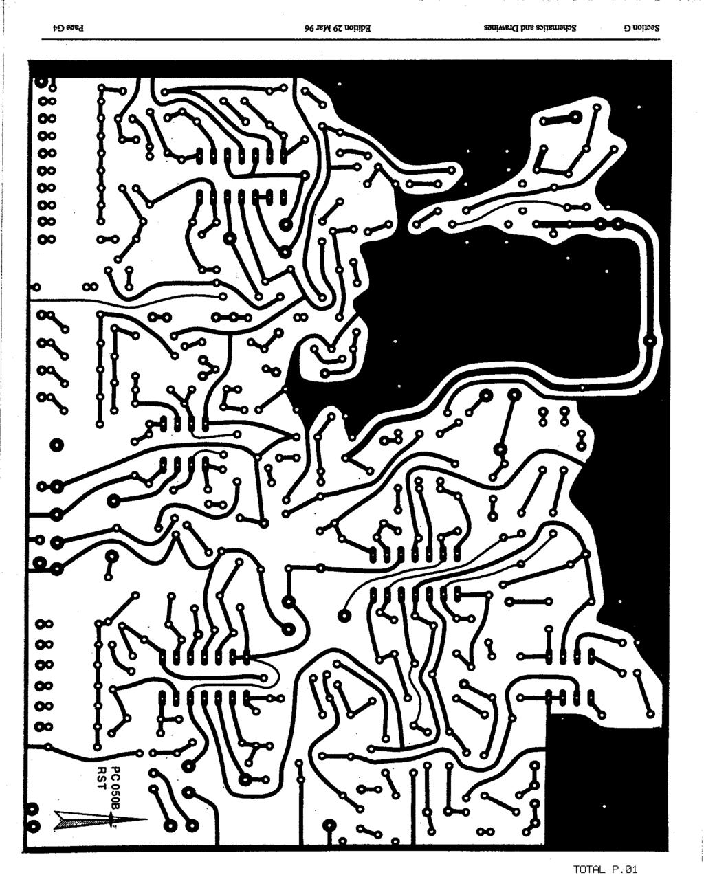
1 RST ENGINEERING MAIL: Grass Valley Ave SHIP: Downwind Court Grass Valley CA Voice (916) Web Page: 27 November 01 RST-504 DOCUMENT SUMMARY Chassis Schematic (with intercom) Aircraft Electrical Installation Theory of Operation PCB Parts Values PCB Reference Designators PCB Traces PCB X-Ray View (poor quality) Chassis Parts View Chassis Schematic (without intercom) PCB Schematic (without intercom) PCB Schematic (with intercom) Aircraft Mechanical Installation
2
3
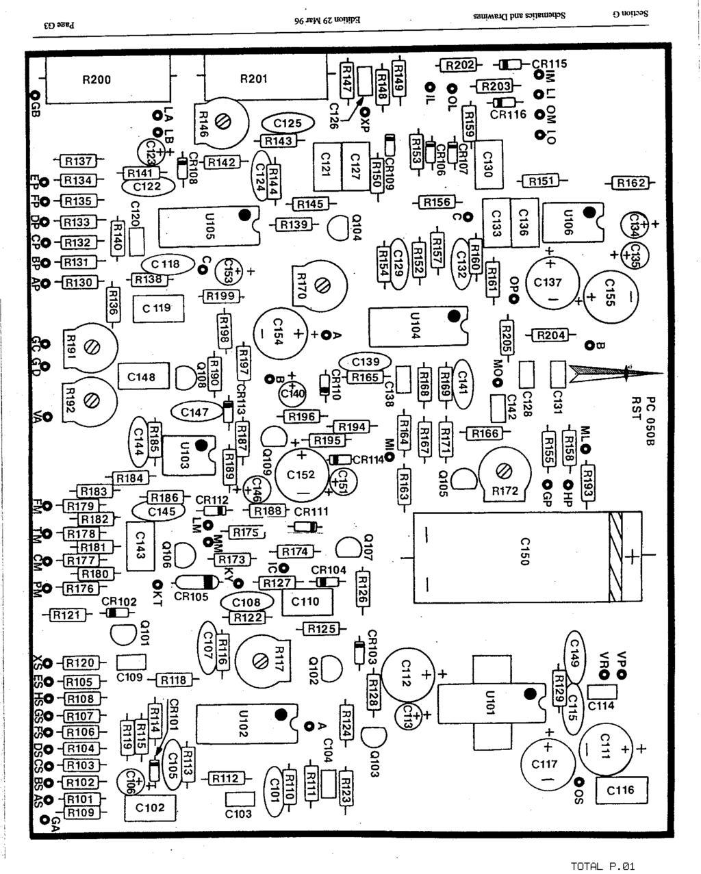
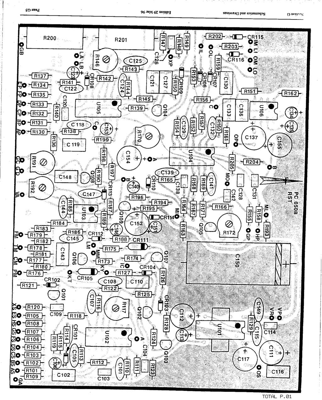
4 D. THEORY OF OPERATION [Information pertaining to audio panels equipped with the RST-506 Intercom package is shown in brackets]. The basic function of the RST-504 is to condition and mix the various audio signals in the aircraft and amplify them for detection in the aircraft speaker and headphones. Also included in the circuitry are a marker beacon audio attenuation circuit [a voice-activated (VOX) intercommunication system], and automatic routing of microphone audio and key signals. In normal operation, one or more of the eight possible inputs will be amplified and routed to either speaker or headphones, selected by switches S2 through S9. The RST-504 also has a NORMAL / BYPASS switch, S1, which acts as a fail-safe should the panel ever malfunction. In the bypass position, the COM 1 speaker and phones outputs are hardwired to the speaker and phones, providing COM 1 radio operation. The audio panel operation will be explained in six sections -- General, Speaker Amplifier, Phones Amplifier, Intercom, Marker Attenuation Circuit, and Power Supply. Refer to the chassis Schematic (Drawing # ) and PC050 schematic (Drawing # ) for clarification during circuit descriptions. 1. General a. Low level (headphone) audio from COM 1, COM 2, ADF, AUX, DME, NAV 1, and NAV 2 enters the audio panel at J1 and J3 and is routed to switches S3 through S9 where it is loaded to ground with a 560 ohm resistor. These switches determine whether the audio is terminated (off), or routed to the speaker or phones amplifier. The MKR BCN audio goes through conditioning circuitry before it is switched to the speaker of phones amplifier. b. The AUTO switch routes the COM audio from the radio selected by the transmit switch (XMIT 1/XMIT 2) to either the speaker or phones amplifier as selected. For example, with the AUTO switch in the speaker position and XMIT 1 selected, COM 1 audio would be present in the speaker. If the XMIT switch is flipped to the XMIT 2 position, COM 2 s audio is provided to the speaker (regardless of the position of either COM 1 or COM 2 switches). The xmit switch, S11 switches the key and audio lines for COM 1 and COM 2 and the COM 1 and COM 2 audio for the AUTO switch. c. COM 1 and COM 2 speaker audio signals are terminated to ground through the 10 ohm resistors (R100 and R201). 2. Speaker Amplifier (see Drawing # ) Section D Theory of Operation Edition 27 Mar 96 Page D1
5 a. Selected low level audio from S2 through S9 enters PC050 at points AS through HS and is summed together at R109 (with the exception of AUX audio from S6, which is introduced later). Operational amplifier U102D attenuates this signal 3 db with the output appearing at U Under normal operation, this attenuated audio is applied to the main amplifier input (U101-8) through R111 and C104. R123 sets the input impedance of U101. b. A portion of the audio from U is fed through C103 and R112 to the AUX input muting circuit. The audio is amplified by U102C (10X) and rectified to a dc level by CR101 and C106. This dc level is applied to comparator U102B at the inverting input, pin 6. R117 sets the dc level at the non-inverting input, U The voltage at C106 is around 0 volts and there is little or no audio at U This potential rises as the audio level increases. When the level at U102-5 exceeds that at U102-6, the output at U102-7 rises to around 10 volts. This provides the bias voltage required to turn on Q101. Audio from the AUX input (XS) is amplified by Q101 and applied to the amplifier (at U101-8) through C110. When the level at U102-6 exceeds that at U102-5, U102 s output drops to around 0 volts turning off Q101 and preventing any AUX audio from being passed to the main amplifier (U101). c. The speaker must be muted during both transmit [and ICS functions] to prevent feedback. Q102 and Q103 provide this muting. IN transmit, point KY is pulled low by the key line. This provides the bias required to turn on Q102, bringing its collector voltage up to about 10 volts. This, in turn, provides the bias voltage required to turn on Q103 and shunt any audio present at U101-8 (the main amplifier input) to ground, thus muting all speaker audio. [In the ICS position, 10 volts is applied to point IC which turns on Q107, thus bringing its collector voltage to ground and muting the speaker as described above.] The main speaker amplifier, U101, is a TBA 810 power integrated circuit. Its gain is set at approximately 60 with R128 and C112. The output at U passes through dc blocking capacitor C117 to OS, the speaker output. 3. Phones Amplifier a. The phones amplifier circuitry is very similar to that of the speaker amplifier. Low level audio is input at points AP through FP and [R191 with panels equipped with intercom option]. The audio is attenuated by U105C and applied to the phones amplifier at U The AUX muting circuit involving U105B, U105A and Q104 is similar to that described in the speaker amplifier section, above. b. The COM 1 and COM 2 inputs are conditioned so that when one COM is transmitting, the other one is muted (i.e. COM 2 is muted when transmitting on COM 1). This prevents possible bleedover between radios. COM 1 audio is input at point HP and applied to U104-2 through R158 and C131. As long as point OL (COM 2 key line) is at around 12 volts (unkeyed state), audio will be amplified by U104A (unity gain) and summed with the rest of the phones inputs at U If OL is near 0 volts (COM 2 keyed), then biasing is removed from U104-3 and little or no audio will be present at Section D Theory of Operation Edition 27 Mar 96 Page D2
6 U The above description also applies to the COM 2 circuit incorporating GP, IL, and U104B. c. The main phones amplifier is a LM386 low voltage audio power amplifier. The gain is set at approximately 60 by R162 and C134. The output at pin 5 is set internally at V+/2 (5 volts for a 10 volt supply) to provide maximum output swing. After passing through dc blocking capacitor C137, headphone audio is output at point OP. 4. [Intercommunications System] a. [Built into the RST-504 audio panel is an optional voice-activated intercom system. The system is activated when S12 is rotated to the ICS ON position by providing a 10 volt dc signal to point IC which activates the ICS circuitry. The 10 volt signal at point IC turns on Q106 and Q107. The collector of Q107 is pulled to ground muting the speaker amplifier through R126 and turns on the MM marker lamp through CR111 and R175) one-half brilliance to indicate that the ICS is activated. b. The emitter voltage of Q106 rises to approximately 9.3 volts to bias ON the four microphones through R176 (PM), R177 (CM), R178 (TM), and R179 (FM). These four microphones signals are then summed at C143 and amplified (3X) by U103B. Audio from U103-7 passes through R187 and C148 to ICS volume control R191. A percentage (0-100%) of this audio is selected from the wiper of R191 for presentation to the phones amplifier, U106, via the summing amp U105C. c. To provide voice activation, a squelch circuit is needed. A portion of the audio from U103-7 is rectified by CR112 and C146 to a dc level, and applied to comparator U103A, pin 2. When the level set by R192 (ICS SQUELCH) is greater than that at pin 2, the output of the comparator goes to near 10 volts and turns on Q108 through CR113 and R190. This shunts any audio present at C148 to ground. When there is sufficient audio to break the squelch, Q108 is turned off and audio is routed to the headphone summing amplifier, U105C.] 5. Marker Attenuation Circuit a. Once a preset marker audio level has been achieved, the marker attenuation circuit will attenuate the marker audio to a comfortable listening level. After the aircraft has passed over the marker beacon, the circuit resets itself to maximum sensitivity. b. Marker beacon audio is fed into point MI on PC050 and loaded to ground with R163. The signal is amplified (2X) by U104C and output at pin 8. In normal, low level operation, this audio will be present at the marker beacon audio output (MO) and applied to S2 (MKR BCN) for selection to the speaker or phones amplifier. Section D Theory of Operation Edition 27 Mar 96 Page D3
7 c. To activate the attenuation circuit, a portion of the audio from U104-8 is rectified by CR110 and C140 to a dc level and applied to comparator input U R170 (MKR TRIG ADJUST) sets the level at U As the audio level at U104-8 increases and the level at U exceeds that at U104-13, the output of U104-D rises to about 10 volts and turns on Q105, bringing its collector voltage to ground. A portion of the audio passing through R166 is then shunted to ground through R172. The degree of attenuation is adjustable from about 3 db to over 60 db by R Power Supply a. Power for the RST-504 comes in to PC050 at point VP. The volt input is filtered by C149 and C150. The positive supply for the marker/indicator lamps is fused with R193 (a 10 ohm, 1/4 watt resistor) and output at point ML. b. CR114, C151, and R194 provide the stable 10 volt reference for Q109, the series pass element. The fairly high current 9.3 volt supply is filtered by C152. To obtain the V+/2 supply, R197 and R198 form a voltage divider to produce the V+/2 signal at U U105D is hooked up in a follower configuration to provide the required current drive for the V+/2 (5 volt) supply. Section D Theory of Operation Edition 27 Mar 96 Page D4
8
9
10
11
12
13
14
15
16
MAINTENANCE MANUAL AUDIO MATRIX BOARD P29/
 MAINTENANCE MANUAL AUDIO MATRIX BOARD P29/5000056000 TABLE OF CONTENTS Page DESCRIPTION................................................ Front Cover CIRCUIT ANALYSIS.............................................
LBI-30705L INSTRUCTIONS FOR AUDIO BOARDS 19A129924G1-G3 DESCRIPTION CIRCUIT ANALYSIS ERICSSONZM ERICSSONZM TABLE OF CONTENTS. Audio Board 19A129924G1
 ERICSSONZM INSTRUCTIONS FOR AUDIO BOARDS 19A129924G1-G3 L TABLE OF CONTENTS Page DESCRIPTION............................................... Front Cover CIRCUIT ANALYSIS............................................
KMA 24 and KMA 24H Bendix/King Audio Control Systems
 KMA 24 and KMA 24H Bendix/King Audio Systems Compact TSO d consoles make audio control push button simple Push button simplicity puts complete, flexible audio control right at your fingertips with Bendix/King
LBI-31807D. Mobile Communications MASTR II REPEATER CONTROL PANEL 19B234871P1. Maintenance Manual. Printed in U.S.A.
 D Mobile Communications MASTR II REPEATER CONTROL PANEL 19B234871P1 Maintenance Manual Printed in U.S.A. This page intentionally left blank 13 PARTS LIST 12 PARTS LIST LBI-31807 11 PARTS LIST 10 SCHEMATIC
9800 Martel Road Lenoir City, TN PMA6000B
 9800 Martel Road Lenoir City, TN 37772 www.ps-engineering.com PMA6000B Audio Control Panel Marker Beacon and Intercom Pilot s Guide and Operation Manual FAA-TSO C50c, C35d EASA ETSO C50c, 2C35d US Patent
MASTR II AUXILIARY RECEIVER 19D417546G7 & G8 & ANTENNA MATCHING UNITS 19C321150G1-G2. Maintenance Manual LBI-30766L. Mobile Communications
 L Mobile Communications MASTR II AUXILIARY RECEIVER 19D417546G7 & G8 & ANTENNA MATCHING UNITS 19C321150G1-G2 Printed in U.S.A Maintenance Manual TABLE OF CONTENTS Page SPECIFICATIONS.....................................................
MAINTENANCE MANUAL AUDIO AMPLIFIER BOARD 19D904025G1 (MDR) AUDIO AMPLIFIER BOARD 19D904025G2 (MDX)
 AUDIO AMPLIFIER BOARD 19D904025G2 (MDX)") A MAINTENANCE MANUAL AUDIO AMPLIFIER BOARD 19D904025G1 (MDR) AUDIO AMPLIFIER BOARD 19D904025G2 (MDX) TABLE OF CONTENTS DESCRIPTION............................................... Page Front Cover CIRCUIT
A MAINTENANCE MANUAL AUDIO AMPLIFIER BOARD 19D904025G1 (MDR) AUDIO AMPLIFIER BOARD 19D904025G2 (MDX) TABLE OF CONTENTS DESCRIPTION............................................... Page Front Cover CIRCUIT
HEATHKIT ELECTRONIC KEYER HD-10
 HEATHKIT ELECTRONIC KEYER HD-10 CIRCUIT DESCRIPTION SCHEMATIC DIAGRAM The letter-number designations on the Schematic Diagram are used to identify resistors, capacitors and diodes. Each designation is
JA Audio Controller
 JA95-001 Audio Controller Rev. A Page 1 Copyright 2013 Jupiter Avionics Corp. All rights reserved Jupiter Avionics Corporation (JAC) permits a single copy of this manual to be printed or downloaded for
JA Audio Controller Six Transceiver
 JA95-002 Audio Controller Six Transceiver Rev. A Page 1 JA95-002 Audio Controller Six Transceiver Copyright 2014 Jupiter Avionics Corp. All rights reserved Jupiter Avionics Corporation (JAC) permits a
PA FAN PLATE ASSEMBLY 188D6127G1 SYMBOL PART NO. DESCRIPTION. 4 SBS /10 Spring nut. 5 19A702339P510 Screw, thread forming, flat head.
 MAINTENANCE MANUAL 851-870 MHz, 110 WATT POWER AMPLIFIER 19D902797G5 TABLE OF CONTENTS Page DESCRIPTION.............................................. Front Page SPECIFICATIONS.................................................
Maintenance Manual LBI-38531G MHz, 110 WATT POWER AMPLIFIER 19D902797G1 DESCRIPTION TABLE OF CONTENTS
 Maintenance Manual LBI-38531G 136-174 MHz, 110 WATT POWER AMPLIFIER 19D902797G1 TABLE OF CONTENTS Page DESCRIPTION.............................................. Front Cover SPECIFICATIONS.................................................
ericssonz LBI-38640E MAINTENANCE MANUAL FOR VHF TRANSMITTER SYNTHESIZER MODULE 19D902780G1 DESCRIPTION
 MAINTENANCE MANUAL FOR VHF TRANSMITTER SYNTHESIZER MODULE 19D902780G1 TABLE OF CONTENTS Page DESCRIPTION........................................... Front Cover GENERAL SPECIFICATIONS...................................
Garmin GMA 340 Audio System
 Cirrus Design Section 9 Pilot s Operating Handbook and FAA Approved Airplane Flight Manual Supplement for Garmin GMA 340 Audio System Includes Optional XM Radio System When the Garmin GMA 340 Audio Panel
TECHNICAL MANUAL ULTRASONIC TEST SET MODEL 42A12D JUNE 15, 1998 REV 00 SEACOM DIVISION
 TECHNICAL MANUAL ULTRASONIC TEST SET MODEL AD JUNE, 998 REV 00 SEACOM DIVISION DUKANE CORPORATION ST. CHARLES, ILLINOIS 607 PHONE: 60/8-00 FAX: 60/8- DOCUMENT NO. 0-TM-008 998 DUKANE CORPORATION 99806-08SC
Apollo Model SL10 Series Audio Selector Panel User s Guide
 Apollo Model SL10 Series Audio Selector Panel December 2001 560-0973-00a No part of this document may be reproduced in any form or by any means without the express written consent of UPS Aviation Technologies,
LBI-30398N. MAINTENANCE MANUAL MHz PHASE LOCK LOOP EXCITER 19D423249G1 & G2 DESCRIPTION TABLE OF CONTENTS. Page. DESCRIPTION...
 MAINTENANCE MANUAL 138-174 MHz PHASE LOCK LOOP EXCITER 19D423249G1 & G2 LBI-30398N TABLE OF CONTENTS DESCRIPTION...Front Cover CIRCUIT ANALYSIS... 1 MODIFICATION INSTRUCTIONS... 4 PARTS LIST AND PRODUCTION
Sensor Interfacing and Operational Amplifiers Lab 3
 Name Lab Day Lab Time Sensor Interfacing and Operational Amplifiers Lab 3 Introduction: In this lab you will design and build a circuit that will convert the temperature indicated by a thermistor s resistance
ERICSSONZ LBI-30398P. MAINTENANCE MANUAL MHz PHASE LOCKED LOOP EXCITER 19D423249G1 & G2 DESCRIPTION TABLE OF CONTENTS
 MAINTENANCE MANUAL 138-174 MHz PHASE LOCKED LOOP EXCITER 19D423249G1 & G2 TABLE OF CONTENTS Page DESCRIPTION... Front Cover CIRCUIT ANALYSIS...1 MODIFICATION INSTRUCTIONS...4 PARTS LIST...5 PRODUCTION
Op Amp Booster Designs
 Op Amp Booster Designs Although modern integrated circuit operational amplifiers ease linear circuit design, IC processing limits amplifier output power. Many applications, however, require substantially
Lecture #2 Operational Amplifiers
 Spring 2015 Benha University Faculty of Engineering at Shoubra ECE-322 Electronic Circuits (B) Lecture #2 Operational Amplifiers Instructor: Dr. Ahmad El-Banna Agenda Introduction Op-Amps Input Modes and
MAINTENANCE MANUAL TRANSMITTER/RECEIVER BOARD CMN-234A/B FOR MLSU141 & MLSU241 UHF MOBILE RADIO TABLE OF CONTENTS
 MAINTENANCE MANUAL TRANSMITTER/RECEIVER BOARD CMN-234A/B FOR MLSU141 & MLSU241 UHF MOBILE RADIO TABLE OF CONTENTS DESCRIPTION... 2 CIRCUIT ANALYSIS... 2 TRANSMITTER... 2 9-Voft Regulator... 2 Exciter...
MAINTENANCE MANUAL EUROPEAN LEASE LINE INTERFACE BOARDS 19D904245G1 AND 19D904744G1
 MAINTENANCE MANUAL EUROPEAN LEASE LINE INTERFACE BOARDS 19D904245G1 AND 19D904744G1 TABLE OF CONTENTS Page SPECIFICATIONS............................................. Front Cover DESCRIPTION...............................................
MAINTENANCE MANUAL AUDIO BOARDS 19D902188G1, G2 & G3
 B MAINTENANCE MANUAL AUDIO BOARDS 19D902188G1, G2 & G3 TABLE OF CONTENTS Page Front Cover DESCRIPTION............................................... CIRCUIT ANALYSIS............................................
JA Audio Controller Data Sheet
 TM JA95-001 Audio Controller Data Sheet Description The JA95-001 audio controller is a compact, lightweight unit that incorporates the latest technology, and is compatible with the current industry standard
AMS44 and AMS44T Dual Channel Audio Controllers OPERATOR S MANUAL
 AMS44 and AMS44T Dual Channel Audio Controllers OPERATOR S MANUAL REV 1.11 December 4, 2002 Northern Airborne Technology Ltd. 1925 Kirschner Road Kelowna, BC, Canada. V1Y 4N7 Telephone (250) 763-2232 Facsimile
EDACS WALL MOUNT STATION. Maintenance Manual. Mobile Communications LBI-31838A TABLE OF CONTENTS
 A Mobile Communications EDACS WALL MOUNT STATION TABLE OF CONTENTS SYSTEM BOARD & REGULATOR BOARD.......... LBI-31892 KEY/DISPLAY BOARD MAINTENANCE MANUAL.... LBI-31940 Maintenance Manual Printed in U.S.A.
Audio Specialties Group Products Division MAS-101 UHF Receive Antenna Combiner Operators Guide
 Audio Specialties Group Products Division MAS-101 UHF Receive Antenna Combiner Operators Guide REV-4 TABLE OF CONTENTS SECTION 1:... 3 1.0 Introduction... 3 SECTION 2:... 3 Features... 3 2.1 Standard Configurations...
2007 MFJ ENTERPRISES, INC.
 Model MFJ-618 INSTRUCTION MANUAL CAUTION: Read All Instructions Before Operating Equipment MFJ ENTERPRISES, INC. 300 Industrial Park Road Starkville, MS 39759 USA Tel: 662-323-5869 Fax: 662-323-6551 VERSION
SPECIFICATIONS: Subcarrier Frequency 5.5MHz adjustable, FM Modulated +/- 50KHz. 2nd 11MHz >40dB down from 5.5MHz
 Mini-kits AUDIO / SUBCARRIER KIT EME75 Version4 SPECIFICATIONS: Subcarrier Frequency 5.5MHz adjustable, FM Modulated +/- 50KHz Subcarrier Output 1.5v p-p Output @ 5.5MHz DESCRIPTION & FEATURES: The Notes
FM Audio/Squelch Board by Steve Dold, W6KCS w6kcs (at) stevedold (dot) com
 stevedold (dot) com") FM Audio/Squelch Board by Steve Dold, W6KCS w6kcs at stevedold dot com Board hardware version 7-8 Firmware version 7.x This board connects to an FM receiver's discriminator/detector and provides squelched,
FM Audio/Squelch Board by Steve Dold, W6KCS w6kcs at stevedold dot com Board hardware version 7-8 Firmware version 7.x This board connects to an FM receiver's discriminator/detector and provides squelched,
LM2900 LM3900 LM3301 Quad Amplifiers
 LM2900 LM3900 LM3301 Quad Amplifiers General Description The LM2900 series consists of four independent dual input internally compensated amplifiers which were designed specifically to operate off of a
SETUP and OPERATING MANUAL ADVANCED MULTI-CHANNEL VEHICLE INTERCOM SYSTEM (AMCVIS)
") SETUP and OPERATING MANUAL Sept 23, 2010 Rev D ADVANCED MULTI-CHANNEL VEHICLE INTERCOM SYSTEM (AMCVIS) with DIGITAL CREW CONTROL and RADIO BRIDGING The AMCVIS was designed, manufactured and is supported
SETUP and OPERATING MANUAL Sept 23, 2010 Rev D ADVANCED MULTI-CHANNEL VEHICLE INTERCOM SYSTEM (AMCVIS) with DIGITAL CREW CONTROL and RADIO BRIDGING The AMCVIS was designed, manufactured and is supported
33609/J Limiter/Compressor
 33609/J Limiter/Compressor Technical Handbook 527-149 Issue 3 2002 AMS Neve plc own the copyright of all information and drawings contained in this manual which are not to be copied or reproduced by any
IPR LA-3 KIT last update 15 march 06
 IPR LA-3 KIT last update 15 march 06 PART-2: Audio Circuitry CIRCUIT BOARD LAYOUT: Power and Ground Distribution Now that your power supply is functional, it s time to think about how that power will be
7 Watt Audio Amplifier with TDA2003
 7 Watt Audio Amplifier with TDA2003 Schematic diagram of a simple 7 watt audio amplifier using TDA2003 Amplifier IC. This is a good IC with many built in features like low harmonic distortion, short circuit
Common-emitter amplifier, no feedback, with reference waveforms for comparison.
 Feedback If some percentage of an amplifier's output signal is connected to the input, so that the amplifier amplifies part of its own output signal, we have what is known as feedback. Feedback comes in
Sigtronics SPCC-2 Communication Controllers
 Sigtronics SPCC-2 Communication Controllers OPERATING INSTRUCTIONS Models SPCC-2, SPCC-2+2, and SPCC-2+2T INTRODUCTION The Sigtronics Portable Communications Controller (SPCC) provides a pilot/observer
Maintenance Manual ERICSSONZ LBI-31552E
 E Maintenance Manual TONE REMOTE CONTROL BOARD 19A704686P4 (1-Frequency Transmit Receive with Channel Guard) 19A704686P6 (4-Frequency Transmit Receive with Channel Guard) ERICSSONZ Ericsson Inc. Private
Features. Applications
 105MHz Low-Power SOT23-5 Op Amp General Description The is a high-speed operational amplifier which is unity gain stable regardless of resistive and capacitive load. It provides a gain-bandwidth product
OPERATION GENERAL INFORMATION
 OPERATION GENERAL INFORMATION 1.1 SCOPE This section provides detailed operating instructions for the Apollo SL15-CD Audio Control Panel with the integrated CD15 Remote Compact Disc player. Please read
Operating Instructions Model ST-21 Frequency Inversion Scrambler
 Operating Instructions Model ST Frequency Inversion Scrambler Manual Number: M0000 October, Revision (00) GENERAL The Selectone Model ST is a Miniature Voice Scrambler used in secure twoway radio voice
Experiments #7. Operational Amplifier part 1
 Experiments #7 Operational Amplifier part 1 1) Objectives: The objective of this lab is to study operational amplifier (op amp) and its applications. We will be simulating and building some basic op-amp
Parallel Port Relay Interface
 Parallel Port Relay Interface Below are three examples of controlling a relay from the PC's parallel printer port (LPT1 or LPT2). Figure A shows a solid state relay controlled by one of the parallel port
Analyzing the Dynaco Stereo 120 Power Amplifier
 Analyzing the Dynaco Stereo 120 Power Amplifier The Stereo 120 Power Amplifier came out around 1966. It was the first powerful (60 watts per channel) solid state amplifier in wide production. Each channel
11. Audio Amp. LM386 Low Power Amplifier:
 EECE208 INTRO TO EE LAB Dr. Charles Kim 11. Audio Amp Objectives: The main purpose of this laboratory exercise is to design an audio amplifier based on the LM386 Low Voltage Audio Power Amplifier chip
Audio Applications of Linear Integrated Circuits
 Audio Applications of Linear Integrated Circuits Although operational amplifiers and other linear ICs have been applied as audio amplifiers relatively little documentation has appeared for other audio
tyuiopasdfghjklzxcvbnmqwertyuiopas dfghjklzxcvbnmqwertyuiopasdfghjklzx cvbnmqwertyuiopasdfghjklzxcvbnmq
 qwertyuiopasdfghjklzxcvbnmqwertyui opasdfghjklzxcvbnmqwertyuiopasdfgh jklzxcvbnmqwertyuiopasdfghjklzxcvb nmqwertyuiopasdfghjklzxcvbnmqwer Instrumentation Device Components Semester 2 nd tyuiopasdfghjklzxcvbnmqwertyuiopas
TMA330D/340D/350D OPERATION/INSTALLATION MANUAL AUDIO PANEL/MARKER BEACON RECEIVER. Trimble 2105 Donley Austin, Texas (512)
") TMA330D/340D/350D AUDIO PANEL/MARKER BEACON RECEIVER OPERATION/INSTALLATION MANUAL Trimble 2105 Donley Austin, Texas 78758 (512) 432-0400 PRINTED IN U.S.A. PUBLICATION NUMBER 82476 TMA330D/340D/350D AUDIO
TMA330D/340D/350D AUDIO PANEL/MARKER BEACON RECEIVER OPERATION/INSTALLATION MANUAL Trimble 2105 Donley Austin, Texas 78758 (512) 432-0400 PRINTED IN U.S.A. PUBLICATION NUMBER 82476 TMA330D/340D/350D AUDIO
Maintenance Manual TRANSMITTER/RECEIVER BOARD CMN-233 FOR MLSH041
 Maintenance Manual TRANSMITTER/RECEIVER BOARD CMN-233 FOR MLSH041 TABLE OF CONTENTS Page DESCRIPTION... 2 CIRCUIT ANALYSIS... 2 Transmitter... 2 9-volt Regulator... 2 Exciter... 2 40-Watt PA... 2 Antenna
MAINTENANCE MANUAL DESKTOP STATION INTERCONNECT BOARD 19D904448G1
 MAINTENANCE MANUAL INTERCONNECT BOARD 19D904448G1 TABLE OF CONTENTS Page DESCRIPTION.................................................... 1 CIRCUIT DESCRIPTION..............................................
 file:///c /BoatAnchors/Hammarlund/HQ170A/HQ170SVC.TXT Dear OM: This form is being prepared to provide prompt attention to a complaint as a result of trouble that may be experienced in the field. In addition
VERSATILE AUDIO AGC CIRCUIT Dave Kenward G8AJN
 VERSATILE AUDIO AGC CIRCUIT Dave Kenward G8AJN Whilst we spend many happy hours perfecting our video signals, the audio often tends to be an afterthought. For our local repeater a finely adjustable compressor/limiter
3 Circuit Theory. 3.2 Balanced Gain Stage (BGS) Input to the amplifier is balanced. The shield is isolated
 Input to the amplifier is balanced. The shield is isolated") Rev. D CE Series Power Amplifier Service Manual 3 Circuit Theory 3.0 Overview This section of the manual explains the general operation of the CE power amplifier. Topics covered include Front End Operation,
Rev. D CE Series Power Amplifier Service Manual 3 Circuit Theory 3.0 Overview This section of the manual explains the general operation of the CE power amplifier. Topics covered include Front End Operation,
VHF Transceiver AR6201
 VHF Transceiver AR6201 Operating Instructions Issue 2 / October 2010 Article No. 0618.764-071 Becker Flugfunkwerk GmbH Baden-Airpark B 108 77836 Rheinmünster Germany Telefon / Telephone +49 (0) 7229 /
 Distributed by: www.jameco.com 1-800-831-4242 The content and copyrights of the attached material are the property of its owner. LM2900 LM3900 LM3301 Quad Amplifiers General Description The LM2900 series
Operational Amplifiers
 Fundamentals of op-amp Operation modes Golden rules of op-amp Op-amp circuits Inverting & non-inverting amplifier Unity follower, integrator & differentiator Introduction An operational amplifier, or op-amp,
LM389 Low Voltage Audio Power Amplifier with NPN Transistor Array
 LM389 Low Voltage Audio Power Amplifier with NPN Transistor Array General Description The LM389 is an array of three NPN transistors on the same substrate with an audio power amplifier similar to the LM386
State Machine Oscillators
 by Kenneth A. Kuhn March 22, 2009, rev. March 31, 2013 Introduction State machine oscillators are based on periodic charging and discharging a capacitor to specific voltages using one or more voltage comparators
G1000TM. audio panel pilot s guide
 G1000TM audio panel pilot s guide Record of Revisions Revision Date of Revision Revision Page Range Description A 08/20/04 6A-1 6A-18 Initial release. Garmin G1000 Audio Panel Pilot s Guide 190-00378-01
Final Project Stereo Audio Amplifier Final Report
 The George Washington University School of Engineering and Applied Science Department of Electrical and Computer Engineering Final Project Stereo Audio Amplifier Final Report Daniel S. Boucher ECE 20-32,
Mono 1.5 W/Stereo 250 mw Power Amplifier SSM2250
 a FEATURES Part of SoundMax Audio Solution for Desktop Computers Mono.5 W Differential or Stereo 50 mw Output Single-Supply Operation:.7 V to 6 V Low Shutdown Current = 60 A PC 99 Compliant Low Distortion:
A Digital Multimeter Using the ADD3501
 A Digital Multimeter Using the ADD3501 INTRODUCTION National Semiconductor s ADD3501 is a monolithic CMOS IC designed for use as a 3 -digit digital voltmeter The IC makes use of a pulse-modulation analog-to-digital
Lecture #4 Basic Op-Amp Circuits
 Summer 2015 Ahmad El-Banna Faculty of Engineering Department of Electronics and Communications GEE336 Electronic Circuits II Lecture #4 Basic Op-Amp Circuits Instructor: Dr. Ahmad El-Banna Agenda Some
Figure 2 shows the actual schematic for the power supply and one channel.
 Pass Laboratories Aleph 3 Service Manual rev 0 2/1/96 Aleph 3 Service Manual. The Aleph 3 is a stereo 30 watt per channel audio power amplifier which operates in single-ended class A mode. The Aleph 3
CLD Application Notes Connection Options
 CLD Application Notes Connection Options Series Higher voltages may be obtained by connecting identical CLDs in series (Figure 4). Voltage balancing resistors are recommended. Since the resistors shunt
Discrete Op-Amp Kit MitchElectronics 2019
 Discrete Op-Amp Kit MitchElectronics 2019 www.mitchelectronics.co.uk CONTENTS Introduction 3 Schematic 4 How It Works 5 Materials 9 Construction 10 Important Information 11 Page 2 INTRODUCTION Even if
Mixing Amplifier MA 247MR
 MA 247MR Mixing Amplifier Less is more. As the CD is losing more and more ground, there is no more CD-player in the MA247MR. No moving parts, higher reliability. Something of a legend already, this 240
MODEL , MODEL 310SAO, AND MODEL 310-ALT
 MODEL -0, MODEL SAO, AND MODEL -ALT VOLUME CALL AudioMaster MODEL -0 VOLTS: / VDC FEDERAL SIGNAL CORPORATION UNIVERSITY PARK, IL. U.S.A. WARNING: DISCONNECT POWER BEFORE REMOVING COVER TALK TM LISTEN 0A0
A 40 MHz Programmable Video Op Amp
 A 40 MHz Programmable Video Op Amp Conventional high speed operational amplifiers with bandwidths in excess of 40 MHz introduce problems that are not usually encountered in slower amplifiers such as LF356
Sound Skulptor MC624 User manual
 Sound Skulptor MC624 User manual 1. Overview The MC624 lets you select one out of six stereo line level audio sources, adjust the level and route it to one out of four stereo amplified monitor pairs. The
Sound Quality. Sound Engineering Martel Road Lenoir City, TN (865) FAX (865)
 FAX (865)") Sound Quality. Sound Engineering. 9800 Martel Road Lenoir City, TN 37772 (865) 988-9800 FAX (865) 988-6619 www.ps-engineering.com PM501 Low Cost 4-Place Panel Mounted Intercom Operator's and Installation
Sound Quality. Sound Engineering. 9800 Martel Road Lenoir City, TN 37772 (865) 988-9800 FAX (865) 988-6619 www.ps-engineering.com PM501 Low Cost 4-Place Panel Mounted Intercom Operator's and Installation
Use of the Armadillo Intertie System B1 Audio, Squelch, and Radio Interface Board With the Motorola MSF-5000 Repeater Station
 Use of the Armadillo Intertie System 00-06-000-B Audio, Squelch, and Radio Interface Board With the Motorola MSF-5000 Repeater Station James L. Reese, WD5IYT December 7, 999 This document describes the
LM W Audio Power Amplifier
 LM388 1 5W Audio Power Amplifier General Description The LM388 is an audio amplifier designed for use in medium power consumer applications The gain is internally set to 20 to keep external part count
5U Oakley Modular Series. Dual Comparator and Gate Delay CV and Audio Processor
 Oakley Sound Systems 5U Oakley Modular Series Dual Comparator and Gate Delay CV and Audio Processor PCB Issue 2 Builder s Guide V2.1 Tony Allgood Oakley Sound Systems CARLISLE United Kingdom The suggested
DLVP A OPERATOR S MANUAL
 DLVP-50-300-3000A OPERATOR S MANUAL DYNALOAD DIVISION 36 NEWBURGH RD. HACKETTSTOWN, NJ 07840 PHONE (908) 850-5088 FAX (908) 908-0679 TABLE OF CONTENTS INTRODUCTION...3 SPECIFICATIONS...5 MODE SELECTOR
LM390 1W Battery Operated Audio Power Amplifier
 LM390 1W Battery Operated Audio Power Amplifier General Description The LM390 Power Audio Amplifier is optimized for 6V 7 5V 9V operation into low impedance loads The gain is internally set at 20 to keep
G1000TM. audio panel pilot s guide
 G1000TM audio panel pilot s guide Record of Revisions Revision Date of Revision Revision Page Range Description A 12/01/04 6A-1 6A-17 Initial release. Garmin G1000 Audio Panel Pilot s Guide 190-00378-02
VHF Transceiver AR6201-(X0X) Software Versions: SCI1050S305 Version 3.05 SCI1051S305 Version 1.49 and upwards
 Software Versions: SCI1050S305 Version 3.05 SCI1051S305 Version 1.49 and upwards") VHF Transceiver AR6201-(X0X) Software Versions: SCI1050S305 Version 3.05 SCI1051S305 Version 1.49 and upwards Operating Instructions Issue 5 / November 2013 Article No. 0618.764-071 Becker Avionics GmbH
VHF Transceiver AR6201-(X0X) Software Versions: SCI1050S305 Version 3.05 SCI1051S305 Version 1.49 and upwards Operating Instructions Issue 5 / November 2013 Article No. 0618.764-071 Becker Avionics GmbH
The Aleph 5 is a stereo 60 watt audio power amplifier which operates in single-ended class A mode.
 Pass Laboratories Aleph 5 Service Manual Rev 0 9/20/96 Aleph 5 Service Manual. The Aleph 5 is a stereo 60 watt audio power amplifier which operates in single-ended class A mode. The Aleph 5 has only two
MTSD-3. Two-Tone Decoder. Manual Revision: Hardware Revision(s): 165C
: 165C") MTSD-3 Two-Tone Decoder Manual Revision: 2010-08-27 Hardware Revision(s): 165C 1 SPECIFICATIONS Operating Voltage Operating Current Input Level Input Impedance Frequency Range MTSD-3A MTSD-3B Ringing Output
MTSD-3 Two-Tone Decoder Manual Revision: 2010-08-27 Hardware Revision(s): 165C 1 SPECIFICATIONS Operating Voltage Operating Current Input Level Input Impedance Frequency Range MTSD-3A MTSD-3B Ringing Output
ICS REPEATER CONTROLLERS
 ICS REPEATER CONTROLLERS BASIC CONTROLLER USER MANUAL INTEGRATED CONTROL SYSTEMS 1076 North Juniper St. Coquille, OR 97423 Email support@ics-ctrl.com Website www.ics-ctrl.com Last updated 5/07/15 Basic
UNISONIC TECHNOLOGIES CO., LTD LM321
 UNISONIC TECHNOLOGIES CO., LTD LM321 LOW POWER SINGLE OP AMP DESCRIPTION The UTC LM321 s quiescent current is only 430µA (5V). The UTC LM321 brings performance and economy to low power systems, With a
Technical Application Note #4
 CRC CACTUS Radio Club, Inc. This Technical Application Note describes the modifications that need to be incorporated into a Link Communications RLC series controller to achieve near Cactus Standard Audio
Gechstudentszone.wordpress.com
 8.1 Operational Amplifier (Op-Amp) UNIT 8: Operational Amplifier An operational amplifier ("op-amp") is a DC-coupled high-gain electronic voltage amplifier with a differential input and, usually, a single-ended
LBI-39061A. Installation Manual. DTMF Encoder 344A4209P23 (MHDE5U) ericssonz
 ericssonz") LBI-39061A Installation Manual DTMF Encoder 344A4209P23 (MHDE5U) ericssonz TABLE OF CONTENTS Page INTRODUCTION...3 GENERAL DESCRIPTION...3 PROGRAMMING...3 THEORY OF OPERATION...3 INSTALLATION AND ALIGNMENT...4
LBI-39061A Installation Manual DTMF Encoder 344A4209P23 (MHDE5U) ericssonz TABLE OF CONTENTS Page INTRODUCTION...3 GENERAL DESCRIPTION...3 PROGRAMMING...3 THEORY OF OPERATION...3 INSTALLATION AND ALIGNMENT...4
EFM electronics for music. EFM 4600 Series. Febuary 2007
 EFM 4600 Series Febuary 2007 500 series 544 High stability, high scale saw tri pulse sine VCO 4600 series 4602 /- 2V Regulated Power Supply 464 Low Parts count, high quality VCO 462 OB Sem Type 2P LP/HP/BP/Notch
Technical Application Note #3
 CRC CACTUS Radio Club, Inc. This Technical Application Note describes alignment procedure for a Palomar Telecom RBC- 700 series controller. The following instructions are individually described: Initial
The Pearl II Phono Stage. By Wayne Colburn. Introduction
 The Pearl II Phono Stage By Wayne Colburn Introduction Here is the long awaited sequel to the Pearl phono stage, named after my maternal Grandmother who was good with a sling shot, played piano and organ
DEPARTMENT OF ELECTRICAL ENGINEERING AND COMPUTER SCIENCE MASSACHUSETTS INSTITUTE OF TECHNOLOGY CAMBRIDGE, MASSACHUSETTS 02139
 DEPARTMENT OF ELECTRICAL ENGINEERING AND COMPUTER SCIENCE MASSACHUSETTS INSTITUTE OF TECHNOLOGY CAMBRIDGE, MASSACHUSETTS 02139 Spring Term 2007 6.101 Introductory Analog Electronics Laboratory Laboratory
KWM-2/2A Transceiver THE COLLINS KWM-2/2A TRANSCEIVER
 KWM-2/2A Transceiver Click the photo to see a larger photo Click "Back" button on browser to return Courtesy of Norm - WA3KEY THE COLLINS KWM-2/2A TRANSCEIVER Unmatched for versatility, dependability and
LM321 Low Power Single Op Amp
 Low Power Single Op Amp General Description The LM321 brings performance and economy to low power systems. With a high unity gain frequency and a guaranteed 0.4V/µs slew rate, the quiescent current is
INTRODUCTION. Easy-to-Operate: Large knobs, easy-to-access switches, and a wide-open panel layout make the MFJ-616 very easy to set up and use.
 INTRODUCTION The MFJ-616 Speech Intelligibility Enhancer TM is a powerful communication tool that surrounds your operating position with crystal-clear electronically-enhanced audio. It also puts the fun
Physics 623 Transistor Characteristics and Single Transistor Amplifier Sept. 12, 2017
 Physics 623 Transistor Characteristics and Single Transistor Amplifier Sept. 12, 2017 1 Purpose To measure and understand the common emitter transistor characteristic curves. To use the base current gain
MC2301. Features and Benefits. Promotional Highlights TUBE POWER AMPLIFIER MCINTOSH LABORATORY INC., 2 CHAMBERS STREET, BINGHAMTON, NEW YORK 13903
 MC2301 Product Preview Page 1 McIntosh Laboratory, Inc., Binghamton, NY 13903 Design Engineering Department PRODUCT PREVIEW MC2301 TUBE POWER AMPLIFIER Project 1336 Promotional Highlights 300 Watts Mono
VCC_BAR. Grounds. Power, either postive or negative REVIEW OF SYMBOLS
 LECTUE 4. OPEATIONAL AMPLIFIES EIEW OF SYMBOLS CC_BA Power, either postive or negative Grounds. Operational amplifiers (op-amps) are active devices. This means you must connect them to a power supply in
LED level meter driver, 12-point 2 channel, VU scale, bar display
 LED level meter driver, 12-point 2 channel, VU scale, bar display The BA6820F, BA6822S and BA6822F are two-channel, 12-point LED drivers for VU-scale bar-level meters. The ICs are available in 22-pin SOP
Keywords: volume control, digital potentiometer, docking station, mute, stereo separation, MAX5486
 Maxim > Design Support > Technical Documents > Tutorials > Audio Circuits > APP 4262 Keywords: volume control, digital potentiometer, docking station, mute, stereo separation, MAX5486 TUTORIAL 4262 Improve
Precision Rectifier Circuits
 Precision Rectifier Circuits Rectifier circuits are used in the design of power supply circuits. In such applications, the voltage being rectified are usually much greater than the diode voltage drop,
SGA-SOA-1 Documentation A Discrete Operational Amplifier For Audio Use
 Documentation A Discrete Operational Amplifier For Audio Use Samuel Groner, November 27, 2008 1 Introduction This document introduces a discrete operational amplifier specifically designed for audio applications.