Normal-conducting high-gradient rf systems
|
|
|
- Janis Parks
- 5 years ago
- Views:
Transcription
1 Normal-conducting high-gradient rf systems

2 Introduction Motivation for high gradient Order of 100 GeV/km

3 Operational and state-of-the-art SwissFEL C-band linac: Just under 30 MV/m CLIC prototypes: Over 100 MV/m
4 Due to limited time, many subjects can only be introduced. For greater depth please see my linear collider school lectures in My objective is to introduce you to: Some of the main concepts A familiarity with the hardware systems An idea of the insights we have made
5 Lecture structure 1. Basic concepts of travelling wave accelerating structures 2. High peak rf power production and manipulation 3. High field phenomena in accelerating structures
6 Lecture structure 1. Basic concepts of travelling wave accelerating structures a. Traveling wave acceleration and periodic boundary conditions b. Beam loading c. Peak rf power production 2. High peak rf power production and manipulation 3. High field phenomena in accelerating structures
7 Lecture structure 1. Basic concepts of travelling wave accelerating structures a. Traveling wave acceleration and periodic boundary conditions b. Beam loading c. Peak rf power production 2. High peak rf power production and manipulation 3. High field phenomena in accelerating structures


8 A CLIC prototype accelerating structure GHz X-band 100 MV/m acceleration Input power 50 MW Pulse length 200 ns Repetition rate 50 Hz outside inside
9 rf power in, approximately 50 MW, fed into the structure symmetrically. Beam accelerated by 100 MV/m

10 Electric field Magnetic field Beam propagation direction. Beam and phase velocity must be the same. How can this be arranged?

11 The concept of periodic loading 1. Review dispersion curve of uniform waveguide 2. Introduce periodically loaded waveguide
12 Uniform (rectangular) waveguide The lines are electric field Width a ) ( 0 sin z k t i y z e x a E E Field solution x y 2 2 a c k z Gives cutoff frequency
13 The dispersion curve v phase = ω k k c Electric field 0 case frequency [Hz] k 1 Distance [m] Speed of light line 0.5 k c wavenumber k [1/m] Electric field 0 case 2 i ωt kz e Horizontal green line: waveguide k is 0.75 of free space k at GHz Distance [m] Walter 13 Wuensch, CERN
14 How do we slow down phase velocity to c? Uniform waveguide Periodic loading

15 Solve the problem that phase velocity is too high (wavelength is too long) with periodic loading by putting irises in the uniform waveguide Floquet s theorem states, translated to rf language, that periodic boundary conditions give solution with same field in every cell, just differing by a complex phase advance. periodic loading L frequency [GHz] phase advance per cell [degrees] kl
16 Single cell electric field pattern 2/3 phase advance frequency [GHz] phase advance per cell [degrees] Phase synchronism means time for beam to get across cell is the same as accelerating phase to get across cell.
17 The Brillouin diagram. Frequency vs phase advance per period, which is kl frequency [Hz] L c stop band wavenumber k [1/m] pass band 0 synchronism 0 kl

18 Quantities people use R Q V acc W Ratio of acceleration to stored energy 2 Q W P loss Quality factor R V acc P loss Shunt impedance [MΩ] Often the quantity used to optimize cavity design 2

19 Traveling wave. Power is transmitted through the structure like a waveguide, albeit a periodically loaded one. T24 test structure built by PSI under vector network analyzer measurement at CERN.

20 Transmission through structure

21 Reflection from structure
22 Group velocity We now go from stored energy to power via group velocity: P vgw
23 Quantities people use with group velocity mixed in R Q V acc W 2 Q W P loss R V acc P loss 2 Ratio of acceleration to stored enery Quality factor Shunt impedance [MΩ] Often the quantity used to optimize cavity design We now go from stored energy to power via group velocity: P vgw G 1 v g R Q P G = V acc l
24 G 1 v g R Q P CLIC structure (approximate values): R =100 MΩ/m, Q=5500, v g /c=1%
25 Lecture structure 1. Basic concepts of travelling wave accelerating structures a. Traveling wave acceleration and periodic boundary conditions b. Beam loading c. Peak rf power production 2. High peak rf power production and manipulation 3. High field phenomena in accelerating structures
26 In order to get high efficiency, in addition to high-gradient, we accelerate a high current beam. The beam extracts a significant, 30%, fraction of the rf power fed into the structure. Since power goes from rf to beam, fields go down when the beam is there. This is known as beam loading. We need to have a formalism to deal with this, Especially since high-efficiency lowers the gradient. We ll have to optimize.
27 Power flow and beam loading picture Unit length slice of structure with stored energy in yellow. The beam propagates much faster than the power. Beam is accelerated so extracts from energy slice. Another way to see this is the beam adds (180 degrees out of phase in acceleration) voltage to power slice should derive fundamental theorem of beam loading, please see linear collider school lectures! Power at v g which is around 0.01 c Bunch train travelling at c Walter Wuensch, 27 CERN
28 Let s set up a differential equation based on power conservation Power to the beam Power to the wall dp dz = P wall P beam Cavity walls attenuate power as it propagates. Walter Wuensch, 28 CERN
29 Let s set up a differential equation based on power conservation Power to the beam Power to the wall dp dz = P wall P beam Wall losses first P wall Qv g P Walter Wuensch, 29 CERN
30 Let s set up a differential equation based on power conservation Power to the beam Power to the wall dp dz = P wall P beam Next the beam P beam = GI = ω v g R Q PI Walter Wuensch, 30 CERN
31 Let s set up a differential equation based on power conservation Power to the beam Power to the wall dp dz = P wall P beam Putting it all together dp dz = ω P ω R Qv g v g Q PI Walter Wuensch, 31 CERN

32 An example of the solutions to this equation for constant gradient (all cells are the same): Ibeam 100 MV/m Field goes down because of wall losses. Field goes down because power goes into beam rf power in Distance along structure Wall losses Less power out Beam accelerated Walter Wuensch, 32 CERN
33 Now we ask ourselves How efficiently have we converted rf power into beam power? To ask it using accelerator jargon What is the rf-to-beam efficiency? This is one of the most important performance issues for a normal conducting linear collider since it directly affects the overall performance. Power into structure Wall losses Output coupler Power into beam P beam = I G L η = P beam P in = I L න G z dz P in 0 Walter Wuensch, 33 CERN
34 Different amounts of beam loading and efficiency current More current, more efficient Distance along structure Very efficient Interesting question! Walter Wuensch, 34 CERN
35 Lecture structure 1. Basic concepts of travelling wave accelerating structures 2. High peak rf power production and manipulation 3. High field phenomena in accelerating structures

36 Size of problem We now know relation between power and gradient. 50 MW/0.25 m= 200 GW/km Nuclear power plant is around 2 GW Catastrophe? Not quite, 200 ns*50 Hz=10-5 Normal conducting linacs typically have low duty cycle But still, how do we produce these high peak powers? G 1 v g R Q P
37 Producing peak power is one challenge to having high gradient we will discuss this now. The other is to devise a structure which can tolerate high gradient we will cover that tomorrow.
38 So how can we produce 200 MW/m over kilometers? Two options for 380 GeV: Drive beam vs. direct with klystrons!
39 Principles of the drive beam from the point of view of peak power production 1. Between 50 Hz pulses - 20 ms - store energy taken from power lines in capacitors of modulators 20 ms
40 Principles of the drive beam from the point of view of peak power production 2. Transfer energy stored in capacitors by converting to 1 GHz rf and accelerating 4.2 A beam during 20 µsec to 2 GeV. Gives 8.4 GW beam. 20 ms to 20 µsec

41 Principles of the drive beam from the point of view of peak power production 3. Store head of train in loops to wait for tail to catch up. Train length goes from 20 µsec to 8*244 nsec, beam current goes from 4.2 A to 101 A. Beam power is 202 GW. 20 ms to 20 µsec to 244 nsec
42 Principles of the drive beam from the point of view of peak power production 5. Decelerate drive beam and extract power in form of 12 GHz rf. Bunch length and spacing allow this. Feed over to accelerator as quickly as possible. 20 ms to 20 µsec to 244 nsec
 Main beam Two-beam implemented in CTF3")
43 The other trick the transformer Drive beam Decelerate high current, low energy, drive beam in low impedance structure to accelerate low current, high energy main beam. Peak power is conserved but transformed: 101 A and 2 GeV to 1 A and 180 GeV (in four stages) Main beam Two-beam implemented in CTF3

44 Making the peak power for high-gradient by drive beam Just big energy storage and compression system. Note this idea also underlies plasma wakefield acceleration. Only the drive beam power to gradient converter is different.
45 Now power direct from klystrons and rf pulse compressors We are now going to study a system based on local production of rf power using klystrons. Klystrons are very high power amplifiers, capable of producing peak powers up into the range of 50 MW. And we are going to look at rf pulse compressors, which play an equivalent role to the combiner rings in the drive beam scheme.
46 Klystron, pulse compressor overview Pulse compressor Modulator Accelerating structures Klystron
 400 kv, 200 A pulse, which is 80 MW. Pulse duration is 1.5 µs.")
47 Solid-state modulator Prototype modulator used in highgradient test stands. Converts mains to 1.5 kv and stores energy in capacitors. Switches IGBTs which feed split core transformer Secondary on transformer produces (approximate numbers) 400 kv, 200 A pulse, which is 80 MW. Pulse duration is 1.5 µs. Note pulse is longer than we need for accelerator.

48 Klystron Pulse from modulator is converted to a current in vacuum inside the klystron, approximately 400 kev and 200 A. This is done by emitting electrons from a cathode, making a vacuum diode. 400 kev is sub-relativistic. This allows the beam to be bunched through a velocity modulation. Power is extracted by cavity which decelerates the bunched beam.

49 Uniform beam in time How a klystron works Bunched beam, current rises and falls Movie loop plays over and over beginning of velocity modulation Distance along klystron Applegate diagram
50 Gun continuous electron beam in vacuum Cavity to velocity modulate beam drift bunching beam Output cavity to decelerate beam and extract power in form of rf Collector (beam dump)


51 Pulse compressor C-Band pulse compressor in SwissFEL Store rf power in high-quality factor cavity during long, 1.5 µs pulse. Pulse length from klystron is given by modulator, and becomes inefficient much shorter due to rise and fall times. Quickly drain cavity by implementing phase flip trick (next slides). X-Band pulse compressor in test area
52 Critically coupled cavity on resonance and in steady state Incident wave stored field waveguide or coax Cavity + wave reflected from cavity wave radiated from cavity = 0

53 Critically coupled cavity on resonance, initial fill Incident wave stored field waveguide or coax Cavity + wave reflected from cavity wave radiated from cavity = mostly wave reflected from cavity
54 Critically coupled cavity on resonance and in steady state Incident wave stored field waveguide or coax Cavity + wave reflected from cavity wave radiated from cavity = 0

55 Over coupled cavity on resonance and in steady state Incident wave stored field waveguide or coax Cavity + wave reflected from cavity wave radiated from cavity = Wave amplitude equal to incident wave, so conserves energy
56 Now flip the phase of incoming signal Incident wave stored field waveguide or coax Cavity + wave reflected from cavity wave radiated from cavity = Amplitude goes from 1 to 3 which is 9 times the power!!!
57 How to get the signal to go in the right direction From klystron 0 High Q cavities 90 hybrid To accelerating structure 90
58 A real compressed 12 GHz pulse Initial reflection from unfilled cavities Phase flip causes reflected and radiated wave to add Reflected wave is equal to radiated wave at one point when cavity fills J. Paszkiewicz
59 rf pulse generator pre-amplifier 12 GHz 1 kw mains power Modulator High voltage pulse klystron 50 Hz 3 phase CW 100 MW range dc pulse 350 kv, 300 A 50 Hz repetition rate 1.5 long pulse 12 GHz 50 MW 50 Hz 1.5 µsec On to accelerating structure Pulse compressor 12 GHz 150 MW 200 nsec
60
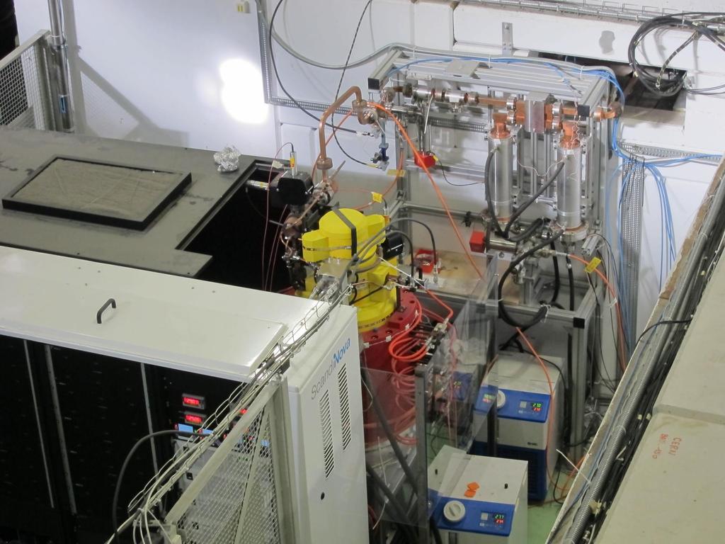
61 On the other side of the wall So we can now make the peak power. But what happens when we thump the accelerating structure with 50 MW? Something called vacuum breakdown. Very complicated and we address next. Xbox-2 and 3 bunker for accelerating structure tests
High acceleration gradient. Critical applications: Linear colliders e.g. ILC X-ray FELs e.g. DESY XFEL
 High acceleration gradient Critical applications: Linear colliders e.g. ILC X-ray FELs e.g. DESY XFEL Critical points The physical limitation of a SC resonator is given by the requirement that the RF magnetic
Room Temperature High Repetition Rate RF Structures for Light Sources
 Room Temperature High Repetition Rate RF Structures for Light Sources Sami G. Tantawi SLAC Claudio Pellegrini, R. Ruth, J. Wang. V. Dolgashev, C. Bane, Zhirong Huang, Jeff Neilson, Z. Li Outline Motivation
RF Cavity Design. Erk Jensen CERN BE/RF. CERN Accelerator School Accelerator Physics (Intermediate level) Darmstadt 2009
 Darmstadt 2009") RF Cavity Design Erk Jensen CERN BE/RF CERN Accelerator School Accelerator Physics (Intermediate level) Darmstadt 009 CAS Darmstadt '09 RF Cavity Design 1 Overview DC versus RF Basic equations: Lorentz
RF Cavity Design Erk Jensen CERN BE/RF CERN Accelerator School Accelerator Physics (Intermediate level) Darmstadt 009 CAS Darmstadt '09 RF Cavity Design 1 Overview DC versus RF Basic equations: Lorentz
(i) Determine the admittance parameters of the network of Fig 1 (f) and draw its - equivalent circuit.
 Determine the admittance parameters of the network of Fig 1 (f) and draw its - equivalent circuit.") I.E.S-(Conv.)-1995 ELECTRONICS AND TELECOMMUNICATION ENGINEERING PAPER - I Some useful data: Electron charge: 1.6 10 19 Coulomb Free space permeability: 4 10 7 H/m Free space permittivity: 8.85 pf/m Velocity
I.E.S-(Conv.)-1995 ELECTRONICS AND TELECOMMUNICATION ENGINEERING PAPER - I Some useful data: Electron charge: 1.6 10 19 Coulomb Free space permeability: 4 10 7 H/m Free space permittivity: 8.85 pf/m Velocity
PETS On-Off demonstration in CTF3
 CERN PETS On-Off demonstration in CTF3 Alexey Dubrovskiy 16.02.2012 Introduction The PETS On-Off mechanism is required for the future linear collider CLIC serving to a basic function permitting switching
International Technology Recommendation Panel. X-Band Linear Collider Path to the Future. RF System Overview. Chris Adolphsen
 International Technology Recommendation Panel X-Band Linear Collider Path to the Future RF System Overview Chris Adolphsen Stanford Linear Accelerator Center April 26-27, 2004 Delivering the Beam Energy
CERN EUROPEAN ORGANIZATION FOR NUCLEAR RESEARCH INVESTIGATION OF A RIDGE-LOADED WAVEGUIDE STRUCTURE FOR CLIC X-BAND CRAB CAVITY
 CERN EUROPEAN ORGANIZATION FOR NUCLEAR RESEARCH CLIC Note 1003 INVESTIGATION OF A RIDGE-LOADED WAVEGUIDE STRUCTURE FOR CLIC X-BAND CRAB CAVITY V.F. Khan, R. Calaga and A. Grudiev CERN, Geneva, Switzerland.
RF Design of Normal Conducting Deflecting Cavity
 RF Design of Normal Conducting Deflecting Cavity Valery Dolgashev (SLAC), Geoff Waldschmidt, Ali Nassiri (Argonne National Laboratory, Advanced Photon Source) 48th ICFA Advanced Beam Dynamics Workshop
LC Technology Hans Weise / DESY
 LC Technology Hans Weise / DESY All you need is... Luminosity! L σ 2 N e x σ y σ y σ x L n b f rep Re-writing reflects the LC choices... L P E b c. m. N e σ σ x y... beam power... bunch population... Ac-to-beam
Demonstration of exponential growth and saturation at VUV wavelengths at the TESLA Test Facility Free-Electron Laser. P. Castro for the TTF-FEL team
 Demonstration of exponential growth and saturation at VUV wavelengths at the TESLA Test Facility Free-Electron Laser P. Castro for the TTF-FEL team 100 nm 1 Å FEL radiation TESLA Test Facility at DESY
Development of a 20-MeV Dielectric-Loaded Accelerator Test Facility
 SLAC-PUB-11299 Development of a 20-MeV Dielectric-Loaded Accelerator Test Facility S.H. Gold, et al. Contributed to 11th Advanced Accelerator Concepts Workshop (AAC 2004), 06/21/2004--6/26/2004, Stony
FAST RF KICKER DESIGN
 FAST RF KICKER DESIGN David Alesini LNF-INFN, Frascati, Rome, Italy ICFA Mini-Workshop on Deflecting/Crabbing Cavity Applications in Accelerators, Shanghai, April 23-25, 2008 FAST STRIPLINE INJECTION KICKERS
Low-Level RF. S. Simrock, DESY. MAC mtg, May 05 Stefan Simrock DESY
 Low-Level RF S. Simrock, DESY Outline Scope of LLRF System Work Breakdown for XFEL LLRF Design for the VUV-FEL Cost, Personpower and Schedule RF Systems for XFEL RF Gun Injector 3rd harmonic cavity Main
Drive Beam Photo-injector Option for the CTF3 Nominal Phase
 CTF3 Review Drive Beam Photo-injector Option for the CTF3 Nominal Phase Motivation CTF3 Drive Beam Requirements CTF3 RF gun design The Laser (I. Ross / RAL) The Photocathode Cost estimate Possible schedule
Acceleration of High-Intensity Protons in the J-PARC Synchrotrons. KEK/J-PARC M. Yoshii
 Acceleration of High-Intensity Protons in the J-PARC Synchrotrons KEK/J-PARC M. Yoshii Introduction 1. J-PARC consists of 400 MeV Linac, 3 GeV Rapid Cycling Synchrotron (RCS) and 50 GeV Main synchrotron
Maurizio Vretenar Linac4 Project Leader EuCARD-2 Coordinator
 Maurizio Vretenar Linac4 Project Leader EuCARD-2 Coordinator Every accelerator needs a linac as injector to pass the region where the velocity of the particles increases with energy. At high energies (relativity)
R.K.YADAV. 2. Explain with suitable sketch the operation of two-cavity Klystron amplifier. explain the concept of velocity and current modulations.
 Question Bank DEPARTMENT OF ELECTRONICS AND COMMUNICATION SUBJECT- MICROWAVE ENGINEERING(EEC-603) Unit-III 1. What are the high frequency limitations of conventional tubes? Explain clearly. 2. Explain
High Gradient Studies at the NLC Test Accelerator (NLCTA)
") Chris Adolphsen High Gradient Studies at the NLC Test Accelerator (NLCTA) NLCTA Linac RF Unit (One of Two) Contributors C. Adolphsen, G. Bowden, D. Burke, J. Cornuelle, S. Dobert, V. Dolgashev, J. Frisch,
Chris Adolphsen High Gradient Studies at the NLC Test Accelerator (NLCTA) NLCTA Linac RF Unit (One of Two) Contributors C. Adolphsen, G. Bowden, D. Burke, J. Cornuelle, S. Dobert, V. Dolgashev, J. Frisch,
Pulsed 5 MeV standing wave electron linac for radiation processing
 PHYSICAL REVIEW SPECIAL TOPICS - ACCELERATORS AND BEAMS, VOLUME 7, 030101 (2004) Pulsed 5 MeV standing wave electron linac for radiation processing L. Auditore, R. C. Barnà, D. De Pasquale, A. Italiano,
ALICE SRF SYSTEM COMMISSIONING EXPERIENCE A. Wheelhouse ASTeC, STFC Daresbury Laboratory
 ALICE SRF SYSTEM COMMISSIONING EXPERIENCE A. Wheelhouse ASTeC, STFC Daresbury Laboratory ERL 09 8 th 12 th June 2009 ALICE Accelerators and Lasers In Combined Experiments Brief Description ALICE Superconducting
5kW DIODE-PUMPED TEST AMPLIFIER
 5kW DIODE-PUMPED TEST AMPLIFIER SUMMARY?Gain - OK, suggest high pump efficiency?efficient extraction - OK, but more accurate data required?self-stabilisation - Yes, to a few % but not well matched to analysis
Progress in High Gradient Accelerator Research at MIT
 Progress in High Gradient Accelerator Research at MIT Presented by Richard Temkin MIT Physics and Plasma Science and Fusion Center May 23, 2007 MIT Accelerator Research Collaborators MIT Plasma Science
3. (a) Derive an expression for the Hull cut off condition for cylindrical magnetron oscillator. (b) Write short notes on 8 cavity magnetron [8+8]
![3. (a) Derive an expression for the Hull cut off condition for cylindrical magnetron oscillator. (b) Write short notes on 8 cavity magnetron [8+8]](/thumbs/73/68588725.jpg "3. (a) Derive an expression for the Hull cut off condition for cylindrical magnetron oscillator. (b) Write short notes on 8 cavity magnetron [8+8]") Code No: RR320404 Set No. 1 1. (a) Compare Drift space bunching and Reflector bunching with the help of Applegate diagrams. (b) A reflex Klystron operates at the peak of n=1 or 3 / 4 mode. The dc power
Code No: RR320404 Set No. 1 1. (a) Compare Drift space bunching and Reflector bunching with the help of Applegate diagrams. (b) A reflex Klystron operates at the peak of n=1 or 3 / 4 mode. The dc power
REVIEW OF FAST BEAM CHOPPING F. Caspers CERN AB-RF-FB
 F. Caspers CERN AB-RF-FB Introduction Review of several fast chopping systems ESS-RAL LANL-SNS JAERI CERN-SPL Discussion Conclusion 1 Introduction Beam choppers are typically used for β = v/c values between
Behavior of the TTF2 RF Gun with long pulses and high repetition rates
 Behavior of the TTF2 RF Gun with long pulses and high repetition rates J. Baehr 1, I. Bohnet 1, J.-P. Carneiro 2, K. Floettmann 2, J. H. Han 1, M. v. Hartrott 3, M. Krasilnikov 1, O. Krebs 2, D. Lipka
Attosecond Diagnostics of Muti GeV Electron Beams Using W Band Deflectors
 Attosecond Diagnostics of Muti GeV Electron Beams Using W Band Deflectors V.A. Dolgashev, P. Emma, M. Dal Forno, A. Novokhatski, S. Weathersby SLAC National Accelerator Laboratory FEIS 2: Femtosecond Electron
SwissFEL Design and Status
 SwissFEL Design and Status Hans H. Braun Mini Workshop on Compact X ray Free electron Lasers Eastern Forum of Science and Technology Shanghai July 19, 2010 SwissFEL, the next large facility at PSI SwissFEL
Short-Pulse X-ray at the Advanced Photon Source Overview
 Short-Pulse X-ray at the Advanced Photon Source Overview Vadim Sajaev and Louis Emery Accelerator Operations and Physics Group Accelerator Systems Division Mini-workshop on Methods of Data Analysis in
CLIC Power Extraction and Transfer Structure. (2004)
") CLIC Power Extraction and Transfer Structure. (24) CLIC linac subunit layout: CLIC accelerating Structure (HDS) Main beam 3 GHz, 2 MW per structure Drive beam (64 A) CLIC Power Extraction and Transfer
CLIC Power Extraction and Transfer Structure. (24) CLIC linac subunit layout: CLIC accelerating Structure (HDS) Main beam 3 GHz, 2 MW per structure Drive beam (64 A) CLIC Power Extraction and Transfer
A High Gradient Coreless Induction Method of Acceleration
 A High Gradient Coreless Induction Method of Acceleration A. Krasnykh (SLAC National Accelerator Lab, USA) and A. Kardo-Sysoev (Ioffe PTI, St. Petersburg, Russia) ICFA Workshop on Novel Concepts, 2009
Converters for Cycling Machines
 Converters for Cycling Machines Neil Marks, DLS/CCLRC, Daresbury Laboratory, Warrington WA4 4AD, U.K. DC and AC accelerators; Contents suitable waveforms in cycling machines; the magnet load; reactive
INSTITUTE OF AERONAUTICAL ENGINEERING (Autonomous) Dundigal, Hyderabad
 Dundigal, Hyderabad") INSTITUTE OF AERONAUTICAL ENGINEERING (Autonomous) Dundigal, Hyderabad - 500 043 ELECTRONICS AND COMMUNICATION ENGINEERING TUTORIAL BANK Name : MICROWAVE ENGINEERING Code : A70442 Class : IV B. Tech I
INSTITUTE OF AERONAUTICAL ENGINEERING (Autonomous) Dundigal, Hyderabad - 500 043 ELECTRONICS AND COMMUNICATION ENGINEERING TUTORIAL BANK Name : MICROWAVE ENGINEERING Code : A70442 Class : IV B. Tech I
Stability Analysis of C-band 500-kW Klystron with Multi-cell. Output cavity
 Stability Analysis of C-band 5-kW Klystron with Multi-cell Output cavity Jihyun Hwang Department of Physics, POSTECH, Pohang 37673 Sung-Ju Park and Won Namkung Pohang Accelerator Laboratory, Pohang 37874
Experimental Plan for Testing the UNM Metamaterial Slow Wave Structure for High Power Microwave Generation
 Experimental Plan for Testing the UNM Metamaterial Slow Wave Structure for High Power Microwave Generation Kevin Shipman University of New Mexico Albuquerque, NM MURI Teleseminar August 5, 2016 1 Outline
Physics Requirements Document Document Title: SCRF 1.3 GHz Cryomodule Document Number: LCLSII-4.1-PR-0146-R0 Page 1 of 7
 Document Number: LCLSII-4.1-PR-0146-R0 Page 1 of 7 Document Approval: Originator: Tor Raubenheimer, Physics Support Lead Date Approved Approver: Marc Ross, Cryogenic System Manager Approver: Jose Chan,
NEW OPPORTUNITIES IN VACUUM ELECTRONICS USING PHOTONIC BAND GAP STRUCTURES
 NEW OPPORTUNITIES IN VACUUM ELECTRONICS USING PHOTONIC BAND GAP STRUCTURES J. R. Sirigiri, C. Chen, M. A. Shapiro, E. I. Smirnova, and R. J. Temkin Plasma Science and Fusion Center Massachusetts Institute
HIGH-GRADIENT TESTING OF SINGLE-CELL TEST CAVITIES AT KEK / NEXTEF
 Presented at the 13th Annual Meeting of Particle Accelerator Society of Japan, Aug. 2016 (Paper ID: MOP015) 1 HIGH-GRADIENT TESTING OF SINGLE-CELL TEST CAVITIES AT KEK / NEXTEF Tetsuo Abe, Yoshio Arakida,
04th - 16th August, th International Nathiagali Summer College 1 CAVITY BASICS. C. Serpico
 39th International Nathiagali Summer College 1 CAVITY BASICS C. Serpico 39th International Nathiagali Summer College 2 Outline Maxwell equations Guided propagation Rectangular waveguide Circular waveguide
FLASH at DESY. FLASH. Free-Electron Laser in Hamburg. The first soft X-ray FEL operating two undulator beamlines simultaneously
 FLASH at DESY The first soft X-ray FEL operating two undulator beamlines simultaneously Katja Honkavaara, DESY for the FLASH team FEL Conference 2014, Basel 25-29 August, 2014 First Lasing FLASH2 > First
Compact Radio Frequency Technology for Applications in Cargo and Global
 Compact Radio Frequency Technology for Applications in Cargo and Global Security Peter McIntosh STFC Daresbury Laboratory CLASP Security Event Tuesday 5 th July 2011, London Compact RF Technologies S-band
A HIGH EFFICIENCY 17GHz TW CHOPPERTRON
 1 SLAC 07 A HIGH EFFICIENCY 17GHz TW CHOPPERTRON J. Haimson and B. Mecklenburg Work performed under the auspices of the U.S. Department of Energy SBIR Grant No.DE-FG02-06ER84468 2 SLAC 07 Figure 1. Centerline
HIGH POWER COUPLER FOR THE TESLA TEST FACILITY
 Abstract HIGH POWER COUPLER FOR THE TESLA TEST FACILITY W.-D. Moeller * for the TESLA Collaboration, Deutsches Elektronen-Synchrotron DESY, D-22603 Hamburg, Germany The TeV Energy Superconducting Linear
Studies of vacuum discharges in the CLIC accelerating structure
 Faculty of Engineering - LTH Master s Thesis Studies of vacuum discharges in the CLIC accelerating structure Author: Anton Tropp, Lund University June 22, 2016 Supervisor: Anders Karlsson, Lund University
EC 1402 Microwave Engineering
 SHRI ANGALAMMAN COLLEGE OF ENGINEERING & TECHNOLOGY (An ISO 9001:2008 Certified Institution) SIRUGANOOR,TRICHY-621105. DEPARTMENT OF ELECTRONICS AND COMMUNICATION ENGINEERING EC 1402 Microwave Engineering
Module IV, Lecture 2 DNP experiments and hardware
 Module IV, Lecture 2 DNP experiments and hardware tunnel diodes, Gunn diodes, magnetrons, traveling-wave tubes, klystrons, gyrotrons Dr Ilya Kuprov, University of Southampton, 2013 (for all lecture notes
Development of a 20 MeV Dielectric-Loaded Test Accelerator
 SLAC-PUB-12454 Development of a 20 MeV Dielectric-Loaded Test Accelerator Steven H. Gold*, Allen K. Kinkead, Wei Gai, John G. Power, Richard Konecny, Chunguang Jing, Jidong Long, Sami G. Tantawi, Christopher
3 General layout of the XFEL Facility
 3 General layout of the XFEL Facility 3.1 Introduction The present chapter provides an overview of the whole European X-Ray Free-Electron Laser (XFEL) Facility layout, enumerating its main components and
Beam Diagnostics, Low Level RF and Feedback for Room Temperature FELs. Josef Frisch Pohang, March 14, 2011
 Beam Diagnostics, Low Level RF and Feedback for Room Temperature FELs Josef Frisch Pohang, March 14, 2011 Room Temperature / Superconducting Very different pulse structures RT: single bunch or short bursts
Prospects for an Inductive Output Tube (IOT) Based Source
 Based Source") Prospects for an Inductive Output Tube (IOT) Based Source Brian Beaudoin February, 10 2016 Institute for Research in Electronics & Applied Physics 1 https://en.wikipedia.org/wiki/high_frequency_active_auroral_research_program.
Prospects for an Inductive Output Tube (IOT) Based Source Brian Beaudoin February, 10 2016 Institute for Research in Electronics & Applied Physics 1 https://en.wikipedia.org/wiki/high_frequency_active_auroral_research_program.
X-Band Linear Collider Report*
 SLAC DOE Program Review X-Band Linear Collider Path to the Future X-Band Linear Collider Report* D. L. Burke NLC Program Director * Abstracted from recent presentations to the International Technical Recommendation
Multimoded RF Systems for Future Linear Colliders. Sami G. Tantawi
 Multimoded RF Systems for Future Linear Colliders Sami G. Tantawi Acknowledgment This work is a result of a continuous effort by many researches and engineers over many years. In particular, The efforts
New SLED 3 system for Multi-mega Watt RF compressor. Chen Xu, Juwen Wang, Sami Tantawi
 New SLED 3 system for Multi-mega Watt RF compressor Chen Xu, Juwen Wang, Sami Tantawi SLAC National Accelerator Laboratory, Stanford University, Stanford, CA 94309, USA Electronic address: chenxu@slac.stanford.edu
JUAS 2018 LINACS. Jean-Baptiste Lallement, Veliko Dimov BE/ABP CERN.
 LINACS Jean-Baptiste Lallement, Veliko Dimov BE/ABP CERN jean-baptiste.lallement@cern.ch http://jlalleme.web.cern.ch/jlalleme/juas2018/ Credits Much material is taken from: Thomas Wangler, RF linear accelerators
Illinois. I Physics. Investigation of TESLA Damping Ring Kickers using the A0 Photoinjector Beam
 George Gollin, Investigation of TESLA Damping Ring Kickers using the A0 hotoinjector Beam 1 I hysics Investigation of TESLA Damping Ring Kickers using the A0 hotoinjector Beam George Gollin Department
St.MARTIN S ENGINEERING COLLEGE Dhulapally, Secunderabad
 St.MARTIN S ENGINEERING COLLEGE Dhulapally, Secunderabad 500014. Department of Electronics and Communication Engineering SUB: MICROWAVE ENGINEERING SECTION: ECE IV A & B NAME OF THE FACULTY: S RAVI KUMAR,T.SUDHEER
Project of RF System for 2.2 GeV Electron Storage Ring Zelenograd SR Source.
 Project of RF System for 2.2 GeV Electron Storage Ring Zelenograd SR Source. I.K. Sedlyarov V.S. Arbuzov, E.I Gorniker, A.A. Kondakov, S.A. Krutikhin, G.Ya. Kurkin, I.V.Kuptsov, V.N. Osipov, V.M. Petrov,
ELECTRON LINACS. Alessandro Fabris. Elettra-Sincrotrone Trieste S.C.p.A, Italy. 39 th International Nathiagali Summer College 4 th 9 th August 2014
 ELECTRON LINACS Elettra-Sincrotrone Trieste S.C.p.A, Italy 39 th International Nathiagali Summer College 4 th 9 th August 2014 2 OVERVIEW Introduction Travelling wave structures Standing wave structures
Performance of the Prototype NLC RF Phase and Timing Distribution System *
 SLAC PUB 8458 June 2000 Performance of the Prototype NLC RF Phase and Timing Distribution System * Josef Frisch, David G. Brown, Eugene Cisneros Stanford Linear Accelerator Center, Stanford University,
Illinois. I Physics. Fourier engineering: progress on alternative TESLA kickers
 George Gollin, Fourier engineering Victoria, LC 2004 1 I hysics Fourier engineering: progress on alternative TESLA kickers George Gollin Department of hysics University of at Urbana-Champaign USA George
Superstructures; First Cold Test and Future Applications
 Superstructures; First Cold Test and Future Applications DESY: C. Albrecht, V. Ayvazyan, R. Bandelmann, T. Büttner, P. Castro, S. Choroba, J. Eschke, B. Faatz, A. Gössel, K. Honkavaara, B. Horst, J. Iversen,
Gyroklystron Research at CCR
 Gyroklystron Research at CCR RLI@calcreek.com Lawrence Ives, Michael Read, Jeff Neilson, Philipp Borchard and Max Mizuhara Calabazas Creek Research, Inc. 20937 Comer Drive, Saratoga, CA 95070-3753 W. Lawson
New apparatus for precise synchronous phase shift measurements in storage rings 1
 New apparatus for precise synchronous phase shift measurements in storage rings 1 Boris Podobedov and Robert Siemann Stanford Linear Accelerator Center, Stanford University, Stanford, CA 94309 Measuring
The European Spallation Source. Dave McGinnis Chief Engineer ESS\Accelerator Division IVEC 2013
 The European Spallation Source Dave McGinnis Chief Engineer ESS\Accelerator Division IVEC 2013 Overview The European Spallation Source (ESS) will house the most powerful proton linac ever built. The average
Detailed Design Report
 Detailed Design Report Chapter 2 MAX IV 3 GeV Storage Ring 2.6. The Radio Frequency System MAX IV Facility CHAPTER 2.6. THE RADIO FREQUENCY SYSTEM 1(15) 2.6. The Radio Frequency System 2.6. The Radio Frequency
Project X Cavity RF and mechanical design. T. Khabiboulline, FNAL/TD/SRF
 Project X Cavity RF and mechanical design T. Khabiboulline, FNAL/TD/SRF TTC meeting on CW-SRF, 2013 Project X Cavity RF and mechanical design T 1 High ß Low ß 0.5 HWR SSR1 SSR2 0 1 10 100 1 10 3 1 10 4
On the RF system of the ILC
 On the RF system of the ILC Sami G. Tantawi Chris Nantista Valery Dolgashev Jiquan Guo SLAC Outline This talk is a collection of thoughts about the rf system based on our experience with X-band system!
Experiment-4 Study of the characteristics of the Klystron tube
 Experiment-4 Study of the characteristics of the Klystron tube OBJECTIVE To study the characteristics of the reflex Klystron tube and to determine the its electronic tuning range EQUIPMENTS Klystron power
Calibrating the Cavity Voltage. Presentation of an idea
 Calibrating the Cavity Voltage. Presentation of an idea Stefan Wilke, DESY MHF-e 21st ESLS rf meeting Kraków, 15th/16th nov 2017 Accelerators at DESY. linear and circular Page 2 Accelerators at DESY. linear
NLC - The Next Linear Collider Project. NLC Update. CLIC Group. CERN September D. L. Burke SLAC
 NLC Update CLIC Group September 2003 SLAC Configuration Electron Injector 560 m ~10 m 170 m Pre-Linac 6 GeV (S) Compressor 136 MeV (L) 2 GeV (S) ~100 m 0.6 GeV (X) ~20 m Compressor Damping Ring e (UHF)
MULTIPLE EXTRACTION CAVITIES FOR HIGH POWER KLYSTRONS*
 SLAC-PUB-6011 Rev. February 1993 (4 MULTIPLE EXTRACTION CAVITIES FOR HIGH POWER KLYSTRONS* T. G. Lee Stanford Linear Accelerator Center Stanford University, Stanford, CA 94309 ABSTRACT The design, performance,
The TESLA Linear Collider. Winfried Decking (DESY) for the TESLA Collaboration
 for the TESLA Collaboration") The TESLA Linear Collider Winfried Decking (DESY) for the TESLA Collaboration Outline Project Overview Highlights 2000/2001 Publication of the TDR Cavity R&D TTF Operation A0 and PITZ TESLA Beam Dynamics
The TESLA Linear Collider Winfried Decking (DESY) for the TESLA Collaboration Outline Project Overview Highlights 2000/2001 Publication of the TDR Cavity R&D TTF Operation A0 and PITZ TESLA Beam Dynamics
Tendencies in the Development of High-Power Gyrotrons
 Tendencies in the Development of High-Power Gyrotrons G.G.Denisov Institute of Applied Physics Russian Academy of Sciences Ltd. Nizhny Novgorod, Russia JAERI/TOSHIBA / FZK/THALES CPI/GA Gyro-devices Extraordinary
THE CRYOGENIC SYSTEM OF TESLA
 THE CRYOGENIC SYSTEM OF TESLA S. Wolff, DESY, Notkestr. 85, 22607 Hamburg, Germany for the TESLA collaboration Abstract TESLA, a 33 km long 500 GeV centre-of-mass energy superconducting linear collider
Electro-Optical Measurements at the Swiss Light Source (SLS) Linac at the PSI. First Results
 Linac at the PSI. First Results") Electro-Optical Measurements at the Swiss Light Source (SLS) Linac at the PSI First Results Overview motivation electro-optical sampling general remarks experimental setup synchronisation between TiSa-laser
Electro-Optical Measurements at the Swiss Light Source (SLS) Linac at the PSI First Results Overview motivation electro-optical sampling general remarks experimental setup synchronisation between TiSa-laser
ECRH on the Levitated Dipole Experiment
 ECRH on the Levitated Dipole Experiment S. Mahar, J. Kesner, A.C. Boxer, J.E. Ellsworth, I. Karim, A. Roach MIT PSFC A.K. Hansen, D.T. Garnier, M.E. Mauel, E.E.Ortiz Columbia University Presented at the
NanoBPM tests in the ATF extraction line
 NLC - The Next Linear Collider Project NanoBPM tests in the ATF extraction line Calibrate movers (tilters) and BPM s Understand and test dynamic range and resolution June 2003 Marc Ross What are the uses
Experimental Study on W-Band ( GHz) Oversized Surface Wave Oscillator Driven by Weakly Relativistic Electron Beams )
 Oversized Surface Wave Oscillator Driven by Weakly Relativistic Electron Beams )") Experimental Study on W-Band (75-110 GHz) Oversized Surface Wave Oscillator Driven by Weakly Relativistic Electron Beams ) Min Thu SAN, Kazuo OGURA, Kiyoyuki YAMBE, Yuta ANNAKA, Shaoyan GONG, Jun KAWAMURA,
Experimental Study on W-Band (75-110 GHz) Oversized Surface Wave Oscillator Driven by Weakly Relativistic Electron Beams ) Min Thu SAN, Kazuo OGURA, Kiyoyuki YAMBE, Yuta ANNAKA, Shaoyan GONG, Jun KAWAMURA,
3.10 Lower Hybrid Current Drive (LHCD) System
 System") 3.10 Lower Hybrid Current Drive (LHCD) System KUANG Guangli SHAN Jiafang 3.10.1 Purpose of LHCD program 3.10.1.1 Introduction Lower hybrid waves are quasi-static electric waves propagated in magnetically
3.10 Lower Hybrid Current Drive (LHCD) System KUANG Guangli SHAN Jiafang 3.10.1 Purpose of LHCD program 3.10.1.1 Introduction Lower hybrid waves are quasi-static electric waves propagated in magnetically
PRINCIPLES OF RADAR. By Members of the Staff of the Radar School Massachusetts Institute of Technology. Third Edition by J.
 PRINCIPLES OF RADAR By Members of the Staff of the Radar School Massachusetts Institute of Technology Third Edition by J. Francis Reintjes ASSISTANT PBOFESSOR OF COMMUNICATIONS MASSACHUSETTS INSTITUTE
CERN European Organization for Nuclear Research European Laboratory for Particle Physics
 CERN European Organization for Nuclear Research European Laboratory for Particle Physics CLIC Note 592 CERN-OPEN-2004-015 14/06/2004 HIGH-POWER MICROWAVE PULSE COMPRESSION OF KLYSTRONS BY PHASE-MODULATION
H. Weise, Deutsches Elektronen-Synchrotron, Hamburg, Germany for the XFEL Group
 7+(7(6/$;)(/352-(&7 H. Weise, Deutsches Elektronen-Synchrotron, Hamburg, Germany for the XFEL Group $EVWUDFW The overall layout of the X-Ray FEL to be built in international collaboration at DESY will
Bioimaging of cells and tissues using accelerator-based sources
 Analytical and Bioanalytical Chemistry Electronic Supplementary Material Bioimaging of cells and tissues using accelerator-based sources Cyril Petibois, Mariangela Cestelli Guidi Main features of Free
Advance on High Power Couplers for SC Accelerators
 Advance on High Power Couplers for SC Accelerators Eiji Kako (KEK, Japan) IAS conference at Hong Kong for High Energy Physics, 2017, January 23th Eiji KAKO (KEK, Japan) IAS at Hong Kong, 2017 Jan. 23 1
MICROWAVE MICROWAVE TRAINING BENCH COMPONENT SPECIFICATIONS:
 Microwave section consists of Basic Microwave Training Bench, Advance Microwave Training Bench and Microwave Communication Training System. Microwave Training System is used to study all the concepts of
Market Survey. Technical Description. Supply of Medium Voltage Pulse Forming System for Klystron Modulators
 EDMS No. 1972158 CLIC Drive Beam Klystron Modulator Group Code: TE-EPC Medium Voltage Pulse Forming System for CLIC R&D Market Survey Technical Description Supply of Medium Voltage Pulse Forming System
Energy Recovering Linac Issues
 Energy Recovering Linac Issues L. Merminga Jefferson Lab EIC Accelerator Workshop Brookhaven National Laboratory February 26-27, 2002 Outline Energy Recovery RF Stability in Recirculating, Energy Recovering
UNIT - V WAVEGUIDES. Part A (2 marks)
") Part A (2 marks) UNIT - V WAVEGUIDES 1. What is the need for guide termination? (Nov / Dec 2011) To avoid reflection loss. The termination should provide a wave impedance equal to that of the transmission
Part A (2 marks) UNIT - V WAVEGUIDES 1. What is the need for guide termination? (Nov / Dec 2011) To avoid reflection loss. The termination should provide a wave impedance equal to that of the transmission
I.E.S-(Conv.)-1996 Some useful data:
-1996 Some useful data:") I.E.S-(Conv.)-1996 ELECTRONICS AND TELECOMMUNICATION ENGINEERING PAPER - I Time allowed: 3 Hours Maximum Marks : 200 Candidates should attempt question ONE which is compulsory and any FOUR of the remaining
I.E.S-(Conv.)-1996 ELECTRONICS AND TELECOMMUNICATION ENGINEERING PAPER - I Time allowed: 3 Hours Maximum Marks : 200 Candidates should attempt question ONE which is compulsory and any FOUR of the remaining
High Rep-Rate KrF Laser Development and Intense Pulse Interaction Experiments for IFE*
 High Rep-Rate KrF Laser Development and Intense Pulse Interaction Experiments for IFE* Y. Owadano, E. Takahashi, I. Okuda, I. Matsushima, Y. Matsumoto, S. Kato, E. Miura and H.Yashiro 1), K. Kuwahara 2)
RF Systems I. Erk Jensen, CERN BE-RF
 RF Systems I Erk Jensen, CERN BE-RF Introduction to Accelerator Physics, Prague, Czech Republic, 31 Aug 12 Sept 2014 Definitions & basic concepts db t-domain vs. ω-domain phasors 8th Sept, 2014 CAS Prague
Design and RF Measurements of an X-band Accelerating Structure for the Sparc Project
 Design and RF Measurements of an X-band Accelerating Structure for the Sparc Project INFN-LNF ; UNIVERSITY OF ROME LA SAPIENZA ; INFN - MI Presented by BRUNO SPATARO Erice, Sicily, October 9-14; 2005 SALAF
30 GHz rf components for CTF3 (and CLIC) next part. I. Syratchev
 next part. I. Syratchev") 3 GHz rf components for CTF3 (and CLIC) next part I. Syratchev 3 GHz overmoded waveguide components (GYCOM, Russia) Mode converter 4.86x5 Taper Mitered bend.75.5 T 5 9.985 Measured losses per mode converter
3 GHz rf components for CTF3 (and CLIC) next part I. Syratchev 3 GHz overmoded waveguide components (GYCOM, Russia) Mode converter 4.86x5 Taper Mitered bend.75.5 T 5 9.985 Measured losses per mode converter
A Synchrotron Phase Detector for the Fermilab Booster
 FERMILAB-TM-2234 A Synchrotron Phase Detector for the Fermilab Booster Xi Yang and Rene Padilla Fermi National Accelerator Laboratory Box 5, Batavia IL 651 Abstract A synchrotron phase detector is diagnostic
A Design Study of a 100-MHz Thermionic RF Gun for the ANL XFEL-O Injector
 A Design Study of a 100-MHz Thermionic RF Gun for the ANL XFEL-O Injector A. Nassiri Advanced Photon Source For ANL XFEL-O Injector Study Group M. Borland (ASD), B. Brajuskovic (AES), D. Capatina (AES),
Borut Baricevic. Libera LLRF. 17 September 2009
 Borut Baricevic Libera LLRF borut.baricevic@i-tech.si 17 September 2009 Outline Libera LLRF introduction Libera LLRF system topology Signal processing structure GUI and signal acquisition RF system diagnostics
REVIEW OF HIGH POWER CW COUPLERS FOR SC CAVITIES. S. Belomestnykh
 REVIEW OF HIGH POWER CW COUPLERS FOR SC CAVITIES S. Belomestnykh HPC workshop JLAB, 30 October 2002 Introduction Many aspects of the high-power coupler design, fabrication, preparation, conditioning, integration
Commissioning of the ALICE SRF Systems at Daresbury Laboratory Alan Wheelhouse, ASTeC, STFC Daresbury Laboratory ESLS RF 1 st 2 nd October 2008
 Commissioning of the ALICE SRF Systems at Daresbury Laboratory Alan Wheelhouse, ASTeC, STFC Daresbury Laboratory ESLS RF 1 st 2 nd October 2008 Overview ALICE (Accelerators and Lasers In Combined Experiments)
Status and Plans for the 805 MHz Box Cavity MuCool RF Workshop III 07/07/09 Al Moretti
 Status and Plans for the 805 MHz Box Cavity MuCool RF Workshop III 07/07/09 Al Moretti 7/6/2009 1 Outline : Description of the Box cavity Concept. Box Cavity Summary Plans. HFSS Models of orthogonal and
Status of the MAX IV RF systems. PPT-mall 2
 Status of the MAX IV RF systems PPT-mall 2 Lars Malmgren Med linje On Behalf of the MAX IV RF Group Åke Andersson, Joel Andersson, Richard Grandford, Sven-Olof Heed, Per Lilja, Dionis Kumbaro, Lars Malmgren,
Dhanalakshmi College of Engineering Department of ECE EC6701 RF and Microwave Engineering Unit 4 Part A
 Dhanalakshmi College of Engineering Department of ECE EC6701 RF and Microwave Engineering Unit 4 Part A 1. What is magnetron? [N/D-16] an electron tube for amplifying or generating microwaves, with the