GLR43308 and GLR2708. Setup and programming instructions. for the 8 channel Gigalink receiver. Programming Videos
|
|
|
- Clifton Dennis
- 5 years ago
- Views:
Transcription


1 GLR43308 and GLR2708 Setup and programming instructions for the 8 channel Gigalink receiver Programming Videos
2 NOTES IMPORTANT WARNING AND SAFETY INSTRUCTIONS All installations and testing must be done only after reading and understanding all instructions carefully. All wirings should be done only by trained technical personnel. Failing to follow instructions and the safety warnings may result in serious injury and/or damage to property. Elsema Pty Ltd shall not be liable for any injury, damage, cost, expense or any claim whatsoever to any person or property which may result from improper use or installation of this product. Risk in the goods purchased shall unless otherwise agreed in written pass to the buyer upon delivery of the goods. Any figures or estimates given for performance of goods are based upon the company s experience and is what the company obtains on tests. The company will not accept liability for failure to comply with the figures or estimates due to the nature of variable conditions affecting for example Radio Remote Controls. Please keep this setup instruction for future reference. 2 For detailed information visit
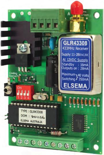
3 GLR43308 and GLR2708 Setup and programming instructions for the 8 channel Gigalink receiver FEATURES Eight channel receiver with 8 open collector outputs Supply voltage can be AC or DC Low current consumption Over 4 billion code combinations Crystal controlled for high reliability Can store unlimited number of transmitters Uses micro-controller technology that can be re-programmed to suit unique applications Momentary, latching and security latching modes are all user selectable Optional QM100 bracket available for easy mounting to cases or walls E version receiver available with a weatherproof case DESCRIPTION This Gigalink receiver gives you eight open collector outputs switching to ground with a capacity of 125mA 40 VDC each. Each open collector output is protected with a diode to stop any EMF from getting to the receiver. The receiver s micro-controller can store unlimited number of transmitters with a high security level using the encrypted 32-bit digital code. Included with the receiver is the Gigalink programming cable. TECHNICAL DATA Supply Voltage Frequencies for GLR43308 Frequency for GLR2708 Output Antenna Compatible Transmitters VDC, VAC. Can use Elsema DC or AC power supply, 12PP1000 or 24PP (Standard), , , MHz MHz Eight open collector outputs. ANT433 series (433MHz Series) or ANT27 series (27MHz Series) GLT433 MHz series, GLT27 MHz series Enter the World of Wireless 3
4 PROGRAMMING INSTRUCTIONS The transmitter and receiver can be multi or single channel programmed. Multi-channel Programming This is used to program all channels from a multi-channel receiver to a multi-channel transmitter. Multichannel programming can be achieved by following the steps below: Step 1: Step 2: Step 3: Step 4: Step 5: Connect power to the GIGALINK receiver. Make sure all switches on the mode dipswitch are off. Momentarily short the two CC pins on the receiver board. This sets all the channels to a random code. If there are transmitters previously programmed, they will have to be re-programmed when CC pins are shorted. Do not do this step if you want to keep previously programmed transmitters. Connect the multi-channel transmitter to the multi-channel receiver by inserting the GIGALINK cable into the transmitters and receivers 2.5-mm Coding socket. (This will activate the programming mode and is indicated by the red light (LED), on the transmitter that must remain on ). Activate any two channels simultaneously on the multi-channel transmitter for one second, LED should blink twice to confirm code programming and then switch off. Disconnect GIGALINK cable. Repeat steps 3 to 5 to program another multi-channel transmitter. If you are programming another transmitter, do not short out the CC pins. Shorting out the CC pins will delete all previously programmed transmitters. 4 For detailed information visit
5 SINGLE CHANNEL PROGRAMMING This is used for programming one channel at a time to the transmitter. Single channel programming can be achieved by following the steps below: Step 1: Step 2: Step 3: Connect power to the GIGALINK receiver. Make sure all switches on the mode dipswitch are off. Momentarily short the two CC pins on the receiver board. This sets all the channels to a random code. If there are transmitters previously programmed, they will have to be re-programmed when CC pins are shorted. Select the receiver channel, to be programmed, by setting the 4-way dipswitch. See dipswitch table below. Dipswitch Setting Receiver Channel Off Off Off 1 On Off Off 2 Off On Off 3 On On Off 4 Off Off On 5 On Off On 6 Off On On 7 On On On 8 Step 4: Step 5: Step 6: Connect the transmitter to the receiver by inserting the GIGALINK cable into the transmitters and receivers 2.5-mm Coding socket. (This will activate the programming mode and is indicated by the red light (LED) on the transmitter that must remain on ). Activate one of the selected channels on the transmitter for approximately one second, LED should blink twice to confirm code programming and then switch off. Disconnect GIGALINK cable. Repeat steps 3 to 6 to program another transmitter channel. If you are programming another transmitter, do not short out the CC pins. Shorting out the CC pins will delete all previously programmed transmitters. Enter the World of Wireless 5


6 SPECIAL PROGRAMMING FEATURE FOR GIGALINK Forward Programming GIGALINK receivers have an additional programming feature, known as forward programming. This feature allows the user to program the transmitter code into the receivers. This will enable the transmitters to activate unlimited number of receivers simultaneously. Step 1: Step 2: Step 3: Step 4: Step 5: Step 6: Connect power to the receiver and transmitter. Place a jumper across the CC pins of the receiver. Connect the transmitter and receiver using the coding cable. Press the transmitter button for 2 seconds. Remove the coding cable. Remove the jumper from the CC pin. The receiver is now programmed with the transmitter s code. Repeat the above steps to program another receiver. ACCESSORIES AVAILABLE Weatherproof Case for receiver unit Gigalink Coding Cable For coding Gigalink transmitters to receivers SUPREG12, SUPREG24 Supply and Battery charger. Ideal for charging backup battery and supplying the receiver. Suitable Antennas ANT27 series (27MHz Series) or ANT433 series (433MHz Series) Suitable Power packs 12PP-1000, 12V DC 1000mA 24PP, 24V DC 500mA. QM100 Quick Mount for easy mounting of receivers on walls. 6 For detailed information visit
7 MODE SETTING When the GIGALINK cable is disconnected the 4-way dipswitch functions as a mode selector for the output. User should set the receiver mode correctly. See below table for different mode setting. Dipswitch Mode Settings The output relay will respond in the following manner when receiving the correct signal from a transmitter All Momentary : Relay on, only while correct signal is received All Latching : Outputs alternate at every correct incoming signal Momentary & Latching : Outputs 1-4 are momentary & 5-8 are latching Security Latching on : Outputs will be on until supply to receiver is momentarily interrupted Momentary & Latching : Outputs 1-6 are momentary & 7-8 are latching Momentary & Latching : Outputs 1-2 are momentary & 3-8 are latching Momentary & Latching : Outputs 1-3 are momentary & 4-8 are latching Security Latching on : Output 1 is security latching & 2-8 are momentary * Dipswitch 4 is reserved Enter the World of Wireless 7


 9609 4668 Fax: +61 (2) 9725 2663 or you can")
8 TROUBLESHOOTING This section contains helpful troubleshooting tips and solutions. Symptom Receiver not responding to transmitter after programming. Transmitter activates wrong channel on a multi-channel receiver. Transmitter has short range. LED is flashing on the transmitter. Solution Try to program the transmitter again, but this time with the battery connected to the transmitter. Check if GIGALINK cable is inserted correctly. Wrong dipswitch setting while programming the receiver. Use the dipswitch table and program again. Check receiver antenna connection. If you are using a shielded coax cable, check that the shield is connected to the negative and the coaxial core to the antenna terminal. Replace battery. CUSTOMER SUPPORT If your transmitter and receiver are still not operating properly, contact Elsema s support office at: Phone: +61 (2) Fax: +61 (2) or you can visit our web site at for the latest updates. BLDF045 ELSEMA PTY LTD 31 Tarlington Place Smithfield NSW 2164 Australia P F W Local Distributor
The combination of FFH and MCR technology brings you a very sophisticated receiver yet easy to use.
 MCR91512SS and MCR91512R 12-Channel, 915MHz Receiver with Frequency Hopping Features Frequency hopping between 915 to 928MHz Eight channels with simultaneous channel reception Digital Coding, 12-way dipswitch
ELSEMA GLR Applications Automatic gates. Security systems. Timer controlled outputs. Simple on/off functions.
 GLR43301 Single Channel 433MHz Gigalink Receiver with Timer Controlled Relay Output Features Wide supply connection 10.0 to 28.0 Volts AC/DC Highly sensitive receiver input stage. When used with GLT433
MCR91508POS 8 Channel receiver with 8 positive output switching
 MCR91508R, MCR91508POS and MCR91508SS 8-Channel, 915MHz Receiver with Frequency Hopping Features Frequency hopping between 915 to 927MHz Eight channels with simultaneous channel reception Digital Coding,
ELSEMA 1-Channel 433MHz Receiver with 16A Relay Output- GLR
 GLR43301240 1-Channel 433MHz Gigalink, Receiver with Mains AC Supply Features Supply voltage 240VAC (also available in 110-120VAC supply for international markets) High efficiency toroidal transformer
ELSEMA 1,2,3,4,8 -Channel 433MHz GIGALINK Transmitter GLT43300,GLT43301,GLT43302,GLT43303,GLT43304,GLT43308
 433MHz HAND HELD GIGALINK TRANSMITTERS GLT43300, GLT43301, GLT43302, GLT43303, GLT43304 and GLT43308 Features One, two, three, four & eight buttons. More than four billion code combinations Ability to
FMR ELSEMA 1-Channel 151MHz Receiver - FMR15101
 FMR15101 1-Channel 151MHz Receiver Features Single channel receiver with relay output Supply voltage can be AC or DC Low current consumption Built-in noise or signal strength indicator User can select
FMR Description
 1-Channel 151MHz FM Receiver with mains AC supply Features Supply voltage 240VAC (also available in 110-120VAC supply for international markets) High efficiency toroidal transformer High capacity output
ELSEMA 1,2,3,4,8 -Channel 433MHz,25mWatt Transmitter
 ELSEMA GLT4330112E, GLT4330212E, GLT4330412E, GLT4330812E, GLT4330812NC 433MHz, 25mW GIGALINK TRANSMITTERS Features One, two, four & eight channels. Wide supply connection 11.0 to 24.0 Volts DC. More than
MCR91501R 1-Channel, 915MHz Receiver with Frequency Hopping
 MCR91501R 1-Channel, 915MHz Receiver with Frequency Hopping Features Frequency hopping between 915 to 928MHz Digital Coding, 12-way dipswitch or encrypted coding Crystal Controlled for high stability and
ELSEMA 1,2,3,4,8 -Channel 433MHz GIGALINK Transmitter GLT43300,GLT43301,GLT43302,GLT43303,GLT43304,GLT43308
 GLT43300/1/2/3/4/8 433MHz HAND HELD GIGALINK TRANSMITTERS Features One, two, three, four & eight channels. More than four billion code combinations and no dipswitch visible, enabling it to be used for
FMR ELSEMA 2-Channel 151MHz Receiver - FMR15102
 FMR15102 2-Channel 151MHz Receiver Features Two channel receiver with relay outputs Supply voltage can be AC or DC Low current consumption Built-in noise or signal strength indicator User can select 8
ELSEMA. GLR2701 Single Channel 27MHz Gigalink Receiver with Timer Controlled Relay Output
 GLR2701 Single Channel 27MHz Gigalink Receiver with Timer Controlled Relay Output ELSEMA Features Wide supply connection 11.0 to 28.0 Volts AC/DC Highly sensitive receiver input stage. When used with GLT27.
MD12-2 Metal Loop Detector
 MD12-2 Metal Loop Detector Features Supply 12VDC Adjustable sensitivity (8 levels via dip switch) 2 x Relay outputs (each can be configured individually) Power up and loop activation LED indicator. Industry
FMT15101E, FMT15102E, FMT15104E, FMT15108E (Enclosed version) FMT15108 (No Case version)
 FMT15108 (No Case version)") FMT15101E, FMT15102E, FMT15104E, FMT15108E (Enclosed version) FMT15108 (No Case version) 1, 2, 4, 8-Channel 151MHz Transmitter Features Long range up to 5km. 100mW Transmitter with current consumption
FMT15101E, FMT15102E, FMT15104E, FMT15108E (Enclosed version) FMT15108 (No Case version) 1, 2, 4, 8-Channel 151MHz Transmitter Features Long range up to 5km. 100mW Transmitter with current consumption
FMT15101E, FMT15102E, FMT15104E, FMT15108E (Enclosed version) FMT15101, FMT15102, FMT15104, FMT15108 (No Case version)
 FMT15101, FMT15102, FMT15104, FMT15108 (No Case version)") FMT15101E, FMT15102E, FMT15104E, FMT15108E (Enclosed version) FMT15101, FMT15102, FMT15104, FMT15108 1, 2, 4, 8-Channel 151MHz Transmitter Features Long range up to 5km. 100mW Transmitter with current
FMT15101E, FMT15102E, FMT15104E, FMT15108E (Enclosed version) FMT15101, FMT15102, FMT15104, FMT15108 1, 2, 4, 8-Channel 151MHz Transmitter Features Long range up to 5km. 100mW Transmitter with current
FMR MHz Receiver with Two Relay Outputs
 FMR-202 27MHz Receiver with Two Relay Features Crystal Controlled 2-Channel Digitally Encoded Applications Remote control of garage doors, gates, lights, alarms Description The FMR-202 is a crystal controlled
MCT91501, MCT91502, MCT91503, MCT MHz Hand Held Transmitter with Fast Frequency Hopping
 MCT91501, MCT91502, MCT91503, MCT91504 915-927 MHz Hand Held Transmitter with Fast Frequency Hopping Features include: Available with 1, 2, 3 or 4 channels, 8, 12 and 16-channels is available with the
Operating Instructions
 LR650 Operating Instructions This product is an accessory or part of a system. Always read and follow the manufacturer s instructions for the equipment you are connecting this product to. Comply with all
Installation & Operation Manual SAGA1-K Series Industrial Radio Remote Control
 Installation & Operation Manual SAGA1-K Series Industrial Radio Remote Control Gain Electronic Co. Ltd. Table Of Contents Safety Considerations ------------------------------------------------------------2
Operating Distance An operating distance (in conjunction with our GLR27 series receivers) of 350 metres is possible.
 of 350 metres is possible.") ELSEMA 27MHz HAND HELD GIGALINK TRANSMITTERS GLT2700, GLT2701, GLT2702, GLT2703, GLT2704 and GLT2708 Features Over 4 billion code combinations Can program any number of transmitters to a receiver High
ELSEMA 27MHz HAND HELD GIGALINK TRANSMITTERS GLT2700, GLT2701, GLT2702, GLT2703, GLT2704 and GLT2708 Features Over 4 billion code combinations Can program any number of transmitters to a receiver High
Getting started with the 2 Port Antenna Switch
 Getting started with the 2 Port Antenna Switch Many thanks for purchasing this Antenna switch. The switch is designed to be quickly deployed as a way of providing an easy and transparent RF path either
WEL-200 O P E R A T I N G I N S T R U C T I O N S W I R E L E S S E D G E L I N K
 O P E R A T I N G I N S T R U C T I O N S WEL-200 TM W I R E L E S S E D G E L I N K 4564 Johnston Parkway, Cleveland, Ohio 44128 P. 800 426 9912 F. 216 518 9884 Sales Inquiries: salessupport@emxinc.com
FA401 Single Transmitter / Single Output Receiver. FA401R Single Transmitter / Single Relay Output Receiver. Installation Instructions 02305C
 FA401 Single Transmitter / Single Output Receiver FA401R Single Transmitter / Single Relay Output Receiver Frequency Agile 900MHz Installation Instructions 02305C Note: The FA401 is intended to be installed
P700WLS IoProx Receiver
 Installation Manual Warning! This manual contains information on limitations regarding product use and function and information on the limitations as to liability of the manufacturer. The entire manual
X80 Activator. User's Manual. Version 1.1.
 X80 Activator User's Manual Version 1.1 www.buckeyecam.com Table of Contents 1. Warnings... 3 2. Overview... 4 3. Getting Started... 5 4. Using the Activate Button... 7 5. Wiring... 8 6. Specifications...
Radio Remote Controls Manual K Series
 Radio Remote Controls Manual K Series PN 52764 2010.12.20 Rev. 2 K Series radio control manual 1 Conductix Incorporated The technical data and images which appear in this manual are for informational purposes
Keychain Radio Remote Control System
 Innovation in Mobility Keychain Radio Remote Control System Operator Manual 04/23/02 95-2002 RICON CORPORATION All Rights Reserved U.S. and foreign patents pending Printed in the United States of America
Lewmar 3 & 5 Button Wireless Remote Control Issue 1
 Lewmar 3 & 5 Button Wireless Remote Control 66300103 Issue 1 GB Owner s Installation 2. Safety Notices WARNING! This manual forms part of the product and MUST BE kept with boat documents. WARNING! IMPORTANT:
118, 128, KEELOQ REMOTE CONTROL SYSTEMS, 12 / 24Vdc,
 Complete Remote Control System 1 4 Channel Remote Control Systems 12 or 24Vdc Supply AM / FM Remote Receiver Decoder High Security Protocol Easy Learn Tx Encoder Feature Easy Installation via Screw Terminals.
G703. Installation instructions. residential gate opener for sliding gates. remote control openers security at your fingertips
 remote control openers security at your fingertips G703 residential gate opener for sliding gates Installation instructions Toll free helpline Please have your serial number and model name available before
MS6813. Users Manual TEST BNC MS6813 TRANSMITTER SHIELD OFF CONT TONE. Multi-Function Wire Tracer. Short Reversed Miswire Split Pairs
 Multi-Function Wire Tracer Users Manual MS6813 RJ45 CO-AX RJJJ Multi-Function Wire Tracer 1-2 3-6 4-5 7-8 SHIELD Short Reversed Miswire Split Pairs TEST CONT OFF TONE red fauit green good BNC 10 Base T
SMR5000F. User Manual. Smart Radio Data Repeater. Web Site: P.N.: Book 092
 SMR5000F Smart Radio Data Repeater User Manual ISRAEL Office: Email: info@kpsystems.com PO Box 42, Tefen Industrial Park, Tefen 24959 Tel: 972-4-987-3066 / Fax: 972-4-987-3692 USA Office: KP ELECTRONICS,
HORNET Remote Control Systems
 HORNET Remote Control Systems Up to 100metres Range 1 3 Button versions 12-30Vdc 0r 230Vac versions Reliable FM Technology Up to four 1000W Relay switches Waterproof Receiver (IP68) Momentary or Latching
IS7705. Installation & Operation Manual AUDIO INTEGRATION KIT. TranzIt LINK
 GET CONNECTED Installation & Operation Manual AUDIO INTEGRATION KIT IS7705 Note to Readers, The information contained within the following documentation is subject to change without notice. Features discussed
Radio receivers type DB317 and DBR1-M4
 Radio receivers type DB317 and DBR1-M4 User manual Art no 006176 Technical data DB317 DBR1-M4 Dimensions (WxHxD) 45x75x21 mm 80x80x50 mm Supply Voltage via control panel 12/24 VAC/VDC Current Consumption
IMPORTANT! Please take the time to read through the manual before you start to install/program your equipment.
 PRODUCT DESCRIPTION IMPORTANT! Please take the time to read through the manual before you start to install/program your equipment. The systems KRC11, 12, 13 and 14 consists of two parts: the transmitter
LL-105-R LED Dimmer & 0-10V Bridge Setup Guide
 www.i2systems.com i2systems is a registered trademark of Integrated Illumination Systems, Inc. LightLink is a trademark of Integrated Illumination Systems, Inc. 2018 Integrated Illumination Systems, Inc.
AMERITRON RCS-12 AUTOMATIC ANTENNA SWITCH
 AMERITRON RCS-12 AUTOMATIC ANTENNA SWITCH INSTRUCTION MANUAL PLEASE READ THIS MANUAL BEFORE OPERATING THIS EQUIPMENT! 116 Willow Road Starkville, MS 39759 USA 662-323-8211 Version 3B Printed in U.S.A.
Installation Notes. SCR Single Channel
 Installation Notes SCR Single Channel Receiver Part No. 100-187 Receives ARM / Disarm / PANIC / Low Batt channels from Ness Radio Keys or Radio PIRs / Radio Reeds. Supports up to four transmitters. Simple
1000 SERIES INSTALLATION SUPPLEMENT Rev. 7/1/10
 1000 SERIES INSTALLATION SUPPLEMENT Rev. 7/1/10 Smartscan Incorporated 33083 Eight Mile Road Livonia, MI 48152 Phone: (248) 477-2900 Fax: (248) 477-7453 SMARTSCAN INCORPORATED Livonia, MICHIGAN 1000 The
Radio Control Installation and Operating Instructions System 4
 Radio Control Installation and Operating Instructions System 4 P.O. Box 403, One Cedar Parkway, Jackson, WI 53037 Phone: 800-628-1909 Fax: 262-677-2058 Revision: April 19, 2012 Contents Introduction 3
User s Guide Instructions for Installation and Operation
 User s Guide Instructions for Installation and Operation 2.4 GHZ SPREAD SPECTRUM REMOTE CONTROLS Keyfob Transmitters Models KTX24SS1 KTXW24SS3 KTX24SS2 KTX24SS3 Wall Mount Models NTX24SS1 NTX24SS2 Remote
User Manual March 2008
 User Manual March 008 Motor Silent Gliss 900, 90, 90, 903 Motor Silent Gliss 9030, 903, 903, 9033 Usermanual Motors 90x_903x Page Copyright April 007 by Silent Gliss International Ltd., 3073 Gümligen/Berne
IMPORTANT: THIS DEVICE MUST BE PROFESSIONALLY INSTALLED. READ AND UNDERSTAND ALL INSTRUCTIONS BEFORE BEGINNING INSTALLATION.
 INSTALLATI INSTRUCTIS Model: RB-G-K10 IMPORTANT: THIS DEVICE MUST BE PROFESSIALLY INSTALLED. READ AND UNDERSTAND ALL INSTRUCTIS BEFORE BEGINNING INSTALLATI. The Miller Edge RBand Monitored Gate Edge Transmitter/Receiver
1000 SERIES INSTALLATION SUPPLEMENT Rev
 1000 SERIES INSTALLATION SUPPLEMENT Rev. 1-1-12 Smartscan Incorporated 33083 Eight Mile Road Livonia, MI 48152 Phone: (248) 477-2900 Fax: (248) 477-7453 SMARTSCAN INCORPORATED Livonia, MICHIGAN 1000 The
Astra-R Kit Wireless Alarm System Operation Manual
 Astra-R Kit Wireless Alarm System Operation Manual This operation manual describes principles of functioning, proper use, maintenance and service for the wireless alarm system Astra- R Kit (Figure 1).
IMPORTANT: READ AND UNDERSTAND ALL INSTRUCTIONS BEFORE BEGINNING INSTALLATION
 INSTALLATI INSTRUCTIS Model: RB-G-K10 IMPORTANT: READ AND UNDERSTAND ALL INSTRUCTIS BEFORE BEGINNING INSTALLATI The Miller Edge RBand Monitored Gate Edge Transmitter/Receiver system is intended to provide
User s Guide Instructions for Installation and Operation
 User s Guide Instructions for Installation and Operation This page intentionally left blank. 2.4 GHZ SPREAD SPECTRUM REMOTE CONTROLS Handheld Transmitter Model KTXW24SSA1 KTXW24SSA2 KTXW24SSA4 KTXW24SSA6
FA404 4 Transmitter / Single Output Receiver FA404R 4 Transmitter / Single Relay Output Receiver
 FA404 4 Transmitter / Single Output Receiver FA404R 4 Transmitter / Single Relay Output Receiver Installation Instructions 02327C Document revision history Rev. Level Description Date B Create F:\Eng\parts\02327\02327B.doc
Wireless Receiver E28Q Mounting and Operating Instructions (Original operating instructions)
") EN Wireless Receiver E28Q Wireless Receiver E28Q Mounting and Operating Instructions (Original operating instructions) Always read before initial operation! 28509900_E28Q_EN_2012-05-08.doc 1 / 12 1 Data
EN Wireless Receiver E28Q Wireless Receiver E28Q Mounting and Operating Instructions (Original operating instructions) Always read before initial operation! 28509900_E28Q_EN_2012-05-08.doc 1 / 12 1 Data
FIREFLY FIREBLADE RADIO REMOTE CONTROL SYSTEMS. Applications
 Features 1,2,4 or 8 Channel Systems 12 / 24Vdc or 230Vac Supply Range FireFly up to 100 metres FireBlade up to 1,000 metres Reliable FM Technology High Security RF Protocol Easy Learn Tx Encoder Feature
PM-311x Quick Start Ver PM-311x introduction 1.1. Caution & Warning 1.2. Product Warranty & Customer Support
 PM-311x Quick Start Ver. 1.1 1. PM-311x introduction ICP DAS brings the most powerful, cost-effective, advanced Smart Power Meters PM-3000 series that gives you access to real-time electric usage for single-phase
Activity 3: Wireless Communication Student Handout. Parts Descriptions. Wireless Communications: Wireless Burglar Alarm
 Activity 3: Wireless Communication Student Handout Name: Date: For this activity, you will be modifying your wired communication system to make it wireless. In the end, the transmitter/receiver pair will
IMPORTANT: THIS DEVICE MUST BE PROFESSIONALLY INSTALLED READ AND UNDERSTAND ALL INSTRUCTIONS BEFORE BEGINNING INSTALLATION
 INSTALLATI INSTRUCTIS Models: RB-G-K10, RB-TX10 IMPORTANT: THIS DEVICE MUST BE PROFESSIALLY INSTALLED READ AND UNDERSTAND ALL INSTRUCTIS BEFORE BEGINNING INSTALLATI The Miller Edge RBand Monitored Gate
FCC ID: SAGA1-L8 IC: 2802A-SAGAL8 CE0470
 FCC ID: SAGA1-L8 IC: 2802A-SAGAL8 CE0470 WARRANTY INMOTION Controls, Inc. guarantees that this product meets its published specification at the time of shipment from the factory. Under proper installation,
2011 / Circuit Tracer
 INSTRUCTION MANUAL 2011 / 00521 Circuit Tracer Read and understand all of the instructions and safety information in this manual before operating or servicing this tool. 52044992 2008 Greenlee Textron
PRO Professional Radio Control Series Applications
 204 205 Ready to Use Remote Control 4, 8/16 Channel Systems Range: Up to 200 metres at 433MHz Up to 1,000 metres at 433MHz NB Relay Outputs: Momentary, Latching, Timed Receiver IP65 Applications Lighting
P700-WLS ioprox Receiver
 Installation Manual DN1628-1611 Pre-Installation Notes Copyright 2016 Tyco International Ltd. and its Respective Companies. All Rights Reserved. All specifications were current as of publication date and
WLS-5500 Receiver (KSF & W26)
") WLS-5500 Receiver (KSF & W26) Installation Manual DN1869-0912 Warning! This manual contains information on limitations regarding product use and function and information on the limitations as to liability
WLS-5500 Receiver (KSF & W26) Installation Manual DN1869-0912 Warning! This manual contains information on limitations regarding product use and function and information on the limitations as to liability
ELECTRONIC SHEAR PIN MODEL ESP 1 & 2 INSTRUCTION MANUAL
 ELECTRONIC SHEAR PIN MODEL ESP 1 & 2 INSTRUCTION MANUAL ESP Product Warranty Zener Electric warrant the Electronic Shear Pin against defective workmanship and materials for a period of 24 months from the
PCK43302, PCK MHz Penta series Keyring Remotes with Frequency Hopping
 PCK43302, PCK43304 433MHz Penta series Keyring Remotes with Frequency Hopping FEATURES Small Size keyring remote with 2 or 4 buttons Dual Coding System, dip switch and encrypted code Transmission on 5
IEM 100 UHF wireless system. user manual
 IEM 100 UHF wireless system user manual Musikhaus Thomann Thomann GmbH Hans-Thomann-Straße 1 96138 Burgebrach Germany Telephone: +49 (0) 9546 9223-0 E-mail: info@thomann.de Internet: www.thomann.de 18.06.2018,
Radio Remote Controls Manual K Series
 Radio Remote Controls Manual K Series 1 PN 52764 2010.12.20 Rev. 2 K SERIES RADIO CONTROL MANUAL Conductix Incorporated The technical data and images which appear in this manual are for informational purposes
RF Remote Control Unit SEAV
 RF Remote Control Unit SEAV for LINAK TECH-systems Installation instructions Foreword Dear producer, Thank you for choosing an actuator system from LINAK. LINAK systems consist of high-tech products based
GV-700 VIBE PORT. Installation and. Operating Manual
 GV-700 VIBE PORT Installation and Operating Manual This document may not be reproduced in any way without the prior written permission of the company. August 2016 2 GV - 700T TRANSMITTER GV - 701R RECEIVER
Connect + compatible
 Connect + compatible Looking for a quick setup up guide? There is lots of useful information in this book, but if all you are after is quick set up look for the following headings in this book 1) Setting
Wireless Rain and Wireless Rain/Freeze Sensor
 Wireless Rain and Wireless Rain/Freeze Sensor Installation and Operating Instructions for: WRC: Wireless Rain Sensor Combo WRT: Wireless Rain Sensor Transmitter WSR: Wireless Rain Sensor Receiver WRFC:
jr. Instruction Manual Remote Crane Controls MagneTek
 Remote Crane Controls jr. M Instruction Manual MagneTek PSJRINST-99A 314 Series September 1, 1999 Part Number: 900-4127 Copyright 1999 Electromotive Systems 1999 ELECTROMOTIVE SYSTEMS All rights reserved.
SF Series. 900 MHz Wireless Switch Follower/Remote Control Receiver (with On-Board 10-Amp Relays) Typical Applications
 Typical Applications") Long Range Wireless Applications 900 MHz Wireless Switch Follower/Remote Control Receiver (with On-Board 10-Amp Relays) The switch followers are a two way system designed to provide a quick and cost effective
Long Range Wireless Applications 900 MHz Wireless Switch Follower/Remote Control Receiver (with On-Board 10-Amp Relays) The switch followers are a two way system designed to provide a quick and cost effective
MRT. Instruction Manual. Remote Crane Controls. PSMRTINST-01A October, 2001 Part Number: Copyright 2001 Electromotive Systems
 Remote Crane Controls MRT Instruction Manual PSMRTINST-01A October, 2001 Part Number: 900-4128 Copyright 2001 Electromotive Systems 2001 ELECTROMOTIVE SYSTEMS All rights reserved. This notice applies to
COMMERCIAL TRANSMITTER INSTRUCTIONS
 READ THIS MANUAL CAREFULLY BEFORE BEGINNING COMMERCIAL INSTRUCTIONS MODELS: 831, 8833 OCS: 1-DOOR 733, 8833C OCS: 3-DOOR 639: 9-DOOR 535: 27-DOOR PRODUCT FEATURES Allstar Commercial Transmitters are designed
Blue Point Engineering Inc.
 Engineering Inc. ireless Radio Control of Puppets Setup Overview RF Control C Pointing the ay to Solutions! Hardware Setup Overview Page 1 Servo No.1 Servo No.2 Control Signal Line RX8ch1,2 Servo Board
Manual for Hyperion Receivers 1. Binding Step 1. Power up the receiver in bind mode
 - This is not a Horizon Hobbies DSM2, DSMX product, and is not manufactured or endorsed by Horizon Hobbies LLC. DSM2, and DSMX are registered trademarks of Horizon Hobbies LLC. Manual for Hyperion Receivers
Operating Instructions for the. HT-Air Wireless
 Operating Instructions for the HT-Air Wireless FCC STATEMENT This device complies with Part 15 of the FCC Rules. Operation is subject to the following two conditions: (1) This device may not cause harmful
IRRIGATION 810-3R RECEIVER GUIDE
 IRRIGATION 810-3R RECEIVER GUIDE Pg. 2 HOT SHOT OVERVIEW 3 RECEIVER FUNCTION SWITCH SETTINGS 4 RECEIVER INDICATOR LIGHTS 4 SUPERVISION FEATURE 5 RECEIVER HOOKUP TO ENGINE DRIVEN WELL 6 RECEIVER HOOKUP
RADIOBAND 3G RB3 T868 RB3 R868 USER'S MANUAL
 RADIOBAND 3G RB3 T868 RB3 R868 USER'S MANUAL Index INTRODUCTION... 3 Operating... 3 Receiver RB3 R868... 4 Transmitter RB3 T868... 5 ASSEMBLY AND INSTALLATION... 6 1 Installation of the equipment... 6
Installation and Operation Manual MSI. Multi-Sensor Interface Hub. Interface Module for all Sensors Network and Wireless CAUTION
 Installation and Operation Manual MSI Multi-Sensor Interface Hub Interface Module for all Sensors Network and Wireless CAUTION This equipment complies with the limits for a Class B digital device, pursuant
Radio Remote(s) (Installation Manual)
 (Installation Manual)") Radio Remote(s) (Installation Manual) 87 Progress Avenue, Tyngsboro, MA 01879, USA Phone (978) 649-4ECU Fax (978) 649-8363 http://www.qtiusa.com Trademarks, Version, Printing, and Copyright Trademarks
Radio Remote(s) (Installation Manual) 87 Progress Avenue, Tyngsboro, MA 01879, USA Phone (978) 649-4ECU Fax (978) 649-8363 http://www.qtiusa.com Trademarks, Version, Printing, and Copyright Trademarks
This document is the property of Teleco Automation Srl who reserves all reproduction and copying rights
 1- GENERAL DESCRIPTION Electronic for the remote control of tubular motors for roller blinds, rolling shutters, doors with limit switch inside or outside the motor, radio receiver section with transmitter
impact VC-500LR Monolight INSTRUCTIONS
 impact lighting equipment and accessories VC-500LR Monolight INSTRUCTIONS Congratulations on your purchase of the Impact VC-500LR Monolight. We feel that it will contribute much to your photographic skill
ProHUNTER OWNERS MANUAL
 TM ProHUNTER OWNERS MANUAL TM 400-597-1 1 400-597-1 2 TM SPORTDOG PROHUNTER 2400 REMOTE TRAINER INSTRUCTION MANUAL Thank you for purchasing the ProHunter 2400, one of the finest training systems available
IRIS \ IRIS-I QUICK SET-UP GUIDE STEP 1 INSTALL
 IRIS \ IRIS-I QUICK SET-UP GUIDE STEP 1 INSTALL Confirm contents of package: 1 sensor, 1 cable, 1 wide lens (default), 1 narrow lens, mounting template, User s Guide. Install the sensor at the desired
OEM WIRELESS DIALLER INSTALLATION & USER MANUAL. (Product No )
") OEM WIRELESS DIALLER INSTALLATION & USER MANUAL (Product No. 100-023) CONTENTS 1. INTRODUCTION... 2 2. FEATURES... 2 3. EQUIPMENT LIST... 3 4. INSTALLATION... 3 5. PROGRAM MODE... 4 5.1 To Enter Program
OEM WIRELESS DIALLER INSTALLATION & USER MANUAL (Product No. 100-023) CONTENTS 1. INTRODUCTION... 2 2. FEATURES... 2 3. EQUIPMENT LIST... 3 4. INSTALLATION... 3 5. PROGRAM MODE... 4 5.1 To Enter Program
4612 Reference Guide
 Reference Guide Compatible Equipment All 4600 transmitters. 4594UK-00 1/4 Wave Whip Aerial for indoor use 4595UK-00 Four Element Yagi Directional Aerial 4597UK-01 1/2 Wave Base Loaded Vertical Aeria for
Multiple Program Process Temperature Controller. Installation Guide Maxitrol Company, All Rights Reserved
 + Multiple Program Process Temperature Controller Installation Guide www.maxitrol.com Warnings Inappropriate and/or improper installation, adjustment, alteration, service or maintenance can cause property
TWS 16 PT UHF wireless system. user manual
 TWS 16 PT UHF wireless system user manual Musikhaus Thomann Thomann GmbH Hans-Thomann-Straße 1 96138 Burgebrach Germany Telephone: +49 (0) 9546 9223-0 E-mail: info@thomann.de Internet: www.thomann.de 17.11.2015,
Blue Point Engineering
 Overview Blue Point Instruction Board 2-CH Boards, Terminal Block and Ribbon Cable I Type: RF Radio (315 MHz) 1-2 Channels (FCC Part 15 Compliant Components). Operating Voltage: 6-15 VDC @ 1 Amp (Wall
OSMAC RDR Low-voltage Retrofit Kit
 OSMAC RDR Low-voltage Retrofit Kit Part Number RDR0160LVN0 User s Guide Installation of the RDR (Radio Data Receiver) low-voltage unit will enable you to remotely operate your existing Vari-Time 4000 satellite
COD GB / 1.0 RBAND/UMS - RBAND/CSM
 INTRODUCTION DESCRIPTION The RadioBand system is designed of Industrial, Commercial and Domestic door and gate applications where a safety edge is used. The system provides a wireless system replacing
WSA 8 BOX RELE Installation Manual
 WSA 8 BOX RELE Installation Manual Description: The WSA Barrier consists of 2 aluminum bars containing electronics and 2 cases with battery adapters. The receiver and the transmitter are both supplied
Motor 1- GENERAL DESCRIPTION
 1- GENERAL DESCRIPTI TELECO AUTOMATI SRL - Via dell Artigianato, 16-31014 Colle Umberto (TV) ITALY TELEPHE: ++39.0438.388511 FAX: ++39.0438.388536 This document is the property of Teleco Automation Srl
Always there to help you. Register your product and get support at AJ7045D. Question? Contact Philips.
 Always there to help you Register your product and get support at www.philips.com/welcome Question? Contact Philips AJ7045D User Manual Contents 1 Important 3 Risk of swallowing batteries 3 2 Your clock
Operating manual. Radio remote V.5. a Look Solutions 1 product
 Operating manual Radio remote V.5 a Look Solutions 1 product Set of Equipment supplied 1 receiver with mini-stereo-jack 3.5 mm/12 V or 3-pin-XLR-plug 1 mini-stereo-jack cable (only delivered with receiver
PROFLY / PROBLADE Professional Radio Control PRO-BLADE8
 PRO-BLADE8 Ready to Use Remote Control 8 Channel Systems Range: PROFLY Up to 100 metres PROBLADE Up to 500 metres Relay Outputs: Momentary, Latching, Timed Receiver IP65 Applications Lighting Control General
2 hopping code buttons. 4 hopping code buttons. Visor mount or. 2 hopping code buttons. Wall mount. Visor mount or. 4 hopping code buttons.
 Product Range Summary 433MHz receivers and remote controls 433 MHz remote controls M842 2-button mini remote 433 MHz 2 hopping code buttons Key ring or wall mount 2 x CR2025 (3V) button cells 45 x 58 x
TESS I. Wireless Control System. Installation and User Manual. RPM Control Company Toll Free 1
 TESS I Wireless Control System Installation and User Manual RPM Control Company 1-866-519-9817 Toll Free www.rpmcontrol.com 1 Table of Contents: 1. Introduction 1.1 Service and support 1.2 Product returns
Heavy Duty Rolling Door Openers
 Heavy Duty Rolling Door Openers GDO-10 Toro Featuring TrioCode Technology DOOR OPENERS GATE OPENERS REMOTE CONTROL ACCESS SOLUTIONS smart simple secure. At Automatic Technology our every innovation, product
GENERIC. Installation / Configuration Manual. T110 Transmitter R130 Receiver. Revised May 23, Version 4. DMAN - xxxx - xx
 GENERIC Installation / Configuration Manual T110 Transmitter R130 Receiver Revised May 23, 2006 Version 4 DMAN - xxxx - xx #74-1833 Coast Meridian Road, Port Coquitlam, BC, Canada V3C 6G5 Ph# (604) 944-9247
IRRIGATION 810-R RECEIVER GUIDE
 IRRIGATI 810-R RECEIVER GUIDE Pg. 2 HOT SHOT OVERVIEW 3 FUNCTI SWITCH SETTINGS 3 ENGINE STARTUP MODE 3 SUPERVISI FEATURE 3 FAILSAFE OPERATI 3 LOAD SHARING 4 RECEIVER INDICATOR LIGHTS 4 LAST TRANSMITTER
Owner s Manual S10 SERIES ELECTRONIC STEP CONTROLLER WITH VERNIER CONTROL
 Owner s Manual S10 SERIES ELECTRONIC STEP CONTROLLER WITH VERNIER CONTROL This manual covers installation, setup, operation and troubleshooting. Read carefully before attempting to install, operate or