P700WLS IoProx Receiver
|
|
|
- William Park
- 5 years ago
- Views:
Transcription

1 Installation Manual
2 Warning! This manual contains information on limitations regarding product use and function and information on the limitations as to liability of the manufacturer. The entire manual should be carefully read. Kantech Systems Tel.: 1 (450) Toll Free (US & Canada): Fax: 1 (450) Web Site: Tyco Safety Products, Canada, Ltd. All rights reserved. Specifications may be modified without notice.
3 Table of Contents System Overview...1 Inventory... 1 Technical Specifications...2 Installing the...3 Global Coverage... 3 Power Supply and Grounding... 3 Recommended Wiring Distance at 12 Vdc... 3 Data Path Selector Settings... 4 Receiver Terminal Block Location... 4 S1 Receiver Configuration... 5 Receiver Wiring Diagrams... 6 Testing the Receivers... 7 PCB LED Indicators... 7 Receiver Relay... 8 Receiver Mounting Location... 8 Testing the Transmitters...9 Operating Instructions... 9 Troubleshooting...9 Replacing the Transmitter Battery... 9
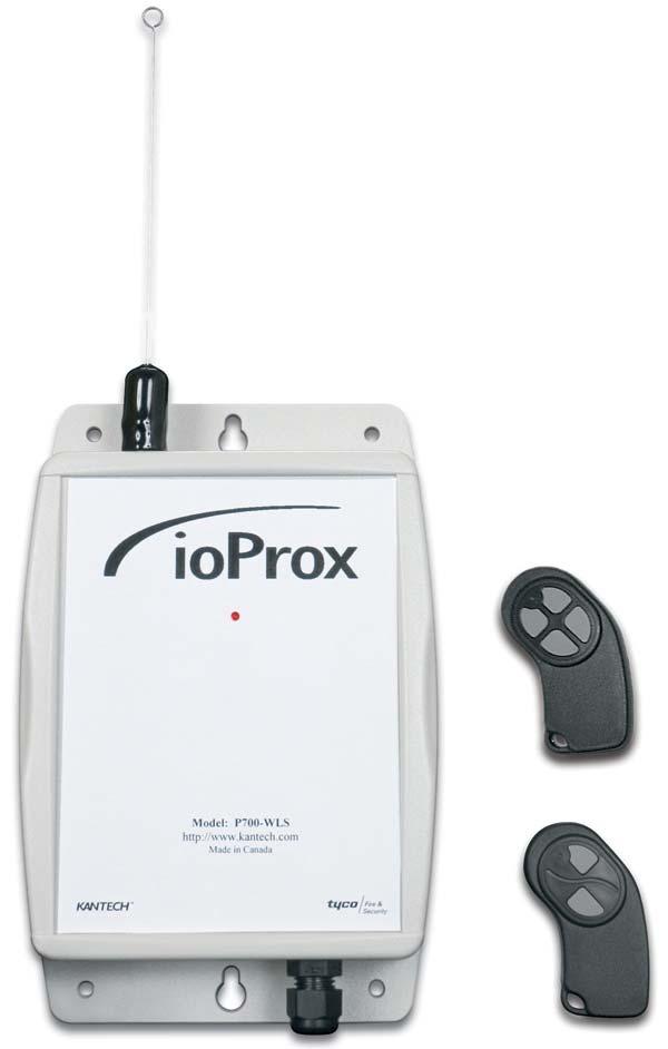
4 System Overview The P700WLS IoProx receiver unit is designed to interface with an access control panel card reader port using the Wiegand protocol or the Kantech extended Secure Format (XSF). The Ioprox receiver can read from a distance of up to m. (150 ft.) with a power dipole antenna or m. (100 ft.) with a standard antenna. Ioprox transmitters come in two versions: with 2 or 4 buttons. And each can come with or without an integrated IoProx key tag. The receiver unit receives the ID credentials from transmitters which consist of a site code and ID number. For increased security, the Ioprox transmitter uses incremental packet transmission so that a different transmission code is created every time the button is pressed, Transmitters with integrated Ioprox key tag also permit access to users when both Ioprox receivers and card readers are installed in different areas of the same building. The receiver jumpers can be configured to determine which button on the key tag transmitter will activate the receiver. The same transmitter can be programmed to operate up to four different receivers (one per button) located within close proximity to each other (and to operate more receivers that are located farther apart.) The transmitter ID will only be sent to the access controller when a valid button is pressed. Inventory The P700WLS Ioprox receiver unit provides a reliable long-range wireless access control from a gate or an overhead door. Each unit is packed with: 1 P-WLS-A1 whip antenna 4 enclosure fastening screws Mounting hardware is not provided. 1
5 Technical Specifications P72WLS/P74WLS Transmitters Power: VDC Power: CR2032 3V lithium battery, included (3 year average lifetime) Current: 50mA (stand-by) 100mA (peak) Operating temperature: 0 C to 70 C (32 F to 158 F) Output: XSF or 26-bit Wiegand selectable Dimensions (HWD) cm: 7.30 x 3.81 x 1.59 Operating temperature: -30 C to 68 C (-22 F to 155 F) Dimensions (HWD) in: 2.88 x 1.50 x 0.63 Dimensions (HWD) cm: x x 4.14 Certification: FCC Dimensions (HWD) in: 7.56 x 5.13 x 1.63 Polycarbonate (HB) with UV stabilizer, weather-resistant, P-WLS-A1 Standard Whip Antenna Enclosure material: IP56, NEMA 4X rated Read range: Up to m. (40 ft.) Frequency: MHz Note: Antenna P-WLS-A1 may be remotely installed using coaxial cable up to 4.5 m. (15 ft.) Cable type: 3 twisted pairs, unshielded cable P-WLS-A2 Power Dipole Antenna Maximum distance from controller at 12 VDC: Certification: 152 m (500 ft) with 18 AWG 112 m (369 ft) with 20 AWG 76 m (248 ft) with 22 AWG FCC Read range: Up to 25 m. (80 ft.) Note: Antenna P-WLS-A2 MUST be installed using coaxial cable up to 4.5 m. (15 ft.), RG1 1/U (Belden ref#8213) coaxial cable is recommended. Optional Note: This equipment has been tested and found to comply with the limits for a Class B digital device, pursuant to part 15 of the FCC Rules. These limits are designed to provide reasonable protection against harmful interference in a residential installation. This equipment generates, uses and can radiate radio frequency energy and, if not installed and used in accordance with the instructions, may cause harmful interference to radio communications. However, there is no guarantee that interference will not occur in a particular installation. If this equipment does cause harmful interference to radio or television reception, which can be determined by turning the equipment off and on, the user is encouraged to try to correct the interference by one of more of the following measures: Reorient or relocate the receiving antenna. Increase the separation between the equipment and receiver. Connect the equipment into an outlet on a circuit different from that to which the receiver is connected. Consult the dealer or an experienced radio/tv technician for help. This device complies with part 15 of the FCC rules. Operation is subject to the following two conditions: This device may not cause harmful interference, and This device must accept any interference received, including interference that may cause undesired operation. 2
6 Installing the Global Coverage When global coverage of a large area is required, there should be a sufficient number of receivers to give overlapping coverage of receiving patterns. Use the SW terminals if the receiver antennas are less than 30.5 m (100 ft) apart. The SW terminal connection prevents data clash at the control panel. (See Figure 2, Note 5 on page 6.) Power Supply and Grounding Power requirements: VDC, 50mA (stand-by), 100mA (peak). A linear type power supply is recommended if a separate power supply is used. Proper grounding gives an electrical charge, like an electrical static discharge or a near lightning strike, a path from which to dissipate its energy safely into the earth. It is strongly recommended to connect an earth ground wire to each receiver unit. (See Figure 2, Note 2 and Note 4 on page 6.) Recommended Wiring Distance at 12 Vdc P700WLS receiver: 3 twisted pairs, unshielded cables With #18 AWG: 152 m (500 ft) With #20 AWG: 112 m (369 ft) With #22 AWG: 76 m (248 ft) 3


7 Data Path Selector Settings The receiver unit provides for field selectable pins JP2 located near the center of the board (Figure 1) Receiver Terminal Block Location The receiver terminal block is removable. (Refer Figure 1) It can be mounted vertically or horizontally. Connect 22 to 14 AWG wires to the blue terminal block. Figure 1 Terminal Block Location 4
8 S1 Receiver Configuration Placing the DIP switches in the ON or OFF position determines which specific button on the multi-button transmitter will activate the receiver and Wiegand format to be transmitted to the control panel. (See Table 1 below) Data Path Selector Settings: Kantech XSF (default): Position 4 (ON). 26-bit Wiegand: Position 4 (OFF). Button 1 Button 3 S1 S The selectors for position 1 and 2 select which of the four buttons will activate the receiver. Button 2 Button 4 S1 S Format Button XSF Button 1 OFF OFF ON ON Button 2 OFF ON ON ON Button 3 ON OFF ON ON Button 4 ON ON ON ON 26W Button 1 OFF OFF ON OFF Button 2 OFF ON ON OFF Button 3 ON OFF ON OFF Button 4 ON ON ON OFF Table 1 Data Path Selector Settings 5

9 Receiver Wiring Diagrams Figure 2 Typical Installation and Two Receivers Connected to One Port Installations 6


10 Testing the Receivers PCB LED Indicators All LEDs are located on the PC board, inside the box. LED Location Figure 3 LEDs Location Y4: Flashes if the transmitter encryption code does not match the receiver configuration, and will not operate the receiver. Check that the transmitters are programmed to operate with this receiver. Y5: Flashes when the transmitter code is valid. Y6: RF activity indicator. The LED will flicker to indicate the receiver has power. If the LED remains on steady, there is a continuous 433 MHz signal that will prevent the unit from operating reliably. Y8: Flashes when the Wiegand information is sent. Y9: Controlled externally by the access control panel. Typically this is controlled by the access control panels LED confirmation output (Brown wire). The Y9 LED is located on the PC board, inside the box. Y10 Power indicator. 7
11 Receiver Relay The receiver relay activates for one second when a valid button on the transmitter triggers the receiver. The relay on the receiver can be used for testing purposes by adding an audible or visual device to confirm the receiver is receiving the signal consistently from the desired location of the transmitters. Receiver Mounting Location Antennas should be mounted as far away from the ceiling or wall as possible a minimum of 10 cm (4 in) is required. For maximum range, mount antennas vertically, as high as possible and in line of sight. The location should offer protection from vandalism. The receiver unit can also be mounted flush with a wall or ceiling if the antenna is remotely connected with a coaxial patch cord and mounted 10 cm. (4 in.) from the wall or ceiling surface. (Refer to Figure 4). Limit the length of the 75-ohm coaxial cable (RG-11/U) to less than 4.5 m. (15 ft.) and use weatherproof F-connectors if mounting the cable outside. Water droplets accumulating inside an F- connector will short out the cable. For best performance, mount the antenna vertically. DO NOT mount receiver and antenna near any source of interference (i.e. proximity card readers, other RF receivers, motors, etc) or metal structures (i.e. pipes). The greater the height and distance between the antenna and the source of interference the better a minimum of 2.4 m (8 ft) is recommended. Installing antennas too close to an electrical source will affect performance. Wall Mounted Ceiling Mounted Ceiling Minumum four (4) inches from wall L-Bracket Wall Receiver Non-metallic material - eg. wood Receiver * L-Brackets are not included Figure 4 Wall and Ceiling Mounted Receivers 8
 second the button you programmed earlier to activate the receiver. A red indicator light will flash for the duration of the transmission.")

12 Testing the Transmitters Operating Instructions The following instructions can be used for both models (2 or 4 buttons) 1. On the key tag transmitter, press for one (1) second the button you programmed earlier to activate the receiver. A red indicator light will flash for the duration of the transmission. Note: Pressing and holding the button down only transmits a short pulse. 2. Release and press the button again to send another transmission. 3. If the light on the transmitter does not light up when you press any of the buttons, replace the battery. Troubleshooting Replacing the Transmitter Battery Tools required: Flat edge tool or screwdriver Battery model CR Before you start, make sure the case is laid flat on the table and upside down. 2. From the key ring corner, use a flat edge tool or screwdriver to carefully pry open the case. 3. Push the coin shaped battery out of its holder and replace it with a similar battery being careful to place the positive (+) side on top. DO NOT install the battery backwards. It will damage the device. 4. Close the case. You will hear a snap that indicates the case is closed. 5. Test the transmitter and observe the red flashing light at the front when pressing a button. 9
P700-WLS ioprox Receiver
 Installation Manual DN1628-1611 Pre-Installation Notes Copyright 2016 Tyco International Ltd. and its Respective Companies. All Rights Reserved. All specifications were current as of publication date and
WLS-5500 Receiver (KSF & W26)
") WLS-5500 Receiver (KSF & W26) Installation Manual DN1869-0912 Warning! This manual contains information on limitations regarding product use and function and information on the limitations as to liability
WLS-5500 Receiver (KSF & W26) Installation Manual DN1869-0912 Warning! This manual contains information on limitations regarding product use and function and information on the limitations as to liability
IMPORTANT: READ AND UNDERSTAND ALL INSTRUCTIONS BEFORE BEGINNING INSTALLATION
 INSTALLATI INSTRUCTIS Model: RB-G-K10 IMPORTANT: READ AND UNDERSTAND ALL INSTRUCTIS BEFORE BEGINNING INSTALLATI The Miller Edge RBand Monitored Gate Edge Transmitter/Receiver system is intended to provide
IMPORTANT: THIS DEVICE MUST BE PROFESSIONALLY INSTALLED READ AND UNDERSTAND ALL INSTRUCTIONS BEFORE BEGINNING INSTALLATION
 INSTALLATI INSTRUCTIS Models: RB-G-K10, RB-TX10 IMPORTANT: THIS DEVICE MUST BE PROFESSIALLY INSTALLED READ AND UNDERSTAND ALL INSTRUCTIS BEFORE BEGINNING INSTALLATI The Miller Edge RBand Monitored Gate
IMPORTANT: THIS DEVICE MUST BE PROFESSIONALLY INSTALLED. READ AND UNDERSTAND ALL INSTRUCTIONS BEFORE BEGINNING INSTALLATION.
 INSTALLATI INSTRUCTIS Model: RB-G-K10 IMPORTANT: THIS DEVICE MUST BE PROFESSIALLY INSTALLED. READ AND UNDERSTAND ALL INSTRUCTIS BEFORE BEGINNING INSTALLATI. The Miller Edge RBand Monitored Gate Edge Transmitter/Receiver
HORNET Remote Control Systems
 HORNET Remote Control Systems Up to 100metres Range 1 3 Button versions 12-30Vdc 0r 230Vac versions Reliable FM Technology Up to four 1000W Relay switches Waterproof Receiver (IP68) Momentary or Latching
Blue Point Engineering Inc.
 Engineering Inc. ireless Radio Control of Puppets Setup Overview RF Control C Pointing the ay to Solutions! Hardware Setup Overview Page 1 Servo No.1 Servo No.2 Control Signal Line RX8ch1,2 Servo Board
CCR24T CCR24R. User s Guide WIRELESS TRANSMITTER SYSTEM WARRANTY SERVICE CARD WARRANTY CARD
 WARRANTY SERVICE CARD WARRANTY CARD PRODUCT NAME Wireless Transceiver System PERIOD MODEL NAME CCR24GEN YEAR PURCHASE DATE.. 200_ From the date of WARRANTY PERIOD.. 200_ purchase. CUSTOMER S ADDRESS :
WPR400 Wireless Portable Reader
 P516-098 WPR400 Wireless Portable Reader User guide Para el idioma español, navegue hacia www.schlage.com/support. Pour la portion française, veuillez consulter le site www.schlage.com/support. Contents
SF C-Series. 900 MHz Wireless Switch Follower/Remote Control Receiver (with On-Board 10-Amp Relays) Typical Applications
 Typical Applications") Long Range Wireless Applications 900 MHz Wireless Switch Follower/Remote Control Receiver (with On-Board 10-Amp Relays) The SF900C Series Remote Control/Switch Followers are a twoway system designed to
Long Range Wireless Applications 900 MHz Wireless Switch Follower/Remote Control Receiver (with On-Board 10-Amp Relays) The SF900C Series Remote Control/Switch Followers are a twoway system designed to
Table of Contents. Mounting Diagram.. Wiring Information.. Setting the STR 1000 as a Repeater or a Transmitter. STR 1000 Frequently Asked Questions..
 STR 1000 Series Repeater Installation Manual (V 3.0) Table of Contents MOUNTING Mounting Diagram.. Page 2 WIRING INFORMATION Wiring Information.. Page 3 Setting the STR 1000 as a Repeater or a Transmitter.
Radio Link Starter Kit
 Radio Link Starter Kit Installation Manual BARTLETT Instrument Co. 1032 Avenue H Fort Madison, IA 52627 319-372-8366 www.bartinst.com Table of Contents Radio Link Starter Kit Manual... 3 System Requirements...
Radio Link Starter Kit
 Radio Link Starter Kit Installation Manual BARTLETT Instrument Co. 1032 Avenue H Fort Madison, IA 52627 319-372-8366 www.bartinst.com Table of Contents Radio Link Starter Kit Manual... 3 System Requirements...
Instruction Manual. for Media Monkey. 1
 TM TM Instruction Manual for Media Monkey www.audioaperemote.com 1 Congratulations on acquiring your fine Audio Ape product Let s dive right in, getting up and running is a snap. Here are the components:
INSTALLATION INSTRUCTIONS FOR THE CLIKCARD COMMERCIAL RECEIVER (NARROW BAND)
") Doc. 6001200 Rev. B INSTALLATION INSTRUCTIONS FOR THE CLIKCARD COMMERCIAL RECEIVER (NARROW BAND) TABLE OF CONTENTS TABLE OF CONTENTS...1 INSTALLATION FOR INFINITY AND PROCARD...3 PULLING CABLE... 3 MOUNTING
Doc. 6001200 Rev. B INSTALLATION INSTRUCTIONS FOR THE CLIKCARD COMMERCIAL RECEIVER (NARROW BAND) TABLE OF CONTENTS TABLE OF CONTENTS...1 INSTALLATION FOR INFINITY AND PROCARD...3 PULLING CABLE... 3 MOUNTING
USER MANUAL Digital Wireless Gateway U9120-W4 (P/N: 44002G-01)
") USER MANUAL Digital Wireless Gateway U9120-W4 (P/N: 44002G-01) 19549P-82 (11-16) 2016 DAVID CLARK COMPANY INCORPORATED Cautions and Warnings READ AND SAVE THESE INSTRUCTIONS. Follow the instructions in
USER MANUAL Digital Wireless Gateway U9120-W4 (P/N: 44002G-01) 19549P-82 (11-16) 2016 DAVID CLARK COMPANY INCORPORATED Cautions and Warnings READ AND SAVE THESE INSTRUCTIONS. Follow the instructions in
Blue Point Engineering
 Overview Blue Point Instruction Board 2-CH Boards, Terminal Block and Ribbon Cable I Type: RF Radio (315 MHz) 1-2 Channels (FCC Part 15 Compliant Components). Operating Voltage: 6-15 VDC @ 1 Amp (Wall
USER MANUAL Universal Gateway U9921-GUV (P/N: 40994G-01)
") USER MANUAL Universal Gateway U9921-GUV (P/N: 40994G-01) 2012 DAVID CLARK COMPANY INCORPORATED Cautions and Warnings READ AND SAVE THESE INSTRUCTIONS. Follow the instructions in this installation manual.
USER MANUAL Universal Gateway U9921-GUV (P/N: 40994G-01) 2012 DAVID CLARK COMPANY INCORPORATED Cautions and Warnings READ AND SAVE THESE INSTRUCTIONS. Follow the instructions in this installation manual.
Blue Point Engineering Inc.
 nc. Wireless Radio Control of Puppets Setup Overview RF Control C Hardware Setup Overview Servo No.1 Servo No.2 Control Signal Line RX8-ch1,2 Servo Board WZ-12 RX8-ch3,4 Servo Board WZ-12 Power Line DC
ANT400 OPTIONAL REMOTE ANTENNA MODULE
 P516-099 ANT400 OPTIONAL REMOTE ANTENNA MODULE INSTRUCTIONS FOR ANT400-REM-I/O, ANT400-REM-I/O+6dB, ANT400-REM-CEILING, ANT400-REM-HALL Para el idioma español, navegue hacia www.schlage.com/support. Pour
RF (RADIO FREQUENCY) WIRELESS PENDANT
 WIRELESS PENDANT") NOTE: The following information is an addition to the Operation section in the lift system owner s manual. It describes the RF wireless pendant for your lift system. You must read the lift system owner
NOTE: The following information is an addition to the Operation section in the lift system owner s manual. It describes the RF wireless pendant for your lift system. You must read the lift system owner
Radio Micro Force Manual v1.1
 Radio Micro Force Manual v1.1 Preston Cinema Systems 1659 Eleventh Street Santa Monica CA 90404 tel 310-453-1852 fax 310-453-5672 www.prestoncinema.com Table of Contents 1. Description 2. Operation 3.
Copyright Black Box Corporation. All rights reserved.
 Copyright 2004. Black Box Corporation. All rights reserved. 1000 Park Drive Lawrence, PA 15055-1018 724-746-5500 Fax 724-746-0746 JULY 2004 LW6200A LW6201A Pure Networking 2.4-GHz Antennas CUSTOMER SUPPORT
S ENSORLINK INSTALLATION MANUAL
 S ENSORLINK INSTALLATION MANUAL The SensorLink Transmitter (#7610) and SensorLink Receiver (#7611) are designed to work with Davis Instruments Weather Monitor II and the Weather Wizard III to enable wireless
System Requirements: D-Link Systems, Inc.
 System Requirements: Minimum System Requirements: CD-ROM Drive Computers with Windows, Macintosh, or Linux-based operating systems Installed Ether net Adapter Internet Explorer version 6.0 or Netscape
Ambient Weather WS-40 Wireless Indoor / Outdoor Thermometer
 Ambient Weather WS-40 Wireless Indoor / Outdoor Thermometer Table of Contents 1. Introduction... 1 2. Getting Started... 1 2.1 Parts List... 1 2.2 Thermometer Sensor Set Up... 1 2.3 Display Console Set
9RCT4334 Four Button. 2 3/4 X 1 3/8 X 9/16 (70mm x 35mm x 14mm) 2 3/4 x 2 1/8 x 1 (70mm x 55mm x 25mm)
 2 3/4 x 2 1/8 x 1 (70mm x 55mm x 25mm)") INSTALLATI 9RCR433/9RCT433 433MHz Transmitters & Receiver Description The 433MHz Series Transmitters and Receiver are ideal for the wireless activation and/or sequencing of automatic doors and remote access
INSTALLATI 9RCR433/9RCT433 433MHz Transmitters & Receiver Description The 433MHz Series Transmitters and Receiver are ideal for the wireless activation and/or sequencing of automatic doors and remote access
Interface Manual Tank Level Float Stick System
 1 Interface Manual Tank Level Float Stick System SignalFire Model: Sentinel-FS-3BIS The SignalFire Sentinel Float Stick Node is an Intrinsically Safe device with the following features: - Standard SignalFire
Ambient Weather F007PF 8-Channel Wireless Water Thermometer User Manual
 Ambient Weather F007PF 8-Channel Wireless Water Thermometer User Manual Table of Contents 1 Introduction... 2 2 Getting Started... 2 Parts List... 2 2.1 Water Thermometer Sensor Set Up... 2 3 Glossary
Ambient Weather F007TP 8-Channel Wireless Probe Thermometer User Manual
 Ambient Weather F007TP 8-Channel Wireless Probe Thermometer User Manual Table of Contents 1 Introduction... 2 2 Getting Started... 2 2.1 Parts List... 2 2.2 Probe Thermometer Sensor Set Up... 2 3 Remote
IS76 Beacon with Ferrite Antenna Installation Manual
 IS76 Beacon with Ferrite Antenna Installation Manual V2 F.01U.278.518 2013.10 Document # F.01U.278.518 V2 IS76 Beacon with Ferrite Antenna: Installation Manual Edition: October 2013 Author: TeleAlarm TeleAlarm
Wireless Outdoor/Indoor Rechargeable Speaker System. User's Manual
 Wireless Outdoor/Indoor Rechargeable Speaker System User's Manual Contents 2 Specifications 3 Product Features 4 Introduction 5 Setting up Setting Up the Transmitter Locating the Transmitter Charging
IRRIGATION 810-3R RECEIVER GUIDE
 IRRIGATION 810-3R RECEIVER GUIDE Pg. 2 HOT SHOT OVERVIEW 3 RECEIVER FUNCTION SWITCH SETTINGS 4 RECEIVER INDICATOR LIGHTS 4 SUPERVISION FEATURE 5 RECEIVER HOOKUP TO ENGINE DRIVEN WELL 6 RECEIVER HOOKUP
XD-V70 Wireless Receiver
 XD-V70 Wireless Receiver Pilot s Handbook Manuel de pilotage Pilotenhandbuch Pilotenhandboek Manual del Piloto 取扱説明書 See www.line6.com/manuals for Advance Guide Advanced Users Guide available @ www.line6.com/manuals
MPRF01 Wireless 5uA Inductive Proximity Sensor RF System
 System Description; The MPRF01 is a simple ready to use Wireless Inductive. No programming is required; just insert 2, (1.5V) AA batteries into the Transmitter module. The RF receiver module is connected
Disclaimers. Important Notice
 Disclaimers Disclaimers Important Notice Copyright SolarEdge Inc. All rights reserved. No part of this document may be reproduced, stored in a retrieval system, or transmitted, in any form or by any means,
Installation and Operation Manual MSI. Multi-Sensor Interface Hub. Interface Module for all Sensors Network and Wireless CAUTION
 Installation and Operation Manual MSI Multi-Sensor Interface Hub Interface Module for all Sensors Network and Wireless CAUTION This equipment complies with the limits for a Class B digital device, pursuant
Quick Start Guide. Antenna Alignment Tool AIMWLLR0-35. QSG rev 7 AIMWLLR0-35 [NRB-0200] QSG.indd 1
![Quick Start Guide. Antenna Alignment Tool AIMWLLR0-35. QSG rev 7 AIMWLLR0-35 [NRB-0200] QSG.indd 1](/thumbs/86/94268876.jpg "Quick Start Guide. Antenna Alignment Tool AIMWLLR0-35. QSG rev 7 AIMWLLR0-35 [NRB-0200] QSG.indd 1") Quick Start Guide Antenna Alignment Tool AIMWLLR0-35 QSG-00097 rev 7 AIMWLLR0-35 [NRB-0200] QSG.indd 1 Welcome This quick start guide is designed to familiarize you with the features and use of the NetComm
Quick Start Guide Antenna Alignment Tool AIMWLLR0-35 QSG-00097 rev 7 AIMWLLR0-35 [NRB-0200] QSG.indd 1 Welcome This quick start guide is designed to familiarize you with the features and use of the NetComm
Table of Contents. Wall Mount Installation Page 2 Double Mount Installation Page 3. Wiring Information... Page 4. Operational Instructions Pages 5-8
 MOUNTING Table of Contents Wall Mount Installation Page 2 Double Mount Installation Page 3 WIRING INFORMATION Wiring Information... Page 4 OPERATION Operational Instructions Pages 5-8 FREQUENTLY ASKED
IS76 Beacon with Ferrite Antenna Installation Manual
 IS76 Beacon with Ferrite Antenna Installation Manual Edition: June 2016 Document N : F.01U.136.807 V3 Page 1 of 10 Document No F.01U.136.807 V3 IS76 Beacon with Ferrite Antenna: Installation Manual Edition:
Transmitter. User Manual. Firmware version 1.0 and greater
 ProRF SPC Transmitter User Manual Firmware version 1.0 and greater FCC NOTICE This equipment has been tested and found to comply with the limits for a class B digital device, pursuant to part 15 of the
Wireless AC Circuit Identifier
 User's Guide Wireless AC Circuit Identifier Models RT30 and RT30-E 99 Washington Street Melrose, MA 02176 Phone 781-665-1400 Toll Free 1-800-517-8431 Visit us at www.testequipmentdepot.com Back to the
Ambient Weather WS-0270 Wireless Indoor / Outdoor Thermometer with Indoor Humidity User Manual
 Ambient Weather WS-0270 Wireless Indoor / Outdoor Thermometer with Indoor Humidity User Manual Table of Contents 1 Introduction... 1 2 Getting Started... 1 2.1 Parts List... 2 2.2 Recommend Tools... 2
OEM KEYFOB TRANSMITTER DATA GUIDE
 CMD-KEYX-XXX OEM KEYFOB TRANSMITTER DATA GUIDE DESCRIPTION The Linx CMD-KEYX-XXX Remote Command keyfob is ideal for generalpurpose remote control and command applications. The unit has been precertified
WIRELESS TEMPERATURE S TATION I NSTALLATION MANUAL
 Wireless Temp Page 1 Thursday, December 7, 2000 2:09 PM WIRELESS TEMPERATURE S TATION I NSTALLATION MANUAL The Wireless Temperature Station is for use with Wireless Vantage Pro TM. COMPONENTS The Wireless
UHF Wireless Transmitter
 UHF Wireless Transmitter Model: EM-100 Diversity Wireless System for On Stage In-ear Monitor Table of Contents System Components...1 Transmitter Features...2 Receiver Features...4 System Setup...5 Specifications...7
PIM400-TD2. User guide for Panel Interface Module PIM400-TD2
 P516-096 PIM400-TD2 User guide for Panel Interface Module PIM400-TD2 Para el idioma español, navegue hacia www.schlage.com/support Pour la portion française, veuillez consulter le site www.schlage.com/support
USER MANUAL. Sens it SENS IT 2.4
 USER MANUAL www.sensit.io Sens it SENS IT 2.4 SUMMARY SAFETY INSTRUCTIONS 4 I. CONTENT OF THE PACK 4 II. PRESENTATION 5 III. HOW TO START 8 IV. TECHNICAL SPECIFICATIONS 9 V. WARNING STATEMENTS 10 VI. CREDITS
Focus Iris Manual Ver 1.1
 Focus Iris Manual Ver 1.1 Preston Cinema Systems 1659 Eleventh Street Santa Monica CA 90404 tel 310 453 1852 fax 310 453 5672 www.prestoncinema.com Table of Contents 1. Description 2. Operation 3. Specifications
Wireless Network Manager (NM) and Wireless Transceiver (TRV)
 and Wireless Transceiver (TRV)") R Installation and Operation Instructions Wireless Network Manager (NM) and Wireless Transceiver (TRV) for PLATINUM CONTROLS With COMMUNICATION The New Heat-Timer Wireless Network Sensor System is designed
R Installation and Operation Instructions Wireless Network Manager (NM) and Wireless Transceiver (TRV) for PLATINUM CONTROLS With COMMUNICATION The New Heat-Timer Wireless Network Sensor System is designed
WPR400 Wireless Portable Reader User guide
 *P516-098* P516-098 WPR400 Wireless Portable Reader User guide Para el idioma español, navegue hacia www.allegion.com/us Pour la portion française, veuillez consulter le site www.allegion.com/us Contents
Doc Rev - B. INSTALLATION AND PROGRAMMING INSTRUCTIONS FOR THE ClikCard NARROW BAND RESIDENTIAL GARAGE DOOR RECEIVER
 Doc - 6001238 Rev - B INSTALLATION AND PROGRAMMING INSTRUCTIONS FOR THE ClikCard NARROW BAND RESIDENTIAL GARAGE DOOR RECEIVER TABLE OF CONTENTS PART 1 INTRODUCTION AND BASICS...1 A. MOUNTING THE RECEIVER
STI REPEATER HOW THE PRODUCT WORKS BEFORE YOU START. Installation and Operation Manual. Model: STI-34109
 Installation and Operation Manual STI REPEATER Model: STI-34109 Thank you for purchasing this fine product. Your satisfaction is very important to us. Please read this manual carefully to get the most
Ambient Weather F007TH Wireless Thermo-Hygrometer User Manual
 Ambient Weather F007TH Wireless Thermo-Hygrometer User Manual Table of Contents 1 Introduction... 2 2 Getting Started... 2 2.1 Parts List... 2 2.2 Thermo-Hygrometer Sensor Set Up... 2 3 Remote Sensor Installation...
RQT-xxx-RCVR Owner s Manual Quick Talk TM Wireless Voice Monitor & Alarm transmitter with factory installed MHz Keyfob Receiver
 RQT-xxx-RCVR Owner s Manual Quick Talk TM Wireless Voice Monitor & Alarm transmitter with factory installed 433.92 MHz Keyfob Receiver RQT-151-RCVR RQT-151M-RCVR RQT-451-RCVR RQT-152-RCVR RQT-152M-RCVR
Keycards come with an imbedded RFID chip and antenna, there is no battery in the keycards. The keycards are encrypted and only
 Index Keycards 02 The following is a description of the type of Keycards and function 03 Programming and Initialization of the RFID Lock 04 Procedure for Initialization 05 Programming- Adding Keycards
PCK43302, PCK MHz Penta series Keyring Remotes with Frequency Hopping
 PCK43302, PCK43304 433MHz Penta series Keyring Remotes with Frequency Hopping FEATURES Small Size keyring remote with 2 or 4 buttons Dual Coding System, dip switch and encrypted code Transmission on 5
SRWF-1022 Series Low Power Wireless Transceiver Module User Manual
 SRWF-1022 Series Low Power Wireless Transceiver Module User Manual Page 1 of 6 I. SRWF-1022 SRWF-1022 User Manual (V1.1) SRWF-1022, the low-power wireless transceiver module is used as the wireless command
STI REPEATER. BEFORE YOU START Refer to this drawing to become familiar with all the parts. Installation and Operation Manual.
 Installation and Operation Manual STI REPEATER Model: STI-34109 Thank you for purchasing this fine product. Your satisfaction is very important to us. Please read this manual carefully to get the most
M508 GPS Tracking Device
 M508 GPS Tracking Device (GPS+GPRS+GSM) Product Manual Edition 1.3 Copyright 10 th Oct., 2009 GATOR GROUP CO.,LTD. All rights reserved. http://www.gatorcn.com China Printing ADD: 312# Ansheng Building,Xixiang
RM24100A. *Maximum transmit power output levels and local radio frequency regulator bodies must be obeyed in the country of operation.
 RM24100A 2.4GHz 100mW RS232 / RS485 / RS422 DSSS Radio Modem (IEEE 802.15.4 compliant) Operating Manual English 1.02 Introduction The RM24100A radio modem acts as a wireless serial cable replacement and
Operating Distance An operating distance (in conjunction with our GLR27 series receivers) of 350 metres is possible.
 of 350 metres is possible.") ELSEMA 27MHz HAND HELD GIGALINK TRANSMITTERS GLT2700, GLT2701, GLT2702, GLT2703, GLT2704 and GLT2708 Features Over 4 billion code combinations Can program any number of transmitters to a receiver High
ELSEMA 27MHz HAND HELD GIGALINK TRANSMITTERS GLT2700, GLT2701, GLT2702, GLT2703, GLT2704 and GLT2708 Features Over 4 billion code combinations Can program any number of transmitters to a receiver High
ELSEMA. GLR2701 Single Channel 27MHz Gigalink Receiver with Timer Controlled Relay Output
 GLR2701 Single Channel 27MHz Gigalink Receiver with Timer Controlled Relay Output ELSEMA Features Wide supply connection 11.0 to 28.0 Volts AC/DC Highly sensitive receiver input stage. When used with GLT27.
INSTALLATION MANUAL FOR SAL SERIES WIRELESS CLOCKS SPECIFICATIONS
 INSTALLATION MANUAL FOR SAL SERIES WIRELESS CLOCKS SPECIFICATIONS Time base: Quartz Power input: Battery (2 D cell) : Part # SAL-1BS-12R-0 95 135 VAC / 60 Hz: Part # SAL-1BS-12R-1 7 28 VAC / 60 Hz: Part
TARGETuner Antenna Management System for Screwdriver Antennas
 TARGETuner Antenna Management System for Screwdriver Antennas www.westmountainradio.com 1020 Spring City Drive Waukesha, WI 53186 262-522-6503 sales@westmountainradio.com 2014, All rights reserved. All
User Manual. ProRF Encoder Transmitter & Receiver
 User Manual ProRF Encoder Transmitter & Receiver WARRANTY Accurate Technology, Inc. warrants the ProScale Systems against defective parts and workmanship for 1 year commencing from the date of original
12V Victor 888 User Manual
 The Victor speed controllers are specifically engineered for robotic applications. The high current capacity, low voltage drop, and peak surge capacity make the Victor ideal for drive systems while its
Innovation First, Inc. RS MHz Robot Controller User Manual
 RS-422 900 MHz Robot Controller User Manual 10.31.2006 www.innovationfirst.com Page 2 Table of Contents 1. Robot Controller Overview... 3 2. Installation... 3 3. Theory of Operation... 3 4. FCC / Industry
INSTALLATION AND OPERATING MANUAL
 INSTALLATION AND OPERATING MANUAL FOR RBDA-PCS-1/25W-90-A INDOOR REPEATER TABLE OF CONTENTS PARAGRAPH PAGE NO BDA OVERVIEW 3 BDA BLOCK DIAGRAM DESCRIPTION 3 FCC INFORMATION FOR USER 3 BDA BLOCK DIAGRAM
Radio receivers type DB317 and DBR1-M4
 Radio receivers type DB317 and DBR1-M4 User manual Art no 006176 Technical data DB317 DBR1-M4 Dimensions (WxHxD) 45x75x21 mm 80x80x50 mm Supply Voltage via control panel 12/24 VAC/VDC Current Consumption
ORiNOCO AP-4000MR-LR and AP-4900MR-LR Access Points Safety and Regulatory Compliance Information
 IMPORTANT! Visit http://support.proxim.com for the latest safety and regulatory compliance information for this product. ORiNOCO AP-4000MR-LR and AP-4900MR-LR Access Points Safety and Regulatory Compliance
AUTOMATE Interior Sun Sensor
 AUTOMATE Interior Sun Sensor 433 MHz Internal sun sensor for automatic shade control. FEATURES: 3 Modes of operation: - Close Mode - Open / Close Mode - Shade Detect Mode 4 Light sensitivity levels INSTR.
Uplink 5500EZ. Installation and User Guide. S e pte m be r 1 2,
 Uplink 5500EZ Installation and User Guide 4 13 464 7 2 S e pte m be r 1 2, 2 01 8 Important Notice Due to the nature of wireless communications, transmission and reception of data can never be guaranteed.
PYRAMID 915MHZ WIRELESS RF TRANSMITTER & REPEATER USER GUIDE. Table of Contents. Overview Installation Setup Specifications...
 Table of Contents Overview................................... 1 Installation.................................. 1 Setup...................................... 2 Specifications..............................
OEM HANDHELD TRANSMITTER DATA GUIDE
 CMD-HHTX-XXX OEM HANDHELD TRANSMITTER DATA GUIDE DESCRIPTION The Linx CMD-HHTX-XXX Remote Command Unit is ideal for generalp u rpose remote control and command applications. The unit has been pre-certified
CRUX II/BTGPS USER GUIDE. Model:D1598
 CRUX II/BTGPS USER GUIDE Model:D1598 0 Federal Communication Commission Interference Statement This equipment has been tested and found to comply with the limits for a Class B digital device, pursuant
FOR TRAINING PURPOSES ONLY DATED MATERIAL. Aperio Hub AH20/AH30 Installation Instructions. ASSA ABLOY, the global leader in door opening solutions
 perio Hub H20/H30 Installation Instructions Covers WL-260 3 May 2011 SS LOY, the global leader in door opening solutions 1 H20/H30 - Table of Contents 2 H20/H30 - FCC and Industry Canada Statements 3 H20/H30
StealthLock is designed to install and program easily and offers: StealthLock is recommended for use on cabinets made from:
 Instruction Manual Thank you for purchasing StealthLock. StealthLock is an innovative solution for keyless invisible security. Using radio frequency technology, StealthLock allows you to secure almost
Door/Window Sensor User Manual HKWL DWS02W
 Door/Window Sensor User Manual HKWL DWS02W 1. PRODUCT OVERVIEW HKWL DWS02W is a Wi Fi wireless Door/Window sensor, you can monitor the status of your door/window in real time through your smart phone.
Wireless 900 MHz Receiver
 Overview and Identification The 900 MHz unit receives a repeated or re-transmitted RF signal from one or more wireless temperature or humidity transmitters. The signal from the transmitter (418 MHz) is
DIGICELL ANYNET NETWORK ACCESS MODULE
 Comm Activity Network Status Service DigiCell Any NET Network Access Module Network Interface Network Service AMPS Cellemetry GSM SMS CDMA GPRS Ethernet 1xRTT RS-232 TCP/IP Input 1 Standard S3 off, S4
On-Line Cardio Theater Wireless Digital Transmitter Installation and Instruction Manual
 On-Line Cardio Theater Wireless Digital Transmitter Installation and Instruction Manual Full installation instructions accompany your Cardio Theater equipment order. This On-Line version of our Installation/Instruction
RM24100D. Introduction. Features. 2.4GHz 100mW RS232 / RS485 / RS422 DSSS Radio Modem (IEEE compliant) Operating Manual English 1.
 Operating Manual English 1.") RM24100D 2.4GHz 100mW RS232 / RS485 / RS422 DSSS Radio Modem (IEEE 802.15.4 compliant) Operating Manual English 1.09 Introduction The RM24100D radio modem acts as a wireless serial cable replacement and
RM24100D 2.4GHz 100mW RS232 / RS485 / RS422 DSSS Radio Modem (IEEE 802.15.4 compliant) Operating Manual English 1.09 Introduction The RM24100D radio modem acts as a wireless serial cable replacement and
Operating Manual LITEMASTER PRO L-478DR-PX L-478DR-A-PX L-478DR-U-PX. Light Meter
 Light Meter Operating Manual LITEMASTER PRO L-478DR-PX L-478DR-A-PX L-478DR-U-PX This manual is specific for Phottix operation. Please read the operating manual and safety precaution carefully to fully
FinishLynx Interface. Includes: Power requirements: 9 VDC Power Adapter (included) Size: Approximately 5 x 3 x 2 Approximate weight: 5.57oz.
 Size: Approximately 5 x 3 x 2 Approximate weight: 5.57oz.") FinishLynx Interface Includes: FinishLynx Wired Interface Or 1 ea. FinishLynx Wireless Interface & MPCX Receiver FinishLynx CAPTION PLATE SET w/layout Diagram Power requirements: 9 VDC Power Adapter (included)
FinishLynx Interface Includes: FinishLynx Wired Interface Or 1 ea. FinishLynx Wireless Interface & MPCX Receiver FinishLynx CAPTION PLATE SET w/layout Diagram Power requirements: 9 VDC Power Adapter (included)
Wireless Transceiver (TRV)
") Installation and Operation Manual Wireless Transceiver (TRV) For Platinum Controls with Communication WARNING This equipment complies with the limits for a Class B digital device, pursuant to Part 15 of
Installation and Operation Manual Wireless Transceiver (TRV) For Platinum Controls with Communication WARNING This equipment complies with the limits for a Class B digital device, pursuant to Part 15 of
802.11n, 2.4G 1T1R Wireless LAN PCI Express Half Mini Card
 802.11n, 2.4G 1T1R Wireless LAN PCI Express Half Mini Card WN6605LH Realtek RTL8191SE User s Manual Ben J. Chen 3/4/2010 Federal Communication Commission Interference Statement This equipment has been
INSTRUCTION MANUAL. IBRit - rf1 - usb PC - Station for wireless Data transmission. M e s s t e c h n i k. Messtechnik GmbH & Co.
 M e s s t e c h n i k INSTRUCTION MANUAL PC - Station for wireless Data transmission Document No. : D1F604 001 Version : April 2006 Copyright : IBR Messtechnik GmbH & Co. KG Contents 1. Introduction 1.1
Installation Instructions RF5910
 Installation Instructions RF5910 HES, Inc. 22630 N. 17th Ave. Phoenix, AZ 85027 800-626-7590 1 Product Description Dimensions Orientation Compatibility Access Control Systems Proximity Cards Frequency
Wireless TFT LCD Monitor
 Wireless TFT LCD Monitor Description Screen Ratio: 16 : 9 Resolution: 800*RGB*480 TV: PAL / NTCS Voltage: 10--28V Rated Capacity: 5W Brightness: 450cd/m2 Contrast: 450:1 Operate temperature: -20~65 Display
Link Mobile Gateway User Guide A ProVIEW System Component
 A ProVIEW System Component Omni-ID office locations: US UK China India Southeast Asia Germany 1. CONTENTS 1. Introduction... 3 About this Document... 3 Related Products... 3 Regulatory Approvals... 4 Certifications...
Driveway Alarm INSTALLATION MANUAL
 WIRELESS ACCESS CONTROLS Driveway Alarm INSTALLATION MANUAL Mounting post Transmitter Receiver Transformer Sensor Kit Includes: Transmitter Module Sensor Receiver Transformer Mounting post (3 pieces) Installation
Point Six Wireless Unique, High Value Wireless Solutions. 418 MHz Transmitter
 Point Six Wireless Unique, High Value Wireless Solutions Point Sensor Temperature/Humidity 418 MHz Transmitter FEATURES Measures Temperature and Relative Humidity Up to 600 foot transmission range Transmission
Schlage Control Smart Locks
 Schlage Control Smart Locks with Engage technology User guide Schlage Control Smart Locks with Engage technology User Guide Contents 3 Warranty 4 Standard Operation 4 Operation from the Inside 4 Operation
ScreenLogic Wireless Connection Kit. Installation Guide. pool/spa control system
 pool/spa control system ScreenLogic Wireless Connection Kit Installation Guide P/N 520663 - Rev A 8 Technical Support Contact Technical Support at: Sanford, North Carolina (8 A.M. to 5 P.M.) Phone: (800)
AD511-2 Active Iridium Antenna User Manual. 1 AD511-2 Active Iridium Antenna User Manual October FEBRUARY 2018 V2.0
 AD511-2 Active Iridium Antenna User Manual 1 AD511-2 Active Iridium Antenna User Manual October 2017 1.0 FEBRUARY 2018 V2.0 TABLE OF CONTENTS 1. FCC APPROVAL... 3 1.1. FCC 15.19 (A) (3)... 3 1.2. FCC 15.105
USB RX Speed. Instructions for use Betriebsanleitung Mode d emploi Instrucciones para el uso Istruzioni per l uso
 USB RX Speed 19348 Instructions for use Betriebsanleitung Mode d emploi Instrucciones para el uso Istruzioni per l uso E L S U S B R X S p e e d M a n u a l 0 2. 0 2. 2 0 1 0 / / 7 3 3 2 4 English 1-8
User Manual. Product Name:tablet Model Name:TM800A740M Brand Name:NuVision. Manufacture:Shenzhen Vastking Electronic Co.,LTD.
 User Manual Product Name:tablet Model Name:TM800A740M Brand Name:NuVision Manufacture:Shenzhen Vastking Electronic Co.,LTD. FCC Warning This device complies with part 15 of the FCC
Kit Kit. GeoSteer GS-900 Radio Kit. GS-900 Radio Kit Installation Instructions Rev A
 200-0652-01 Kit 200-0652-02 Kit GeoSteer GS-900 Radio Kit Item Component Part Number Qty Notes 1. Assembly, Radio GS-900 200-0642-01 (North America) 200-0642-02 (Australia) 1 Radio assembly in kit is region
FSW-1650 FSW User Manual. 16/24-Port 10/100 Rackmount Switch
 FSW-1650 FSW-2450 User Manual 16/24-Port 10/100 Rackmount Switch V1.0.0.0810 COPYRIGHT & TRADEMARKS Specifications are subject to change without notice. LevelOne is a registered trademark of Digital Data