FrankenCIS Microsquirt Manual supplement Reanimotion International Pty Ltd
|
|
|
- Clifford Park
- 5 years ago
- Views:
Transcription


1 FrankenCIS Microsquirt Manual supplement
2 FrankenCIS All rights reserved. No parts of this work may be reproduced in any form or by any means graphic, electronic, or mechanical, including photocopying, recording, taping, or information storage and retrieval systems without the written permission of the publisher. Products that are referred to in this document may be either trademarks and/or registered trademarks of the respective owners. The publisher and the author make no claim to these trademarks. While every precaution has been taken in the preparation of this document, the publisher and the author assume no responsibility for errors or omissions, or for damages resulting from the use of information contained in this document or from the use of programs and source code that may accompany it. no event shall the publisher and the author be liable for any loss of profit or any other commercial damage caused or alleged to have been caused directly or indirectly by this document. Printed: August 2018 Publisher Reanimotion Engineering Pty Ltd Managing Editor Steve
3 Contents I Table of Contents Part I troduction 2 Part II Wiring Spare ADC / Control Pressure Fuel... System CIS Fuel... System CISE 9 Part III System Setup and Tuning 11 1 CIS... with WUR 12 2 CISE Idle... Valve 18 4 Firmware Spartan2... Wideband Setup 20 Part IV Reference stall Parts List dex 24 0
4 Part I
5 troduction 1 2 troduction FrankenCIS is a software and hardware project to allow the MegaSquirt family of engine controllers to replace the Bosch WUR or control the DPR/EHA valve on later systems. its simplest implementation mimicking the WUR by a temperature to bar map and closed loop pressure control. With optional interceptor like + control of fuel mixture using the full mapping abilities of the MegaSquirt family. More advanced implementations the sky is the limit really, Spark and Idle control, Full fuel mapping, Closed loop wideband O2 control, Boost enrichment and or pressure control, and so on. This document should be used in conjunction with the Microsquirt Hardware Manual available from MSExtra.com ( ) How are we doing it? We have created a new firmware or operating system based on the MS2extra code and MegaSquirt hardware which retains all the relevant EFI tuning, spark control and accessory features, but when switched into one of the KJet / CIS modes completely changes the way it interacts with the fuel side of the system. KJetronic basic controls an electronic WUR block by targeting a control pressure map referencing Time/Temperature. MS2Extra firmware has been modified to change a "Squirt per Rev" to mapped fuel pressure control on jector1. The target pressure is taken from a new map representing the WUR basic bar/temp curve and then modified by percentage according to changes in the remaining tuning options. The standard style EFI Load and RPM referenced fuel demand map is them mixed in on top to provide an enhanced version of the manifold pressure adjustment available in the standard mechanical WUR. KJetronic Lambda as above with the addition of a second map table controlling the Frequency Valve or equivalent. in this mode we also split the additional EFI style tuning features between the WUR and FV where appropriate. KEJetronic completely different to the first two, No WUR, No Frequency Valve, static control pressure and complete control of the differential pressure between the top and bottom chambers of the Fuel Distributor. This option requires a small interface module between the DPR (sometimes called EHA) and the MicroSquirt to convert the injector control signals. THIS PRODUCT MAY BE USED SOLELY ON VEHICLES USED IN SANCTIONED COMPETITION WHICH MAY NEVER BE USED UPON A PUBLIC ROAD OR HIGHWAY, UNLESS PERMITTED BY SPECIFIC REGULATORY EXEMPTION (VISIT THE EMISSIONS PAGE AT FOR STATE BY STATE DETAILS. IT IS THE RESPONSIBILITY OF THE INSTALLER AND/OR USER OF THIS PRODUCT TO ENSURE THAT IT IS USED IN COMPLIANCE WITH ALL APPLICABLE LAWS AND REGULATIONS. IF THIS PRODUCT WAS PURCHASED IN ERROR, DO NOT INSTALL AND/OR USE IT. THE PURCHASER MUST ARRANGE
6 3 FrankenCIS TO RETURN THE PRODUCT(S) FOR A FULL REFUND. THIS POLICY ONLY APPLIES TO INSTALLERS AND/OR USERS WHO ARE LOCATED IN THE UNITED STATES, HOWEVER CUSTOMERS WHO RESIDE IN OTHER COUNTRIES SHOULD ACT IN ACCORDANCE WITH THEIR LOCAL LAWS AND REGULATIONS. WARNING: This installation is not for the tuning novice! Use this system with EXTREME caution! FrankenCIS allows for total flexibility in engine tuning. Misuse or improper tuning of this product can destroy your engine! If you are not well versed in engine dynamics and the tuning of engine management systems DO NOT attempt the installation. Refer the installation to an FrankenCIStrained tuning shop or call for technical assistance. NOTE: All supplied FrankenCIS calibrations, Wizards and other tuning information are offered as potential starting points only. IT IS THE RESPONSIBILITY OF THE ENGINE TUNER TO ULTIMATELY CONFIRM IF THE CALIBRATION IS SAFE FOR ITS INTENDED USE. FrankenCIS holds no responsibility for any engine damage that results from the misuse or mistuning of this product!
7 Part II

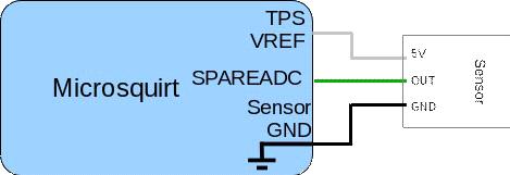
8 5 2 FrankenCIS Wiring General system wiring overview above. dividual installations may vary. Fuelling and Spare ADC connections to the control pressure sensor will depend on the version of CIS and FrankenCIS components installed. The throttle position sensor can be ignored or added if required for CIS and would normally be connected to the Air Plate Potentiometer in CISE installations. Spark and Idle control outputs are optional etc. Pin# Name Color /Out Function Max current 1 +12V Red Main power feed < 1A 2 CANH Blue/Yellow Comms CAN communications 3 CANL Blue/Red Comms CAN communications 4 VR2+ VR2 'Cam' tach in 5 SPAREADC2 (MAF) Pink/Black Spare analogue input 6 FLEX Purple/White Flex / spare input 7 FIDLE Green Out Idle valve output 3A 8 FP (pump) Purple Out Fuel pump relay output 3A
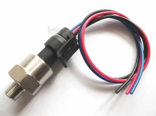
9 Wiring FUEL A Thick Green Out FrankenCIS or DPR 5 5A 10 FUEL B Thick Blue Out 11 SPK B (IGN2) Thick White/Red Out Frequency Valve or DPR 5A 2 Spark B logic output 0.02A 12 SPK A (IGN 1) Thick White Out Spark A logic output 0.02A 13 RX Comms RS232 communications 14 TX Comms RS232 communications 15 BOOT LOAD Purple/Black Bootloader enable input 16 ALED Yellow/Black Out Spare relay output 3A 17 WLED Yellow/White Out Spare relay output 3A 18 Sensor Ground GND Not installed 19 Serial Ground GND Serial Ground 20 Sensor Ground White/Black GND Sensor Ground 21 VR2 VR2 'Cam' tach in 22 POWER GROUND Thick Black GND POWER GROUND 23 POWER GROUND Thick Black GND POWER GROUND 24 MAP Green/Red MAP sensor input 25 CLT Yellow CLT sensor input 26 MAT Orange MAT sensor input 27 TPS Blue TP Sensor input 28 TPS VREF (5V) Gray Out 5V supply for TPS 0.1A 29 CONTROL PRESSURE Orange/Green Control Pressure Sensor 30 OPTO+ Grey/Red Coil negative tach in 31 OPTO Grey/Black Coil negative tach in 32 VR1+ VR1 'Crank' tach in 33 VR1 VR1 'Crank' tach in 34 O2 Pink 35 TACHO Green/Yellow Out Oxygen/lambda sensor in Tacho / rev counter out 0.3A Spare ADC / Control Pressure Spare ADC is Pin 29 Orange / Green on the MicroSquirt The SPAREADC input is used for Control Pressure Measurement for CIS installations and can also be utilized as a lower chamber pressure monitor in CISE installs Fitted either in line or directly to the FrankenCIS metering block, the fuel pressure sensor in the control pressure circuit provides actual Control Pressure in kpa and is used in the Target Pressure feedback loop calculations within the MicroSquirt.

10 7 FrankenCIS


11 Wiring Fuel System CIS FrankenCIS replaces the Bosch Warm Up Regulator at 5, and optionally controls the Frequency Valve at 11


12 9 2.3 FrankenCIS 4 Fuel System CISE Please note: the pin numbers on the Bosch DPR/EHA harness plug for Mercedes vehicles are wrong. Make sure you confirm your wiring by verifying the numbers on the actual DPR/EHA as shown
13 Part III

14 11 3 FrankenCIS System Setup and Tuning After loading the project and connecting to the microsquirt as per the main manual, the screen should look similar to the following Under Engine and Sequential settings, the jector Port Type must be set to correctly match the FrankenCIS system installed, and the number of cylinders should match the target motor. The remaining settings should reflect the installation configuration with a couple of exceptions Squirts per engine cycle is now irrelevant but should be left at 2 or 'constant' if available jector size is also no longer a real value but should be close to the estimated fuel flow per injector if known otherwise 252 is a good number If doing an install with the FrankenCIS ewur then refer to the CIS with WUR section If doing an install with the FrankenCIS DPR terface then refer to the CISE section Throughout the system click or mouse over the blue question mark for an explanation of the setting

15 System Setup and Tuning 3.1 CIS with WUR jector Dead Time PWM contains some FrankenCIS specific settings for range and resolution 12

16 13 FrankenCIS The starting point for the settings above can be adjusted to suit your installation The kpa to VE factor. how m any kpa to 1 point (0.1%) of VE. The system converts a desired VE change to target kpa change using this m ultiplier VE tables are the main point of adjustment for the running fuel trim and should begin as a flat 100 across all cells
17 System Setup and Tuning 14 If set to the Lambda version and j2 is properly connected the the factory Frequency Valve then a second VE table is available by turning on Dual Table Use in General Settings This gives individual control of both systems VE Table 1 has control of the ewur and a mid point of 100 in the table VE Table 2 has control of the Frequency Valve and by default with Freq valve to VE(%) set to 1.0 ranges between 0200 with 100 being the unadjusted mid point in the cells and 50% duty at the valve optionally with Freq valve to VE(%) set to 2.0 ranges between 0100 with 50 being the unadjusted mid point in the cells Basically the frequency valve has a range of Zero to 100% and normal operation is at 50% with lower being lean and higher being rich With our standard table setup we have a value of 100 in the cells as normal so 101 to 200 tunes a richer mixture and below 100 leans it out This is with "Freq valve Duty to VE%" set to 1.0 or a 1:1 ratio as we are actually controlling the valve in half percent steps

18 15 FrankenCIS If we change the setting to 2.0 it then means the table values are directly proportional to the Frequency Valve values so Zero is off, 100 is fully open and 50 = 50% or half way this is now in 1% steps so we lose a bit of resolution, but someone may prefer this option The recommendation is to have it at 1.0 so Table 1 which controls the WUR and Table 2 which controls the Frequency valve are both operating the same with 100 as the center or normal fuel delivery. don't forget to calibrate the Control Pressure sensor via the tools menu

19 System Setup and Tuning 3.2 CISE 16

20 17 FrankenCIS The starting point for the settings above can be adjusted to suit your installation The Duty to VE factor. PWM duty cycle to 1 point (0.1%) of VE. The system converts a desired VE table and EGO change to target PWM Duty change using this m ultiplier VE tables are the main point of adjustment for the running fuel trim and should begin as a flat 100 across all cells

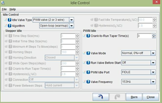
21 System Setup and Tuning 18 The CISE systems have two main variants and the center point or tuning offset for the DPR/EHA varies depending on the system. the early KE generally has a light grey DPR or EHA valve and is usually set to operate positive duty cycle bias requiring a current of around 20ma at idle which might be 120 or so in the map depending on the ration chosen in the settings. the later KE3 or KEMotronic is usually a black DPR/EHA and is usually happy with a centre point of 06ma which would be 100 in the maps This gives individual control of both systems, but means startup values will vary by install depending on the system in place and whether or not the DPR has been previously adjusted manually via the little trim screw If you chose either type of DPR can be manually adjusted to provide a slightly positive bias around 100 in the maps so an electrical control failure will provide the same "Limp Home" capabilities as the late CISE 3.3 Idle Valve The factory rotary Idle valve seems to be happy with the following settings make sure it is fitted with the flyback diode as mentioned in the main manual 1n4001 as recommended
22 19 FrankenCIS

23 System Setup and Tuning Firmware When updating firmware the following dialog will show on connection to the system Select Update ECU Definition, it w ill then allow you to brow se and select the appropriate.ini file for your ECU e.g. m icrosquirt.ini 3.5 Spartan2 Wideband Setup stall and wire up spartan 2 according to the user manual Tuner Studio, tools>calibrate AFR Table>EGO Sensor select "Custom Linear WB", enter the values shown in the picture below and write changes to MegaSquirt.


24 21 FrankenCIS Later on we will change the Custom Linear WB settings to account for offset and linear errors. During powerup Spartan 2's Output Squencer will be triggered, the output sequencer will output 2 distinct calibration voltages on the Linear Output, volts for the first 5 seconds then volts the next 5 seconds, after 10 seconds has passed then the Linear Output will function normally. When a wideband controller is first powered up, it will take about 30 seconds to 1 minute for the Wideband Oxygen Sensor to heat up, while the sensor is heating up the Wideband sensor is unable to read the AFR of the exhaust gas composition, only when the sensor is heated up will the AFR of the exhaust gas composition be correct. Spartan 2's Output sequencer takes advantage of this heatup time when the AFR data is not correct to output calibration voltages that we will use to generate new Tuner Studio settings to compensate for offset and linear errors. While Tuner Studio is running and is actively displaying AFR data, cycle power to Spartan 2 and write down the 2 AFRs shown by tuner studio during the first 5 seconds and then during the next 510 seconds. For this example lets use 13 AFR and 17.1 AFR. Now if there were no offset or iinear errors present the first 5 seconds AFR should be AFR and the 510 seconds AFR should be AFR. Now download and open this Microsoft excel worksheet here Assuming that the first 5 seconds AFR shown by Tuner Studio is 13 AFR and the 510 seconds AFR shown by tuner studio is 17.1 AFR, you would enter 13 and 17.1 into the excel worksheet like the above picture, of course instead of 13 AFR and 17.1 AFR you would enter the AFR shown by your Tuner studio. Once those two AFRs are entered, the settings in the green box will be calculated to compensate for offset and linear errors, this calculated setting you will enter into Tuner

25 System Setup and Tuning 22 Studio and you MegaSquirt will be able to read AFRs from Spartan 2 with an accuracy of 1/10th of an AFR. Tuner Studio, tools>calibrate AFR Table>EGO Sensor select "Custom Linear WB", enter the values shown in green excel worksheet and write changes to MegaSquirt. my example where the frist 5 seconds AFR is 13 AFR and the 510 AFR is 17.1 AFR, my calculated new tuner studio settings is volts and volts. Now if everything was done correctly then now your Megasquirt will be able to read AFR with 1/10th AFR accuracy. Cycle power to Spartan 2 again and now the first 5 seconds AFR should be between / 0.1 AFR and the 510 seconds AFR should be 16.7 AFR +/ 0.1 AFR. Because Megasquirt uses only up to the first decimal place to represent AFR, the best you can do is +/ 0.1 AFR accuracy. **** IMPORTANT **** Once setup and before any tuning is performed it is mandatory that the results of the sensor are verified against a known reference The Dyno AFR sensor should be sufficient
26 Part IV
27 Reference stall Parts List 4 24 Reference stall Parts List MicroSquirt (tm) FrankenCIS (tm) Metering Block #1 or #2 jector Delphi FJ10409 Fuel jector (Single) For Dodge Chrysler Eagle Control Pressure sensor 100psi Digital 1/8NPT Pressure Damper if using FrankenCIS #2 Toyota Gasket for above damper Toyota MAP sensor Denso IAT sensor BOSCH , PORSCHE , VW Engine Temp sensor Bosch WBo2 novate LC2 or 14point7 Spartan (to suit a particular application the last four sensors above can be substituted with anything compatible with MegaSquirt)
28 Back Cover
Syvecs Limited. Syvecs
 Syvecs Limited Syvecs S6 I Pinouts and Wiring Info Support Team 03 02 2014 This document intended for use by a technical audience and describes a number of procedures that are potentially hazardous. Installations
Syvecs Limited. Syvecs S6Plus. Syvecs
 Syvecs Limited Syvecs S6Plus Pinouts and Wiring Info Support Team 03 02 2014 This document intended for use by a technical audience and describes a number of procedures that are potentially hazardous.
Syvecs Limited. Syvecs
 Syvecs Limited Syvecs S8 Pinouts and Wiring Info Support Team 03 02 2014 This document intended for use by a technical audience and describes a number of procedures that are potentially hazardous. Installations
This product is intended for off-road use. TurboTweak cannot be held responsible for any damage resulting from the use of this product.
 Custom Chip for Turbo Buick / Turbo TA Please read before installing! 1. Before installing the chip, disconnect the power to the ECM by unplugging the orange wire with the black connector by the battery.
MobileCollect RF Channel Sniffer Program
 All rights reserved. No parts of this work may be reproduced in any form or by any means - graphic, electronic, or mechanical, including photocopying, recording, taping, or information storage and retrieval
SSI-4 PLUS User Manual
 SSI-4 PLUS User Manual 1 SSI-4 PLUS... 2 1.1 Getting to Know the SSI-4 PLUS... 2 1.2 Channel Functions... 3 2 Wiring and Setup... 3 2.1 Powering the SSI-4 PLUS... 3 2.2 5V for External Sensors... 4 2.3
Test Bench Timing V3.1
 Test Bench Timing V3.1 Purpose:...1 Suggested Test Procedure:...1 Pre Run Setup:...1 Input Control:...1 Left Panel:...1 Setup and Outputs:...1 Channel Parameters:...1 Sensor:...1 Digital Graph:...1 Signal
Bmw E46 M3 Plug in Kit
 Bmw E46 M3 Plug in Kit Installation 1.) Remove the Negative Terminal from the battery on the Vehicle 2.) Remove the DME/Fuse Box cover found in the engine bay as shown below in red 3.) You will then find
EM80. Advanced engine management system with 8 coil drivers, gearshift control and high speed logging. Specifications.
 EM80 Advanced engine management system with 8 coil drivers, gearshift control and high speed logging Specifications Parameter Operating Voltage Power Consumption Value 4V - 35 Volts 250mA Outputs 8 Ignition
Automotive Sensor Simulator. Automotive sensor simulator. Operating manual. AutoSim
 Automotive sensor simulator Operating manual AutoSim Contents Introduction.. page 3 Technical specifications.... page 4 Typical application of AutoSim simulator..... page 4 Device appearance... page 5
Emtron CAN Predefined Dataset 1
 Emtron CAN Predefined Dataset 1 August 2014 Table of Contents 1.0 Parameter Scaling... 3 2.0 Predefined Dataset 1 Transmit Packets... 6 2.1. Predefined Packet 1... 6 2 1.0 Parameter Scaling ALL data/parameters
Document No. 29E P Rev: 1aE
 The MQ12Di is a high-performance engine management system. Its two microprocessors, one dedicated to engine control and the other to data collection, and three Field Programmable Gate Arrays (FPGAs) provide
OVEN INDUSTRIES, INC. Model 5C7-362
 OVEN INDUSTRIES, INC. OPERATING MANUAL Model 5C7-362 THERMOELECTRIC MODULE TEMPERATURE CONTROLLER TABLE OF CONTENTS Features... 1 Description... 2 Block Diagram... 3 RS232 Communications Connections...
6 Repton Close Basildon Essex SS13 1LE United Kingdom +44 (0)
") 6 Repton Close Basildon Essex SS13 1LE United Kingdom +44 (0) 1268 904124 info@liferacing.com www.liferacing.com The F88GDi4 ECU sets the benchmark for integrated direct injection engine management. Based
6 Repton Close Basildon Essex SS13 1LE United Kingdom +44 (0) 1268 904124 info@liferacing.com www.liferacing.com The F88GDi4 ECU sets the benchmark for integrated direct injection engine management. Based
kdfi V1.4 R03 (As from: 24 July. 2013)
") kdfi V1.4 R03 (As from: 24 July. 2013) User Manual (English) You will find the latest information, documentation and CD images on www.k-data.org 1 of 12 Index 1. INTRODUCTION 2. INCLUDED IN DELIVERY 3.
kdfi V1.4 R03 (As from: 24 July. 2013) User Manual (English) You will find the latest information, documentation and CD images on www.k-data.org 1 of 12 Index 1. INTRODUCTION 2. INCLUDED IN DELIVERY 3.
DigiSpeed-GX DC-03. Isolated Control Voltage Generator User s Guide. DigiSpeed-GX PCB Ver:2.0 Firmware Ver: 1.0 Mach3 Ver: 1.84
 DigiSpeed-GX - Users Guide Page 1 Updated: 15. January 2009 DigiSpeed-GX DC-03 Isolated Control Voltage Generator User s Guide DigiSpeed-GX PCB Ver:2.0 Firmware Ver: 1.0 Mach3 Ver: 1.84 DigiSpeed-GX -
MBE - Fault Codes for EPA98 engines (non-egr)
") MBE - Fault Codes for EPA98 engines (non-egr) Text SPN PID/ text Grid Heater 45 PID 45 3 Open 14 Special Instructions. What fault condition triggers this fault? 12 Grid Heater defect Vehicle Speed Sensor
MBE - Fault Codes for EPA98 engines (non-egr) Text SPN PID/ text Grid Heater 45 PID 45 3 Open 14 Special Instructions. What fault condition triggers this fault? 12 Grid Heater defect Vehicle Speed Sensor
DigiSpeed DC-03. Isolated Control Voltage Generator User s Guide. PCB: DC-03 V3.0 Firmware: Ver: 3.0 Mach3: Ver: 1.84
 DigiSpeed DC-03 - Users Guide Page 1 Updated: 29. April 2009 DigiSpeed DC-03 Isolated Control Voltage Generator User s Guide PCB: DC-03 V3.0 Firmware: Ver: 3.0 Mach3: Ver: 1.84 DigiSpeed DC-03 - Users
maxon document number:
 maxon document number: 791272-04 1 Table of contents... 2 2 Table of figures... 3 3 Introduction... 4 4 How to use this guide... 4 5 Safety Instructions... 5 6 Performance Data... 6 6.1 Motor data... 6
TF Electronics Throttle Controller
 TF Electronics Throttle Controller Software Installation: Double click on TFEsetup.exe file to start installation. After installation there will be a shortcut on your desktop. Connecting the USB cable
Instruction Manual. gizzmo. Real Performance Product By GIZZMO
 Real Performance Product By GIZZMO Thank you for purchasing the Gizzmo IBC-R RPM dependent Boost Controller Boost Controller. This manual contains operating instructions and installation procedures that
UNIVERSAL GAUGE P/N BLACK UNIVERSAL GAUGE P/N CHROME UNIVERSAL GAUGE
 UNIVERSAL GAUGE P/N 553-100 BLACK UNIVERSAL GAUGE P/N 553-101 CHROME UNIVERSAL GAUGE These are 2 1/16 diameter gauges designed specifically for use with the Avenger, HP and Dominator EFI systems. They
QuickBuilder PID Reference
 QuickBuilder PID Reference Doc. No. 951-530031-006 2010 Control Technology Corp. 25 South Street Hopkinton, MA 01748 Phone: 508.435.9595 Fax: 508.435.2373 Thursday, March 18, 2010 2 QuickBuilder PID Reference
MFJ ENTERPRISES, INC.
 TM Model MFJ-1924 INSTRUCTION MANUAL CAUTION: Read All Instructions Before Operating Equipment! MFJ ENTERPRISES, INC. 300 Industrial Park Road Starkville, MS 39759 USA Tel: 662-323-5869 Fax: 662-323-6551
MAX11300PMB1 Peripheral Module and Munich (USB2PMB1) Adapter Board Quick Start Guide
 Adapter Board Quick Start Guide") MAX11300PMB1 Peripheral Module and Munich (USB2PMB1) Adapter Board Quick Start Guide Rev 0; 7/14 For pricing, delivery, and ordering information, please contact Maxim Direct at 1-888-629-4642, or visit
MAX11300PMB1 Peripheral Module and Munich (USB2PMB1) Adapter Board Quick Start Guide Rev 0; 7/14 For pricing, delivery, and ordering information, please contact Maxim Direct at 1-888-629-4642, or visit
Contents. Overview Introduction...3 Capabilities...3 Operating Instructions Installation...4 Settings... 5
 User s Manual Contents Overview................................................................. 3 Introduction..............................................................3 Capabilities...............................................................3
O 2 SENSORS Zirconium Dioxide (ZrO 2 ) Software & Hardware Design Guide
 Software & Hardware Design Guide") O 2 SENSORS Zirconium Dioxide (ZrO 2 ) Software & Hardware Design Guide This document describes the recommended software and hardware requirements to control and analyse data from SST Sensing s range of
O 2 SENSORS Zirconium Dioxide (ZrO 2 ) Software & Hardware Design Guide This document describes the recommended software and hardware requirements to control and analyse data from SST Sensing s range of
66 Dodge Charger (and others) Tach board
 Tach board") 66 Dodge Charger (and others) Tach board Introduction: This board replaces the original tachometer driver board in the 66 charger and other cars that use electronics external to the tachometer. The board
66 Dodge Charger (and others) Tach board Introduction: This board replaces the original tachometer driver board in the 66 charger and other cars that use electronics external to the tachometer. The board
Series SPPM2 Graphical User Interface Panel Meter. Specifications - Installation and Operating Instructions MINI USB PORT
 Series SPPM Graphical User Interface Panel Meter Bulletin PCSPPM Specifications Installation and Operating Instructions / [9.0] 9/ [9.] / [9.9] / [.9] / [.] 9/ [9.] JTAG [FOR INTERNAL USE] ALARMS, SERIAL
Vehicle Data Display and Logger Installation and Operation Manual Rev Focus Applied Technologies
 Vehicle Data Display and Logger Installation and Operation Manual Rev 1. 1-215 Focus Applied Technologies INTRODUCTION This Vehicle Data Display and Logger is designed as a robust display and logger for
EMS EM-Tech Race Dash Manual Version 3.1
 EMS EM-Tech Race Dash Manual Version 3.1 Thank you for purchasing an EMS Race Dash. EMS Computers Pty Ltd Unit 9 / 171 Power St Glendenning NSW 2761 Australia Ph: +612 9675 1414 Email: support@fuel-injection.com
Using Motec Hundred Series ECU s with AEM CD-7 Displays. M400, M600, M800, M880 Transmitting Data Set #1
 Revision Date Initial Release Feb 10, 2017 Using Motec Hundred Series ECU s with AEM CD-7 Displays Supported Motec Hardware M400, M600, M800, M880 Transmitting Data Set #1 M84, M400, M600, M800, M880 Transmitting
Electronically Commutated (EC) Motor Control with Solo, Select and Sync PWM Boards
 Motor Control with Solo, Select and Sync PWM Boards") Electronically Commutated (EC) Motor Control with Solo, Select and Sync PWM Boards The Solo, Select and Sync PWM boards provide a pulse-width modulated (PWM) signal to the EC motor to control fan speed.
Electronically Commutated (EC) Motor Control with Solo, Select and Sync PWM Boards The Solo, Select and Sync PWM boards provide a pulse-width modulated (PWM) signal to the EC motor to control fan speed.
MTY (81)
") This manual describes the option "d" of the SMT-BD1 amplifier: Master/slave electronic gearing. The general information about the digital amplifier commissioning are described in the standard SMT-BD1 manual.
This manual describes the option "d" of the SMT-BD1 amplifier: Master/slave electronic gearing. The general information about the digital amplifier commissioning are described in the standard SMT-BD1 manual.
INDEX. i 1. B Braking Resistor Dimensions: A 24 Braking Resistors: A 20 Braking Units: A 20. DURAPULSE AC Drive User Manual
 INDEX A AC Drive Cover: 1 6 Dimensions: 2 4 External Parts and Labels: 1 6 Heat Sink Fins: 1 6 Input Mode Switch (Sink/Source): 1 6 Introduction to DuraPulse GS3 AC drive: 1 3 Keypad: 1 6 Model Number
Smith Meter AccuLoad III VLR Simulator for AccuLoad III. Installation / Operation Manual. Bulletin MN06116 Issue/Rev 0.3 (10/13)
") Smith Meter AccuLoad III VLR Simulator for AccuLoad III Installation / Operation Manual Bulletin MN06116 Issue/Rev 0.3 (10/13) Caution The default or operating values used in this manual and in the program
Smith Meter AccuLoad III VLR Simulator for AccuLoad III Installation / Operation Manual Bulletin MN06116 Issue/Rev 0.3 (10/13) Caution The default or operating values used in this manual and in the program
MFJ ENTERPRISES, INC.
 Screwdriver Antenna Controller Model MFJ-1926 INSTRUCTION MANUAL CAUTION: Read All Instructions Before Operating Equipment! MFJ ENTERPRISES, INC. 300 Industrial Park Road Starkville, MS 39759 USA Tel:
DigiSpeed-SL DC-04. Isolated Control Voltage Generator User s Guide. DigiSpeed PCB Ver:1.0 Firmware Ver: 1.0 Mach3 Ver: Updated: 5.
 DigiSpeed-SL - Users Guide Page 1 Updated: 5. June 2008 DigiSpeed-SL DC-04 Isolated Control Voltage Generator User s Guide DigiSpeed PCB Ver:1.0 Firmware Ver: 1.0 Mach3 Ver: 1.84 DigiSpeed-SL - Users Guide
The Perception. Is Reality. Test Bench
 Test Bench The Perception Y ou would be hard-pressed to find an automotive technician who has not used an oscilloscope to diagnose a particular problem. Most technicians either own a scope or are planning
Series 70 Servo NXT - Modulating Controller Installation, Operation and Maintenance Manual
 THE HIGH PERFORMANCE COMPANY Series 70 Hold 1 sec. Hold 1 sec. FOR MORE INFORMATION ON THIS PRODUCT AND OTHER BRAY PRODUCTS PLEASE VISIT OUR WEBSITE www.bray.com Table of Contents 1. Definition of Terms.........................................2
Programmable Launch Boost Controller PN 7562
 Programmable Launch Boost Controller PN 7562 Parts Included In This Kit 1 - Controller 4 - Mounting Screws 1 - Wiring Harness 1 - Solenoid Valve Assembly, ASY25190 Parts Required but Not Supplied: 1 -
LCC-10 Product manual
 LCC-10 Product manual Rev 1.0 Jan 2011 LCC-10 Product manual Copyright and trademarks Copyright 2010 INGENIA-CAT, S.L. / SMAC Corporation Scope This document applies to i116 motion controller in its hardware
MSD Programmable PWM Water Control Switch, PN 42592
 MSD Programmable PWM Water Control Switch, PN 42592 IMPORTANT: Read these instructions completely before attempting this installation! WARNING: During installation, disconnect the battery cables. When
Powerful RISC CPU for advanced strategy execution Custom synchronous FPGA processor for engine position tracking up to 25,000 rpm
 F90F ECU The F90F ECU caters for advanced and challenging applications. The twin processor unit uses a high speed RISC processor for code execution and an additional large FPGA for high speed engine position
TECHNICAL DATASHEET #TDAX A DC MOTOR CONTROLLER P/N: AX Variable Speed Control, Onboard I/O CAN SAE J1939, Rugged Packaging
 TECHNICAL DATASHEET #TDAX102000 35A DC MOTOR CONTROLLER P/N: AX102000 Variable Speed Control, Onboard I/O CAN SAE J1939, Rugged Packaging with Electronic Assistant Features: Unidirectional or bi-directional
CCE Image may differ from the actual product By Martin Labbé, eng., Jasmin Goupil & Louis Perreault
 CCE-32 1.09 Image may differ from the actual product By Martin Labbé, eng., Jasmin Goupil & Louis Perreault Index 1. General description... 5 2. Applications... 5 3. Installation... 5 4. Connections...
Fuse, external A 6A, medium time lag. Power consumption W min 20 - max 60 (see paragraph 5.2) Output current A maximum 4.5 (see paragraph 5.
 Output current A maximum 4.5 (see paragraph 5.") 89 251/217 ED EDM-M* DIGITAL AMPLIFIER FOR OPEN LOOP PROPORTIONAL VALVES EDM-M1 single solenoid EDM-M2 double solenoid EDM-M3 two single solenoids independent channels RAIL MOUNTING TYPE: DIN EN 50022
89 251/217 ED EDM-M* DIGITAL AMPLIFIER FOR OPEN LOOP PROPORTIONAL VALVES EDM-M1 single solenoid EDM-M2 double solenoid EDM-M3 two single solenoids independent channels RAIL MOUNTING TYPE: DIN EN 50022
with Electronic Assistant
 TECHNICAL DATASHEET #TDAX021300 Valve Controller 6 On/Off P/N: AX021300 2 Analog and 3 Frequency Command Inputs 6 On/Off Outputs (Option: PWM) CAN (SAE J1939) with Electronic Assistant Features: 2 user
HAU Series Controllers
 Instruction, Installation and Operation Guide for: HAU Series Controllers Document Number: 021-00140 Document Revision: B.2 Document Issue Date: Document Creator: G.Gotting Document Creation Date: 4/21/2011
Pic-Convert Board Instructions
 Pic-Convert Board Instructions This is the fifth version of the Pic-Convert board and now has fully isolated inputs and provides a power supply to make the solution completely industrial. This DAC+PWM
TM5. Guide Book. Hardware Version: 2.00 Software Version: 1.62
 TM5 Guide Book Hardware Version: 2.00 Software Version: 1.62 ii Release Date : 2017-07-10 The information contained herein is the property of Techman Robot Corporation (hereinafter referred to as the Corporation).
ONE SHOT, ONE KILL TAKING AIM AT ADDITIONAL POWER TUNING WITH SNIPER TUNING SOFTWARE FORD BUILDER 59
 FB_0704_Sniper Engine Tune 3/30/07 5:21 PM Page 59 ONE SHOT, ONE KILL TAKING AIM AT ADDITIONAL POWER TUNING WITH SNIPER TUNING SOFTWARE THE HISTORY OF SNIPER TUNING IS AN INTERESTING ONE. PATRICK AND CHRIS
The CO2 Sensor Calibration Kit
 The CO2 Sensor Kit For use with all BAPI CO 2 Sensors Instruction Manual CO 2 Kit Product Identification and Overview BAPI s CO 2 Sensor Kit is designed to calibrate and verify the operation of all BAPI
Powerful RISC CPU for advanced strategy execution Custom synchronous FPGA processor for engine position tracking up to 25,000 rpm
 F90A ECU The F90A ECU caters for advanced and challenging applications. The twin processor unit uses a high speed RISC processor for code execution and an additional large FPGA for high speed engine position
LCD BOOST CONTROLLER (for reading AEM EMS Telemetry)
") LCD BOOST CONTROLLER (for reading AEM EMS Telemetry) The purpose of this device is to regulate the turbocharger boost, make tuning easier to monitor, reduce the clutter in your interior (ie. separate boost
LCD BOOST CONTROLLER (for reading AEM EMS Telemetry) The purpose of this device is to regulate the turbocharger boost, make tuning easier to monitor, reduce the clutter in your interior (ie. separate boost
RCU-06 USER MANUAL. Introduction
 RCU-06 USER MANUAL Introduction The following manual will show the features and how to use the new antenna electronic controller. As you will see, it is by far the most simple and intuitive controller
Ameritron ALS-600 Retrofit ALS-600-LPF Assembly Manual
 Ameritron ALS-600 Retrofit ALS-600-LPF Assembly Manual FEATURES Automatic band change based on TX frequency. PIN diode QSK RX/TX switch. Temperature controlled FAN for quiet operation. RS-232 serial port
Series F4P Communications Guide
 Series F4P Communications Guide 1/4 DIN Temperature/Process Controller with Guided Setup 98 Registered Company Winona, Minnesota USA Watlow Controls 1241 Bundy Blvd., P.O. Box 5580, Winona, Minnesota USA
The MFT B-Series Flow Controller.
 The MFT B-Series Flow Controller. There are many options available to control a process flow ranging from electronic, mechanical to pneumatic. In the industrial market there are PLCs, PCs, valves and flow
PROGRAMMING MANUAL FOR HANDHELD PROGRAMMER PCDI-10VT PROGRAMMABLE CDI IGNITION AND PV CONTROLLER
 www.zeeltronic.com info@zeeltronic.com updated 05.01.2014 firmware version: 20.130703 PROGRAMMING MANUAL FOR HANDHELD PROGRAMMER PCDI-10VT PROGRAMMABLE CDI IGNITION AND PV CONTROLLER TECHNICAL DATA Limit
Y1. QuickStart setup instructions for JDRC 2000 and SureFire harness for 1 Liquid/Dry Product Y Y Y3 1.
 396-3562Y1 Below are typical SureFire Liquid Fertilizer System setup screens. Your setup may vary. Not all screens are shown. See the John Deere Operator s Manual for safety information and additional
Optional end of travel limit switches for user setting of minimum and maximum pressure values.
 A M/P Converters Features (Varies with s) AC Control Unit (CC) Output pressure locks in last position in event of power failure. Continuous AC Motor unit is instant start-stop, heavy duty impedance protected
Optional end of travel limit switches for user setting of minimum and maximum pressure values.
 A M/P Converters Features (Varies with s) AC Control Unit (CC) Output pressure locks in last position in event of power failure. Continuous AC Motor unit is instant start stop, heavy duty impedance protected
Hagie STS/DTS (2018 & Newer)
") Hagie STS/DTS (2018 & Newer) ISO Liquid Kit PN: 2006486 REV. B Table of Contents Introduction... 3 Important Information... 3 Preliminary Installation Requirements... 3 Trademark... 3 Technical Support...
Hagie STS/DTS (2018 & Newer) ISO Liquid Kit PN: 2006486 REV. B Table of Contents Introduction... 3 Important Information... 3 Preliminary Installation Requirements... 3 Trademark... 3 Technical Support...
PLEASE READ FIRST (NEW 2011 VERSION) Main features:
 Main features:") PLEASE READ FIRST (NEW 2011 VERSION) Main features: engine control system, the user can set different types of crankshaft independent Signal output (for all models of the computer-driven) automatic transmission
PLEASE READ FIRST (NEW 2011 VERSION) Main features: engine control system, the user can set different types of crankshaft independent Signal output (for all models of the computer-driven) automatic transmission
MANUAL DGT CAÏSSA SYSTEM
 MANUAL DGT CAÏSSA SYSTEM Author: Jan Krabbenbos Date: 9 April 2013 Version: 1.4.3 Manual DGT Caïssa System 2 CONTENTS 1 About the document... 3 1.1 Versions... 3 1.2 Literature and references... 3 1.3
Continental Hydraulics Installation Manual CEM-PA-A
 CEMPAA Description: This closed loop PID amplifier drives a single solenoid proportional pressure or flow control valve coil up to 2.6A. It is suitable to provide precise closed loop control in pressure,
TA Instruments New Features in TAM Air Assistant TM and TAM Assistant TM Software
 TA Instruments in TAM Air Assistant TM and TAM Assistant TM Software Notice The material contained in this manual, and in the online help for the software used to support TA Instruments products, is believed
Continental Hydraulics Installation Manual CEM-RA-A
 CEM-RA-A Description: This ramp amplifier drives either single or dual solenoid proportional valve coils up to 2.6A. It is suitable to control current to either proportional directional, flow, or pressure
INSTALLATION & MAINTENANCE INSTRUCTIONS
 DESCRIPTION / IDENTIFICATION INSTALLATION & MAINTENANCE INSTRUCTIONS The GX series control valve is an electronic pressure regulator designed to precisely control the pressure of gaseous media proportional
Coils & Electronic Controls
 HYDRAFORCE Coils & Electronic Controls COILS FOR SOLENOID OPERATED VALVES Standard Coils and Proportional Valve Coils... 3.200.1 Series E Water/Weather Resistant Coils... 3.400.1 ELECTRONIC CONTROLS FOR
Blue Point Engineering
 Blue Point Engineering Instruction I www.bpesolutions.com Pointing the Way to Solutions! Animatronic Wizard - 3 Board (BPE No. WAC-0030) Version 3.0 2009 Controller Page 1 The Wizard 3 Board will record
USER MANUAL. EPP Intelligent Positioner Control Unit 1/22.
 USER MANUAL - Intelligent Positioner Control Unit 1/22 Table of contents: 1 General... 3 1.1 Safety instructions... 3 2 Application... 4 3 Electrical specifications and terminals... 5 3.1 Control loop...
The SQ7Di is an integrated ECU and direct injection driver box for use with up to 6 cylinder Gasoline Direct Injection (GDI) Engines.
 Engines.") The SQ7Di is an integrated ECU and direct injection driver box for use with up to 6 cylinder Gasoline Direct Injection (GDI) Engines. The SQ7Di has been designed to run the Bosch HDEV5 direct injectors
The SQ7Di is an integrated ECU and direct injection driver box for use with up to 6 cylinder Gasoline Direct Injection (GDI) Engines. The SQ7Di has been designed to run the Bosch HDEV5 direct injectors
WIRING SCHEMATICS FOR SOFTWARE VERSIONS 5.13 AND HIGHER
 55 S. Vineyard Avenue Ontario, CA 976 (909) 93-973 WIRING SCHEMATICS FOR SOFTWARE VERSIONS 5.3 AND HIGHER FOR CURTIS 39 CONTROLLER ON-ROAD VEHICLE CONVERSION FOR SINGLE AND WITH DUAL MOTOR APPLICATIONS
TEGAS. engineering TE-TAP. Timing advance processor. User manual. Ver.1.04 ( )
") TE-TAP Timing advance processor User manual www.tegas.lt Ver..0 (05.09.0) Device description Single channel time advanced processor TE-TAP is designed to make additional time advancing angle of ignition
TE-TAP Timing advance processor User manual www.tegas.lt Ver..0 (05.09.0) Device description Single channel time advanced processor TE-TAP is designed to make additional time advancing angle of ignition
VS7550 VUV/UV Mini Spectrograph Operating Manual
 Document RD 15 11 No: VS7550 VUV/UV Mini Spectrograph Operating Manual VS7550 Operating Manual 1 Table of Contents Table of Contents Overview Specifications Vacuum Interface Software and Drivers Packing
Quick start / system check to ensure the DL1CLUBGTCUP is operating correctly
 Data Logger Quick start / system check to ensure the DL1CLUBGTCUP is operating correctly This test MUST be performed with the supplied SD-card inserted, power ON and in open air conditions (outside and
4590 Tank Side Monitor. Service Manual. Mark/Space Communication Protocol. Software Version v2.03 SRM009FVAE0808
 SRM009FVAE0808 4590 Tank Side Monitor Mark/Space Communication Protocol Service Manual Software Version v2.03 www.varec.com Varec, Inc. 5834 Peachtree Corners East, Norcross (Atlanta), GA 30092 USA Tel:
Ametek, Inc. Rotron Technical Products Division. 100 East Erie St., Suite 200 Kent, Ohio User's Guide. Number Revision F
 Ametek, Inc. Rotron Technical Products Division 100 East Erie St., Suite 200 Kent, Ohio 44240 User's 120 Volt, 800 Watt and 240 Volt, 1200 Watt Brushless Motor Drive Electronics 5.7" (145 mm) and 7.2"
with Electronic Assistant
 Description: The quad valve controller provides precise, repeatable control of 4 proportional solenoids and 1 on/off solenoid over a SAE J1939 network. PWM signal inputs or analog voltage or current inputs
IT.MLD900 SENSORS AND TRANSDUCERS TRAINER. Signal Conditioning
 SENSORS AND TRANSDUCERS TRAINER IT.MLD900 The s and Instrumentation Trainer introduces students to input sensors, output actuators, signal conditioning circuits, and display devices through a wide range
Enhanced PID for Air Compressors F7 Drive Software Technical Manual
 Software Number: VSF11020X, Drive Models: CIMR-F7UXXXXXX-096 Document Number: TM.F7SW.096, Date: 08/01/05, Rev: 05-08 Enhanced PID for Air Compressors F7 Drive Software Technical Manual This document is
1NZ-FE ENGINE CONTROL SYSTEM SFI SYSTEM TERMINALS OF ECM E5 E6 E4 E3
 1NZ-FE ENGINE CONTROL SYSTEM SFI SYSTEM 35 TERMINALS OF ECM E5 E6 E4 E3 A066714E22 The standard normal voltage between each pair of ECM terminals is shown in the table below. The appropriate conditions
GainMaker Node SMC Status Monitor Transponder Installation Instructions
 GainMaker Node SMC Status Monitor Transponder Installation Instructions Overview Introduction The GainMaker Node System Monitoring and Control (SMC) Transponder (part number 744234) is designed to be installed
User Manual. CSR-DMT channel selective digital TETRA repeater
 User Manual CSR-DMT channel selective digital TETRA repeater CSR-DMT channel selective digital TETRA repeater Rev 3-NM, Issued Nov. 2017 Page 2 of 16 TABLE OF CONTENTS TABLE OF CONTENTS... 3 CONTACT INFORMATION...
BCV-1203 Barcode Verification System Users Guide Version 1.2
 BCV-1203 Barcode Verification System Users Guide Version 1.2 6 Clock Tower Place Suite 100 Maynard, MA 01754 USA Tel: (866) 837-1931 Tel: (978) 461-1140 FAX: (978) 461-1146 http://www.diamondt.com/ Liability
SCC-FV01 Frequency Input Module
 USER GUIDE SCC-FV01 Frequency Input Module Conventions The SCC-FV01 frequency input module is a frequency-to-voltage converter designed to measure signals from frequency-generating sensors and other periodic
Data Acquisition and Control System
 Data Acquisition and Control System DynPro 2 is a state-of-the-art Data Acquisition and Control System for your engine, vehicle and industrial component testing needs. DynPro 2 can automate the industrial
VP60. 5/3 Way proportional directional control valves Nominal diameter 8 direct operated sliding valves with µp-driven position control
 / Way proportional directional control valves Nominal diameter 8 direct operated sliding valves with µp-driven position control Adjusted, linear flow characteristic Zero-overlap-characteristic High flow
A Model-Based Development Environment and Its Application in Engine Control
 A Model-Based Development Environment and Its Application in Engine Control Shugang Jiang, Michael Smith, Charles Halasz A&D Technology Inc. ABSTRACT To meet the ever increasing requirements for engine
ALM-CAN. Accurate Lambda Meter With CAN bus V2.6 COPY RIGHTS ECOTRONS LLC ALL RIGHTS RESERVED.
 ALM-CAN Accurate Lambda Meter With CAN bus V2.6 COPY RIGHTS ECOTRONS LLC ALL RIGHTS RESERVED Http://www.ecotrons.com Note: If you are not sure about any specific details, please contact us at info@ecotrons.com.
Application Note CTAN #287
 Application Note CTAN #287 This Application Note is pertinent to the Commander SK Water Pressure PID Loop Control This application note will describe a way to utilize the Commander SK (note that the Unidrive
WESTREX RA-1712 PHOTOGRAPHIC SOUND RECORD ELECTRONICS
 INTRODUCTION The RA-1712 solid state Record Electronics is an integrated system for recording photographic sound tracks on a Westrex photographic sound recorder. It accepts a 600Ω input signal level from
WIRING DIAGRAMS. particular system is designed to work. To get the most out of wiring diagrams,
 Mastering Complex WIRING DIAGRAMS Complicated wiring schematics offer a wealth of information but can be awfully difficult to decipher. Dividing them into smaller, more manageable bits can make your job
T18SZ Model Data Converter (from T18MZ/T14SG to T18SZ only)
") 1M23Z04904 T18SZ Model Data Converter (from T18MZ/T14SG to T18SZ only) Ver.2 Original data of T14SG could be used now. T14SG T18MZ T18SZ The T18SZ Model Data Converter is a software that converts model
1M23Z04904 T18SZ Model Data Converter (from T18MZ/T14SG to T18SZ only) Ver.2 Original data of T14SG could be used now. T14SG T18MZ T18SZ The T18SZ Model Data Converter is a software that converts model
Air damper actuators Rotary version with spring return, AC 24 V / DC V / AC 230 V
 4 614 OpenAir T Air damper actuators Rotary version with spring return, / DC 24 48 V / AC 230 V GA..1 Electronic motor driven actuators for two-position, three-position, and modulating control, nominal
AiM Infotech. MoTec M4 and M48 ECUs. Release 1.02
 AiM Infotech MoTec M4 and M48 ECUs Release 1.02 This tutorial explains how to connect MoTec ECUs to AiM devices. 1 Supported models MoTec supported models are: M4 M48 2 Software check (M48 only) and configuration
Pectel SQ6M ECU. Introduction
 Pectel SQ6M ECU Introduction The Pectel SQ6M sets the benchmark for high-performance engine management systems. Its Motorola MPC565 microprocessor and dedicated timer co-processor bring class leading performance
815LT Submersible Smart Level Transmitter
 These instructions provide information for installation, process connection, electrical connection, configuration, operation and maintenance of the 815LT Submersible Smart Level Transmitter. The 815LT