Beverage Antenna. Theoretical Look on Practical Result.
|
|
|
- Austen Thomas
- 5 years ago
- Views:
Transcription
1 Beverage Antenna. Theoretical Look on Practical By: Igor Grigorov, VA3ZNW My Beverage Antenna (Figure 1, that was described at: ) is successfully working at my station. The antenna was successfully tested at CQ WW 160- Meter Contest (CW), CQ WPX (2016, CW) and ARRL International CW Contest (2016). I worked there with my IC- 718 using only Wt. However it stands interesting for me what is the theoretical data for my Beverage Antenna. Parameters of the antenna were simulated with NEC for MMANA. Table 1 shows the data for my antenna. Maxima gain is given to the radiation angle at where it is. Figure 1 Beverage Antenna at VA3ZNW Amateur Station Table 1 Data for Beverage Antenna placed at 1.8 meter above the Ground, simulated with NEC for MMANA and measured practically by SWR- Meter of IC- 718 Z j j j j j j j j j SWR Gain At Vertical degree SWR by IC-718 Page- 33


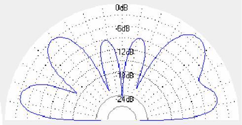
2 Beverage Antenna. Theoretical Look on Practical The Table 1 shows that at all amateur HF s my Beverage Antenna has the gain much below zero. However it is possible compensate at receiving mode by turn on the internal transceiver s preamplifier. At transmitting mode only propagation may help me. However I often received reports at Meter s where the antenna losses are big enough. At the Meter s the report 599 is common one there. It is very interesting that practically measured SWR is close to the theoretical one above the 160- Meter where the some known inaccuracy in simulation is happened. Figure 2 shows SWR of the Beverage Antenna measured with the Rig Expert AA1000. It is very close to the reading by the IC- 718 and to the theoretical calculated by the NEC for MMANA. Another important side of the Beverage Antenna is the Diagram Directivity. Below Figure 3 to Figure 11 show DD of the Beverage Antenna at the 160, 80, 40, 30, 20, 17, 15, 12 and 10- meter s in the vertical plane. Feedline with matching transformer is on the left side and the termination resistor is on the right side of the figures. As you can see from the Figure 3 - Figure 11 the DD of the Beverage Antenna is far away from a perfect one. Antenna has signification radiation into zenith. It is may be not bad for Meter s where it gives local QSOs. However at the higher bands it is just waist of the transmitter power. Figure 2 SWR of the Beverage Antenna shown by the Rig Expert AA1000 Figure 3 DD of my Beverage Antenna at 160- Meter Figure 5 DD of my Beverage Antenna at 40- Meter Figure 4 DD of my Beverage Antenna at 80- Meter Figure 6 DD of my Beverage Antenna at 30- Meter Page- 34


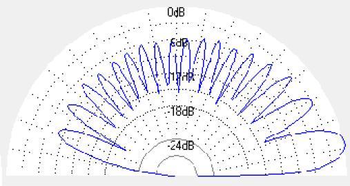
3 Figure 7 DD of my Beverage Antenna at 20- Meter Figure 8 DD of my Beverage Antenna at 17- Meter Figure 9 DD of my Beverage Antenna at 15- Meter Figure 10 DD of my Beverage Antenna at 12- Meter Of course after I have found the theoretical data for my Beverage Antenna I would like to improve the antenna efficiency. Most simple way to improve the efficiency of a broadband Beverage Antenna is to connect to the termination hot end an additional wire with length that is not resonant for the used bands. To find the needed length and possible practical configuration is a not simple task. But I decided to do it. Additional wire in 7 meter length was connected to the antenna load. Figure 12 shows the antenna. Parameters of the antenna were simulated with NEC for MMANA. Table 2 shows the data for my antenna. Maxima gain is given to the radiation angle at where it is. Figure 11 DD of my Beverage Antenna at 10- Meter Figure 12 Beverage Antenna with additional wire at the termination end Page- 35
, simulated with NEC for MMANA and measured practically by SWR- Meter of IC- 718 160 133+J736 80 601+J239 30 12331518 7.")
 near to 3 db at all working s.")

4 Table 2 Data for Beverage Antenna placed at 1.8 meter above the Ground with additional wire at termination side (Figure 12), simulated with NEC for MMANA and measured practically by SWR- Meter of IC J J _ J Z SWR Gain At Vertical degree SWR by IC718 As you can see from the Table 2 additional wire affected my Beverage Antenna. Antenna gain was increased (theoretically) near to 3 db at all working s. However due high SWR I lost middle of HF s- 40, 30 and 20- Meter s. I cannot say that I have noticed significant difference in reception and transmission mode at the rest s. Below Figure 13 to Figure 11 show DD of the Beverage Antenna at the 160, 80, 40, 30, 20, 17, 15, 12 and 10- meter s in the vertical plane. Feedline with matching transformer is on the left side and the termination resistor is on the right side of the figures. DD the Beverage Antenna at 160 and 80 Meter s are practically identical so those ones shown at one figure- Figure 13. As you can see from the Figure 13 - Figure 20 the DD of the Beverage Antenna with additional wire at termination load changed compare to classical Beverage Antenna. In theory the antenna should work better compare to my old one. However the antenna as well has signification radiation into zenith. Figure 13 DD of modified Beverage Antenna with additional wire at termination load at 160 and 80- Meter Figure 14 DD of modified Beverage Antenna with additional wire at termination load at 40- Meter Figure 15 DD of modified Beverage Antenna with additional wire at termination load at 30- Meter Page- 36


 worked very well at 17, 15, 12 and 10 Meter s.")


5 Figure 16 DD of modified Beverage Antenna with additional wire at termination load at 20- Meter Figure 18 DD of modified Beverage Antenna with additional wire at termination load at 15- Meter Figure 17 DD of modified Beverage Antenna with additional wire at termination load at 17- Meter Figure 19 DD of modified Beverage Antenna with additional wire at termination load at 12- Meter Anyway to have an objective appraisal the old and new antenna it needs to do A- B test. I did not do it. Unexpectedly I found that the antenna at some days have received lots industrial electrical interferences. Because of it and because of I need the 40, 30 and 20 meter the antenna was de- configured to the classical design. Though sometimes it seems to me that the antenna (with additional wire) worked very well at 17, 15, 12 and 10 Meter s. May be at some days I return back to experimenters with Beverage Antenna with additional wire at termination load. Next my experiment with my Beverage Antenna was simple. Under the antenna I installed a copper wire that connected together ground at feeding transformer and ground at termination load. Figure 21 shows design of the Beverage Antenna. At early times when I experimented with Beverage Antenna I noticed that such additional wire very often improved efficiency of the Beverage Antenna. Parameters of the antenna were simulated with NEC for MMANA. Table 3 shows the data for the antenna. Maxima gain is given to the radiation angle at where it is. Figure 20 DD of modified Beverage Antenna with additional wire at termination load at 10- Meter Page- 37
6 Figure 21 Beverage Antenna with additional wire between feeding transformer and termination load Table 3 Data for Beverage Antenna placed at 1.8 meter above the Ground with additional wire between feeding transformer and termination load (Figure 21), simulated with NEC for MMANA and measured practically by SWR- Meter of IC- 718 Z j SWR Gain At Vertical degree SWR by IC-718 Theoretical data show that the antenna gain a little improved (above 160- meter where some known inaccuracy at simulation is happened) at the configuration. Below Figure 22 to Figure 30 show DD of the Beverage Antenna at the 160, 80, 40, 30, 20, 17, 15, 12 and 10meter s in the vertical plane. Feedline with matching transformer is on the left side and the termination resistor is on the right side of the figures. As you can see from the Figure 24 - Figure 30 the DD of the Beverage Antenna with additional wire between feeding transformer and termination load looks better compare to my classical Beverage Antenna shown at Figure 1. Theoretical DD at 160 and 80 has more radiation to zenith compare to Beverage Antenna shown at Figure 1. My opinion was that the antenna began work better the classical variant (Figure 1). Page- 38


7 Figure 22 DD of Beverage Antenna with additional wire between feeding transformer and termination load at 160- Meter Figure 23 DD of my Beverage Antenna with additional wire between feeding transformer and termination load at 80- Meter Figure 24 DD of my Beverage Antenna with additional wire between feeding transformer and termination load at 40- Meter Figure 25 DD of my Beverage Antenna with additional wire between feeding transformer and termination load at 30- Meter Figure 26 DD of my Beverage Antenna with additional wire between feeding transformer and termination load at 20- Meter However the configuration gave me unexpected effect. Beverage Antenna began received industrial electrical interferences. Antenna practically was not affected at day time but at evening time the interferences were such very strong that I cannot use 160 and 80- meter s. Sometimes the interferences closed the 40- meter. Figure 27 DD of my Beverage Antenna with additional wire between feeding transformer and termination load at 17- Meter Interferences not disappeared when I disconnected off the wire from any one side of the antenna- from termination load or feeding transformer. Moreover the interferences did not disappeared when the wire was disconnected from the both sides of antenna. I suspected that the ground wire for some reason received interferences from the street light. So, I should return to the old configuration of my Beverage Antenna Page- 39


8 Beverage Antenna. Theoretical Look on Practical Figure 28 Figure 29 DD of my Beverage Antenna with additional wire between feeding transformer and termination load at 15- Meter DD of my Beverage Antenna with additional wire between feeding transformer and termination load at 12- Meter Last possibility to improve the efficiency of the Beverage Antenna could be increasing the height of the horizontal wire to 4- meters above the ground. In theory this way should bring to multi beam DD at the high frequencies bands (because the vertical wires of the antenna take part at creation DD) and to some difference of the antenna impedance from the impedance of the termination load. Figure 31 shows design of the Beverage Antenna with horizontal wire placed at height 4 meter above the ground.. Parameters of the antenna were simulated with NEC for MMANA. Table 4 shows the data for the antenna. Maxima gain is given to the radiation angle at where it is. Theoretical data show that the antenna gain improved at all s. However because the antenna impedance not to be close to the impedance of the termination load there would difficulties with matching of the antenna at 12 and 10- meter s. Figure 30 DD of my Beverage Antenna with additional wire between feeding transformer and termination load at 10- Meter Figure 31 Beverage Antenna with horizontal wire placed at height 4 meter above the ground Page- 40


9 Table 4 Data for Beverage Antenna placed at 4 meter above the Ground (Figure 31), simulated with NEC for MMANA Z J J J J _ _J SWR Gain At Vertical degree Below Figure 32 to Figure 40 show DD of the Beverage Antenna at the 160, 80, 40, 30, 20, 17, 15, 12 and 10meter s in the vertical plane. Feedline with matching transformer is on the left side and the termination resistor is on the right side of the figures. As you can see from the Figure 32 - Figure 40 the DD of the Beverage Antenna with horizontal wire placed at height 4 meter above the ground looks better compare to my classical Beverage Antenna shown at Figure 1. However lost 12 and 10- meter bands and complexity with installation of the horizontal wire did not compensate the new antenna advantages. Figure 32 DD of theoretical Beverage Antenna with horizontal wire placed at height 4 meter above the ground at 160- Meter Figure 34 Figure 33 DD of theoretical Beverage Antenna with horizontal wire placed at height 4 meter above the ground at 80- Meter DD of theoretical Beverage Antenna with horizontal wire placed at height 4 meter above the ground at 40- Meter Page- 41


10 Figure 35 DD of theoretical Beverage Antenna with horizontal wire placed at height 4 meter above the ground at 30- Meter Figure 37 DD of theoretical Beverage Antenna with horizontal wire placed at height 4 meter above the ground at 17- Meter Figure 36 DD of Beverage Antenna with horizontal wire placed at height 4 meter above the ground at 20- Meter Figure 38 DD of theoretical Beverage Antenna with horizontal wire placed at height 4 meter above the ground at 15- Meter Figure 40 Figure 39 DD of theoretical Beverage Antenna with horizontal wire placed at height 4 meter above the ground at 12- Meter DD of theoretical Beverage Antenna with horizontal wire placed at height 4 meter above the ground at 10- Meter Page- 42


11 In conclusion I decided to simulate Beverage Antenna that I used at my amateur station UA3ZNW- UZ3ZK- RK3ZK from to 2002 year in Belgorod, Russia. Figure 41 shows the antenna. The antenna was installed on the parapet of the 9- storey building. Antenna length was 80 meters. The horizontal wire was located at height about 1- meter above the parapet. Antenna wire was stretched on several wooden masts placed near 5 meter from each other. I used the dry trunk from small trees. Transformer of the antenna was made according to Figure 42. Transformer had 7 turns wound by tripled wire on ferrite ring from yoke from Color TV. I have no picture of the original transformer. However it looked like transformer shown on Figure 43. Transformer was placed inside a plastic bag for protection from the weather influences. Termination load of the antenna was made from 18- kom /2- Wtt Russian resistors MLT- 2 (the resistors are still in sell on ebay) that were connected to bridge. The load had resistance 600Ohm. Figure 41 Beverage Antenna used at my amateur station UA3ZNW- UZ3ZK- RK3ZK from to 2002 year Figure 42 Transformer of the Beverage Antenna used at my amateur station UA3ZNW- UZ3ZK- RK3ZK from to 2002 year Figure 43 Transformer 50/450 (75/600) wound by tripled wire on ferrite ring from TV yoke Page- 43
 inside building in ventilation shaft. Termination load was reworked to 450- Ohm.")

 used at my amateur station UA3ZNW- UZ3ZK- RK3ZK from 1990- to 2002 year 160 589+15 80 502+275 40 645-308 30 703-152 20 437-j11 15 507-99 12 361+21 10")
12 Antenna for first several years was feed through 75- Ohm coaxial cable that was going along the building wall. Then I have removed this cable and have installed a new one (50Ohm good coaxial cable) inside building in ventilation shaft. Termination load was reworked to 450- Ohm. SWR of the antenna was not more the 1.5: 1 at all bands with 75 and 50- Ohm coaxial cable. You may find on the Figure 41 address of the building. It seems to me still it is possible to find remains of my antennas on the roof using Google Map Figure 44 DD of Beverage Antenna of amateur station UA3ZNWUZ3ZK- RK3ZK at 160- Meter Antenna worked great on all HF- s from 160 till 10meter band. 160 and 80 meter bands at the antenna were good to communicate with Ham stations from Europe and Asia. Table 5 Data for Beverage Antenna (Figure 41) used at my amateur station UA3ZNW- UZ3ZK- RK3ZK from to 2002 year j J Z SWR Gain At Vertical degree Figure 45 DD of Beverage Antenna of amateur station UA3ZNWUZ3ZK- RK3ZK at 80- Meter Figure 46 DD of Beverage Antenna of amateur station UA3ZNWUZ3ZK- RK3ZK at 40- Meter North America and Japan propagated good above 40meter. Table 5 shows the data for the antenna. Maxima gain is given to the radiation angle at where it is. Figure 44 to Figure 52 show DD of the Beverage Antenna at the 160, 80, 40, 30, 20, 17, 15, 12 and 10- meter s in the vertical plane. Feedline with matching transformer is on the left side and the termination load is on the right side of the figures. As you can see from Figure 44 to Figure 52 the Beverage Antenna has not so bad DD. Page- 44 If you have possibility to install such antenna- do not hesitate. It is easy to install, easy to match, invisible and low noise antenna. 73! de VA3ZNW


13 Figure 47 DD of Beverage Antenna of amateur station UA3ZNWUZ3ZK- RK3ZK at 30- Meter Figure 48 DD of Beverage Antenna of amateur station UA3ZNWUZ3ZK- RK3ZK at 20- Meter Figure 50 Figure 49 DD of Beverage Antenna of amateur station UA3ZNWUZ3ZK- RK3ZK at 17- Meter DD of Beverage Antenna of amateur station UA3ZNWUZ3ZK- RK3ZK at 15- Meter Figure 52 Figure 51 DD of Beverage Antenna of amateur station UA3ZNWUZ3ZK- RK3ZK at 12- Meter DD of Beverage Antenna of amateur station UA3ZNWUZ3ZK- RK3ZK at 10- Meter Page- 45
Figure 1 Broadband indoor antenna
 Igor Grigorov, VA3ZNW E-mail: antentop@antentop.org It was in winter 1994. In that time heavy winter winds destroyed my outdoor antennas. I could not do repairs of the antennas at cold winds and snowdrifts
Bead RF Chokes. By: Igor Grigorov, VA3ZNW, Richmond Hill, Canada
 By: Igor Grigorov, VA3ZNW, Richmond Hill, Canada Recently there are lots devices that contained some RF sensitive or vice versa RF generation parts inside. It is power AC/DC converters (aka power supply),
Two Wires Beverage Antenna
 Igor Grigorov, VA3ZNW was well known in the former USSR where the antenna was widely used on the HF receiving centers both military and civil ones. Prototype of the antenna is described in Reference 1.
Improved Ionospheric Propagation With Polarization Diversity, Using A Dual Feedpoint Cubical Quad Loop
 Improved Ionospheric Propagation With Polarization Diversity, Using A Dual Feedpoint Cubical Quad Loop by George Pritchard - AB2KC ab2kc@optonline.net Introduction This Quad antenna project covers a practical
Technician License. Course
 Technician License Course Technician License Course Chapter 4 Lesson Plan Module - 10 Practical Antennas The Dipole Most basic antenna The Dipole Most basic antenna The Dipole Total length is ½ wavelength
FCC Technician License Course
 FCC Technician License Course 2014-2018 FCC Element 2 Technician Class Question Pool Presented by: Tamiami Amateur Radio Club (TARC) WELCOME To the third of 4, 3-hour classes presented by TARC to prepare
Intermediate Course (5) Antennas and Feeders
 Antennas and Feeders") Intermediate Course (5) Antennas and Feeders 1 System Transmitter 50 Ohms Output Standing Wave Ratio Meter Antenna Matching Unit Feeder Antenna Receiver 2 Feeders Feeder types: Coaxial, Twin Conductors
Intermediate Course (5) Antennas and Feeders 1 System Transmitter 50 Ohms Output Standing Wave Ratio Meter Antenna Matching Unit Feeder Antenna Receiver 2 Feeders Feeder types: Coaxial, Twin Conductors
Thanks to our authors:
 ANTENTOP 01 2015 # 019 ANTENTOP is FREE e-magazine devoted to ANTENna s Theory, 1-2015 Operation, and Practice Edited by hams for hams In the Issue: Antennas Theory! Practical design of HF Antennas! Antenna
Technician Licensing Class T9
 Technician Licensing Class T9 Amateur Radio Course Monroe EMS Building Monroe, Utah January 11/18, 2014 January 22, 2014 Testing Session Valid dates: July 1, 2010 June 30, 2014 Amateur Radio Technician
Antennas and Propagation Chapters T4, G7, G8 Antenna Fundamentals, More Antenna Types, Feed lines and Measurements, Propagation
 Antennas and Propagation Chapters T4, G7, G8 Antenna Fundamentals, More Antenna Types, Feed lines and Measurements, Propagation =============================================================== Antenna Fundamentals
Technician License. Course
 Technician License Course Technician License Course Chapter 4 Lesson Plan Module - 9 Antenna Fundamentals Feed Lines & SWR The Antenna System The Antenna System Antenna: Transforms current into radio waves
ANTENTOP # 015. ANTENTOP is FREE e-magazine devoted to ANTENna s Theory, Operation, and Practice Edited by hams for hams
 ANTENTOP 01 2011 # 015 ANTENTOP is FREE e-magazine devoted to ANTENna s Theory, 1-2011 Operation, and Practice Edited by hams for hams In the Issue: Antennas Theory! Practical design of HF Antennas! Underground
Technician Licensing Class. Antennas
 Technician Licensing Class Antennas Antennas A simple dipole mounted so the conductor is parallel to the Earth's surface is a horizontally polarized antenna. T9A3 Polarization is referenced to the Earth
4/25/2012. Supplement T9. 2 Exam Questions, 2 Groups. Amateur Radio Technician Class T9A: T9A: T9A: T9A:
 Amateur Radio Technician Class Element 2 Course Presentation ti ELEMENT 2 SUB-ELEMENTS Technician Licensing Class Supplement T9 Antennas, Feedlines 2 Exam Questions, 2 Groups T1 - FCC Rules, descriptions
A Stub Matched Lazy H for 17 M
 A Stub Matched Lazy H for 17 M Introduction The author has experimented with various configurations of the classic Lazy H antenna and a version optimised for operation on the 17 M band is shown in Figure
Radio Signals out of Our Times
 By: Igor Grigorov, VA3ZNW Credit Line: www.cqham.ru In our material world sometimes there are events, which are not correspond to ours knowledge about the world. For example, there are evidences that things
4/29/2012. General Class Element 3 Course Presentation. Ant Antennas as. Subelement G9. 4 Exam Questions, 4 Groups
 General Class Element 3 Course Presentation ti ELEMENT 3 SUB ELEMENTS General Licensing Class Subelement G9 Antennas and Feedlines 4 Exam Questions, 4 Groups G1 Commission s Rules G2 Operating Procedures
Technician License Course Chapter 4. Lesson Plan Module 9 Antenna Fundamentals, Feed Lines & SWR
 Technician License Course Chapter 4 Lesson Plan Module 9 Antenna Fundamentals, Feed Lines & SWR The Antenna System Antenna: Transforms current into radio waves (transmit) and vice versa (receive). Feed
SWR myths and mysteries.
 SWR myths and mysteries. By Andrew Barron ZL3DW September 2012 This article will explain some of the often misunderstood facts about antenna SWR at HF and uncover some popular misconceptions. The questions
Transforms and electrical signal into a propagating electromagnetic wave OR vise versa. - Transducer goes both ways. TX and RX antennas have
 Gary Rondeau AF7NX Transforms and electrical signal into a propagating electromagnetic wave OR vise versa. - Transducer goes both ways. TX and RX antennas have different jobs. For TX want to generate as
Sometimes for grounded antennas is used a usual horizontal dipole antenna located straight over the ground. Page-16
 Chapter from the book: Alpert, Bulatov, Runge: Antennas of the Third Reich: Published by Ministry of Defense of the USSR, Moscow, 1948. (Circulation: 300 copies). Credit line: http://www.radioscanner.ru/files/antennas/file10355/
Contesting with Verticals & VDAs. Pete VE3IKV / VA3RA / VP2EAT
 Pete VE3IKV / VA3RA / VP2EAT Verticals means both gain-type HF monoband verticals and vertical directional arrays (VDAs) Object is to keep the main vertical radiation pattern as low as possible (
Figure 1 Parameters of the Antenna UA6AGW V.40.0
 Aleksandr Grachev, UA6AGW Credit Line: CQ-QRP # 39, pp.: 22-27. In the summer 2011, UA6AGW persistently have been working on improvement of his antennas (see Reference 1). Article below is just a digest
Antennas and Stuff. John Kernkamp WB4YJT
 Antennas and Stuff John Kernkamp WB4YJT John Kraus W8JK June 28, 1910 - July 18, 2004 Invented the helical antenna, the corner reflector, and the W8JK End-Fire array. In 1950 designed and built the Big
Magnetic Loop Antenna - Topbands
 Magnetic Loop Antenna - Topbands Instruction Manual Thank you for purchasing this new product small Magnetic Loop Antenna Topbands. Manual contains important information. Please read all instructions carefully
Technician License Course Chapter 4
 Technician License Course Chapter 4 Propagation, Basic Antennas, Feed lines & SWR K0NK 26 Jan 18 The Antenna System Antenna: Facilitates the sending of your signal to some distant station. Feed line: Connects
LCL, Radiation, and Radiation Resistance
 LCL, Radiation, and Radiation Resistance Some thoughts on how to determine antenna or cable radiation, ideas which may not necessarily represent the opinion of IARU At first we should have a look at Fig
Bob Brehm, AK6R Chief Engineer Palomar-Engineers.com
 Bob Brehm, AK6R Chief Engineer Palomar-Engineers.com LAKESIDE - October 2017 This presentation available on website Copyright 2013-2017 Palomar Engineers, Inc. End Fed Workshop Topics Popular End Fed Antenna
Credit Line: Forum from:
 The publication is devoted to the memory UR0GT. By: Nikolay Kudryavchenko, UR0GT Credit Line: Forum from: www.cqham.ru www.radioscanner.ru Antenna Shaiba (from Russian to English Shaiba is a hockey puck)
N0GW Log Periodic Installation
 N0GW Log Periodic Installation I am particularly happy with my HF log periodic beam antenna installation. This is my first tower mounted, rotatable, beam antenna. Before retiring and moving to the Ozarks,
Magnetic Loop Antenna - Top Bands
 Magnetic Loop Antenna - Top Bands Instruction Manual Thank you for purchasing this new product small Magnetic Loop Antenna Top Bands. Manual contains important information. Please read all instructions
G7FEK LIMITED SPACE ANTENNA
 80, 40, 30, 17, 15, 12 m see tet for 20 & 10m operation For 20m operation add red wire 16.5ft ( 5.1m) 24 ft (7.4m) Copyright 2009 G7FEK During the 1980s Mike, G7FEK, described a limited space antenna suitable
COAXIAL TRANSMISSION LINE COMMON-MODE CURRENT
 COAXIAL TRANSMISSION LINE COMMON-MODE CURRENT Introduction Coaxial transmission lines are popular for their wide frequency bandwidth and high resistance to electromagnetic interference (EMI). Coax cables
A SHORT TWO-WAY BEVERAGE ANTENNA PROJECT. By Phil Anderson, WØXI
 A SHORT TWO-WAY BEVERAGE ANTENNA PROJECT By Phil Anderson, WØXI I live in a suburban neighborhood and about two blocks from a shopping center. The city population is nearly 100,000. As such, you can imagine
Half-Wave Dipole. Radiation Resistance. Antenna Efficiency
 Antennas Simple Antennas Isotropic radiator is the simplest antenna mathematically Radiates all the power supplied to it, equally in all directions Theoretical only, can t be built Useful as a reference:
CHAPTER 8 ANTENNAS 1
 CHAPTER 8 ANTENNAS 1 2 Antennas A good antenna works A bad antenna is a waste of time & money Antenna systems can be very inexpensive and simple They can also be very expensive 3 Antenna Considerations
Bob Brehm, AK6R Chief Engineer Palomar-Engineers.com
 Bob Brehm, AK6R Chief Engineer Palomar-Engineers.com HAMCON 2017 - September 2017 This presentation available on website Copyright 2013-2017 Palomar Engineers, Inc. End Fed Workshop Topics Popular End
Antenna Design for FM-02
 Antenna Design for FM-02 I recently received my FM-02 FM transmitter which I purchased from WLC. I researched the forum on what antennas where being used by the DIY community and found a nice write-up
Fundamentals of Antennas. Prof. Ely Levine
 Fundamentals of Antennas Prof. Ely Levine levineel@zahav.net.il 1 Chapter 3 Wire Antennas 2 Types of Antennas 3 Isotropic Antenna Isotropic radiator is the simplest antenna mathematically Radiates all
RX Directional Antennas. Detuning of TX Antennas.
 1. Models Impact of Resonant TX antennas on the Radiation Pattern of RX Directional Antennas. Detuning of TX Antennas. Chavdar Levkov, lz1aq@abv.bg, www.lz1aq.signacor.com 2-element small loops and 2-element
4 Antennas as an essential part of any radio station
 4 Antennas as an essential part of any radio station 4.1 Choosing an antenna Communicators quickly learn two antenna truths: Any antenna is better than no antenna. Time, effort and money invested in the
2-element Single Mast Wire Beam with 4 Switchable Directions
 2-element Single Mast Wire Beam with 4 Switchable Directions Chavdar Levkov Jr. LZ1ABC, ch.levkov@gmail.com, Chavdar Levkov LZ1AQ, lz1aq@abv.bg We need a directional antenna field day style for 20 m band.
Technician Licensing Class. Lesson 4. presented by the Arlington Radio Public Service Club Arlington County, Virginia
 Technician Licensing Class Lesson 4 presented by the Arlington Radio Public Service Club Arlington County, Virginia 1 Quiz Sub elements T6 & T7 2 Good Engineering Practice Sub element T8 3 A Basic Station
Emergency Antennas. Presented by Ham Hilliard W4GMM
 Emergency Antennas Presented by Ham Hilliard W4GMM Dipole antenna Vertical antenna Random wire antenna Dipole antenna The half wave dipole antenna consists of a conductive wire or rod that is half the
Install as much wire/tubing as possible Electrically short antennas Minimize matching losses Good ground for verticals Maximizes antenna efficiency
 Jim Wolf KR9U Install as much wire/tubing as possible Electrically short antennas Minimize matching losses Good ground for verticals Maximizes antenna efficiency Far-away ground conditions determine low
An Introduction to Radio Frequency Interference
 An Introduction to Radio Frequency Interference Ron Hranac, N0IVN Member, ARRL EMC Committee ARRL Colorado Section Technical Specialist What is RFI? RFI is an abbreviation for radio frequency interference
Cray Valley Radio Society. Real Life Wire Antennas
 Cray Valley Radio Society Real Life Wire Antennas 1 The basic dipole The size of an antenna is determined by the wavelength of operation In free space: ~3x10 8 m/s Frequency x Wavelength = Speed of Light,
Development of a noval Switched Beam Antenna for Communications
 Master Thesis Presentation Development of a noval Switched Beam Antenna for Communications By Ashraf Abuelhaija Supervised by Prof. Dr.-Ing. Klaus Solbach Institute of Microwave and RF Technology Department
Lesson 11: Antennas. Copyright Winters Version 1.0. Preparation for Amateur Radio Technician Class Exam
 Lesson 11: Antennas Preparation for Amateur Radio Technician Class Exam Topics Antenna ½ wave Dipole antenna ¼ wave Vertical antenna Antenna polarization Antenna location Beam antennas Test Equipment Exam
4.4. Experimental Results and Analysis
 4.4. Experimental Results and Analysis 4.4.1 Measurement of the IFA Against a Large Ground Plane The Inverted-F Antenna (IFA) discussed in Section 4.3.1 was modeled over an infinite ground plane using
ANTENNAS. I will mostly be talking about transmission. Keep in mind though, whatever is said about transmission is true of reception.
 Reading 37 Ron Bertrand VK2DQ http://www.radioelectronicschool.com ANTENNAS The purpose of an antenna is to receive and/or transmit electromagnetic radiation. When the antenna is not connected directly
City-Windom Antenna History.
 City-Windom Antenna History. Evgeniy Slodkevich, UA3AHM The VS1AA antenna made by an American named Windom (1936) had been the ancestor of City Windom. It was often called Amerikanka in the Soviet Union,
The Fabulous Dipole. Ham Radio s Most Versatile Antenna
 The Fabulous Dipole Ham Radio s Most Versatile Antenna 1 What is a Dipole? Gets its name from its two halves One leg on each side of center Each leg is the same length It s a balanced antenna The voltages
Magnetic Loop Antenna - Multiband
 Magnetic Loop Antenna - Multiband Instruction Manual Thank you for purchasing this new product small Magnetic Loop Antenna Multiband. Manual contains important information. Please read all instructions
Milton Keynes Amateur Radio Society (MKARS)
") Milton Keynes Amateur Radio Society (MKARS) Intermediate Licence Course Feeders Antennas Matching (Worksheets 31, 32 & 33) MKARS Intermediate Licence Course - Worksheet 31 32 33 Antennas Feeders Matching
Milton Keynes Amateur Radio Society (MKARS) Intermediate Licence Course Feeders Antennas Matching (Worksheets 31, 32 & 33) MKARS Intermediate Licence Course - Worksheet 31 32 33 Antennas Feeders Matching
Technician License Course Chapter 4. Lesson Plan Module 10 Practical Antennas
 Technician License Course Chapter 4 Lesson Plan Module 10 Practical Antennas The Dipole Most basic antenna Total length is ½ wavelength (½ λ) Usual construction: Two equal halves of wire, rod, or tubing
SOME USES FOR RF1,RF5 and VA1 ANALYSTS. SWR Measurement
 SOME USES FOR RF1,RF5 and VA1 ANALYSTS THE HANDIEST INSTRUMENTS IN DECADES! When you put up an antenna in the the old days, it could be a real struggle. The only way to tell if it was tuned to the right
A Tri Band Antenna for 2 meters, 220 MHz, and 70cm Antenna Without Radials. By: Edison Fong (WB6IQN)
") A Tri Band Antenna for 2 meters, 220 MHz, and 70cm Antenna Without Radials By: Edison Fong (WB6IQN) Twenty years ago a single band handie talkie would have been adequate for emergency use since almost
A Tri Band Antenna for 2 meters, 220 MHz, and 70cm Antenna Without Radials By: Edison Fong (WB6IQN) Twenty years ago a single band handie talkie would have been adequate for emergency use since almost
Welcome to Ham Radio 201 New General / Extra Session
 Welcome to Ham Radio 201 New General / Extra Session Sponsored by Agenda New Technician / New Licensee 8:00 Kickoff 8:15 VHF/UHF Gear - George 9:00 VHF/UHF Operating - Beric 9:45 VHF Digital Voice George
HF Wire Antennas with Gain
 Learning Unit 5 HF Wire Antennas with Gain Objectives and Overview: Take the student to the next step beyond the half-wave dipole and introduce wire antennas with enhanced directivity and gain. The concept
Basic Wire Antennas. Part II: Loops and Verticals
 Basic Wire Antennas Part II: Loops and Verticals A loop antenna is composed of a single loop of wire, greater than a half wavelength long. The loop does not have to be any particular shape. RF power can
Array Solutions WX0B StackMatch User's Guide
 Array Solutions WX0B StackMatch User's Guide Thank you for purchasing the StackMatch. It has become a standard for phasing monoband and multi-band antennas.. The unit comes with our Life Time Warranty.
M2 Antenna Systems, Inc. Model No: 2M HO LOOP
 M2 Antenna Systems, Inc. Model No: 2M HO LOOP SPECIFICATIONS: Model... 2M HO LOOP Frequency Range... 144 To 144.5 MHz Gain, Typical @ 10 ft.... 4 dbd @ 10 deg. Gain, 2 STK @ 82 & 132... 8 dbd @ 9 deg.
SWL Receiving Antenna Experiments
 SWL Receiving Antenna Experiments Introduction I have a lot to learn about SWL antennas. What follows are some brief experiments I performed in late October 2005. I have been experimenting with a half
MFJ-219/219N 440 MHz UHF SWR Analyzer TABLE OF CONTENTS
 MFJ-219/219N 440 MHz UHF SWR Analyzer TABLE OF CONTENTS Introduction...2 Powering The MFJ-219/219N...3 Battery Installation...3 Operation Of The MFJ-219/219N...4 SWR and the MFJ-219/219N...4 Measuring
MQ-24SR Miniature Four band Hybrid Quad Antenna
 MQ-24SR Miniature Four band Hybrid Quad Antenna Most antennas are large heavy structures requiring heavy duty structures, rotors and lots of extra muscle during installation and lots of extra dollars before
General Class License Theory III. Dick Grote K6PBF
 General Class License Theory III Dick Grote K6PBF K6pbfdick@gmail.com 1 Introduction In this session we will learn about: Feed Lines Antennas Safety As in the other theory classes, we will try to present
1) Transmission Line Transformer a. First appeared on the scene in 1944 in a paper by George Guanella as a transmission line transformer, the 1:1
 Transmission Line Transformer a. First appeared on the scene in 1944 in a paper by George Guanella as a transmission line transformer, the 1:1") 1) Transmission Line Transformer a. First appeared on the scene in 1944 in a paper by George Guanella as a transmission line transformer, the 1:1 Guanella Balun is the basic building Balun building block.
1) Transmission Line Transformer a. First appeared on the scene in 1944 in a paper by George Guanella as a transmission line transformer, the 1:1 Guanella Balun is the basic building Balun building block.
THE VK WINDOM. Seemed Like a Good Idea
 THE VK WINDOM Seemed Like a Good Idea Over the years there have been many articles about the Windom antenna. It was first popularized by a US amateur called Windom whose 40 m signal on this antenna was
Feed Line Currents for Neophytes.
 Feed Line Currents for Neophytes. This paper discusses the sources of feed line currents and the methods used to control them. During the course of this paper two sources of feed line currents are discussed:
Table of Contents. MFJ-1778 G5RV Multiband Antenna
 Table of Contents MFJ-1778 G5RV Multiband Antenna Introduction... 1 Theory Of Operation... 1 80 meter band:... 1 40 meter band:... 1 30 meter band:... 2 20 meter band:... 2 17 meter band:... 2 15 meter
Modifying an IC735 for the 630m band 2014 Jacek Lipkowski SQ5BPF
 Modifying an IC735 for the 630m band 2014 Jacek Lipkowski SQ5BPF The IC735 is a very versatile transceiver, which can be obtained for a good price and is easy to modify and fix.
Coming next: Wireless antennas for beginners
 Coming next: Wireless antennas for beginners In other rooms: Logbook of the World (Sussex Suite) SO2R contest operation (Stable Suite) Wires for your wireless: Simple wire antennas for beginners dominic
Coaxial Cable Feeder Influence on Four Stacked Yagi Antennas Array Dragoslav Dobričić, YU1AW
 Coaxial Cable Feeder Influence on Four Stacked Yagi Antennas Array Dragoslav Dobričić, YU1AW dragan@antennex.com Introduction Aprevious article series consisted of two parts [1, 2] showing the results
Made in Russia. By Serge V. Satyr, RW3XA (ex: UA3XBY), Obninsk, Russia Credit Line:
, Obninsk, Russia Credit Line:") By Serge V. Satyr, RW3XA (ex: UA3XBY), Obninsk, Russia rw3xa@qsl.net Translated by RW3XW Credit Line: http://www.feerc.obninsk.org/rw3xa/ant/gpxa_en.htm Made in Russia As a rule, we need taking some steps
By Serge V. Satyr, RW3XA (ex: UA3XBY), Obninsk, Russia rw3xa@qsl.net Translated by RW3XW Credit Line: http://www.feerc.obninsk.org/rw3xa/ant/gpxa_en.htm Made in Russia As a rule, we need taking some steps
Amateur Radio License. Propagation and Antennas
 Amateur Radio License Propagation and Antennas Todays Topics Propagation Antennas Propagation Modes Ground wave Low HF and below, ground acts as waveguide Line-of-Sight (LOS) VHF and above, radio waves
Least understood topics by most HAMs RF Safety Ground Antennas Matching & Feed Lines
 Least understood topics by most HAMs RF Safety Ground Antennas Matching & Feed Lines Remember this question from the General License Exam? G0A03 (D) How can you determine that your station complies with
SPECTRACOM MODEL 8165 DISCIPLINED OSCILLATOR ANTENNA INSTALLATION TABLE OF CONTENTS
 SPECTRACOM MODEL 8165 DISCIPLINED OSCILLATOR ANTENNA INSTALLATION TABLE OF CONTENTS Page 1.0 INTRODUCTION... 1 1.3 MODEL 8206A LOOP ANTENNA... 1 1.4 MODEL 8208 WHIP ANTENNA... 4 1.5 ANTENNA LOCATION...
Portable or Emergency VHF Antennas Paul R. Jorgenson KE7HR
 For emergency or public service events it is often necessary to have more antenna than the rubber duck on your handheld VHF radio. Nearly ANY external antenna will provide more coverage for your handheld
Amateur Extra Manual Chapter 9.4 Transmission Lines
 9.4 TRANSMISSION LINES (page 9-31) WAVELENGTH IN A FEED LINE (page 9-31) VELOCITY OF PROPAGATION (page 9-32) Speed of Wave in a Transmission Line VF = Velocity Factor = Speed of Light in a Vacuum Question
Impacts from Non-resonant Conductive Objects on RX Directional Antennas
 Impacts from Non-resonant Conductive Objects on RX Directional Antennas Rev.1.0, January 2017 Chavdar Levkov, lz1aq@abv.bg, www.lz1aq.signacor.com Radiation patterns of 2-element receiving phased arrays
Chapter 6 Antenna Basics. Dipoles, Ground-planes, and Wires Directional Antennas Feed Lines
 Chapter 6 Antenna Basics Dipoles, Ground-planes, and Wires Directional Antennas Feed Lines Some General Rules Bigger is better. (Most of the time) Higher is better. (Most of the time) Lower SWR is better.
JC-5 4KW PEP, 1KW RMS AUTO ANTENNA COUPLER
 JC-5 4KW PEP, 1KW RMS AUTO ANTENNA COUPLER 1) DIRECTLY CONTROLLED BY ICOM, ALINCO & KENWOOD. 2) INDEPENDENT CAPACITOR INPUT AND OUTPUT BLOCKS! 3) 3 mm COIL WIRE & INTERNAL FAN FOR THE BIG COILS! 4) DIPPED
NTT DOCOMO Technical Journal. 1. Introduction. 2. Features of an Activeantenna. 2.1 Basic Configuration of Base Station using an Active Antenna
 Active Antenna for More Advanced and Economical Radio Base Stations Base Station Active antennas that integrate radio transceiver functions in the antenna unit have been attracting attention as an approach
I recently came across a No-Counterpoise antenna described by designed by Peter Millis M3KXZ and based on an original design by K9ESE.
 M3KXZ 'no counterpoise' antenna I recently came across a No-Counterpoise antenna described by designed by Peter Millis M3KXZ and based on an original design by K9ESE. Details of the antenna can be found
Inexpensive Lightweight High-Performance Small Yagi Antennas for VHF-UHF Portable Operation
 Inexpensive Lightweight High-Performance Small Yagi Antennas for VHF-UHF Portable Operation Rick Campbell KK7B Pacific Northwest VHF Conference Bend, Oregon October 8 2016 But why? We already have: Inexpensive
RigExpert AA-170 Antenna Analyzer (0.1 to 170 MHz) User s manual
 User s manual") RigExpert AA-170 Antenna Analyzer (0.1 to 170 MHz) User s manual Table of contents 1. Description... 3 2. Specifications... 4 3. Precautions... 5 4. Operation... 6 4.1. Preparation for use... 6 4.2. Turning
RigExpert AA-170 Antenna Analyzer (0.1 to 170 MHz) User s manual Table of contents 1. Description... 3 2. Specifications... 4 3. Precautions... 5 4. Operation... 6 4.1. Preparation for use... 6 4.2. Turning
UNIT Write short notes on travelling wave antenna? Ans: Travelling Wave Antenna
 UNIT 4 1. Write short notes on travelling wave antenna? Travelling Wave Antenna Travelling wave or non-resonant or aperiodic antennas are those antennas in which there is no reflected wave i.e., standing
Optimizing Your Stations Performance
 Optimizing Your Stations Performance A few hints / techniques, recommendations for getting the most RF out to the Antenna from your HF, VHF / UHF station. Tonights Presenters: Doug Theriault NO1D John
Remote Controller. (Controller: Provided in kit form) * Power Supply Required: Approx. 13VDC 0.2~0.4A (Not Required for CD160Jr)
 * Power Supply Required: Approx. 13VDC 0.2~0.4A (Not Required for CD160Jr)") 1.8MHz(3-CH),1.9MHz(1-CH) 1.8/1.9MHz Super-Compact Dipole Antenna CD160-x, CD160L Model CD160 Antenna Tuning Unit BS83 Remote Controller (Controller: Provided in kit form) * Power Supply Required: Approx.
1.8MHz(3-CH),1.9MHz(1-CH) 1.8/1.9MHz Super-Compact Dipole Antenna CD160-x, CD160L Model CD160 Antenna Tuning Unit BS83 Remote Controller (Controller: Provided in kit form) * Power Supply Required: Approx.
DO NOT COPY. Basic HF Antennas. Bill Shanney, W6QR
 Basic HF Antennas Bill Shanney, W6QR When I was first licensed in 1961 I didn t know much about antennas. I put up the longest wire that fit on my parent s lot at the lofty height of 25 and fed it with
Hamelectronicsmagazine.com / earlandrews.com **** mirror sites **** since FREE ON-LINE MAGAZINE and mail order parts as well!
 LNR PRECISION ---> QUAD BAND END FED HALF WAVE WIRE ANTENNA. -- VE3AB Earl Andrews - NEW REVISED ARTICLE: (OCT 2-2014). I previously had two wires attached to the matchbox in effort to try and get multiband
Weekend Antennas No. 5 The "Compact Quad" Multiband Antenna
 Weekend Antennas No. 5 The "Compact Quad" Multiband Antenna When I relocated to Johannesburg I needed a new multiband HF antenna. Since I was staying in a rented house a tower was out of the question,
General License Class Chapter 6 - Antennas. Bob KA9BHD Eric K9VIC
 General License Class Chapter 6 - Antennas Bob KA9BHD Eric K9VIC Learning Objectives Teach you enough to get all the antenna questions right during the VE Session Learn a few things from you about antennas
A TRANSMISSION LINE BALANCE TEST METER
 by Lloyd Butler VK5BR with modifications by Phil Storr VK5SRP. Here is a simple meter to check the balance of currents running in the two legs of a transmission line. It can be used to check the balance
Range Considerations for RF Networks
 TI Technology Days 2010 Range Considerations for RF Networks Richard Wallace Abstract The antenna can be one of the most daunting components of wireless designs. Most information available relates to large
Using the Buddipole as a Balanced- Fed Doublet 1
 Using the Buddipole as a Balanced- Fed Doublet 1 Les Gasser, W9XC Version 4.1: July 15, 2011 Abstract The well- known Buddipole antenna is a "construction kit" commonly configured into an asymmetrical
Jacques Audet VE2AZX. Nov VE2AZX 1
 Jacques Audet VE2AZX VE2AZX@amsat.org Nov. 2006 VE2AZX 1 - REASONS FOR USING A BALUN - TYPES OF BALUNS - CHECK YOUR BALUN WITH AN SWR ANALYZER - MEASURING THE IMPEDANCE OF A NUMBER OF FERRITES - IMPEDANCE
User Guide for the Alpha Antenna 6 40 or meter OCF Dipole
 User Guide for the Alpha Antenna 6 40 or 10 80 meter OCF Dipole Manufactured by: Alpha Antenna 1.888.482.3249 Website: http://alphaantenna.com User Guide Version 3.0 March 23, 2018 Page 1 Table of Contents
stacking broadside collinear
 stacking broadside collinear There are three primary types of arrays, collinear, broadside, and endfire. Collinear is pronounced co-linear, and we may think it is spelled colinear, but the correct spelling