Nautical Autonomous System with Task Integration
|
|
|
- Rafe Fleming
- 5 years ago
- Views:
Transcription
1 Nautical Autonomous System with Task Integration (code name NASTI) Students: Terry Max Christy, Jeremy Borgman Advisors: Dr. Gary Dempsey, Nick Schmidt 1
2 Outline Original Goals System Overview Review of Completed Work Motor Interfacing Module Communication RC Control Embedded System Image Processing Path Planning Results 2
3 Outline Original Goals System Overview Review of Completed Work Motor Interfacing Module Communication RC Control Embedded System Image Processing Path Planning Results 3 3
4 Background Information 4 4
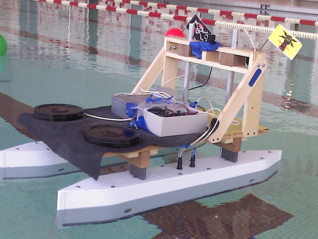
5 NASTI 5 5
6 Outline Original Goals System Overview Review of Completed Work Motor Interfacing Module Communication RC Control Embedded System Image Processing Path Planning Results 6 6

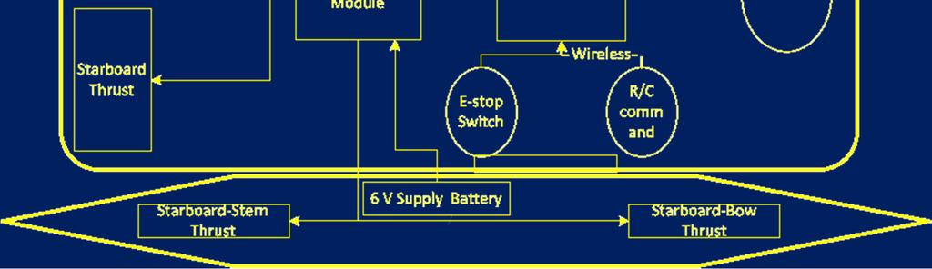
7 System Overview 7 7
8 Outline Original Goals System Overview Review of Completed Work Motor Interfacing Module Communication RC Control Embedded System Image Processing Path Planning Results 8 8
9 9 9
10 Thruster
11 Thruster 3 Thruster 1 Thruster 4 Thruster
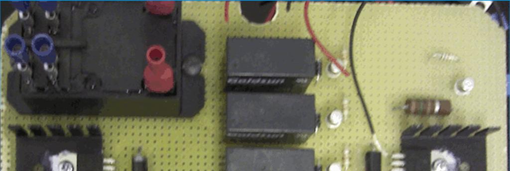
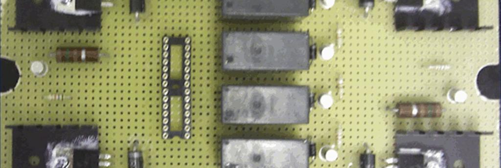
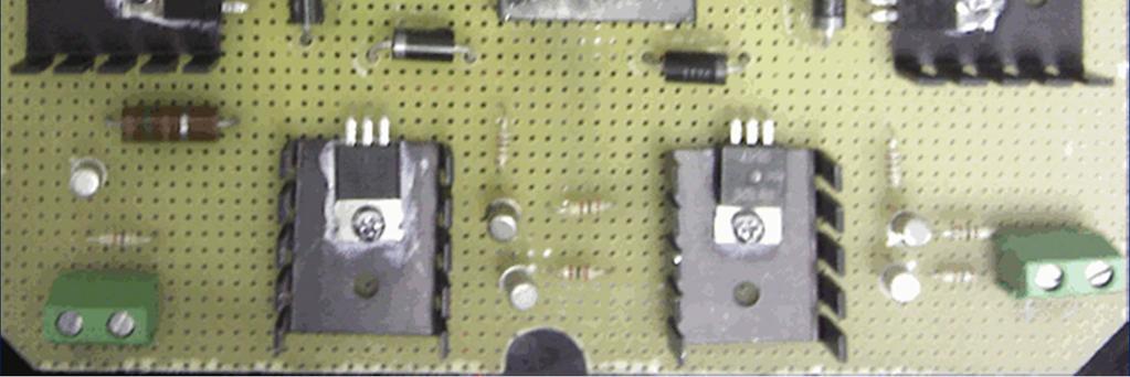
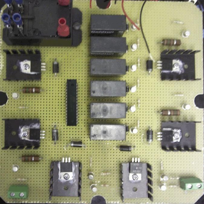
12 Thruster Circuitry 12 12
13 Thruster 3 Thruster 1 Thruster 4 Thruster 2 Left Drive 13 13
14 Thruster 3 Thruster 1 Thruster 4 Thruster 2 Left Drive Right Drive 14 14

15 Main Drive Circuitry 15 15
16 Thruster 1 Direction Control Thruster 3 Thruster 4 Thruster 2 Left Drive Right Drive 16 16

17 Bi-Directional Motor Control Vcc Vcc + - M R1 R
18 Bi-Directional Motor Control Vcc + - M R
19 Bi-Directional Motor Control Vcc + - M R
20 Bi-Directional Motor Control Vcc + - M R
21 Bi-Directional Motor Control Vcc + - M R
22 Bi-Directional Motor Control Vcc - + M R
23 Master POWER Thruster 1 Direction Control Thruster 3 Thruster 4 Thruster 2 Left Drive Right Drive 23 23
24 Master POWER Thruster 1 AtMega 368 Direction Control Thruster 3 Thruster 4 Thruster 2 Left Drive Right Drive 24 24
25 Outline Original Goals System Overview Review of Completed Work Motor Interfacing Module Communication RC Control Embedded System Image Processing Path Planning Results 25 25

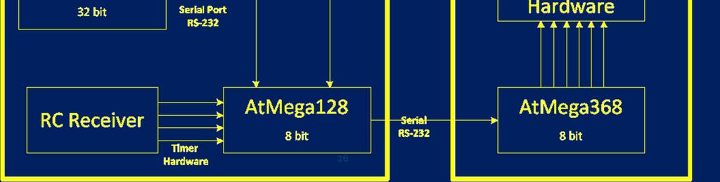
26 Communication Overview 26 26
27 Master AtMega 128 Remote Control Output 50Hz Servo Signal PWM Output 0 99% 1KHz PWM Atmega128 Direction Output 0 5v GPIO 27 27
28 Servo Signals Forward Backward w1 w1 w2 Threshold w4 Threshold w3 w
29 Communication Protocol * * * M0 M1 M2 M3 M4 M5 3 Byte Header Packet 6 Byte Motor Info Packet bits for PWM resolution 1 bit for direction 29 29
30 Outline Original Goals System Overview Review of Completed Work Motor Interfacing Module Communication RC Control Embedded System Image Processing Path Planning Results 30 30
31 R/C Control 31 31
32 R/C Control 32 32
33 R/C Control 33 33
34 R/C Control 34 34
35 R/C Control 35 35

36 R/C Control 36 36
37 R/C Control 37 37
38 R/C Control 38 38
39 Outline Original Goals System Overview Review of Completed Work Motor Interfacing Module Communication RC Control Embedded System Image Processing Path Planning Results 39 39

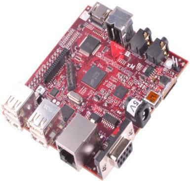
40 Beagleboard Overview 40 40
41 Used Narcissus image builder to create low profile custom image Configured serial port for remote programming Set up Samba server for remote login via PuTTy Installed kernel modules for webcam/wireless adapter Beagleboard Installed and configured opencv Learned how to write makefiles for multifile compiling 41 41
42 Outline Original Goals System Overview Review of Completed Work Motor Interfacing Module Communication RC Control Embedded System Image Processing Path Planning Results 42 42
43 43 Image Processing Receive Target Image Convert Image to HSV Color Space Filter via Thresholding 43 cverode/ cvdialate Blob Detection Store Buoy Information in an array of buoy structures

44 44 Image Processing Receive Target Image Convert Image to HSV Color Space Filter via Thresholding 44 cverode/ cvdialate Blob Detection Store Buoy Information in an array of buoy structures
45 45 Image Processing Receive Target Image Convert Image to HSV Color Space Filter via Thresholding 45 cverode/ cvdialate Blob Detection Store Buoy Information in an array of buoy structures
46 46 Image Processing Receive Target Image Convert Image to HSV Color Space Filter via Thresholding 46 cverode/ cvdialate Blob Detection Store Buoy Information in an array of buoy structures

47 47 Image Processing Receive Target Image Convert Image to HSV Color Space Filter via Thresholding 47 cverode/ cvdialate Blob Detection Store Buoy Information in an array of buoy structures
48 48 Image Processing Receive Target Image Convert Image to HSV Color Space Filter via Thresholding 48 cverode/ cvdialate Blob Detection Store Buoy Information in an array of buoy structures
49 49 Image Processing 49
50 Outline Original Goals System Overview Review of Completed Work Motor Interfacing Module Communication RC Control Beagle Board Image Processing Path Planning Results 50 50

51 51 Path Planning 51
52 52 Image Processing 52
53 53 Path Planning 53


54 Control Block Diagram Forward Path 54 54
55 Outline Original Goals System Overview Review of Completed Work Motor Interfacing Module Communication RC Control Beagle Board Image Processing Path Planning Results 55 55
56 Path Planning 56 56
57 Results 57 57

58 Questions? 58 58


59 HSV chart 59 59

60 Serial Communication TTL vs RS-232 voltage levels Three pins RX, TX, and GND Multiple Baud Rates Baud Rate vs Bit Rate Computing Baud Rate error Baud rate test method 60 60
61 Circuit Calculation Ic2 = Ib2 = 67mA Thruster 1 Ib1 =.7mA + 0.3V V - Ic2 = 1.5A 61 61
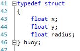
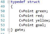
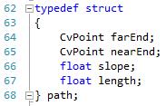
62 Structures 62 62
63 Degrees of Freedom 63 63
64 Floating point values BeagleBoard is 32 bit ->32 bit value. Same as int, less than a double +-3.4*10^+-38 roughly 7 bits of precision ARM A8 contains a NEON coprocessor Dedicated to floating point operations 1 instruction/cycle 64
65 Sources [1] The Five Card Draw" 5th RoboBoat Competition - Preliminary Rules Arlington, VA: AUVSIfoundation. PDF
Nautical Autonomous System with Task Integration
 Nautical Autonomous System with Task Integration Authors: Jeremy Borgman, Terry Max Christy, Zackary Knoll, Steven Blass Advisors: Dr. Gary Dempsey & Mr. Nick Schmidt Department of Electrical Engineering
Nautical Autonomous System with Task Integration (Code name)
") Nautical Autonomous System with Task Integration (Code name) NASTI 10/6/11 Team NASTI: Senior Students: Terry Max Christy, Jeremy Borgman Advisors: Nick Schmidt, Dr. Gary Dempsey Introduction The Nautical
Nautical Autonomous System with Task Integration (Code name) NASTI 10/6/11 Team NASTI: Senior Students: Terry Max Christy, Jeremy Borgman Advisors: Nick Schmidt, Dr. Gary Dempsey Introduction The Nautical
Terry Max Christy & Jeremy Borgman Dr. Gary Dempsey & Nick Schmidt November 29, 2011
 P r o j e c t P r o p o s a l 0 Nautical Autonomous System with Task Integration Project Proposal Terry Max Christy & Jeremy Borgman Dr. Gary Dempsey & Nick Schmidt November 29, 2011 P r o j e c t P r
Autonomous Robotic Boat Platform
 Autonomous Robotic Boat Platform Team: Ryan Burke, Leah Cramer, Noah Dupes, & Darren McDannald Advisors: Mr. Nick Schmidt, Dr. José Sánchez, & Dr. Gary Dempsey Department of Electrical and Computer Engineering
DASL 120 Introduction to Microcontrollers
 DASL 120 Introduction to Microcontrollers Lecture 2 Introduction to 8-bit Microcontrollers Introduction to 8-bit Microcontrollers Introduction to 8-bit Microcontrollers Introduction to Atmel Atmega328
Product Specification
 Ultrasonic Distance Measurement Module Part Number: UM0090-000 Model Number: FA01T04-UM0090-000 Overview The measures the time interval between emitting the ultrasonic pulses and receiving the echo to
Navigation and Thrust System for AUVSI RoboBoat
 Navigation and Thrust System for AUVSI RoboBoat Author: Evan J. Dinelli Team Members: Michael S. Barnes and Dan R. Van de Water Advisor: Dr. Gary Dempsey Client: Mr. Nick Schmidt Department of Electrical
Programming and Interfacing
 AtmelAVR Microcontroller Primer: Programming and Interfacing Second Edition f^r**t>*-**n*c contents Preface xv AtmelAVRArchitecture Overview 1 1.1 ATmegal64 Architecture Overview 1 1.1.1 Reduced Instruction
PAK-Vb/c PWM Coprocessor Data Sheet by AWC
 PAK-Vb/c PWM Coprocessor Data Sheet 1998-2003 by AWC AWC 310 Ivy Glen League City, TX 77573 (281) 334-4341 http://www.al-williams.com/awce.htm V1.8 23 Oct 2003 Table of Contents Overview...1 If You Need
DMP Electronics Inc Robotic Division
 DMP Electronics Inc Robotic Division Jul 2009 Agenda DMP SoC Family RB-100 Overview Hardware Introduction Accessory Support List Application Q & A DMP s ssoc Family Jul. 1998 Feb. 2007 386 40MHz 486 300MHz
DMC-8 (SKU#ROB )
") DMC-8 (SKU#ROB-01-007) Selectable serial or parallel interface Use with Microcontroller or PC Controls 2 DC motors For 5 24 Volt Motors 8 Amps per channel Windows software included Fuse protection Dual
DMC-8 (SKU#ROB-01-007) Selectable serial or parallel interface Use with Microcontroller or PC Controls 2 DC motors For 5 24 Volt Motors 8 Amps per channel Windows software included Fuse protection Dual
Servo click. PID: MIKROE 3133 Weight: 32 g
 Servo click PID: MIKROE 3133 Weight: 32 g Servo click is a 16-channel PWM servo driver with the voltage sensing circuitry. It can be used to simultaneously control 16 servo motors, each with its own programmable
Brushless DC Motor Controller Specification Assemblies 025F0248
 Brushless DC Motor Controller Specification Assemblies 025F0248 600A1099 Rev. B April 4 th, 2014 Revision History EC Date Description Rev EC54318 09/03/13 Initial Release A EC58093 04/04/14 Added cap discharge
Project Name Here CSEE 4840 Project Design Document. Thomas Chau Ben Sack Peter Tsonev
 Project Name Here CSEE 4840 Project Design Document Thomas Chau tc2165@columbia.edu Ben Sack bs2535@columbia.edu Peter Tsonev pvt2101@columbia.edu Table of contents: Introduction Page 3 Block Diagram Page
Embedded Radio Data Transceiver SV611
 Embedded Radio Data Transceiver SV611 Description SV611 is highly integrated, multi-ports radio data transceiver module. It adopts high performance Silicon Lab Si4432 RF chip. Si4432 has low reception
Navigation and Thrust System for AUVSI RoboBoat
 Navigation and Thrust System for AUVSI RoboBoat Authors: Michael S. Barnes, Evan J. Dinelli, Dan R. Van de Water Advisor: Dr. Gary Dempsey Client: Mr. Nick Schmidt Department of Electrical and Computer
I 2 C RedBot & DC Motor Servo Motor Control
 ECE3411 Fall 2016 Lecture 6c. I 2 C RedBot & DC Motor Servo Motor Control Marten van Dijk Department of Electrical & Computer Engineering University of Connecticut Email: marten.van_dijk@uconn.edu Slides
IST TSic Temperature Sensor IC. Technical Notes ZACwire Digital Output
 IST TSic Temperature Sensor IC Technical Notes ZACwire Digital Output CONTENTS 1 ZACWIRE COMMUNICATION PROTOCOL FOR THE TSIC...2 1.1 TEMPERATURE TRANSMISSION PACKET FROM A TSIC TM...2 1.2 BIT ENCODING...3
The Information contained herein is subject to change without notice. Revisions may be issued regarding changes and/or additions.
 BBB Rover Cape TM Gumstix, Inc. shall have no liability of any kind, express or implied, arising out of the use of the Information in this document, including direct, indirect, special or consequential
Catalog
 - 1 - Catalog 1. Overview... - 3-2. Feature...- 3-3. Application... - 3-4. Block Diagram... - 3-5. Electrical Characteristics...- 4-6. Operation...- 4-1) Power on Reset... - 4-2) Sleep mode...- 4-3) Working
SC16A SERVO CONTROLLER
 SC16A SERVO CONTROLLER User s Manual V2.0 September 2008 Information contained in this publication regarding device applications and the like is intended through suggestion only and may be superseded by
Prof. Ciro Natale. Francesco Castaldo Andrea Cirillo Pasquale Cirillo Umberto Ferrara Luigi Palmieri
 Real Time Control of an Anthropomorphic Robotic Arm using FPGA Advisor: Prof. Ciro Natale Students: Francesco Castaldo Andrea Cirillo Pasquale Cirillo Umberto Ferrara Luigi Palmieri Objective Introduction
YDLIDAR G4 DATASHEET. Doc#: 文档编码 :
 YDLIDAR G4 DATASHEET Doc#:01.13.000007 文档编码 :01.13.000008 CONTENTS overview... 2 Product Features... 2 Applications... 2 Installation and dimensions... 2 Specifications... 3 Product parameters... 3 Electrical
THE IMPORTANCE OF PLANNING AND DRAWING IN DESIGN
 PROGRAM OF STUDY ENGR.ROB Standard 1 Essential UNDERSTAND THE IMPORTANCE OF PLANNING AND DRAWING IN DESIGN The student will understand and implement the use of hand sketches and computer-aided drawing
High Current DC Motor Driver Manual
 High Current DC Motor Driver Manual 1.0 INTRODUCTION AND OVERVIEW This driver is one of the latest smart series motor drivers designed to drive medium to high power brushed DC motor with current capacity
ST12 CODEC IR/RF Remote Control Encoder/Decoder IC 1. Overview
 ST CODEC / Remote Control Encoder/Decoder IC. Overview ST CODEC is Radio Frequency and Infrared encoder/decoder IC for remote control applications having unique features and flexibility not available with
Logosol AC/DC Intelligent Servo Drive for Coordinated Control LS-174WP
 Features Motors supported: - Panasonic A and S series - Brushless 60/120 commutated - Brush-commutated (DC) motors Up to 20A peak, 12A continuous output current 12 to 90VDC power supply Separate motor
Total Hours Registration through Website or for further details please visit (Refer Upcoming Events Section)
") Total Hours 110-150 Registration Q R Code Registration through Website or for further details please visit http://www.rknec.edu/ (Refer Upcoming Events Section) Module 1: Basics of Microprocessor & Microcontroller
Total Hours 110-150 Registration Q R Code Registration through Website or for further details please visit http://www.rknec.edu/ (Refer Upcoming Events Section) Module 1: Basics of Microprocessor & Microcontroller
Digital Servo Motor Driver
 SRVODRV-806 Description This digital servo drive is designed to drive brushed and brushless servomotors from a compact form factor ideal for embedded applications. This fully digital drive operates in
CMU232 User Manual Last Revised October 21, 2002
 CMU232 User Manual Last Revised October 21, 2002 Overview CMU232 is a new low-cost, low-power serial smart switch for serial data communications. It is intended for use by hobbyists to control multiple
RS232-B1 User Manual V1.2 05/10/2017
 RS232-B1 User Manual V1.2 05/10/2017 Table of Contents 1. Introduction...2 1.1 Device Overview... 2 1.2 System Overview... 3 1.3 Features... 3 1.4 Connectors... 4 1.4.1 RS232 Connectors (J1, J2)... 4 1.4.2
Castle Creations, INC.
 Castle Link Live Communication Protocol Castle Creations, INC. 6-Feb-2012 Version 2.0 Subject to change at any time without notice or warning. Castle Link Live Communication Protocol - Page 1 1) Standard
Project Name: SpyBot
 EEL 4924 Electrical Engineering Design (Senior Design) Final Report April 23, 2013 Project Name: SpyBot Team Members: Name: Josh Kurland Name: Parker Karaus Email: joshkrlnd@gmail.com Email: pbkaraus@ufl.edu
Applications. Operating Modes. Description. Part Number Description Package. Many to one. One to one Broadcast One to many
 RXQ2 - XXX GFSK MULTICHANNEL RADIO TRANSCEIVER Intelligent modem Transceiver Data Rates to 100 kbps Selectable Narrowband Channels Crystal controlled design Supply Voltage 3.3V Serial Data Interface with
Airborne Innovations LLC
 SBUS Module Manual LLC info@airborneinnovations.com 720-515-3720 4 November 2016 Table of Contents 1 Introduction...3 2 SBUS Module features...3 2.1 Base station side (SBUS2Serial Module)...3 2.1.1 SBUS2Serial
3.3V regulator. JA H-bridge. Doc: page 1 of 7
 Cerebot Reference Manual Revision: February 9, 2009 Note: This document applies to REV B-E of the board. www.digilentinc.com 215 E Main Suite D Pullman, WA 99163 (509) 334 6306 Voice and Fax Overview The
RF4432 wireless transceiver module
 1. Description www.nicerf.com RF4432 RF4432 wireless transceiver module RF4432 adopts Silicon Lab Si4432 RF chip, which is a highly integrated wireless ISM band transceiver. The features of high sensitivity
Evaluation Kits EVA 100 and EVA 105
 Evaluation Kits EVA 100 and EVA 105 User Manual V1.7 April 2007 Revision History The following major modifications and improvements have been made to the first version of the document (EVA 100 User Manual
Ocean Controls KT-5221 Modbus IO Module
 Ocean Controls Modbus IO Module 8 Relay Outputs 4 Opto-Isolated Inputs 2 Analog Inputs (10 bit) 1 PWM Output (10 bit) 4 Input Counters Connections via Pluggable Screw Terminals 0-5V or 0-20mA Analog Inputs,
Lecture #3 RS232 & 485 protocols
 SPRING 2015 Integrated Technical Education Cluster At AlAmeeria E-626-A Data Communication and Industrial Networks (DC-IN) Lecture #3 RS232 & 485 protocols Instructor: Dr. Ahmad El-Banna 1 Agenda What
CSR Bluetooth Modules MBC05-CAR-AT
 CSR Bluetooth Modules MBC05-CAR-AT Specification Version 0.1 25-Aug-2009 Product No.: MBC05-CAR-AT Product Description: Bluetooth v2.1 EDR Class 2 BT Stereo Module Issue Date: 2009/08/25 Release Version:
HM-TRS Series Transparent Wireless Data Link Module
 HM-TRS Series Transparent Wireless Data Link Module General HM-TRS series transparent wireless data link module is developed by Hope microelectronics Co. Ltd, dedicated for applications that needs wireless
B RoboClaw 2 Channel 30A Motor Controller Data Sheet
 B0098 - RoboClaw 2 Channel 30A Motor Controller (c) 2010 BasicMicro. All Rights Reserved. Feature Overview: 2 Channel at 30Amp, Peak 60Amp Battery Elimination Circuit (BEC) Switching Mode BEC Hobby RC
BLE 4.0 Module ZBModule User Manual 1 / 15
 BLE 4.0 Module ZBModule User Manual 1 / 15 Bluetooth 4.0 BLE Introduction With only a ZBmodule module, you can make your products easily and conveniently interactive connect with the ipad, iphone and Android
Ocean Controls KT-5198 Dual Bidirectional DC Motor Speed Controller
 Ocean Controls KT-5198 Dual Bidirectional DC Motor Speed Controller Microcontroller Based Controls 2 DC Motors 0-5V Analog, 1-2mS pulse or Serial Inputs for Motor Speed 10KHz, 1.25KHz or 156Hz selectable
International Journal of Advances in Science and Technology (IJAST)
") Signal detection and FFT calculation using ATmega644 microcontroller D. Sarkar 1, A.Chowdhury 2 1,2 Department of Electronics & Communication Engineering, NIT Agartala, India ABSTRACT: Detection of a signal
Signal detection and FFT calculation using ATmega644 microcontroller D. Sarkar 1, A.Chowdhury 2 1,2 Department of Electronics & Communication Engineering, NIT Agartala, India ABSTRACT: Detection of a signal
Contents. Warranty and Disclaimer 2 Introduction 3
 Contents Warranty and Disclaimer 2 Introduction 3 Physical Dimensions Board Layout 4 Servo connections 5 Using the Serv8 Usage 6 Setting the start address 7 Setting the pulse width 8 Using the configuration
Catalog
 Catalog 1. Description... - 3-2. Features... - 3-3. Application... - 3-4. Electrical specifications...- 4-5. Schematic... - 4-6. Pin Configuration... - 5-7. Antenna... - 6-8. Mechanical Dimension(Unit:
Catalog
 - 1 - Catalog 1. Description...- 3-2. Features...- 3-3. Application...- 3-4. Block Diagram...- 3-5. Electrical Characteristics... - 4-6. Operation... - 4-1) Power on Reset...- 4-2) Setting Mode... - 5-3)
Brushed DC Motor Microcontroller PWM Speed Control with Optical Encoder and H-Bridge
 Brushed DC Motor Microcontroller PWM Speed Control with Optical Encoder and H-Bridge L298 Full H-Bridge HEF4071B OR Gate Brushed DC Motor with Optical Encoder & Load Inertia Flyback Diodes Arduino Microcontroller
I2C Encoder. HW v1.2
 I2C Encoder HW v1.2 Revision History Revision Date Author(s) Description 1.0 22.11.17 Simone Initial version 1 Contents 1 Device Overview 3 1.1 Electrical characteristics..........................................
MD04-24Volt 20Amp H Bridge Motor Drive
 MD04-24Volt 20Amp H Bridge Motor Drive Overview The MD04 is a medium power motor driver, designed to supply power beyond that of any of the low power single chip H-Bridges that exist. Main features are
Tarocco Closed Loop Motor Controller
 Contents Safety Information... 3 Overview... 4 Features... 4 SoC for Closed Loop Control... 4 Gate Driver... 5 MOSFETs in H Bridge Configuration... 5 Device Characteristics... 6 Installation... 7 Motor
USB-B1 User Manual V1.1
 USB-B1 User Manual V1.1 Table of Contents 1 Introduction... 2 1.1 Device Overview... 2 1.2 System Overview... 3 1.3 Connectors... 4 1.3.1 USB Connector J11... 4 1.3.2 External Antenna Connector (J10)...
3V DUAL MODE TRANSCEIVER 434 MHz BAND Product Code:
 3V DUAL MODE TRANSCEIVER 434 MHz BAND Product Code: 32001269 Rev. 1.6 PRODUCT SUMMARY: Dual-mode transceiver operating in the 434 MHz ISM band with extremely compact dimensions. The module operates as
MY-ZB010C UART to ZigBee Module
 MY-ZB010C UART to ZigBee Module Product Overview The MY-ZB010C is an industrial UART to ZigBee module designed by MYIR for applications which require low cost, low power, high reliability and far distance
Mercury technical manual
 v.1 Mercury technical manual September 2017 1 Mercury technical manual v.1 Mercury technical manual 1. Introduction 2. Connection details 2.1 Pin assignments 2.2 Connecting multiple units 2.3 Mercury Link
TRXQ1 RXQ1 FM NARROW BAND TRANSCEIVERS. RXQ1 Version. Applications. TRXQ1 Version
 RF Transceiver or Intelligent Modem Versions Host Data Rate upto 19,200 Baud Data Rates to 20 K baud. 2 Selectable RF Channels Narrowband Crystal Controlled Optimal Range 200m Supply Voltage 3-5V Very
GBS-9280-CXX0 5V / CWDM / Gb/s Single-Mode Gigabit Interface Converter (GBIC)
") **** 5V / CWDM / 2.125 Gb/s Single-Mode Gigabit Interface Converter (GBIC) ** FEATURES l 18-Wavelength CWDM GBIC Transceivers l 2.5 Gbps Bi-directional Data Links l Compliant with 1X / 2X Fibre Channel
**** 5V / CWDM / 2.125 Gb/s Single-Mode Gigabit Interface Converter (GBIC) ** FEATURES l 18-Wavelength CWDM GBIC Transceivers l 2.5 Gbps Bi-directional Data Links l Compliant with 1X / 2X Fibre Channel
EVDP610 IXDP610 Digital PWM Controller IC Evaluation Board
 IXDP610 Digital PWM Controller IC Evaluation Board General Description The IXDP610 Digital Pulse Width Modulator (DPWM) is a programmable CMOS LSI device, which accepts digital pulse width data from a
YDLIDAR F4PRO DATASHEET
 YDLIDAR F4PRO DATASHEET Doc#:01.13.000031 文档编码 :01.13.000008 CONTENTS product overview... 2 Product Features... 2 Applications... 2 Installation and dimensions... 2 Specifications... 3 Performance parameters...
Illustration 1: Wiper Motor Controller, Sensor, and optional programmer. DC Wiper Motor H-Bridge Servo / Speed Controller
 DeviceCraft Revision #2 4/13/2014 Illustration 1: Wiper Motor Controller, Sensor, and optional programmer DC Wiper Motor H-Bridge Servo / Speed Controller P/N 4900 Features: Powerfull servo or reversible
DESCRIPTION DOCUMENT FOR WIFI SINGLE DIMMER ONE AMPERE BOARD HARDWARE REVISION 0.3
 DOCUMENT NAME: DESIGN DESCRIPTION, WIFI SINGLE DIMMER BOARD DESCRIPTION DOCUMENT FOR WIFI SINGLE DIMMER ONE AMPERE BOARD HARDWARE REVISION 0.3 Department Name Signature Date Author Reviewer Approver Revision
SNIOT702 Specification. Version number:v 1.0.1
 Version number:v 1.0.1 Catelog 1 Product introduction... 1 1.1 Product introduction... 1 1.2 Product application... 1 1.3 Main characteristics... 2 1.4 Product advantage... 3 2 Technical specifications...
Serial Servo Controller
 Document : Datasheet Model # : ROB - 1185 Date : 16-Mar -07 Serial Servo Controller - USART/I 2 C with ADC Rhydo Technologies (P) Ltd. (An ISO 9001:2008 Certified R&D Company) Golden Plaza, Chitoor Road,
GAUSS High Power UHF Radio
 [] Table of contents Table of contents... 1 1. Introduction... 3 Features... 4 Block Diagram... 6 2. Pinouts... 7 3. Absolute Maximum Ratings... 9 4. General Recommended Operating Conditions... 10 5. RF
SMARTALPHA RF TRANSCEIVER
 SMARTALPHA RF TRANSCEIVER Intelligent RF Modem Module RF Data Rates to 19200bps Up to 300 metres Range Programmable to 433, 868, or 915MHz Selectable Narrowband RF Channels Crystal Controlled RF Design
RF ISM Transparent Transceiver Module V4.0
 RF7020-27 ISM Transparent Transceiver Module V4.0 Overview: RF7020-27 is highly integrated semi-duplex medium power transceiver module with high speed MCU and high performance RF IC. Utilizing high efficiency
KAPPA M. Radio Modem Module. Features. Applications
 KAPPA M Radio Modem Module Features Intelligent RF modem module Serial data interface with handshake Host data rates up to 57,600 baud RF Data Rates to 115Kbps Range up to 500m Minimal external components
Logosol Intelligent Hall-Servo Drive LS-173U Doc # / Rev. C, 02/12/2008
 Features Specially designed for control of brushless motors without encoder Hall-Servo and Encoder-Servo control modes Motors supported: - Brushless 60/120 commutated (AC) - Brush-commutated (DC) Up to
Pololu TReX User s Guide
 Pololu TReX User s Guide 1. Overview...................................................... 2 2. Contacting Pololu.................................................. 3 3. Getting Started...................................................
APPLICATION BULLETIN. SERIAL BACKGROUNDER (Serial 101) AB23-1. ICS ICS ELECTRONICS division of Systems West Inc. INTRODUCTION CHAPTER 2 - DATA FORMAT
 AB23-1. ICS ICS ELECTRONICS division of Systems West Inc. INTRODUCTION CHAPTER 2 - DATA FORMAT") ICS ICS ELECTRONICS division of Systems West Inc. AB- APPLICATION BULLETIN SERIAL BACKGROUNDER (Serial 0) INTRODUCTION Serial data communication is the most common means of transmitting data from one point
ICS ICS ELECTRONICS division of Systems West Inc. AB- APPLICATION BULLETIN SERIAL BACKGROUNDER (Serial 0) INTRODUCTION Serial data communication is the most common means of transmitting data from one point
Specifications.
 is a 7 capacitive touch display designed for use with PanelPilotACE Design Studio, a free drag-and-drop style software package for rapid development of advanced user interfaces and panel meters. The is
Unit D. Serial Interfaces. Serial vs. Parallel. Serial Interfaces. Serial Communications
 D.1 Serial Interfaces D.2 Unit D Embedded systems often use a serial interface to communicate with other devices. Serial implies that it sends or receives one bit at a time. Serial Communications Serial
DESCRIPTION DOCUMENT FOR WIFI / BT HEAVY DUTY RELAY BOARD HARDWARE REVISION 0.1
 DESCRIPTION DOCUMENT FOR WIFI / BT HEAVY DUTY RELAY BOARD HARDWARE REVISION 0.1 Department Name Signature Date Author Reviewer Approver Revision History Rev Description of Change A Initial Release Effective
Autonomous Visual Rover
 Autonomous Visual Rover Diante Reid, Sean Day, Liem Huynh School of Electrical Engineering and Computer Science, University of Central Florida, Orlando, Florida, 32816-2450 Abstract In this paper we present
EE 314 Spring 2003 Microprocessor Systems
 EE 314 Spring 2003 Microprocessor Systems Laboratory Project #9 Closed Loop Control Overview and Introduction This project will bring together several pieces of software and draw on knowledge gained in
PM50. Technical Data TECHNOSOFT. DSP Motion Solutions. Power Module for DC, Brushless DC and AC Motors. Version 3.0. PM50 v3.0.
 Version 3.0 PM50 TECHNOSOFT DSP Motion Solutions Power Module for DC, Brushless DC and AC Motors Technical Data Technosoft 2001 Technosoft 2001 1-1 PM50 v3.0 Technical Data TECHNOSOFT DSP Motion Solutions
Digital I/O. A/D Converters. PWM Outputs
 FEATURES Micro-module mounts to user PC boards 72 Digital I/O 12 Analog Inputs 12 PWM Outputs Dedicated Digital Inputs for CAN Node Address CAN Bit-rate 2 Outputs for CAN Status LED drive CAN & RS-232
Qik 2s12v10 User's Guide
 1 Overview 2 Contacting Pololu 3 Connecting the Qik 3a Power and Motor Connections 3b Logic Connections 3c Included Hardware 3d Jumpers 3e Indicator LEDs and Phases of Operation 3f Board Dimensions and
DC Brushed Motor Controller Module EDP-AM-MC1
 Embedded Development Platform DC Brushed Motor Controller Module EDP-AM-MC1 Electrocomponents plc Vsn 1.1 Page 1 DC Brushed Motor Controller Module EDP-AM-MC1 The motor controller module is designed to
ECE 477 Digital Systems Senior Design Project Rev 8/09. Homework 5: Theory of Operation and Hardware Design Narrative
 ECE 477 Digital Systems Senior Design Project Rev 8/09 Homework 5: Theory of Operation and Hardware Design Narrative Team Code Name: _ATV Group No. 3 Team Member Completing This Homework: Sebastian Hening
Enhanced SmartDrive40 MDS40B
 Enhanced SmartDrive40 MDS40B User's Manual Rev 1.0 December 2015 Created by Cytron Technologies Sdn. Bhd. All Rights Reserved 1 INDEX 1. Introduction 3 2. Packing List 4 3. Product Specifications 5 4.
DA DA 26 Technical Specification. Page 1/27. Volz Servos GmbH & Co. KG servos.com
 1/27 DA 26 DA 26 30 5024 2/27 Content 1. General Description... 3 2. Operating Data... 4 3. Performance... 5 4. Command Signal... 6 4.1. PWM Command Interface... 6 4.2. RS 485 Command Signal... 6 4.3.
BV4112. Serial Micro stepping Motor Controller. Product specification. Dec V0.a. ByVac Page 1 of 18
 Product specification Dec. 2012 V0.a ByVac Page 1 of 18 SV3 Relay Controller BV4111 Contents 1. Introduction...4 2. Features...4 3. Electrical interface...4 3.1. Serial interface...4 3.2. Motor Connector...4
NMEA Protocol Converter 2 Plus 3 Users Guide
 NMEA Protocol Converter 2 Plus 3 Constellation Data Systems, Inc. 10296 Springfield Pike Cincinnati, OH 45215 Phone: (513) 984-4491 Fax: (513) 984-4896 Web: www.constellationdata.com Copyright 2006 Constellation
DISCONTINUED. Modulation Type Number of RF Channels 15
 RFM Products are now Murata products. 2.4 GHz Spread Spectrum Transceiver Module Small Size, Light Weight, Built-In Antenna Sleep Current less than 3 µa FCC, Canadian IC and ETSI Certified for Unlicensed
B Robo Claw 2 Channel 25A Motor Controller Data Sheet
 B0098 - Robo Claw 2 Channel 25A Motor Controller Feature Overview: 2 Channel at 25A, Peak 30A Hobby RC Radio Compatible Serial Mode TTL Input Analog Mode 2 Channel Quadrature Decoding Thermal Protection
Qik 2s12v10 User's Guide
 Qik 2s12v10 User's Guide 1. Overview.................................................... 2 2. Contacting Pololu................................................ 4 3. Connecting the Qik...............................................
Interfacing Sensors & Modules to Microcontrollers
 Interfacing Sensors & Modules to Microcontrollers Presentation Topics I. Microprocessors & Microcontroller II. III. Hardware/software Tools for Interfacing Type of Sensors/Modules IV. Level Inputs (Digital
AT-XTR-7020A-4. Multi-Channel Micro Embedded Transceiver Module. Features. Typical Applications
 AT-XTR-7020A-4 Multi-Channel Micro Embedded Transceiver Module The AT-XTR-7020A-4 radio data transceiver represents a simple and economical solution to wireless data communications. The employment of an
DYN2 Series D M M AC SERVO DRIVE LOW VOLTAGE TYPE A - GENERAL PURPOSE PULSE/ANALOG. Dynamic Motor Motion Technology Corporation
 D M M Dynamic Motor Motion Technology Corporation AC SERVO DRIVE DYN2 Series LOW VOLTAGE TYPE A - GENERAL PURPOSE PULSE/ANALOG Published in Canada Low Voltage AC Servo Technique for the Future 2 FEATURES
Contents OVERVIEW...1 CHARACTERISTICS... 1 SCOPE OF APPLICATION...2 WORKING PRINCIPLE...2 TECHNICAL PARAMETERS...2 POWER REQUIREMENT... 3 ABOUT SERVIC
 Laser PM2.5 Sensor specification Product model: SDS018 Version: V1.5 Nova Fitness Co.,Ltd 2015-10-9 Contents OVERVIEW...1 CHARACTERISTICS... 1 SCOPE OF APPLICATION...2 WORKING PRINCIPLE...2 TECHNICAL PARAMETERS...2
LCC-10 Product manual
 LCC-10 Product manual Rev 1.0 Jan 2011 LCC-10 Product manual Copyright and trademarks Copyright 2010 INGENIA-CAT, S.L. / SMAC Corporation Scope This document applies to i116 motion controller in its hardware
AC / DC Sensing Current Module with Digital Data output
 AC / DC Sensing Current Module with Digital Data output Feature: Operating voltage range DC5.0V 98 mω internal conductor resistance Sensing current range : AC : 0~1.2A (50Hz, 60Hz) DC : 0~±1.7A High accuracy
PIC-SERVO SC (v.10) Servo Motion Control I.C.
 Servo Motion Control I.C.") PIC-SERVO SC (v.10) Servo Motion Control I.C. Servo controller for D.C. motors (brush or brushless) with incremental encoder feedback Serial interface connects to RS232, RS485 or RS422 communications ports
PIC-SERVO SC (v.10) Servo Motion Control I.C. Servo controller for D.C. motors (brush or brushless) with incremental encoder feedback Serial interface connects to RS232, RS485 or RS422 communications ports
RX23T inverter ref. kit
 RX23T inverter ref. kit Deep Dive October 2015 YROTATE-IT-RX23T kit content Page 2 YROTATE-IT-RX23T kit: 3-ph. Brushless Motor Specs Page 3 Motors & driving methods supported Brushless DC Permanent Magnet
Stensat Transmitter Module
 Stensat Transmitter Module Stensat Group LLC Introduction The Stensat Transmitter Module is an RF subsystem designed for applications where a low-cost low-power radio link is required. The Transmitter
EG medlab. Three Lead ECG OEM board. Version Technical Manual. Medlab GmbH Three Lead ECG OEM Module EG01010 User Manual
 Medlab GmbH Three Lead ECG OEM Module EG01010 User Manual medlab Three Lead ECG OEM board EG01010 Technical Manual Copyright Medlab 2008-2016 Version 1.03 1 Version 1.03 28.04.2016 Medlab GmbH Three Lead
Single-phase Variable Frequency Switch Gear
 1 Single-phase Variable Frequency Switch Gear Department of Electrical and Computer Engineering Eric Motyl and Leslie Zeman Advisor: Professor Steven D. Gutschlag November 19, 2015 2 Outline Problem Description