LINCO MEASUREMENT MODEL CP-2BD MASTER METER PROVER COUNTER INSTRUCTION MANUAL
|
|
|
- Morgan Snow
- 5 years ago
- Views:
Transcription

1 LINCO MEASUREMENT MODEL CP-2BD MASTER METER PROVER COUNTER INSTRUCTION MANUAL ENGINEERED AUTOMATED SYSTEMS DESIGNERS ENGINEERS MANUFACTURERS SALES REPRESENTATIVES 4580 W. HWY 80 P.O. BOX 4096 MIDLAND, TEXAS PHONE (432) FAX (432)
2
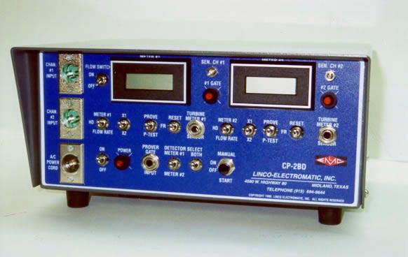
3 Version = Dec. 2, 2004 INTRODUCTION The Linco Measurement Model CP-2BD Dual Master Meter Prover Counter is a completely portable unit designed for dual meter or master meter proving, counting or totalizing applications. The unit is completely self-contained, it requires no accessory equipment other than connection to two separate transducers, such as a photo pulsers, turbine meters, tachometers, magnetic pickup or other devices which delivers a pulse or sine wave output. The LINCO MEASUREMENT Model CP-2BD consists of two independent counters, with one receiving a signal from the Master Meter and other from the meter being tested and requires that the Master Meter provide a pulse per revolution switch to gate both counters simultaneously. The incoming meter pulses are visible on two liquid crystal displays. The unit can also be applied to simultaneously prove two meters in series with a single prover detector switch input. The Model CP-2BD accepts high-speed pulses using either a balanced input for inherent noise reduction or an unbalanced input. These pulses are processed using a high sensitivity input amplifier and displayed using high-speed integrated circuits and a long life liquid crystal display. A sensitivity adjustment (VR1) is included in the unit to remove unwanted noise. For proving, internal gating circuits are provided to automatically start and stop the counter. Counts may be accumulated if desired. The CP-2BD Prover Counter will operate from either a 120 VAC power or a 12 VDC(negative ground) power source and provide a regulated voltage(+12vdc, negative ground) for operation of a photo pulser. The use of all solid state circuitry provides inherent reliability and compactness.
4 WARRANTY Linco Measurement, Inc., warrants manufactured instruments to be free from defective material or factory workmanship and agrees to repair such instruments which, under normal use and service, disclose the defect to be the fault of our manufacturing, our obligation under this warranty is limited to repairing any instrument which proves to be defective when returned within 90 days from the date of original purchase, and providing the serial number has been make know to us promptly for our records. The manufacturer does not assume any liability for direct, indirect or consequential damages whether or not arising from any defect in or the testing, repair, replacement or use of this instrument. This warranty does not apply to any of our products which have been repaired or altered by unauthorized persons or service stations in any way so as, in our judgement, to insure their stability or reliability or have had the serial number altered, defaced, or removed. Neither does this warranty apply to any of our products, which have been connected, installed or adjusted in any way other than in accordance with the instructions furnished by us. Accessories, not of our manufacture, used with this product, are not covered by this warranty. This warranty is in lieu of all other warranties expressed or implied, and no representative or person is authorized to assume for us any other liability in connection with the sale of our products. RETURNING EQUIPMENT FOR REPAIR Before returning any equipment for service, under warranty or otherwise, the factory must first be contacted giving the nature of the trouble. Instructions will then be given for either correcting the trouble or returning the equipment. Upon authorization, this equipment should be forwarded, prepaid, directly to the Linco Measurement, Inc. repair service station in you locality. All correspondence pertaining to repairs should be direct to: Linco Measurement, Inc. Attention: Electrical Repair Service P.O. Box 4096 Midland, Texas 79704
5 SECTION I SPECIFICATIONS CP-2BD Frequency Range Hz. 10 KHz. for digital pulse input 10 Hz. 10 KHz. for sine wave input. Inputs Balanced, common-mode noise rejecting Turbine Meter #1 Sensor input Stereo Jack Turbine Meter #2 Sensor input Stereo Jack Channel #1 Square Wave Photo Pulser Input - Amphenol Connector Channel #2 Square Wave Photo Pulser Input Amphenol Connector Prover Gate Input Stereo Jack Sensitivity millivolts RMS to 3,000 Hz rolling off to 90 millivolts RMS at 10,000 Hz Accuracy Plus or minus one count per side Count Capability ,999 counts per display Readouts Liquid crystal with 0.35 inch high characters Front Panel Controls Front panel selection of Count, Hold, Flow Rate, Prove, Flow Rate, P-Test, X1 - X2, Counter Reset, Detector Switch 1 2 or both, input sensitivity, and Power On-Off. Power Requirements volts AC, Hz or volts DC(negative ground), 2 amp maximum Operating Temperature - - Minus 20 degrees F to plus 158 degrees F Housing General purpose with rubber mounting feet Size (high) x 11 ¼ (wide) x 10 (deep) Weight pounds
6 SECTION III INSTALLATION OF THE CP-2BD Installation of the LINCO MEASUREMENT Model CP-2BD Dual Master Meter Prover Counter is straightforward. It s small size, light weight and ability to operate from 12 VDC power makes portable usage exceptionally convenient. Location The CP-2BD is furnished in a General Purpose Enclosure and is designed for use in a controlled environment in a non-hazardous area. The unit should not be used in an outside environment. Proper installation practice requires that the Prover Counter, transducers and connecting cables be located in an area where strong magnetic fields do not exist. Heavy motors, transformers and similar equipment should be avoided. Electrical Connections The electrical wiring required will depend on the transducers being used, the type of operation desired and the power available. Reference should be made to the drawings at the end of this manual for typical installations and connector identifications. For convenience, it may be desirable to provide two power connectors, with one wired for 120 VAC and one for 12 VDC. As shown on the drawing for TURBINE METER SENSOR pick up coils, signal connections should be run in shielded wire with the shield connected ONLY at the Prover Counter connector. Wire size of #22 gauge or larger is recommended for distances of 1,000 feet or less. For distances up to 2,500 feet #18 gauge wire should be used. CAUTION: Use care in wiring the connectors as improper connections may damage the instrument. NEVER CONNECT ANY VOLTAGE to the inputs or to the control connectors. In a typical positive displacement meter proving, using a photo pulser, cable runs between the photo pulser and the Prover Counter should be limited to 250 feet or less and the +12 volt connections should use #18 gauge wire. Loner runs will result in voltage drop in the wire, which may adversely affect the operation of the photo pulser. CAUTION: The plus 12 VDC power available at the input connector should NEVER be shorted to ground. This may result in damage to the power supply or the circuit board and will efect the warranty of the Prover Counter.
7 SECTION III CONTROLS FOR CP-2BD NOTE: Refer to the drawings in back of this manual. All controls are located on the front panel of the LINCO MEASUREMENT Model CP-2BD Dual Master Meter Prover Counter. The following is a list of the switches provided and their function starting in the upper-left of the front panel. ======================================================================= Top-Row Switches FLOW SWITCH Position On(Up) Off(Down) Meaning Both totalizers receive input pulses from the channel-1 input connector Totalizer-1 get its input from the channel-1 input connector Totalizer-2 get its input from the channel-2 input connector ======================================================================= Left-Side Switches Meter #1 / HD(Hold) / Flow Rate Switch(Left side) This switch selects the disposition of the high frequency pulses coming from either the Chan #1 Input jack or the Turbine Meter #1 Sensor jack. There would normally be 8,400 pulses on this input per barrel of fluid. Position Meter #1 HD(Hold) Flow Rate Meaning Display #1 indicates the total number of pulses since it was cleared. Freezes Display #1 at its current count. Display #1 indicates flow rate(in barrels/hour) using a K-factor of 8400 pulses/barrel X1 / X2 SWITCH(Left side) Position Meaning X1 The input pulses are multiplied by 1. X2 The input pulses are multiplied by 2(doubled). In this position the count is incremented on every positive-going and every negative-going transition of the input effectively doubling the count.
8 PROVE / FR / P-TEST SWITCH(Left side) Position Meter #1 FR P-Test Meaning An input pulse on the ProverGate Input jack starts the display counting the pulses supplied to the Chan #1 Input jack. Another input pulse on the ProverGate Input jack stops the display counting the pulses supplied to the Chan #1 Input jack. The display does not clear. Another input pulse on the ProverGate Input jack restarts the display counting the pulses supplied to the Chan #1 Input jack. The display continues counting from its previous level and does not clear. Pressing RESET will clear the display. Do this while it is not counting. The display counts the pulses supplied to the Chan #1 Input jack without regard to the pulses on the ProverGate Input jack or the 1PPR(pulse/revolution) pulses supplied to the Chan #1 Input jack. Pressing RESET will clear the display. Do this while it is not counting. This is the Photopulser Test Position. This position operates similar to the Meter #1 position except that instead of using the signal from the ProverGate Input jack the photopulser s 1PPR(pulse/revolution) signal provides start-stop control. Assume that a photopulser is connected to the Chan #1 Input jack and 1,000 pulses/revolution are coming from the photopulser. The display would start at zero(assuming that Reset had just been pressed) it would increment from 0 to The display would pause at 1000 for one revolution of the photopulser. The display would then count from 1000 to The display would pause at 2000 for one revolution of the photopulser. etc Reset Switch(Left Side) This is a momentary switch(normally up). When pressed it clears the left display to zero. =======================================================================
9 Right-Side Switches Meter #2 / HD(Hold) / Flow Rate Switch(Right side) This switch selects the disposition of the high frequency pulses coming from either the Chan #2 Input jack or the Turbine Meter #2 Sensor jack. There would normally be 8,400 pulses on this input per barrel of fluid. Note: If the Flow Switch is On(Up), then the right side is fed from the Channel #1 input jacks. Position Meter #2 HD(Hold) Flow Rate Meaning Display #2 indicates the total number of pulses since it was cleared. Freezes Display #2 at its current count. Display #2 indicates flow rate(in barrels/hour) using a K-factor of 8400 pulses/barrel X1 / X2 SWITCH(Right side) Position Meaning X1 The input pulses are multiplied by 1. X2 The input pulses are multiplied by 2(doubled). In this position the count is incremented on every positive-going and every negative-going transition of the input effectively doubling the count
10 PROVE / FR / P-TEST SWITCH(Right side) Note: If the Flow Switch is On(Up), then the right side is fed from the Channel #1 input jacks. Position Meter #2 FR(Flow Rate) P-Test Meaning An input pulse on the ProverGate Input jack starts the display counting the pulses supplied to the Chan #2 Input jack. Another input pulse on the ProverGate Input jack stops the display counting the pulses supplied to the Chan #2 Input jack. The display does not clear. Another input pulse on the ProverGate Input jack restarts the display counting the pulses supplied to the Chan #2 Input jack. The display continues counting from its previous level and does not clear. Pressing RESET will clear the display. Do this while it is not counting. The display counts the pulses supplied to the Chan #2 Input jack without regard to the pulses on the ProverGate Input jack or the 1PPR(pulse/revolution) pulses supplied to the Chan #2 Input jack. Pressing RESET will clear the display. Do this while it is not counting. This is the Photopulser Test Position. This position operates similar to the Meter #2 position except that instead of using the signal from the ProverGate Input jack the photopulser s 1PPR(pulse/revolution) signal provides start-stop control. Assume that a photopulser is connected to the Chan #2 Input jack and 1000 pulses/revolution are coming from the photopulser. The display would start at zero(assuming that Reset had just been pressed) it would increment from 0 to The display would pause at 1000 for one revolution of the photopulser. The display would then count from 1000 to The display would pause at 2000 for one revolution of the photopulser. etc Reset Switch(Right Side) This is a momentary switch(normally up). When pressed it clears the right display to zero
11 Bottom Row Switches POWER SWITCH Position ON OFF Meaning Unit is turned ON and the POWER LED is lit. Unit is OFF and the POWER LED is not lit Detector & Select Both Switches The prover travel limit switches are normally wired into the Prover Gate Input jack to the immediate left of these switches. Detector SELECT Both Position Position Meaning Meter #1(Up) OFF(Down) Routes gate input to meter #1 only. Meter #2(Up) OFF(Down) Routes gate input to meter #2 only. Doesn t matter ON(Up) Routes gate input to both meters MANUAL START(Momentary pushbutton) Position Not Pressed Pressed Meaning No effect Toggles input gating. Press to start counting. Press again to stop counting. This pushbutton switch is in parallel with the jack for the prover gate switches. This pushbutton is used to simulate a prover cycle
12 SECTION IV OPERATION OF THE CP-2BD This is the switch configuration for proving two PD meters in series in a flow line at the same time. When the connections have been made Press and release both Reset switches to zero the displays and initialize the CP-2BD. Start the prover cycle. Both Gate LED lamps will flash for each prover gate switch closure. Each display will starting counting on the first gate switch closure and stop counting on the second gate switch closure.
13 This is the switch configuration for proving two turbine meters in series in a flow line at the same time. When the connections have been made Press and release both Reset switches to zero the displays and initialize the CP-2BD. Start the prover cycle. Both Gate LED lamps will flash for each prover gate switch closure. Each display will starting counting on the first gate switch closure and stop counting on the second gate switch closure.
14 This is the switch configuration for proving a PD meter on the left side and indicating the PD meters flow on the right side. When the connections have been made Press and release both Reset switches to zero the displays and initialize the CP-2BD. Start the prover cycle. The left Gate LED lamps will flash for each prover gate switch closure. The left display will starting counting on the first gate switch closure and stop counting on the second gate switch closure. The right display will indicate flow in barrels/hour(constantly updated).
15 This is the switch configuration for proving a turbine meter on the left side and indicating the turbine meters flow on the right side. When the connections have been made Press and release both Reset switches to zero the displays and initialize the CP-2BD. Start the prover cycle. The left Gate LED lamps will flash for each prover gate switch closure. The left display will starting counting on the first gate switch closure and stop counting on the second gate switch closure. The right display will indicate flow in barrels/hour(constantly updated). Note: This is a workable configuration but the flow reading on the right side assumes 8400 pulses/barrel.
16 In this mode the operation of the photopulser(s) may be checked. Plug in the photopulser(s) and set the switches as shown above. Press the applicable Reset switch when the counter is not incrementing. Assuming 1000 pulses per revolution, the display should count from 0 to 1000, wait while displaying 1000, count from 1000 to 2000, wait while displaying 2000, etc. The Gate LEDs will blink for a very short duration.
17 SECTION V TROUBLE SHOOTING THE CP-2BD Fuses: In the event of complete loss of instrument function when operating on AC power, the fuse (F 1) or (F2) if DC powered should be checked and if defective, replaced. If all indications show that the instrument is functioning properly but no signals from a photo pulser are being received, check the fuse (F3) and if defective, replace. CAUTION: The use of a fuse other than a 3AG 2 amp size may result in damage to the instrument and voids the warranty.
18
19
LINCO MEASUREMENT MODEL CP-2B MASTER METER PROVER COUNTER INSTRUCTION MANUAL
 LINCO MEASUREMENT MODEL CP-2B MASTER METER PROVER COUNTER INSTRUCTION MANUAL ENGINEERED AUTOMATED SYSTEMS DESIGNERS ENGINEERS MANUFACTURERS SALES REPRESENTATIVES 4580 W. HWY 80 P.O. BOX 4096 MIDLAND, TEXAS
TABLE OF CONTENTS WARRANTY
 DM4000 CONTROL SERIES CONTROLS Instruction Manual Field Programmable Digital Tachometer for Rate and Time P.O. Box 10 5000 W. 106th Street Zionsville, Indiana 46077 Phone (317) 873-5211 Fax (317) 873-1105
Model 935A. Dual Tone Sender INSTRUCTION MANUAL
 Model 935A Dual Tone Sender INSTRUCTION MANUAL Monroe Electronics 100 Housel Ave Lyndonville NY 14098 800-821-6001 585-765-2254 fax 585-765-9330 monroe-electronics.com Printed in USA Copyright Monroe Electronics,
PULSE DISTRIBUTION AMPLIFIER OPERATING MANUAL
 SPECTRADYNAMICS, INC PD5-RM-B PULSE DISTRIBUTION AMPLIFIER OPERATING MANUAL SPECTRADYNAMICS, INC 1849 Cherry St. Unit 2. Louisville, CO 80027 Phone: (303) 665-1852 Fax: (303) 604-6088 www.spectradynamics.com
Model 7000 Low Noise Differential Preamplifier
 Model 7000 Low Noise Differential Preamplifier Operating Manual Service and Warranty Krohn-Hite Instruments are designed and manufactured in accordance with sound engineering practices and should give
INSTRUCTION MANUAL LKG 601 Electrical Safety Analyzer
 INSTRUCTION MANUAL LKG 601 Electrical Safety Analyzer 110 Toledo Street Farmingdale, NY 11735 USA http://www.netech.org 510-USER-Manual Rev3 10/29/2007 Dear User, We appreciate your purchase of the LKG
PDB4. Four Channel Passive Direct Box USER'S GUIDE
 PDB4 Four Channel Passive Direct Box USER'S GUIDE IMPORTANT SAFETY INSTRUCTIONS - READ FIRST This symbol, wherever it appears, alerts you to important operating and maintenance instructions in the accompanying
Frequency Calibrator with Totalizer
 Frequency Calibrator with Totalizer Model 942 0.001% accuracy Locked to high stability crystal Six real world ranges 1 to 20000 counts-per-hour to 2000.0 counts-per-minute 0.01 to 999.99 Hz to 9999.9 Hz
TRANSDUCER IN-LINE AMPLIFIER
 TRANSDUCER IN-LINE Bi-Polar Model AMPLIFIER 2080 Arlingate Lane, Columbus, Ohio 43228 (614) 850-5000 Sensotec, Inc. 2080 Arlingate Lane Columbus, Ohio 43228 Copyright 1995 by Sensotec, Inc. all rights
TRANSDUCER IN-LINE AMPLIFIER
 TRANSDUCER IN-LINE Voltage Model AMPLIFIER 2080 Arlingate, Columbus, Ohio 43228, (614) 850-5000 Sensotec, Inc. 2080 Arlingate Lane Columbus, Ohio 43228 Copyright 1995 by Sensotec, Inc. all rights reserved
Fits Tiger 320 Series UNIVERSAL FREQ/COUNTER INPUT MODULE
 Fits Tiger 320 Series UNIVERSAL /ER INPUT MODULE Sensor. Magnetic, Namur, Source, Sink. De-coupling. 0.02 Hz high pass filter. Signal Type., (mv) or digital logic. Input Connector. Freq. Input (CH) Up/Down
SL300 Snow Depth Sensor USL300 SNOW DEPTH SENSOR. Revision User Manual
 USL300 SNOW DEPTH SENSOR Revision 1.1.2 User Manual 1 Table of Contents 1. Introduction... 3 2. Operation... 3 2.1. Electrostatic Transducer... 4 2.2. SL300 Analog Board... 4 2.3. SL300 Digital Circuit
MZ2 HEADPHONE AMPLIFIER, PREAMP, & STEREO AMPLIFIER USER GUIDE
 MZ2 HEADPHONE AMPLIFIER, PREAMP, & STEREO AMPLIFIER USER GUIDE Linear Tube Audio Takoma Park, MD, USA WARNING: For safety, the cover of this amplifier should be secured at all times. DC voltages as high
Classic Series Public Address Amplifiers C10 & C20 Models
 Classic Series Public Address Amplifiers C10 & C20 Models Installation and Use Manual 2009 Bogen Communications, Inc. All rights reserved. Specifications subject to change without notice. 54-5978-01B 0901
INSTALLATION AND MAINTENANCE MANUAL FOR GROUND MONITOR GM-250 COPYRIGHT 1983 AMERICAN MINE RESEARCH, INC.
 INSTALLATION AND MAINTENANCE MANUAL FOR GROUND MONITOR GM-250 COPYRIGHT 1983 AMERICAN MINE RESEARCH, INC. MANUAL PART NUMBER 180-0036 ORIGINAL: 1-17-83 REVISION: B (8-26-86) NOT TO BE CHANGED WITHOUT MSHA
CALIBRATED IMPULSE GENERATOR MODEL CIG khz 1 GHz
 INSTRUCTION MANUAL CALIBRATED IMPULSE GENERATOR MODEL CIG-25 10 khz 1 GHz INSTRUCTION MANUAL THIS INSTRUCTION MANUAL AND ITS ASSOCIATED INFORMATION IS PROPRIETARY. UNAUTHORIZED REPRODUCTION IS FORBIDDEN.
Classic Series Public Address Amplifiers C10 & C20 Models
 Classic Series Public Address Amplifiers C10 & C20 Models Installation and Use Manual 2009 Bogen Communications, Inc. All rights reserved. Specifications subject to change without notice. 54-5978-01C 1106
INSTALLATION & OPERATION MANUAL
 INSTALLATION & OPERATION MANUAL AN25 Totalizer/ Rate Indicator DOC#: MN-AN25.doc Sponsler Co., Inc. AN25 Totalizer/Rate Indicator pg. 2 DOC#: MN-AN25 SPECIFICATIONS Temperature: Operating 0 to 70 C Storage
2001A. 200KHz Function Generator Instruction Manual. 99 Washington Street Melrose, MA Phone Toll Free
 2001A 200KHz Function Generator Instruction Manual 99 Washington Street Melrose, MA 02176 Phone 781-665-1400 Toll Free 1-800-517-8431 Visit us at www.testequipmentdepot.com WARRANTY Global Specialties
K-FACTOR SCALER B & B
 K-FACTOR SCALER B220-880 & B220-881 INSTALLATION & INSTRUCTION MANUAL 8635 Washington Ave. Racine, Wisconsin 53406 Technical Toll-Free: 877.722.4631 Sales Toll-Free: 800.235.1638 Phone: 262.639.6770 Fax:
ZOTL40 Mk.II POWER AMPLIFIER USER GUIDE. Linear Tube Audio Takoma Park, MD, USA
 ZOTL40 Mk.II POWER AMPLIFIER USER GUIDE Linear Tube Audio Takoma Park, MD, USA WARNING: For safety, the cover of this amplifier should be secured at all times. DC voltages as high as 1000V and peak AC
Process Calibrator. TechChek 820
 Process Calibrator TechChek 80 CONTENTS GENERAL... TURN ON... CONNECTIONS... TILT STAND...4 CHANGING BATTERIES...4 RESTORING DEFAULT SETTINGS... CONFIGURING TEMPERATURE SCALES... ENABLING AUTO-OFF... SELECTING
PCO-7114 Laser Diode Driver Module Operation Manual
 PCO-7114 Laser Diode Driver Module Operation Manual Directed Energy, Inc. 1609 Oakridge Dr., Suite 100, Fort Collins, CO 80525, (970) 493-1901 sales@ixyscolorado.com www.ixyscolorado.com Manual Document
Owner s Manual DKW-3 HT. Wireless VHF Microphone System
 Owner s Manual DKW-3 HT Wireless VHF Microphone System Contents Introduction... 2 System Features... 2 Operation... 3 Specifications... 5 Service Information... 6 Warranty... 7 Introduction Thank you for
Safety. This symbol, adjacent to a terminal, indicates that, under normal use, hazardous voltages may be present.
 9305 Safety International Safety Symbols This symbol, adjacent to another symbol or terminal, indicates the user must refer to the manual for further information. This symbol, adjacent to a terminal, indicates
SDI SPECTRADYNAMICS, INC. HIGH PERFORMANCE DISTRIBUTION AMPLIFIER OPERATING MANUAL
 SPECTRADYNAMICS, INC. HIGH PERFORMANCE DISTRIBUTION AMPLIFIER HPDA15RMC OPERATING MANUAL SPECTRADYNAMICS, INC 1849 Cherry St. Unit 2. Louisville, CO 80027 Phone: (303) 6651852 Fax: (303) 6046088 www.spectradynamics.com
Frequency Calibrator with Totalizer
 99 Washington Street Melrose, MA 02176 Phone 781-665-1400 Toll Free 1-800-517-8431 Frequency Calibrator with Totalizer Model 942 0.001% accuracy Locked to high stability crystal Six real world ranges 1
SDI SPECTRADYNAMICS, INC. LOW NOISE FREQUENCY REFERENCE OPERATING MANUAL
 SPECTRADYNAMICS, INC. LOW NOISE FREQUENCY REFERENCE LNFR-100E OPERATING MANUAL SPECTRADYNAMICS, INC 1849 Cherry St. Unit 2. Louisville, CO 80027 Phone: (303) 665-1852 Fax: (303) 604-6088 www.spectradynamics.com
HTA125A/250A. Power Amplifiers. Installation & Use Manual
 HTA125A/250A Power Amplifiers Installation & Use Manual Specifications subject to change without notice. 2010 Bogen Communications, Inc. All rights reserved. 54-5832-04B 1011 NOTICE: Every effort was made
WireMaster Coax BNC PN: Rev C 2/13
 WireMaster Coax BNC Instruction Manual PN: 3274 84-868 Rev C 2/13 Table of Contents Features...... 2 Introduction... 3 Warnings and Cautions... 3 Specifications...4 Typical Cable/Wire Resistances...5 Control
PIECAL Model 541 Frequency Calibrator with Totalizer Operating Instructions
 PIECAL Model 541 Frequency Calibrator with Totalizer Operating Instructions Easy to use With the Model 541 you can check & calibrate all your frequency instruments and measure flow sensors. Take it into
DA560D COMPACT SERIES. INSTALLATION / OWNER'S MANUAL Mobile Power Amplifiers
 DA560D COMPACT SERIES INSTALLATION / OWNER'S MANUAL Mobile Power Amplifiers Preparation Please read entire manual before installation. Due to the technical nature of amplifiers, it is highly recommended
DUAL LEVELAR. Two Channel Tube Compressor/Leveling Amplifier
 DUAL LEVELAR Two Channel Tube Compressor/Leveling Amplifier USER S GUIDE Introduction Thank you for purchasing the Dual Levelar and congratulations! You now own one of the most sophisticated pieces of
Series 3000 Model R-107A
 Series 3000 Model R-107A DUAL TONE SENDER INSTRUCTION MANUAL Monroe Electronics 100 Housel Ave Lyndonville NY 14098 800-821-6001 585-765-2254 fax 585-765-9330 monroe-electronics.com Printed in USA Copyright
Programmable K-Factor Scaler B and Programming Software Kit B
 Programmable K-Factor Scaler B220-885 and Programming Software Kit B220-900 INSTALLATION & INSTRUCTION MANUAL 8635 Washington Avenue Racine, Wisconsin 53406 Toll Free: 800.235.1638 Phone: 262.639.6770
BC145 SIGNAL ISOLATOR BOARD
 BC145 SIGNAL ISOLATOR BOARD 4/17 Installation & Operating Manual MN1373 Any trademarks used in this manual are the property of their respective owners. Important: Be sure to check www.baldor.com to download
SIR, RADAN and UtilityScan are registered trademarks of Geophysical Survey Systems, Inc..
 Copyright 2001-2017 Geophysical Survey Systems, Inc. All rights reserved including the right of reproduction in whole or in part in any form Published by Geophysical Survey Systems, Inc. 40 Simon Street
Model Hz to 10MHz Precision Phasemeter. Operating Manual
 Model 6610 1Hz to 10MHz Precision Phasemeter Operating Manual Service and Warranty Krohn-Hite Instruments are designed and manufactured in accordance with sound engineering practices and should give long
DA604D DA954D DA501D DA801D COMPACT SERIES. INSTALLATION / OWNER'S MANUAL Mobile Power Amplifiers
 DA604D DA954D DA501D DA801D COMPACT SERIES INSTALLATION / OWNER'S MANUAL Mobile Power Amplifiers Preparation Please read entire manual before installation. Due to the technical nature of amplifiers, it
KeyPre KP6 - Electronic Instrument Preamplifier
 ! USE ONLY WITH 250V FUSE KeyPre KP6 - Electronic Instrument Preamplifier USER S GUIDE 0 10dB 0 10dB 0 10dB 0 10dB 0dB 10dB 0 10dB AVEDIS AUDIO E L E C T R O N I C S AC INPUT 100-240VAC 50/60 Hz 1.1" 1.225"
User s Guide Instructions for Installation and Operation
 User s Guide Instructions for Installation and Operation 2.4 GHZ SPREAD SPECTRUM REMOTE CONTROLS Keyfob Transmitters Models KTX24SS1 KTXW24SS3 KTX24SS2 KTX24SS3 Wall Mount Models NTX24SS1 NTX24SS2 Remote
Synthesized Base Station Transmitter
 BST-75 OPERATOR S MANUAL (72-76 MHz) Synthesized Base Station Transmitter 357 West 2700 South Salt Lake City, Utah 84115 Phone: (800) 496-3463 Fax: (801) 484-6906 www.comtek.com TABLE OF CONTENTS Introduction...
NV-P2100. Audio Amplifier Owner s Manual
 NV-P21 Audio Amplifier Owner s Manual NV-P21 Audio Amplifier Congratulations on your purchase of the NuVo P21 audio amplifier. The P21 brings advanced technology of superior home sound together with
Harris IRT Enterprises Multi-Channel Digital Resistance Tester Model XR
 Harris IRT Enterprises Multi-Channel Digital Resistance Tester Model 6012-06XR Specifications & Dimensions 2 Theory of Operation 3 System Block Diagram 4 Operator Controls & Connectors 5 Test Connections
301 & 601 Mic/Line Mixers Operation Manual
 301 & 601 Mic/Line Mixers Operation Manual Biamp Systems 9300 S.W. Gemini Drive Beaverton, OR 97008 USA +1.503.641.7287 www.biamp.com 301 & 601 TABLE OF CONTENTS Introduction Front Panel Rear Panel Remote
Owner s Manual.
 P Z R 6 0 0 A m p l i f i e r P Z R 1 0 0 0 A m p l i f i e r Owner s Manual www.pyleaudio.com Your New Pyle Pro PZR series P.A. Amplifier gives you the power and versatility you need in a professional
HQ-31 HQ-15 USER S GUIDE SINGLE CHANNEL 31 BAND 1/3 OCTAVE GRAPHIC EQUALIZER DUAL CHANNEL 15 BAND 2/3 OCTAVE GRAPHIC EQUALIZER
 HQ-31 SINGLE CHANNEL 31 BAND 1/3 OCTAVE GRAPHIC EQUALIZER HQ-15 DUAL CHANNEL 15 BAND 2/3 OCTAVE GRAPHIC EQUALIZER USER S GUIDE GENERAL INFORMATION SINGLE CHANNEL 31 BAND 1/3 OCTAVE GRAPHIC EQUALIZER WITH
MIRAGE BD-38-G DUAL BAND POWER AMPLIFIER
 MIRAGE BD-38-G DUAL BAND POWER AMPLIFIER MIRAGE BD-38-G Dual Band Amplifier INTRODUCTION: The Mirage BD-38-G is a 80/60 watt dual band power amplifier for use with today's dual band handie talkies operating
K-Factor Scaler F5140 and Programming Kit F5141 Installation & Operating Instructions
 F5140 and Programming Kit F5141 8635 Washington Avenue Racine, WI 53406 USA Tel: 800-433-5263 or 262-639-6770 Fax: 800-245-3569 or 262-639-2267 E-Mail: flo-techsales@racinefed.com www.flo-tech.com TABLE
INSTRUCTION MANUAL LKG
 INSTRUCTION MANUAL LKG 610 Electrical Safety Analyzer With 10 ECG Connectors 110 Toledo Street Farmingdale, NY 11735 USA Homepage: www.netech.org Dear User, We appreciate your purchase of the LKG 610 Electrical
441 DUAL CHANNEL 15 BAND 2/3 OCTAVE GRAPHIC EQUALIZER 451 SINGLE CHANNEL 31 BAND 1/3 OCTAVE GRAPHIC EQUALIZER
 441 DUAL CHANNEL 15 BAND 2/3 OCTAVE GRAPHIC EQUALIZER 451 SINGLE CHANNEL 31 BAND 1/3 OCTAVE GRAPHIC EQUALIZER 455 DUAL CHANNEL 31 BAND 1/3 OCTAVE GRAPHIC EQUALIZER The new ART 400 Series of Precision Graphic
MODEL FS-4 INSTRUCTION MANUAL R.L. DRAKE COMPANY, MIAMISBURG, OHIO, U.S.A.
 MODEL FS-4 F R E Q U E N C Y S Y N T H E S I Z E R INSTRUCTION MANUAL R.L. DRAKE COMPANY, MIAMISBURG, OHIO, U.S.A. LIMITED WARRANTY R. L. DRAKE COMPANY warrants to the original purchaser that this product
KX120.2 / KX150.2 / KX200.2
 KX120.2 / KX150.2 / KX200.2 Congratulations! You have just purchased the latest in amplifier technology to carry the famous KICKER name. Your KICKER KX series amplifier is designed and built to give you
DA6002D-DA10004D. INSTALLATION / OWNER'S MANUAL Mobile Power Amplifiers
 DA6002D-DA10004D INSTALLATION / OWNER'S MANUAL Mobile Power Amplifiers Preparation Please read entire manual before installation. Due to the technical nature of amplifiers, it is highly recommended that
Model 3210C. 100 Ampere AC Current Standard. Operating Manual
 Model 3210C 100 Ampere AC Current Standard Operating Manual This page intentionally left blank. 3210C OPERATORS MANUAL Serial No. Win-man\3210C.wpd This page intentionally left blank. 3210C OPERATORS MANUAL
COOLED InGaAS DETECTOR HEAD MODEL 71887
 ORIEL PRODUCT LINE 150 Long Beach Boulevard Stratford, CT 06615 Phone (203) 377-8282 (800) 714-5393 Fax: (203) 378-2457 E-MAIL: oriel.sales@newport.com MODEL 71887 USER MANUAL Please read these instructions
CHECK LINE INSTRUMENTS. ! Tolerates a wide variation of voltages. ! Immune to electrically noisy environments.
 Panel Mount Tachometer Model DT-5TG (VDC) CHECK LINE INSTRUMENTS ELECTROMATIC E Q U I P M E N T C O., I N C. 600 Oakland Ave., Cedarhurst, NY 11516 U.S.A. TEL: 516-295-4300 FAX: 516-295-4399 Instruction
Model 9305 Fast Preamplifier Operating and Service Manual
 Model 9305 Fast Preamplifier Operating and Service Manual This manual applies to instruments marked Rev 03" on rear panel. Printed in U.S.A. ORTEC Part No.605540 1202 Manual Revision B Advanced Measurement
MLA High Performance Microstepping Driver. User s Guide E. Landon Drive Anaheim, CA
 MLA10641 High Performance Microstepping Driver User s Guide A N A H E I M A U T O M A T I O N 4985 E. Landon Drive Anaheim, CA 92807 e-mail: info@anaheimautomation.com (714) 992-6990 fax: (714) 992-0471
OPERATION & SERVICE MANUAL FOR FC 110 AC POWER SOURCE
 OPERATION & SERVICE MANUAL FOR FC 100 SERIES AC POWER SOURCE FC 110 AC POWER SOURCE VERSION 1.3, April 2001. copyright reserved. DWG No. FC00001 TABLE OF CONTENTS CHAPTER 1 INTRODUCTION... 1 1.1 GENERAL...
TRIAXIAL FLUXGATE MAGNETOMETER OWNER'S MANUAL
 TRIAXIAL FLUXGATE MAGNETOMETER OWNER'S MANUAL PART NUMBER: FGM-301 WATSON INDUSTRIES, INC. 3041 MELBY ROAD EAU CLAIRE, WI 54703 Phone: (715) 839-0628 FAX: (715) 839-8248 email: support@watson-gyro.com
WARRANTY We at DigiTech are very proud of our products and back-up each one we sell with the following warranty:
 Owner s Manual WARRANTY We at DigiTech are very proud of our products and back-up each one we sell with the following warranty: 1. Please register online at digitech.com within ten days of purchase to
Model MV106J/MV116J. ±10nVdc to ±11Vdc Precision DC Voltage Standard Source. Operating Manual
 Model MV106J/MV116J ±10nVdc to ±11Vdc Precision DC Voltage Standard Source Operating Manual This page intentionally left blank. MV 106 & MV116 OPERATORS MANUAL Serial No. Win-man\mvman.wpd This page intentionally
Owner s Manual. DKW-Duo. Dual Wireless Microphone System
 Owner s Manual DKW-Duo Dual Wireless Microphone System Contents Introduction... 2 System Features... 2 Operation.... 3 Specifications... 5 Service Information,. Miscellaneous Tips & Troubleshooting...
XPR522 XPR540. XPR SERIES INSTALLATION / OWNER'S MANUAL Mobile Power Amplifiers
 XPR522 XPR540 XPR SERIES INSTALLATION / OWNER'S MANUAL Mobile Power Amplifiers Preparation Please read entire manual before installation. Due to the technical nature of amplifiers, it is highly recommended
Power-Tronics, Inc. Electronic Voltage Regulators and Static Exciters P.O. Box , Kerrville, Texas 78029
 Power-Tronics, Inc. Electronic Voltage Regulators and Static Exciters P.O. Box 291509, Kerrville, Texas 78029 Phone: 830.895.4700 Fax: 830.895.4703 Email: pwrtron@power-tronics.com Web: www.power-tronics.com
MODEL UBP-10 UNIVERSAL IN-LINE TRANSDUCER AMPLIFIER BI-POLAR SUPPLY, 0-10 VOLT OUTPUT
 MODEL UBP-10 UNIVERSAL IN-LINE TRANSDUCER AMPLIFIER BI-POLAR SUPPLY, 0-10 VOLT OUTPUT 2080 Arlingate Lane, Columbus, Ohio 43228 (614) 850-5000 Sensotec, Inc. 2080 Arlingate Lane Columbus, Ohio 43228 Copyright
XIA3145 INSTALLATION/OWNER S MANUAL 2/1-Channel Mobile Power Amplifier
 XIA3145 INSTALLATION/OWNER S MANUAL 2/1-Channel Mobile Power Amplifier XIA3145 INSTALLATION Preparation Please read entire manual before installation. Due to the technical nature of amplifiers, it is highly
JMAA-1800HR15. Installation and Operation Instructions. 180w Performance Series Amplifier Kit For Harley RoadGlide/ Ultra
 180w Performance Series Amplifier Kit For 2015-2018 Harley RoadGlide/ Ultra # JMAA-1800HR15 2017 J&M Corporation. All rights reserved. 9/17 Installation and Operation Instructions Product Description This
Model 8140VT VERSATAP INSTALLATION AND OPERATION MANUAL
 VERSATAP INSTALLATION AND OPERATION MANUAL 95 Methodist Hill Drive Rochester, NY 14623 Phone: US +1.585.321.5800 Fax: US +1.585.321.5219 www.spectracomcorp.com Part Number 8147-5000-0050 Manual Revision
XPA2100 XPA4100 XPA6100. XPA SERIES INSTALLATION/OWNER S MANUAL Mobile Power Amplifiers
 XPA2100 XPA4100 XPA6100 XPA SERIES INSTALLATION/OWNER S MANUAL Mobile Power Amplifiers XPA SERIES INSTALLATION Preparation Please read entire manual before installation. Due to the technical nature of
MBC Bipolar Microstep Driver. User s Guide E. Landon Drive Anaheim, CA
 MBC10641 Bipolar Microstep Driver User s Guide A N A H E I M A U T O M A T I O N 4985 E. Landon Drive Anaheim, CA 92807 e-mail: info@anaheimautomation.com (714) 992-6990 fax: (714) 992-0471 website: www.anaheimautomation.com
INSTRUCTIONS PS2500 POWER SUPPLY
 INSTRUCTIONS PS2500 POWER SUPPLY The Hoefer PS 2500 Power Supply will furnished power to Constant Voltage or Constant Power modes of operation. It will accurately supply 0-2500 volts, 0-300 ma or 0-375
F Series SINGLE-PHASE DIGITAL SWITCHBOARD MONITORS FVA, FVD, FAA, FAD, FF, FT MODELS
 F Series SINGE-PHASE DIGITA SWITCHBOARD MONITORS FVA, FVD, FAA, FAD, FF, FT MODES User's Manual Revision 1.9 September 22, 2017 e Electro Industries/GaugeTech 1800 Shames Drive Westbury, New York 11590
Glass Electrode Meter
 Glass Electrode Meter INSTRUCTION MANUAL FOR Glass Electrode R/C Meter MODEL 2700 Serial # Date PO Box 850 Carlsborg, WA 98324 U.S.A. 360-683-8300 800-426-1306 FAX: 360-683-3525 http://www.a-msystems.com
Introduction. Specifications. Features. Controls. Model 103
 Index Page # Model 103 2 Introduction 2 Specifications 2 Features 2 Controls 2 Hints and Tips 3 Input Sensitivity (typical) 3 RF Signal Strength Bargraph 3 Frequency Display Resolution 3 Model 104 4 Introduction
Model CC4041. CC Series Amplifier. Installation and Use Manual
 BASS 0 TREBLE 0-12 +12-12 +12 INPUT 1 INPUT 2 INPUT 3 INPUT 4 PEAK SIGNAL POWER POWER CC Series Amplifier Model CC4041 Installation and Use Manual 2012 Bogen Communications, Inc. All rights reserved. Specifications
Owner s Manual DKW-3 GT. Wireless VHF Instrument System
 Owner s Manual DKW-3 GT Wireless VHF Instrument System Contents Introduction... 2 System Features... 2 Operation... 3 Specifications... 6 Service Information... 6 Warranty... 7 Introduction Thank you for
MICROTOOLS MICRONETBLINK KIT
 MICROTOOLS MICRONETBLINK KIT MicroNetBlink TM MicroProbe TM User Guide Manuel Utilisateur Benutzer Handbuch Manuale per l'utente Guía del Usuario Manual do Utilizador 2947-4511-01 Rev. 01 11/01 2001 Fluke
CT-2 and CT-3 Channel Taggers OPERATION MANUAL
 CT-2 and CT-3 Channel Taggers OPERATION MANUAL Trilithic Company Profile Trilithic is a privately held manufacturer founded in 1986 as an engineering and assembly company that built and designed customer-directed
Model 9302 Amplifier-Discriminator Operating and Service Manual
 Model 9302 Amplifier-Discriminator Operating and Service Manual Printed in U.S.A. ORTEC Part No. 733690 1202 Manual Revision C Advanced Measurement Technology, Inc. a/k/a/ ORTEC, a subsidiary of AMETEK,
WARRANTY We at DigiTech are very proud of our products and back-up each one we sell with the following warranty:
 Owner s Manual WARRANTY We at DigiTech are very proud of our products and back-up each one we sell with the following warranty: 1. Please register online at digitech.com within ten days of purchase to
PARALLEL MULTI-AMP KIT for 7200 Series AMPLIFIERS INSTRUCTION SHEET
 2 5 0 7 W a r r e n S t r e e t, E l k h a r t, I N 4 6 5 1 6 U S A 5 7 4. 2 9 5. 9 4 9 5 w w w. A E T e c h r o n. c o m PARALLEL MULTI-AMP KIT for 7200 Series AMPLIFIERS INSTRUCTION SHEET Kit Contents:
FLOW SWITCH 600 Series Velocity Flow Sensor. Instruction Manual
 SWITCH 600 Series Velocity Flow Sensor Instruction Manual Ultrasonic Velocity Sensor using Doppler Technology Model: FS-600 Manual Release Date: November, 2009 ECHO Process Instrumentation, Inc. CONTENTS
INSTRUMENTS, INC. Model 2960AX Disciplined Quartz Frequency Standard 2960AX. Section Page Contents
 INSTRUMENTS, INC. Model 2960AX Disciplined Quartz Frequency Standard 2960AX Section Page Contents 1.0............................. 2......................... Description 2.0.............................
USER GUIDE PLENUM-RATED AUDIO AMPLIFIER
 USER GUIDE PLENUM-RATED AUDIO AMPLIFIER Model: 40100 1 Table of Contents TABLE OF CONTENTS Introduction... 2 Features... 3 System Requirements... 4 Package Contents... 5 Device Overview... 6 Device Installation...
WARRANTY. Long Range Systems, LLC, 20 Canal St, Suite 4N, Franklin, NH 03235
 WARRANTY Long Range Systems, Inc. warrants the trap release product against any defects that are due to faulty material or workmanship for a one-year period after the original date of consumer purchase.
JMAA-3600HR16-UL. Installation and Operation Instructions. Performance Series 360w RMS 4-Channel Amplifier Kit For Harley RoadGlide Ultra
 Performance Series 360w RMS 4-Channel Amplifier Kit For 2016-2018 Harley RoadGlide Ultra # JMAA-3600HR16-UL 2017 J&M Corporation. All rights reserved. 9/17 Installation and Operation Instructions Product
A Channel Amplifier
 Installation Manual A2150 2 Channel Amplifier Table of Contents Installation Requirements and Recommendations 1 What s included 1 Speaker Wire Recommendations 1 Setup 2 Rack Mounting 2 Individually Protected
DL102 Counter Loop Amplifier
 DL102 Counter Loop Amplifier USER MANUAL MAN 234A Contents Overview...3 System Includes...3 Maintenance and Recycling Instructions...3 Safety Information...4 Quick Setup...5 Setup...6 Loop Amplifier...6
INSTRUCTION MANUAL For LINE IMPEDANCE STABILIZATION NETWORK. Model LI khz to 10 MHz
 Page 1 of 10 INSTRUCTION MANUAL For LINE IMPEDANCE STABILIZATION NETWORK Model LI-4100 10 khz to 10 MHz Page 2 of 10 Table of Contents 1.0 Introduction... 3 2.0 Product Description... 4 3.0 Product Specifications...
34134A AC/DC DMM Current Probe. User s Guide. Publication number April 2009
 User s Guide Publication number 34134-90001 April 2009 For Safety information, Warranties, Regulatory information, and publishing information, see the pages at the back of this book. Copyright Agilent
Operating Instruction Manual ELECTRONIC MUSIC AMPLIFICATION SYSTEM. Model KD-1. Toa Electric Co., Ltd. KOBE, JAPAN
 Operating Instruction Manual ELECTRONIC MUSIC AMPLIFICATION SYSTEM Model KD-1 Toa Electric Co., Ltd. KOBE, JAPAN Contents Precautions... 1 General Description... 2 Features... 2 Front Panel: Names of components
WARRANTY We at DigiTech are very proud of our products and back-up each one we sell with the following warranty:
 Owner s Manual WARRANTY We at DigiTech are very proud of our products and back-up each one we sell with the following warranty: 1. Please register online at digitech.com within ten days of purchase to
INSTALATION, OPERATION & MAINTENANCE MANUAL. PA-1001A Series SIGNAL CONDITIONER & CONVERTORS
 INSTALATION, OPERATION & MAINTENANCE MANUAL FOR PA-1001A Series SIGNAL CONDITIONER & CONVERTORS PA1001A 7/02 Page 1 of 11 SIGNAL CONDITIONER & CONVERTERS PA1001A Series INTRODUCTION: The PA1001A series
Directed Energy, Inc Oakridge Dr., Suite 100, Fort Collins, CO
 PCO-7121 Laser Diode Driver Module Operation Manual Directed Energy, Inc. 1609 Oakridge Dr., Suite 100, Fort Collins, CO 80525 sales@ixyscolorado.com www.ixyscolorado.com Contents Contents... 3 Safety...
INSTRUCTION MANUAL. March 11, 2003, Revision 3
 INSTRUCTION MANUAL Model 701A Stimulator March 11, 2003, Revision 3 Copyright 2003 Aurora Scientific Inc. Aurora Scientific Inc. 360 Industrial Parkway S., Unit 4 Aurora, Ontario, Canada L4G 3V7 Tel: 1-905-727-5161
LT3000 ULTRASONIC LEVEL TRANSMITTER
 LT3000 ULTRASONIC LEVEL TRANSMITTER Owner s Manual Specifications Installation Calibration Troubleshooting Warranty Drawings Distributed By: iprocessmart.com 14262 Doolittle Drive San Leandro, CA 94577
POWER SERIES Plus. Volt / Amp / Hertz. Digital Switchboard Meter. User s Manual IM2493VAF-3
 POWER SERIES Plus Volt / Amp / Hertz Digital Switchboard Meter User s Manual General Description The POWER SERIES Plus digital switchboard meters incorporate the latest DSP microprocessor technology. Careful
Worldwide Manufacturer of Gas Detection Solutions. Transmitter EC 23. Operation Manual
 Worldwide Manufacturer of Gas Detection Solutions Transmitter EC 23 Operation Manual Table of Contents For Your Safety...4 General Description...4 Electrical Connections...5 Zero Point Adjustment...5