GENERALS ELECTRIC INSTRUCTIONS POWER SYSTEMS MANAGEMENT DEPARTMENT PHILADELPHIA, PA. GEK Insert Booklet GEK RESTRAINT CIRCUITS
|
|
|
- Maria Dennis
- 5 years ago
- Views:
Transcription


1 PHILADELPHIA, PA. TYPE STD29C GENERALS ELECTRIC POWER SYSTEMS MANAGEMENT DEPARTMENT 6 RESTRAINT CIRCUITS WITH PERCENTAGE AND HARMONIC RESTRAiNT TRANSFORMER DIFFERENTIAL RELAY GEK Insert Booklet GEK INSTRUCTIONS
2

3 3 the harmonic restraint is provided by the second harmonic only so that the normal odd harmonic flowing in Figure 1 illustrates the outline and panel drilling for the STD29C(-)D drawout case. Figure 2 illustrates the internal connections diagram for the STD29C. be referred to the General Electric Company. or should particular probl.ms arise which ore not covered sufficiently for the purchaser s purposes, the matter should This matter is discussed in more detail in the attached instruction book under the paragraph contingency to be met in connection with installation, operation or maintenance. Should further information be desired These instructions do not purport to cover all details or variations in equipment nor to provide for every possible Harmonic Current Restraint. 7.3 the protection of high voltage rectifier transformers. This relay is similar to the STD15C, except that Figure 3 illustrates the external wiring diagram for the STD29C relay. Figure 4 illustrates the test circuit for the STO relays. Note polarity when connecting DC sources. by-pass current levels are required: % SECOND HARMONIC =.2l2Idc X 100 component, and the by-pass current. straint for the 15% calibration, no attempt should be made to obtain a more precise setting. A tolerance of + 1% is acceptable, thus if the relay operated within 14 - harmonic current re 16% S2 switch closed to position A. at 4.0 amps and the ii (current into relay) at 8.1 amps per the test circuit illustrated in Figure 4 with since the harmonic restraint can be set at 15% by adjusting R2 such may be checked by adjusting the Id-c TESTING INSTRUCTIONS restraint may be set at 15% minimum. setting calculation as outlined for the STD15, except the STD29 relay is so designed that the harmonic by precisely tuned filters. However, the change in harmonic restraint does not change the application or The STD29C relay is a single phase harmonic restrained transformer percentage ditferential relay for The STD29C relay may be tested per the instructions in the attached instruction book. In addition, The following expression shows the relationship between the percent second harmonic, the d c AND APPLICATION DESCRIPTION ot the two form the instructions for the Type STD29C. These instructions are a supplement to instruction book GEK 45307, which is attached. The combination INTRODUCTION WITH PERCENTAGE AND HARMONIC RESTRAINT 14% 16% 15% TRANSFORMER DIFFERENTIAL RELAY TYPE STOZOC a rectifier transformer will not reduce the relay sensitivity. This harmonic selection is accomplished By setting the Idc at 4.0 amps, and solving for the % second harmonic for 14 16%, the following GEK-45316
![GEK-45316 PANEL 1)CAT ION NUNBE]{ThG OF STUDS (FRONT VIEW) ii 13 15 17 19N jcdoo 0 00000](/docs-images/90/101829175/images/4-1.jpg "12 11. 16 18 20 1357 9 00000 3 -DR.")

4 GEK PANEL 1)CAT ION NUNBE]{ThG OF STUDS (FRONT VIEW) ii N jcdoo DR. 20 MOLES DRI L VIEw S)iOWThG ASSXBLY OF hardware FOR STJRFM! ffg ON STEEL PANElS :3 PANEL IiRILLThG 4I FLU1 MTG FIb. 1 (0178A7336-2) Outline And Panel Drilling Dimensions For The Large, Double Ended, Deep (L2D) Case Of The STD29C Relay 4
 Internal Connections")


 CURRENT EF")
5 5 Relay FIG. 2 (0257A5035-O) Internal Connections Diagram For The STD29C B 200n- F TO A$Y RESTR. TRANSF. D. C. T. 0 T.C.T. ThROUGH CURRENT DI FFEREHTI AL NO. TO TERM. RD. RECTIFIER LEAD DIFFEREIITIAI. * LEGEND SHORT FINGER CURRENT TRANSF. SI TI St 20 ( DC) 13 (-IDC) GEK l1r Tl NIIMRFR TRANSFORMER THRt) CURRENT EF 500-n O8v I25V
 Typical Lxternal Connections")
6 GEK U FIG. 3 (0165B2569-I) Typical Lxternal Connections Diagram For The STD29C Relay 6
 Test Connections Diagram For The STD29C Relay")
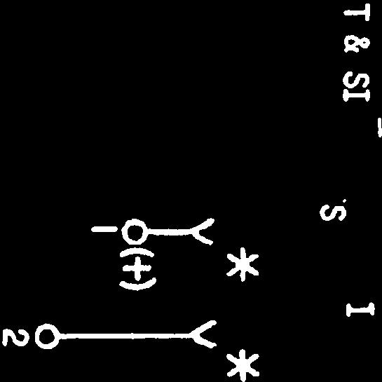
7 7 PIG. 4 (0246A2293 1) Test Connections Diagram For The STD29C Relay TEST CIRCUIT FOR STD29 RELAYS TEST PLUG XLA12A GEK-45316
8 GE Power Management 215 Anderson Avenue Markham, Ontario Canada L6E 1B3 Tel: (905) Fax: (905)


9 GEK-45307K INSTRUCTIONS TRANSFORMER DIFFERENTIAL RELAYS WITH PERCENTAGE AND HARMONIC RESTRAINT TYPES STD15C and STD16C GE Protection and Control 205 Great Valley Parkway Malvern, PA

10 Current Transformer Connections 5 Determination of CT Turns and Type STD Relay Tap Setting 5 Current Transformer Ratio Error 6 Percent Slope Setting 8 ha Repeat - Method 5 CALCULATION OF SETTINGS 5 APPLICATION 3 Percent SERVICING 25 IA Repeat - Turns and Relay Tap Setting 9 CT II Percent Ratio Error 9 Current Transformers 14 Test Equipment 18 Through-Current Restraint 20 Connections 21 Contact Cleaning 23 Location 21 Through-Current Restraint 25 Harmonic Restraint Characteristics 12 Through Current Restraint Circuit 14 Harmonic Current Restraint 1.9 Harmonic Current Restraint 24 CONSTRUCTION 14 BURDENS 13 Pickup and Operating Time 11 Visual Inspection 17 Mechanical Inspection 17 Pickup 19 Dropout of Main Unit 21 Pickup 24 MAINTENANCE 23 INSTALLATION PROCEDURE 18 Electrical Tests 17 ACCEPTANCE TESTS 17 RECEIVING. HANDLING AND STORAGE 17 Case 16 Main Operating Unit 16 Differential Current Circuit 15 CHARACTERISTICS 11 Auxiliary Relay Control Circuit 11 Instantaneous Overcurrent Unit 21 Models 12STD15B and 12STD16B 10 RATINGS 10 OPERATION 23 Tap Plug Positioning 21 ADJUSTMENTS 21 Mounting 21 III Percent Slope Setting 10 Ratio Error 10 Overcurrent Unit Pickup 11 Percentage Differential Characteristics 12 Overcurrent Unit 15 Target and Seal-in Unit 16 Percent Slope Setting 23 Tests 18 Disabling of Type STO Relay 23 Targets 23 I Determination of CT Turns and STD Relay Tap Setting 8 DESCRIPTION 3 PERIODIC TESTS 24 GEK RENEWAL PARTS 26 2
, or the possibility of misoperation.")
11 TRANSFORMER DIFFERENTIAL RELAYS WITH PERCENTAGE AND HARMONIC RESTRAINT STD15C arid STD16C increasing the CT ratio tends to improve the relative performance of the CTs, available of increasing either the CT ratio or the relay tap, it is desirable selected with the following points in mind: transformer (CT), or the possibility of misoperation. Therefore, current transformer ratios in the various windings of the power transformer should be three circuits require through-current restraint, while the fourth circuit, being It may also be used for four-circuit transformer protection (see Figure 1) when only current restraint circuits and one differential current circuit. internal fault, and that of transformer magnetizing inrush. faults at high current, while harmonic restraint enables the relay to distinguish, features of percentage and harriionic restraint. A static decision unit controls a GEK INTRODUCTION Relays of the STD type are transformer differential relays provided with the small telephone-type relay that provides the contact output. Percentage restraint permits accurate discrimination between internal and external by the difference in waveform, between the differential current caused by an DESCRI PTI ON Each Type STD relay is a single-phase unit. The Type STD15C relay is designed to be used for the protection of two-winding power transformers and has two through The Type STD16C relay is designed for use with three winding power transformers and has three through-current restraint circuits and one differential-current circuit. the weakest, needs no through-current restraint. APPLICATION The current transformer ratios and relay taps should be selected to obtain the maximum sensitivity without risking thermal overload of the relay or current 1. The lower the relay tap and the lower the CT ratio selected, the higher will be the sensitivity. However, the lowest CT ratio and the lowest relay tap may not be compatible with some of the following restrictions. Where a choice is to increase the CT ratio in preference to the relay tap. Since the relay burden is likely to be small compared to the lead burden, as a result of reducing the maximum secondary fault current and increasing the accuracy of the CTs. These instruct.ons do not purport to cover all details or variations in equipment i,oi to provide for every poss.ble contingency to be met in connection with installation, operation or Lintnce. Should further j nforma t on be des red or should parti cular probleme arise which are not covered zsfficiently for the purchaser s purposes, the,r.atter should be referred to the General Electric Coany. To the extent required the products described herein meet applicable ANSI, IEEE nd M4 standards; but no such assurance is g:ven with respect to loral codes and ordinances because they vsrj gr*atly. 3
 should not exceed twice tap value, which is the thermal rating of the relay.")
12 2. The CT secondary current should not exceed the continuous thermal rating of the CT secondary winding. 3. The relay current corresponding to maximum kva (on a forced cooled basis) should not exceed twice tap value, which is the thermal rating of the relay. false operation on magnetizing inrush to one transformer bank, causing a It is not desirable to protect two parallel transformer banks with one set of differential protection, since the sensitivity of the protection would be reduced. restraint on heavy through-fault current flowing around the ring bus. voltage or low voltage system through four breakers (as shown in Figure 1) as voltage) breakers be connected to a separate restraining winding to assure current. It is recommended that CTs on each of the two low voltage (or high selected so that the secondary windings will not be thermally overloaded on relied upon to prevent relay operation on the unbalanced current which flows external faults. Since it is rarely possible to match the secondary currents exactly by selection of current transformer ratios, ratio-matching taps are less than 8 times tap value, the harmonic content of the secondary current may current. If the current transformers produce an error of greater than 20% at GE K The CT ratios should be high enough that the secondary currents will not damage the relay under maximum internal fault conditions (refer to RATINGS). 5. The relay current corresponding to rated kva of the power transformer (on self cooled basis) should not exceed the relay tap value selected (magnetizing inrush night operate the instantaneous overcurrent unit). If the transformer under consideration does not have a self cooled rating, the transformer manufacturer should be consulted for the equivalent self-cooled rating ; that is the rating of a self-cooled transformer that would have the same magnetizing inrush characteristics as the transformer being considered. 6. The current transformer tap chosen must be able to supply the relay with 8 times rated relay tap current, with an error of less than 20% of the total be sufficient to cause false restraint on internal faults. 7. The CT ratios should be selected to provide balanced secondary current on provided on the relay by means of which the currents may usually be matched within 5%. When the protected transformer is equipped with load-ratio control it is obvious that a close match cannot be obtained at all points of the ratiochanging range. In this case, the secondary currents are matched at the middle of the range and the percentage_differential characteristic of the relay is when the load-ratio control is at the ends of the range. 8. In some applications, the power transformer will be connected to the high for example in a ring-bus arrangement. In this case, the CT ratios must be load current flowing around the ring in addition to the transformer load In addition, if the banks can be switched separately, there is a possibility of sympathetic inrush into the bank already energized. In this case, the harmonics tend to flow between the banks, with the possibility that there will be insufficient harmonics in the relay current to restrain the relay. Typical elementary diagrams for the STD15C and STD16C are illustrated in Figures 2 and 3. 4

13 GEK CALCIJLJiTION OF SETTINGS METHOD The calculations required for determining the proper relay and CT taps are outlined below. A sample calculation, for the transformer shown in Figure 4, is then given. CURRENT TRANSFORMER CONNECTIONS Power Transformer Connections Current Transformer Connections Delta-Wye Wye-Delta Wye-Delta Delta-Wye Delta-Delta Wye-Wye Wye-Wye Delta-Delta Delta-Zigzag with 0 phase Delta Delta shift between primary and secondary DETERMINATION OF CT TURNS AND TYPE STD RELAY TAP SETTING 1. Determine the maximum line currents (Max. I) on the basis that each power transformer winding may carry the maximum forced-cooled rated kva of the transformer. Max. P - (Line Maximum Transformer kva kv) 2. Determine the full-load rated line currents (100% I) on the basis that each power transformer winding may carry the full self-cooled rated kva of the transformer, or the equivalent self-cooled ratings. 100% Transformer kva 100% P / (Line kv) Actually, this calculation does not mean that all windings will necessarily carry these maximum load currents continuously. This is only a convenient way of calculating the currents in the other windings in proportion to their voltage ratings. This is the requirement for selecting the relay tap setting so that the relay will not operate for any external fault. 3. Select CT ratios so that the secondary current corresponding to maximum Ip does not exceed the CT secondary thermal rating (5 amperes). In the case where a transformer is connected to a ring bus, for example, the CT ratio should be selected so that the CT thermal rating will not be exceeded by the maximum load current in either breaker. Also, select CT ratios so that the relay currents can be properly matched by means of the relay taps. (Highest current not more than 3 times lowest current). For Wye-connected CTs Tap Current = 100% 5

14 GEK For Delta-connected CTs = Tap Current 100% LJ2LL N where N is the number of CT secondary turns. 4. Check the matching of relay currents to relay taps, to keep the mismatch error as low as possible. Calculate the percentage of mismatch as follows: on two-winding transformers, determine the ratio of the two relay currents and the tap values selected. The differences between these ratios, divided by the smaller ratio, is the percent of mismatch. The mismatch normally should not exceed 5%. For three-winding transformers, the percent of mismatch error should be checked for all combinations of currents or taps. If taps cannot be selected to keep this percentage error within allowable limits, it will be necessary to choose a different CT ratio on one or more lines, to obtain a better match between relay currents and relay taps. 5. Check to see that the sum of the relay currents that will be applied to the relay for a fault at the terminals of the power transformer is less than 220 amperes RMS for 1 second. If the period during which a fault current flows in the relay can be definitely limited to a shorter time, a higher current can be accommodated in accordance with the relation: (Amperes) 2 x seconds = 48,400 Also check that the sum of the multiples of tap current on an internal or external fault do not exceed 150. CURRENT TRANSFORMER RATIO ERROR The CT ratio error must be less than 20% at 8 times relay rated tap current. This is based on the instantaneous unit being set at its normal setting, which is 8 times tap rating. If the instantaneous unit pickup is raised above this value, the 20% figure must be reduced, as described in the CHARACTERISTICS section. The calculations listed below are for the worst-fault condition, as far as CT performance is concerned, which is an internal ground fault between the CT and the transformer winding, with none of the fault current supplied through the neutral of the protected transformer. 1. Determine the burden on each CT, using the following expressions: a. For Wye-connected CTs Z B Ne + 2f b. For Delta-connected CTs + 2R Ohms (Equation 1) Ne+2f Z = 2B + + 2R Ohms (Equation 2)
 R one-way control cable lead resistance (at maximum expected temperature) TABLE I Total Burden for 60 Cycle Relays STD TAPS AMPS 8 X TAP AMPS BURDEN")
15 GEK where 13 STD relay total burden (see Table I) N = number of turns in bushing CT e = bushing CT resistance per turn, milliohms (at maximum expected temperature) f busing CT resistance per lead, milliohms (at maximum expected temperature) R one-way control cable lead resistance (at maximum expected temperature) TABLE I Total Burden for 60 Cycle Relays STD TAPS AMPS 8 X TAP AMPS BURDEN OHMS (B) MIN P.U. AMPS Determine CT secondary current for 8 times tap setting. = 8 x STD relay tap rating (Note: For the location of fault assumed, all the fault current is supplied by one CT, so that CT current and relay current are the same, regardless of whether the CTs are connected in wye or delta.) 3. Determine secondary CT voltage required at 8 times tap setting. Esec = I5Z 4. From excitation curve of particular tap of current transformer being used, determine excitation current IE corresponding to this secondary voltage, Esec. 5. Determine the percent error in each CT by the expression: % error 100 = IS This should not exceed 20% of any set of CTs. If it does, it will be necessary to choose a higher tap on that set of CTs, and repeat the calculations on selection of relay taps, mismatch error, and percent ratio error. 7

16 tap changing means, in percent. a. The maximum range of manual taps and the load ratio-control, or automatic PERCENT SLOPE SETTING The proper percent slope required is determined by the sum of: Mismatch = 3.8% 1.82 Ratio of Taps on LinesC-B = 1.89 Ratio of Sec. Line Currents = 1.82 Mismatch Try Relay Taps Check Mismatch Error 9. Ideal Relay Taps (Set C 8.7) chosen for it, and new ideal relay taps calculated for the other lines. If any current is greater than /3 times any other, the 8.7 tap should be currents in other lines would be if they were increased in the same ratio. Select a relay tap for one of the line currents and calculate what the 4. Assume CT turns (N) % I secondary 8. Relay Current for 100% I Sec. 5. Maximum I secondary (less than 5a) 7. CT connections % 1p 1. Transformer and Line 2. Maximum = Ip 37501,13 (Line kv) I. Determination of CT Turns and STD Relay Tap Settings should be chosen about twice as high, since the movable lead provides no restraint. If the movable lead is used (as in Figure 1, for example) the percent slope setting total error current to the smaller of the through currents. In general, if the total error current does not exceed 20%, the 25% setting is used. If it exceeds Set the desired percent slope by means of R3 (See Figure 6A). b. The maximum percent of mismatch of the relay taps. GEK The percentage slope setting selected should be greater than the ratio of maximum 20%, but not 35%, the 40% setting is used. EXAMPLE (REFER TO FIGURE 4) = 3000/ J3 (Line kv) A B C = = 0.7% 8 Ratio of Taps on Lines B-A = 1.43 Ratio of Sec. Lines Currents Delta Wye Delta

17 GE K Ratio of Taps on Lines C-A 2.72 Ratio of Sec.Line Currents = 2.63 Mismatch (All are less than 5%; therefore, mismatch error is not excessive) 12. Check that the sum of the maximum relay currents is less than 220 amps for 1 second, and therefore, short-time rating of relay is not exceeded. II. Percent Ratio Error ASSUME (all measured at their maximum One-way CONTROL CABLE RESISTANCE Bushing A CT resistance per turn II B II II Bushing A CT resistance per lead B C II II expected temperatures) (R) = ohms (e) = 4 niilliohms (e) = 2.5 ( e ) = 2.3 (f) = 75 milliohms (f)=525 (f) = Burdens on CTs, using Equation 1 or Equation 2 from page 6. a. Line A, Z = 2 (0.156) b. Line B, Z = c. Line C, Z 2 (0.048) 2. Impedance, ohms 3. 8 times tap, amperes 4. ES CT voltage require (IZ) 5. IE required, from excitation curve 6. % Ratio Error + (20x4) + (2.0 x 75) (.284) = = (20 x 2.5) + (2.0 x 52.5) 1000 = = (60 x 2.3) + (2 x 18.6) 1000 = = A B C % 136% 0.8% Exciting current on line B is too high; should improve CT performance. try higher tap on CT to IA - Repeat - CT Turns and Relay Tap Setting % I 2. Try CT turns (necessary to change C also for proper matching) % 1 secondary 4. Relay Current 5. Ideal Relay Taps (Set C = 8.7) 6. Use Relay Taps 7. Mismatch Error is less than 5%

18 Line C, Z Line A, Z = Line B, Z = Burden on CTs ha Repeat - Percent Ratio Error through circuit breakers 52-1 and 52-2 without being limited by the transformer current restraint circuit. Note that in Figure 1 external fault current can flow limitation is a result of the voltage rating of the rectifiers in the through relay from the several sets of current transformers should not exceed 150. These multiples should be calculated on the basis of RMS symmetrical fault current. This For both the STD15C and STD16C the sum of the multiples of tap current fed to the Short Time (Electrical t = time in seconds. where I = current amperes 12t 48,400 with the following equation: relay. Higher currents may be applied for shorter lengths of time in accordance Short Time Rating (Thermal) transformer. current (equal to twice tap value) flows through the differential current all but one of the restraint windings carry 0 current, and the full restraint twice tap value for any combination of taps, or they will stand twice tap value if Continuous Rating 2. Relay tap mismatch, from IA above (Lines A-B) 4.6% 1. Assume load ratio control maximum range 10.0% III Percent Slope Setting Percent error is less than 20%, so CT taps and relay taps are satisfactory. 6. % of Ratio Error 3.1% 1.0% 0.3% 4. CT voltage required (IZ) I required, from excitation curve times Tap, Amperes Impedance Ohms GEK Use 25% setting 14.6% MODELS 12STD15C AND 12STD16C RATI NGS The through-current transformer and differential-current transformer will stand 220 amperes for 1 second, measured in the primary of any transformer of the type STD i in pe dance. 10

19 GE K TABLE II TARGET AND SEAL-IN UNIT 2.0 Amp Tap 0.6 Amp Tap 0.2 Amp Tap DC Resistance 0.13 Ohms 0.6 Ohms 7 ohms Carry Continuously 0.5 Amps 1.5 Amps 0.25 Amps Carry 30 Amps for 4 Secs. 0.5 Secs. Carry 10 Amps for 30 Secs 4 Secs. 0.2 Secs. AUXILIARY RELAY CONTROL CIRCUIT The STD15C and STD16C relays are available for use with 48, 125, and 250 DC or 48, 110 and 220 DC control voltage, depending upon the relay model. A plate with small links located on the front of the relay enables the selection of one of these vol tages. The STD relay is provided with two open contacts connected to a common output circuit. The current closing rating of the contact is 30 amps for voltages not exceeding 250 volts. If more than one circuit breaker is to be tripped, or if the tripping current exceeds 30 amperes, an auxiliary relay must be used with the STD relay. After the breaker trips, it is necessary that the tripping circuit of these relays (STD and auxiliary) be de-energized by an auxiliary switch on the circuit breaker or by other automatic provisions. A manual reset relay is recommended and normally used. PICKUP AND OPERATING TIME CHARACTERISTI Cs The operating characteristic is shown in Figure 7. The curve for various percentage slopes shows the percent slope versus the throughcurrent flowing in the transformer. The percentage slope is a figure given to a particular slope tap setting, and indicates an approximate slope characteristic. Pickup at zero restraint is approximately 30% of tap value (see Table III). The dropout time, when the operating current is reduced to zero from any value above pickup, is less than 25 ni lii seconds. Curves of the operating time of the main unit and of the instantaneous unit are shown in Figure 5, plotted against differential current. The main unit operating time includes auxiliary unit operating time. OVERCURRENT UNIT PICKUP The overcurrent unit is adjusted to pick up when the differential current transformer ampere-turns are 8 times the ampere turns produced by rated tap current flowing in that tap. For example: When only one CT supplies current, and the tap plug for the CT is in the 5 ampere tap, 40 amperes are required for pickup. This pickup value is based on the AC component of current transformer output only, since the differential current transformer in the relay produces only a half cycle of any DC (offset) component present. 11

20 GEK If ratio matching taps are chosen so that rated CT current is not greater than the tap rating on a self cooled basis, the overcurrent unit will not pick up on magnetizing inrush. If CT currents are greater than tap rating, there is danger that the unit may pick up, especially on small transformer banks. If this happens, it is recommended that the CT ratio or relay tap setting be increased, rather than increasing the pickup of the overcurrent unit. If the overcurrent setting must be raised, the requirements on CT error will be more stringent, in accordance with the following equation: E = 20 - (2.5) (P-8) where E = CT error current in percent, at pickup of the overcurrent unit P = Pickup of overcurrent in multiples of tap setting. PERCENTAGE DIFFERENTIAL CHARACTERISTICS The percentage differential characteristics are provided by through current restraint circuits. In addition to the operating circuit, which is energized by the differential current of the line current transformers, the relay is equipped with a restraining circuit that is indirectly energized by the transformer secondary currents. For the relay to operate, the current transformer secondary currents must be unbalanced by a certain minimum percentage, determined by the relay slope setting (as shown in Figure 7). This characteristic is necessary to prevent false operation on through-fault currents. High currents saturate the cores of the current transformers and cause their ratios to change, with the result that the secondary currents become unbalanced. Percentage restraint is also required to prevent operation by the unbalanced currents caused by imperfect matching of the secondary currents, as previously described under Determination of CT Turns and STD Relay Tap Settings. HARMONIC RESTRAINT CHARACTERISTICS At the time a power transformer is energized, current is supplied to the primary that establishes the required flux in the core. This current is called magnetizing inrush, and in the primary winding flows only through the current transformers. This causes an unbalance current to flow in the differential relay, which would cause false operation if means were not provided to prevent it. Power system fault currents are of a nearly pure sine waveform, plus a DC transient component. The sine waveform results from sinusoidal voltage generation and nearly constant circuit impedance. The DC component depends on the time in the voltage cycle at which fault occurs, and upon circuit impedance magnitude and angle. Transformer magnetizing inrush currents vary according to the extremely variable exciting impedance resulting from core saturation. They are often of high magnitude, occasionally having an RMS value with 100% offset, approaching 16 times full-load current for worst conditions of power transformer residual flux and pointof-circuit closure on the voltage wave. They have a very distorted waveform made up of sharply peaked half-cycle loops of current on one side of the zero axis, and practically no current during the opposite half cycles. The two current waves are illustrated in Figure 8. 12

21 GEK current Any of nonsinusoidal waveform may be considered as being composed of a DC component plus a number of sine-wave components of one of the fundamental system frequency, and the harmonics, having which are 2, 3, 5, times the fundamental frequency. The magnitudes and phase of the harmonics with to the fundamental determine the waveform. When analyzed in manner, the wave is found to only a very small percentage of harmonics, while the wave a amount. frequencies relative fault-current afford distorted, 4, etc., positions contain typical magnetizing-inrush-current excellent currents others, called contains distinguishing it electrically this different frequencies; reference considerable magnetizing-inrush-current typical magnetizing-inrush- The high percentage of harmonic in the wave an means of from the wave. In the Type STD the harmonic components are from the fundamental component by The harmonic components are passed through the of the while the fundamental component is passed through the The DC component in both the and waves is blocked by the the and produces only a momentary Relay occurs on waves in which the of harmonics to fundamental is lower than a given predetermined for which the is an fault current wave), and is on waves in which the exceeds value magnetizing inrush current wave). relays, suitable electric filters. restraining circuit operating circuit. offset-fault-current auxiliary differential-current transformer inside slight this (e.g. value, restraining effect. restrained ratio relay operation differential-current BURDENS set (e.g. relay, relay, largely separated current fault-current present differential-current internal ratio Burdens are shown in Table and IV. Burdens and minimum pickup values are independent of the percent slope and are approximately 100% power Figures given are burdens imposed on each 5.0 amperes. substantially factor. III settings, all current transformer at TABLE III TAP ZERO OPERATING CIRCUIT * RESTRAINT CIRCUIT TTM RESTRAINT 60 CYCLE RELAYS 60 CYCLE RELAYS PICKUP BURDEN MPS IMPEDANCE BURDEN IMPEDANCE AMPS VA OHMS VA OHMS * Burden is 0 under normal Burden 50-cycle the same or lower. ET 111 of of operating coil relay is slightly conditions. TABLE IV DC CONTROL CIRCUIT BURDEN RATED VOLTS MILLIAMPS

22 14 identify the parts more completely. inserting tap plugs in the tap blocks. units are connected in parallel. The total output is directed to the percent slope current transformer windings are simultaneously selected so that the percent It should be recognized that pickup current flows not only through differentialcurrent transformer but also through one of the primary windings of the throughcurrent transformer, producing some restraint. However, compared to the operating current restraint transformer. In the STD16C relay, the DC outputs of all three A full wave bridge rectifier receives the output of the secondary of each through THROUGH-CURRENT RESTRAINT CIRCUIT taps on both the differential current transformer winding and one of the through energy, this quantity of restraint is so small that it may be assumed to be zero. through-current transformer winding. A tap on the differential-current transformer lead. through-current restraint remains constant. The tap connections are so arranged that in matching the secondary currents, when a is connected to a corresponding tap of the through-current restraint windings by The primary circuit of each of these transformers is completed through a special tap The taps permit matching of unequal line current transformer secondary currents. under the tap screw that gives the best current match for the current in the movable transformer in the STD relay. The terminal on the movable lead should be placed marked winding 1), which connects it directly to the differential current When the STD16C relay is used on four-circuit applications, as shown in Figure 1, each with only one primary winding, and each terminating at a separate stud, between terminals 6 and 7 at the rear of the relay cradle should be disconnected at one for each line-current-transformer circuit. Winding No. 1 terminates at stud 6 In the Type STD15C relay, the through-current transformer has two primary windings, and winding No. 2 terminates at stud 4. In the Type STD16C relay, there are three separate through-current transformers, In both relays there is a differential-current transformer with one primary lead CURRENT TRANSFORMERS Refer also to the internal connection diagrams, Figures 10 and 11, which will windings No. 1, No. 2 and No. 3 corresponding to studs 6, 4 and 3 in that order. block arrangement. Two or three horizontal rows of tap positions are provided Figure 6 shows the internal arrangement of the components of the STD15C relay. (depending on whether the relay is a Type STD15C or STD16C), one row for each brought out to stud 5. the fourth circuit CT is connected to stud 7, and the jumper normally connected the terminal 6 end and reconnected to the upper row in the tap block (above the row tap plug is moved from one position to another in a horizontal row, corresponding CONSTRUCT I ON GE K 45307

23 DIFFERENTIAL-CURRENT CIRCUIT state amplifier that controls the telephone-type relay. through an isolating transformer, rectified, and directed to the sensitive solid rheostat, the percent slope may be varied from 15% to 40%. The output is put 15 main unit may be falsely restrained. Tripping is assured, however, by the would supply. As a result, under conditions of a high internal fault current, the restraint will be provided than the actual harmonic content of the fault current current transformer than the percentage slope tap would imply, and more harmonic is possible that less operating currents will be provided from the differential Because of saturation of the CTs and relay transformers at high fault currents, it indicated that tripping was through the instantaneous unit. complete the trip circuit. The instantaneous unit target will be exposed, to indicator. On extremely heavy internal fault currents, this unit will pick up and The instantaneous unit is a hinged armature relay with a self contained target OVERCURRENT UNIT It will be evident that if the differential current applied to the relay is characteristics of the relay. the rectifiers and capacitors from damage, without materially affecting the transformer limits any momentary high-voltage peaks which may occur, thus protecting A ThyriteR resistor connected across the secondary of the differential current from operating by the harmonic currents flowing in the restraint circuit. contains more than a certain percentage of harmonics, the relay will be restrained hence cause the relay to yield an output. If, however, the differential circuit sinusoidal and of system frequency, it will flow mostly in the operating circuit and the restraint circuit of the sense amplifier. rectifier is paralleled with the through-current restraint currents and applied to can be adjusted to give the desired amount of harmonic restraint. The output of the R2 is connected in parallel on the AC side of the harmonic restraint rectifier, and currents of harmonic frequencies to pass with relatively little impedance. Resistor reactor (L2) that are tuned to block fundamental frequency currents while allowing The parallel resonant trap is made of a 15 microfarad capacitor (C2) and a operating circuit of the sense amplifier. desired amount of operate current. The output of the rectifier is applied to the in parallel on the AC side of the operate rectifier, and can be adjusted to give the to offer high impedance to currents of other frequencies. Resistor Ri is connected reactor (Li) that are tuned to pass currents of the fundamental system frequency and The series resonant circuit is made up of a 5 microfarad capacitor (Cl) and a by a full wave bridge prior to being supplied to the sensitive sense amplifier. parallel resonant filter. The operating and restraint currents are each rectified series-tuned circuit; and 3) the harmonic restraint isolating transformer through a directly; 2) the operating (tripping) signal to the solid state amplifier through a The differential-current transformer secondary supplies 1) the instantaneous unit rheostat (R3) located on the front of the relay. By means of adjusting the GEK 45307

24 GEK overcurrent unit operation. Pickup is set above the level of differential current produced by maximum magnetizing inrush current. Figure 5 shows the relative levels of pickup and speed of operation of the main unit and the overcurrent unit. MAIN OPERATING UNIT The primary functioning unit of the STD relay is a solid-state amplifier, whose output controls a simple telephone relay. The sense amplifier is shown in Figures 10 and 11 as a large rectangle. The amplifier consists of many electronic components mounted on a printed circuit card in the top half of the relay. This printed circuit card is installed in a ten prong printed card design socket. A schematic of this card is shown in Figure 9. This component is adjusted prior to leaving the factory, and should require no further attention. The telephone-type relay is mounted vertically in the mid-section of the relay. It, too, has been carefully adjusted at the factory, and should require no further attention. If this small relay has been disturbed, refer to the section under ADJUSTMENTS. TARGET AND SEAL-IN UNIT There is a target and seal-in unit mounted on the top left of the relay. This unit has its coil in series and its contacts in parallel with the main contacts of the telephone-type relay. When the telephone-type relay contacts close, the seal-in unit operates, raising its target into view and sealing around the telephone-type contacts. The target of this unit will remain exposed until released by pushing a button beneath the lower left corner of the cover of the relay case. CASE The case is suitable for surface or semi flush panel mounting, and an assortment of hardware is provided for either method. The cover attaches to the case, and carries the target reset mechanism for the trip indicator and instantaneous unit. Each cover screw has provision for a sealing wire. The case has studs or screw connections at the bottom for the external connections. The electrical connections between the relay unit and the case studs are made through spring-backed contact fingers mounted in stationary molded inner and outer blocks, between which rests a removable connecting plug that completes the circuit. The outer block, attached to the case, holds the studs for the external connections, and the inner block has terminals for the internal connections. The relay mechanism is mounted in a steel framework called the cradle, and is a complete unit, with all leads terminating at the inner block. This cradle is held firmly in the case by a latch at the top and bottom and a guide pin at the back of the case. The case and cradle are so constructed that the relay cannot be inserted in the case upside down. The connecting plug, besides making the electrical connection between the blocks of the cradle and case, also locks the latch in place. The cover, which is fastened to the case by thumbscrews, holds the connecting plug in place. To draw out the relay unit, the cover is removed and the plug is drawn out. Shorting bars are provided in the case to short the current-transformer circuits 16

25 tested in the laboratory. sources. Or, the relay unit can be drawn out and replaced by another which has been relay in place on the panel, either from its own source of current, or from other A separate testing plug can be inserted in place of the connecting plug to test the drawn out. (see Figure 12). The latches are then released and the relay unit can be easily 17 receipt of the relay. It is recommended that the following electrical tests be made immediately upon ELECTRICAL TESTS in the section on SERVICING. Check the operation of the telephone type relay and instantaneous overcurrent unit Check the contact gap and wipe of these units, which should agree with values given manually, to see that they operate smoothly, without noticeable friction or binds. MECHANICAL INSPECTION screws are tight. broken or cracked molded parts, or other signs of physical damage, and that all Remove the relay from its case and check by visual inspection that there are no calibration range of the relay received agree with the requisition. Check the nameplate stamping to make sure that the model number, rating and VISUAL INSPECTION calibrations are unchanged. made to make sure that the relay has not been damaged in shipment and that the relay Immediately upon receipt of the relay, an inspection and acceptance test should be ACCEPTANCE TESTS Foreign matter collected on the outside of the case may find its way inside when the cover is removed, and cause trouble in the operation of the relay. original cartons in a place that is free from moisture, dust and metallic chips. If the relays are not to be installed immediately, they should be stored in their Reasonable care should be exercised in unpacking the relay, in order that none of the parts may be injured or the adjustments disturbed. Office. resulting from rough handling is evident, file a damage claim at once with the transportation company and promptly notify the nearest General Electric Sales relay, examine it for any damage sustained in transit. If injury or damage cartons designed to protect them against damage. Immediately upon receipt of a These relays, when not included as part of a control panel, will be shipped in RECEIVING, HANDLING AND STORAGE GEK 45307

26 slope expected to be used. Test Equipment 4. A single check point on the slope characteristic curve, for the approximate 2. Minimum pickup of the instantaneous overcurrent unit. 3. A single check point on the harmonic restraint characteristic. 1. Minimum pickup of main operating unit. 18 final location, to ensure that it is correct. The following test procedure is outlined for this purpose. Before placing the relays in service, check the relay calibration to be used in its TESTS INSTALLATION PROCEDURE Check through-current restraint, as described in the section on INSTALLATION PROCEDURE. through the 5 6 terminals. The pickup should be about eight times tap rating. The instantaneous overcurrent unit should be checked by passing a high current restraint, as described in the section on INSTAllATION PROCEDURE. With the selector switch, ST, in the A position, check the harmonic current inrush or severe fault conditions. is entirely adequate under all conditions, even during transformer magnetizing protective relays, but due to the relay design and application, the relay accuracy be made. The pickup of the relay has wider permissible variations than most tap position. If the pickup is between 1.35 and 1.65 amperes, no adjustment should flowing in terminals 5 and 6 and the tap plugs in the 5 ampere tap and the 25% slope For an additional pickup test, the pickup should be 1.5 amperes, with current has operated amperes. A source of DC power at rated voltage should be connected as shown in should pick up at 30% of tap rating, 1O%, or the pickup should be between 0.78 and relay set with a 25% slope and at the 2.9 ampere ratio-matching taps, the main unit through one restraint winding and the operate winding only. For example, with a Figure 14; the indicating lamp will provide a signal, showing that the main unit During this test, the selector switches (S2 and S4) are open, and current passes Check the pickup of the main unit, using the connections shown in Figure Three ammeters (two AC and one DC) for measuring the test currents 3. A test rectifier for checking the relays response to the second harmonic. (See 4. One indicating lamp 6. A double-pole single-throw line switch. Figure 13.) 1. Two load boxes for regulating the test currents In order to facilitate tests, the following test equipment is recommended: 5. Two single pole double-throw switch selectors GEK-45301

27 settings. In the event one setting is changed, the pickup, harmonic R3. Changes made in any one of these resistors will affect the other two The Relay calibration is accomplished by adjusting resistors Ri, R2 and T CAUTION 19 current to fundamental current. rectified current, and thus provides a means of varying the ratio of second harmonic passed current is added in phase with the fundamental component of the half-wave for a controlled amount of by-passed current of fundamental frequency. The by second harmonic is fixed, the overall percentage may be varied by providing a path principal components are DC, fundamental, and second harmonic. Although the percent typical transformer inrush current, as seen at the relay terminals, inasmuch as its negligible percentages of all higher even harmonics. This closely approximates a fixed percentages of DC, fundamental, and second harmonic components, as well as The analysis of a single-phase half wave rectified current shows the presence of slope taps. with S2 closed to position A. Tests should be made on the 5.0 (1.0) ampere and 25% with suitable ammeters and load boxes. The test circuit is as shown in Figure 15, The harmonic restraint is adjusted by means of a Test Rectifier used in conjunction HARMONIC CURRENT RESTRAINT adjust Ri for a voltage input to the sense amplifier card of to volts. amplifier card to obtain the proper pickup value. If the pickup is not in limits with this setting, then adjust P1 on the sense when viewed from the card socket wiring connections. Apply pickup current and and pin 8 (+) of the sense amplifier card. The pins are counted from right to left Before Ri is adjusted for pickup, put a DC voltmeter (one volt scale) on pin 2 (-) verify that the amplifier has produced an output signal. This voltage may be applied as shown in Figure 15, and the indicating lamp will the telephone-type relay can be used as an indication of operation of the amplifier. With DC control voltage applied to the proper terminals of the relay, the pickup of setting should not be disturbed. within 0.01 ampere with the total pickup current being interrupted between operation should be repeated several times, until two successive readings agree successive checks. If pickup is found to be from 1.35 to 1.65 (0.27 to 0.33), the the tap plugs in the 5 (1.0) ampere position, and 25% slope tap setting. The pickup Pickup should be 1.5 (0.3) amperes with current flowing in terminals 5 and 6, and given are for a 5 ampere rated relay. Those in ( ) are for a 1 ampere rated relay. The test circuit for pickup is shown in Figure 14, with S2 open. The first values PICKUP Best results can be obtained if the through-current restraint adjustment repeated until no further deviation from proper calibration is noted. is made only after the other two settings are correct. restraint, and through current restraint adjustment procedures should be GEK-45307
 for a constant DC set at 4.0 (0.8) amperes.")
28 GEK-453D7 The following expression shows the relationship between the percent second harmonic, the DC component, and the by-pass current. % Second Harmonic = DC Dc Figure 16 is derived from the above expression. It shows the percent second harmonic corresponding to various values of by-pass current (Ii) for a constant DC set at 4.0 (0.8) amperes. The relay is calibrated with a composite RMS current of two times tap value. When properly set, the relay will restrain with greater than 20% second harmonic, but will operate with second harmonic equal to 20% or lower. With the DC ammeter (12) set at 4.0 (0.8) amperes, the auxiliary relay should just begin to close its contacts with gradually increasing bypass current ( i) at a value of ( ) amperes. This corresponds to 19-21% second harmonic (see Figure 16), providing a 2% tolerance at the set point to compensate for nornial fluctuations in pickup. It should be noted that the current magnitude in the rectifier branch (12) is slightly influenced by the application of by-pass current (ii) and should be checked to make sure it is maintained at its proper value. If harmonic restraint is found to be out of adjustment, it may be corrected by adjusting rheostat R2. (See CAUTION at beginning of INSTALLATION PROCEDURES section.) THROUGH-CURRENT RESTRAINT The through-current restraint, which gives the relay the percentage differential or percent slope characteristics, is shown in Figure 7. It may be checked and adjusted using the circuit illustrated in Figure 15, with S2 closed to position B. Ammeter reads the differential current and 13 reads the smaller of the two throughcurrents. I CAUTION These currents should be permitted to flow for only a few seconds at a time, with cooling periods between tests; otherwise, the coils will be overheated. NOTE: The percent slope tolerance is 10% of nominal, all in the plus direction. This is to ensure that the slope characteristic never falls below set point value. In testing STD16C relays, the setting should be checked with switch 54 first in one position and then the other, thus checking all the restraint coils. With the current tap plugs in 5.0 (1.0) ampere position and the percent slope set in the 40% position, the relay should just pick up for values of the and 13 currents indicated in Table V (VA). Repeat with the percent slope tap set in the 25% and 15% positions. If any one of these set points is found to be other than as prescribed, the adjustment may be made made by adjusting R3. It should be noted that the current magnitude in the through-current branch (13) is slightly influenced by the application of differential current (Ii) and should be checked to make sure that it is maintained at its proper value. TABLE V TABLE VA %SLOPE AMPERES TRUE SLOPE[ SETTING 13 (11/13 X 100) % SLOPE AMPERES TRUE SLOPE SETTING 13 Ii X 100) [ I (1/3

29 INSTANTANEOUS OVERCURRENT UNIT with Table III. set points must then be rechecked, to make sure that they are still in accordance any adjustment of minimum pickup will change the slope characteristics. The slope pickup and harmonic restraint. However, after the slope setting has once been set, Any change in R3 to give the desired slope will have small effect upon minimum 21 main brush. brushes are bent high enough to engage the connecting plug or test plug before the touches the shorting bar before the circuit is completed from the plug to the other, main brushes; otherwise the CT secondary circuit may be opened where one brush the shorter brush in the case, which the connecting plug should engage first. On every current circuit or other circuit with shorting bars, make sure the auxiliary Every circuit in the drawout case has an auxiliary brush. (See Figure 12.) This is transformer winding, provided the taps are properly chosen. wire, or its equivalent. should be permanently grounded by a conductor not less than No. 12 AWG gage copper When the relay is mounted on an insulating panel, one of the steel supporting studs Of course, any through-current transformer winding may be used for any power diagrams are given in Figures 1, 2 and 3 for differential applications. Internal connection diagrams are shown in Figures 10 and 11. Typical wiring CONNECTI ONS dimensions are shown in Figure 18. The relay should be mounted on a vertical surface. The outline and panel drilling MOUNTING well lighted to facilitate inspection and testing. The location should be clean and dry, free from dust and excessive vibration, and LOCATION After the other tests are complete, check the dropout of the main unit, as described in the ACCEPTANCE TESTS section. DROPOUT OF MAIN UNIT approximately one second at a time. making this adjustment, the current should not be allowed to flow for more than of the unit and turning the cap screw until the proper pickup is obtained. In If the setting is incorrect, it may be adjusted by loosening the lock nut at the top unit should pick up at 8 times the tap rating, as described under CHARACTERISTICS. checked by passing a high current of rated frequency through terminals 5 and 6, The This unit is located at the upper right-hand side of the relay. Its setting may he GEK 45307
, 5.0 (1.0), 4.6 (0.92), 3.8 (0.76), 3.5 (0.7), 3.2 (0.64), and 2.9 (0.")
30 GEK TAP PLUG POSITIONING ADJUSTMENTS Ratio Matching Adjustment To obtain a minimum unbalance current in the differential circuit, means are provided in the STO relay to compensate for unavoidable difference in currenttransformer ratios. Taps on the relay transformer primary windings are rated 8.7 (1.74), 5.0 (1.0), 4.6 (0.92), 3.8 (0.76), 3.5 (0.7), 3.2 (0.64), and 2.9 (0.58) amperes for each line-current transformer. The tap plugs should be moved to the locations which most nearly match the expected CT currents for the same kva assumed in each of the power transformer windings. The selection of taps should be guided by the method outlined under CALCULATIONS. CAUTION The connection plug must be removed from the relay before changing tap positions, in order to prevent open-circuiting a CT secondary. A check should be made after changing taps, to ensure that only one plug Is left in any horizontal row of tap holes. Inaccurate calibration and overheating may result if more than one plug is connected to any one winding. Unbalance Current Measurement Unbalance current measurement is useful in checking the best tap setting when matching current-transformer ratios in the field. It is also useful In detecting errors or faults in the current transformer winding, or small faults within the power transformer itself, where the fault current Is too low to operate the relay. The type STO relays have a special arrangement for measuring the unbalance current flowing In the differential circuit without disturbing the relay connections. Provision is made for temporarily connecting a 5 V high resistance AC voltmeter (1000 or more ohms per volt) across the secondary of the differential current transformer. This may be done by connecting the meter across terminals 8 and 9 (see Figures 10 and 11). When a perfect match of relay currents is obtained by the ratio matching taps, the voltmeter will read 0, indicating no unbalance. If the voltmeter reads 1.5 volts or less, the unbalance current entering or leaving a given tap equals approximately 0.03 times the voltmeter reading times the tap rating. For higher voltmeter readings, the approximate unbalance current may be calculated by substituting the voltage reading and tap rating Into the following equation: I (unbalance) = (0.16 x V 0.2) x Tap The unbalance percentage equals 100 times the unbalance current divided by the measured tap current. For a three winding bank, this must be checked with load on at least two pairs of windings in order to ensure that the connections are correct. The curves in Figure 17 show the approximate voltage across terminals 8 and 9 required to operate the relay, for various percent slope tap settings, and through currents expressed as percentage of tap. To ensure a margin of safety against false operation, the unbalance voltage should not exceed 75% of that required to operate the relay for any given through-current and percent slope tap setting. This extent of unbalance may result from the relatively high error currents of low-ratio bushing CTs at low multiples of tap current. 22

31 G[K This curve represents the STD relay characteristic. Measurement of a voltage across studs 8 and 9 which is 75% or less of the value given on the curve, does not necessarily indicate that the relay will operate at higher through-current values. This is especially true where very high through-faults may cause saturation. Small rectifier-type AC voltmeters are suitable for the measurement of unbalance. The voltmeter should not be left permanently connected, since the shunt current it draws reduces the relay sensitivity. PERCENT SLOPE SETTING Scribe marks for 15, 25 and 40% slope settings are provided in both the STD15 and STD16 relays. It is common practice to use the 25% setting unless special connections make it advisable to use one of the others. See the corresponding heading under CALCULATIONS for further details. TARGETS OPERATION Targets are provided for both the seal-in unit and the instantaneous overcurrent unit. In the event of an internal fault, one or both of these units will operate, depending upon the fault magnitude. This will produce a target indication of the particular unit which operates. After a fault is cleared, the target should be reset by the reset slide located at the lower left-hand corner of the relay. DISABLING OF TYPE STD RELAY CAUT1 ON When bypassing a breaker for maintenance, it will be necessary to disable the relay to prevent false tripping. If the disabling of the relay is done by a remote switch, rather than by removing the relay connection plug, the following precautions should be taken: 1. The relay must be disabled by short circuiting studs 8 and 9 of the relay, or by opening the trip circuit at stud If the CT secondaries are short circuited as part of the disabling procedure, the trip circuit should be opened at stud 1, and studs 8 and 9 should be shortcircuited first. It is not sufficient to rely on short circuiting the CT secondaries alone, because any difference in time of shorting them may cause false tripping. t4a1 NTENAN CE CONTACT CLEANING For cleaning fine silver contacts, a flexible burnishing tool should be used. This consists of a flexible strip of metal with an etched-roughened surface, resembling 23

32 in effect a superfine file. The polishing action is so delicate that no scratches are left, yet corroded material will be removed rapidly and thoroughly. The Fine silver contacts should not be cleaned with knives, files, or abrasive paper or flexibility of the tool insures the cleaning of the actual points of contact. (Theoretically, this conversion factor would be 2.22 if the rectifier back resistance were infinite.) Ii = 0.90 x WDG 1 Tap to 1.10 x WOO 1 Tap Ii = 0.90 x 0.30 x 3.5 to 1.10 x 0.30 x 3.5 Ii = 9.0 x 0.30 x WOO 1 Tap to 1.10 x 0.30 x WDG 1 Tap variation still applies, the acceptable as found range being Ii = 0.30 x WDG 1 Tap section. least once every six months. Tests may be performed as described under INSTALLATION abrasive material in the contacts, and thus prevent closing. cloth. Knives or files may leave scratches, which increase arcing and deterioration GEK of the contacts. Abrasive paper or cloth may leave minute particles of insulating The burnishing tool described above can be obtained from the factory. PERIODIC TESTS An operation test and inspection of the relay and its connections should be made at TESTS, or if desired they may be made on the service taps as described in this When inserting or withdrawing a test plug with U-shaped through jumpers to complete the trip circuit through the test plug, similar through jumpers should also be used on studs 8 and 9 to maintain the connections from the relay to the case. If this is not done, there is a risk of false tripping upon inserting or withdrawing the plug. PICKUP The method for checking pickup is as described under the heading INSTALLATION TESTS except, of course, pickup current will be different depending upon the winding (WDG) 1 service tap. Pickup may be determined as follows: Of course, when checking pickup on a particular service tap, the i 10% expected Example WDG1 Tap = 3.5A 0.94 to 1.16 amperes HARMONIC CURRENT RESTRAINT The procedure for checking harmonic restraint is as described under the heading INSTALLATION TESTS, except that the test current values must be modified as follows: 12 (DC) = 0.80 x WDG 1 Tap In the event a suitable DC meter is not available, 2 (AC) = 2.25 x 12 (DC). 24

33 Ii = 3.15 to 3.85 amperes I = 0.90 x 3.5 to 1.10 x (DC) = 0.80 x 3.5 = 2.8 amperes Example WDG 1 Tap = 3.5A (max.) 22.2 amps i (mm.) 21.0 amps amps From Table VI Since WDG1 has the lower tap setting, the lead from ammeter 13 to the test plug should be connected to stud 6, and the common lead connected to stud 4. Slope Setting = 40% Wdg2Tap 5.OA Example WDG 1 Tap 3.5 A curves shown in Figure 7. nominal slope at 4-times tap value, indicated by the percent slope characteristic raised by a value equivalent to the difference between the true slope and the times tap setting, both the upper and the lower percent tolerance limits have been and maximum percent slope tolerance limits given in Table V. However, for a 4- percent slope taps, the values of I (mm.) and Ii (max.) correspond to the minimum For a given tabular value of 13 corresponding to a given combination of winding and the relay to excessive heating. which is not only prohibitively high for many installations, but also may subject involve the 8.7 amp tap. For the latter case, a 4-times tap setting is used, since the total test current for a 6-times tap setting may be as high as 75.2 amperes, of 6 times the lower tap setting for all combinations of taps except those which Table VI, derived from the above expression, is based on a multiple of tap current 13 = smaller of the two through currents Ii differential current T2 = higher tap setting = smaller tap setting where % Slope =[ (+ i) -1 x 100 combination of taps, the percent slope is given in the following equation. winding with the lowest tap setting. The common lead, of course, is connected to from ammeter 13 to the test plug is connected to the stud that connects to the Furthermore, the test circuit shown in Figure 15 must be set up such that the lead the stud corresponding to the winding with the higher tap setting. For any in Table IV must be modified to take into account any difference in tap settings. In order to check the service tap slope setting, the test current values indicated THROUGH-CURRENT RESTRAINT 2.25 x 2.8 = 6.30 amperes. If DC meter is not available, I? (AC) would in this example be GEK 45307

34 Check any replacement telephone relay for mechanical operation before installation, 26 to see that it operates smoothly and that the contacts are correctly adjusted. inch. replacement of any that are worn, broken or damaged. Current Measurement and Figure 7b has been added. Since the last edition, the equation has been cahnged in the section on Unbalance which the relay was furnished. / When ordering renewal parts, address the nearest Sales Office of the General RENEWAL PARTS residual screw strikes the shim. operating the armature by hand. The normally open contacts should make before the The wipe on each normally-open contact should be approximately inch. Check by stationary contact member towards the frame. Wipe should be approximately inserting a inch shim between the residual screw and the pole piece, and Sufficient quantities of renewal parts should be kept in stock for the prompt Electric Company. Specify the name of the part wanted, quantity required, and part is required. The serial number may be found stamped on the instantaneous unit inch. Observe the wipe on each normally-closed contact by deflecting the complete nameplate data, including the serial number, of the relay for which the in black ink. If possible, give the General Electric Company requisition number on With the relay de-energized, each normally-open contact should have a gap of SERVICING GEK 45307
 2.6 4.3 7.0 4.6 6.6 9.5 6.7 8.8 12.0 8.8 11.1 14.5 11.6 14.1 17.9 14.3 17.1 21.2 17.1 20.1 24.6 28.7 32.2 37.4 Ij(max) 2.9 4.")
 2.9 4.8 7.7 4.9 7.0 10.2 7.0 9.3 12.7 9.8 12.3 16.1 12.5 15.3 19.4 15.3 18.3 22.8 27.5 31.0 36.2 1(niax) 3.2 5.3 8.5 5.3 1.6 11.0 7.4 9.9 13.6 10.2 13.0 17.1 13.0 16.0 20.6 15.")
35 21.0 GEK TABLE VI ; CAPS T Slopes T TI Currrnts / Ij(min) Ij(max) ? Ii(min) (niax) I(mir) (mas) J {mln) i(mx) Ij (mn) li(max) i(min) I1(max) Ii(min) (max) Ij(min) (max) TABLE VIA haps T2 0.S Slopes T2 Currents (min) Ij(niax) litmin) I(rnax) Jj(min) (max) (min) l(max) (min) (nax) (min) I(cnax) I1(min) (max) C 1.74 I1(min) [icmax)
 Y -")
36 2 hi 28 for Four-Circuit Transformer Protection with Three Restraints Figure 1 ( ) Elementary Diagram for STD16C Relays - U UI uj 2- o I L UIv 2 lii UI -, luiji 2 f-lu t l I J) Y - GEK
 UlLI 10 UI,ILui I- 4 r2 9oJ liii I-I--- Ci3C Jr fl L 0 (f ui --- Ci) W Ui")
37 Hl - 11) 2 I i I_I Cii Er, -I: I- 2 hi U) HF Hl--- (1 d 29 for Two-Winding Transformer Protection Figure 2 (0128B1981-1) Elementary Diagram for STD15C Relays Ij Cl) UlLI 10 UI,ILui I- 4 r2 9oJ liii I-I--- Ci3C Jr fl L 0 (f ui --- Ci) W Ui G[K-45307
 U c-i -Il 1) d 3- [0 lxj 01 >- >- 01 GEK 45307 for")
")
38 ui 0 113) If) I ) Si :3 u1 II Co UI (UI I11 I) HF - -D OF fl F ujw Iii LJ 1 [If If) U c-i -Il 1) d 3- [0 lxj 01 >- >- 01 GEK for Three-Winding Transformer Protection Figure 3 (( ) Elementary Diagram for STD 16C Relays du I I I I C - - -t fl UI 0 _f UI c T F j 2 -I I-I jj UI 1) (0J r W L -i UI
 Transformer Used in Sample Calculations Figure 5 (0227A2503-o)")
39 GEK KV 600/5 w 600/5 110 KV [Al A FK Y FKA KV 600/5 FK KVA 3750 KVA SELF COOLED FORCED AIR COOLED Figure 4 (0165A7601-1) Transformer Used in Sample Calculations Figure 5 (0227A2503-o) Operating Speed Characteristics 31 of the STD Relay


 Relay Type STD16C Out of Case")

 Relay Type")
40 GEK TARGET SEAL-IN CAPACITOR UNIT CI AMPLIFIER CAPO RECTIFIER CARD PICKUP ADJUSTING RHEOSTAT - Ri S RELAY I INSTANTANEQLJ5 OVERCIJRRENJ UNIT DC CONTROL VOLTAGE TAP LINKS HARMONIC RESTRAINr ADJUSTING RHEQSTAT-R2 SLOPE ADJUSTING RHEOSTAT -R3 RATIO TAPS MATCHING Figure 6A ( ) Relay Type STD16C Out of Case Approximately 3/4 Front View (Left Side) REACTOR LI_I REACTOR L2 RECTIFIER CARD THYRITE RECTIFIEE CARD TERMINAL OARD 1 CAPACITOR C2 Figure 68 ( ) Relay Type STD16C Out of Case Approximately 3/4 Back View (Right Side) 32

41 GIEK Qn 70 NOTE: FOR TWO WINDING TRANSFORMER RELAYS THROUGH CURRENT IS TAKEN AS THE SMALLER OF THE TWO CURRENTS. FOR THREE WINDING TRANSFORMERS, IT IS TAKEN AS THE SUM OF THE NCiING OR OUTGOING CURRENTS, WHICH EVER IS SMALLER. (EACH CURRENT TO BE EXPRESSED AS A MULTIPLE OF TAP.) u \ 50 \ LiJ 0 0 -J Cl) LU C-) ::\EEEEEEEEEEE LU 0 20 %%,, 15% ic THROUGH CURRENT IN MULTIPLES OF TAP Figure 7A (0378A0588 3) Low-Current Slope Characteristics of the STO Relay 33


42 II m 7 -n -k CD 4 cd rc), c c-fl 4 M 100 go 80 7o LI H r. \. ii: :.if:.[i. I.. OPERATING CHARACTERIST(CS THROUGH CURRENT VS PERCENT SLOPE NOTE: FOR TWO WINDING TRANSFORMER RELAYS THROUGH CURRENT IS faken AS THE SMALLER OF THE TWO CURRENT. FOR THREE WINDING TRANSFORMERS, IT IS TAKEN AS THE SUM OF THE INCOMING OR OUTGOING CURRENTS WHICHEVER IS SMALLER. EACH CURRENT TO BE EXPRESSED AS A MULTIPLE OF TAP. - 1 LoMINAL SLOPE - TAP SETTINSL 1 P60 CD R _1_$ C m E < T N 50 -v (DL CD z 0 40 C.,, 0 CD C-) r9 20 CD v, I THROUGH CURRENT IN MULTIPLES OF TAP


43 35 of Sense Amplifier Printed Circuit Board Figure 9 (0269A3039-3) Internal Connections Diagram JO 0id...>2TElINAL POINT Oil P.C. CARD I Oft C OY NEAR ICI ALL ALL RES. JI2Wj5% CAP. VALUES IN I4FJ NOTED -4.,,. OThERWISE CR4R N4 UNLESS C044P0H ENTS TOP VIEW crc C7$SOI 113 I Figure 8 (K O) Fault Current and Transformer Magnetizing Current Waves MALsC flng NRUSH CURRENt %AVE TTPICAL TRANSFORMER TYPICAL OFFSET FAULT CURRENT WAVE GEK-45307


44 GEK RECT!7T LEAD?. TO TiMtNAI BOA 1 LA_ *= SHORT FINGER SIOR RUSHS Figure 10 (0257A5o26-2) Internal Connections Diagram for Relay Type STD15C 36
 1 * SHORT FINGERS 2 1 6 6 10 ) SHORT BRUSHES Figure 11 (O257A5o27 1) Internal Connections Diagram for Relay Type STD16C")
45 GEK I (INST. ) THYRITE HARMONIC FREQ. RESTRAINT DIFFERENTIAL CURRENT TRANSFORMER 2 SENSE AMPLIFIER (o257a5o57) T&8I±I I TiNT LEAD NO. TERMINAL BOARD TO (+) 1 * SHORT FINGERS ) SHORT BRUSHES Figure 11 (O257A5o27 1) Internal Connections Diagram for Relay Type STD16C 37
 Outline")


46 CONNECTING PLUG MAIN BRUSH CON NECTING BLOCK 38 Figure 13 (0142A2994-1) Outline of Test Rectifier D R OF ARROW TO CO NCIDE W Til ARROW ON RECT F1EF? BODY Figure 12 ( ) Cross Section of Drawout Case Showing Position of Auxiliary Brush THE TERMINAL BLOCK TRAVELS V INCH BEFORE ENGAGING THE MAIN BRUSH ON NQTE:AFTER ENGAGING AUXILIARY BRUSH CONNECTING PLUG SHORTING BAR AUXILIARY BRUSH TERMINAL BLOCK\\ GEK 45307

47 39 Figure 14 (0165B2697-1) Test Connections Diagram S PIOE RELAY ThSt TAr. D SEAL- 1$ iwr I IiANTW4JUS OVEPQJRRENT UNIT LEZ GEK-45307


48 GEK VOLTS RATED FREQUENCY S A. TEST CiRCUIT FOR STDI5C RELAYS SI 115 VOLTS RATED FREQUENCY LOAD 60X INDICATING LAMP B. TEST CIRCUIT FOR STDI6C RELAYS Figure 15 (o?57jso54-o Sh.1) Using Type Field Test Connections, in Case, XLA Test Plug 40

49 C-) a C-fl C 4 -n to C -5 CD C cc GD i i m C-, C rn 0, 0 cc FECE%T sernd.p AN 0 cc -h -$, CD -S CD 0 r1 CD Di -C 0 Di to CD CD -5 Di rt n a -I a -t rn I r Zrt - 0 o u, U, CD cc rt CD DiE ri- CD CD to n Di 3 Di C-, rt CD CD n -o z CD a -5 CD = tndj 3 a 0 -t U, n U, 0 -b Di z a cc -o CD C,, C CD Di -w Di In U, C-, C -s -S CD
 5/16 18 STUDS PANEL LOCATION GEK 45307 42 Medium Single End (Ml) Case of Relay Type STO Figure 18 (K6209273-5) OutHne and Panel Drilling Dimensions for MM FUR SURFACE MTG.")
50 I 365MM MTG. MTG FOR SURFACE MTG. SEMI-FLUSH SURFACE (4) 5/16 18 STUDS PANEL LOCATION GEK Medium Single End (Ml) Case of Relay Type STO Figure 18 (K ) OutHne and Panel Drilling Dimensions for MM FUR SURFACE MTG. ON S FEEL PANELS INCHES VIEW SHOWING ASSEMBLY OF HARDWARE TYPICAL DIM. 76MM 3.0 5/16-18 STUD FRONT VIEW FOR SEMI-FLUSH MOUNTING FOR SURFACE MOUNTING PANEL DRILLING PANEL DRILLING FRONT VIEW 19MM PANEL 10 HOLES 3/4 DRILL 133MM (TYPICAL) 5MM 12MM OF j- 5/8 DRILL 76MM 1O5MM 4 HOLES 4 HOLES MM 44MM 1 157MM 88MM DRILLED HOLES CUTOUT MAY REPLACE 1/4 DRILL ,500 19MM MM BACK VIEW GLASS 175Mt 185MM / STUDS MTG, SCREWS NUMBERING STUB X 3/8
51
 294-6222 Fax: (905) 201-2098 www.")
52 GE Power Management 215 Anderson Avenue Markham, Ontario Canada L6E 1B3 Tel: (905) Fax: (905)
INSTRUCTIONS. GE Protection and Control. 205 Great Valley Parkway Malvern, PA GE K-45307K TRANSFORMER DIFFERENTIAL RELAYS WITH
 INSTRUCTIONS 205 Great Valley Parkway Malvern, PA 19355-1337 GE Protection and Control GE K-45307K TRANSFORMER DIFFERENTIAL RELAYS WITH PERCENTAGE AN!) HARMONIC RESTRAINT TYPES STD15C and STD16C I Determination
GENERAL ELECTRIC INSTRUCTIONS In3ert Booklet GEK GEK-4530/ TRANSFORMER DIFFERENTIAL RELAY WITH PERCENTAGE AND HARMONIC RESTRAINT STD28C TYPE
 INSTRUCTIONS GEK 45315 In3ert Booklet GEK-4530/ TRANSFORMER DIFFERENTIAL RELAY WITH PERCENTAGE AND HARMONIC RESTRAINT TYPE STD28C 6 RESTRAINT CIRCUITS GENERAL ELECTRIC C INTRODUCTION TRANSFORMER DIFFERENTIAL
GENERALS ELECTRIC I NSTRUCT IONS GEK-45312A. Insert Booklet GEK TRANSFORMER DIFFERENTIAL RELAY WITH PERCENTAGE AND HARMONIC RESTRAINT
 Insert Booklet GEK-45307 GENERALS ELECTRIC *Jndjcates R vision but iv, such ass..rance is giver with respect to local codes and urdn,nres ber-ause they vary greatly. To the eutent required the products
INSTRUCTIONS. GE Protection and Control. 205 Great Valley Parkway. Malvern, PA TRANSFORMER DIFFERENTIAL RELAY
 Malvern, PA 19355-1337 205 Great Valley Parkway GE Protection and Control BDD15B, FORMS 11 AND UP BDD16B. FORMS 11 AND UP TYPES: WITH PERCENTAGE AND HARMONIC RESTRAINT INSTRUCTIONS TRANSFORMER DIFFERENTIAL
ABB Automation, Inc. Substation Automation & Protection Division Coral Springs, FL Allentown, PA
 ABB Automation, Inc. Substation Automation & Protection Division Coral Springs, FL Allentown, PA Instruction Leaflet 41-348.1H Effective: November 1997 Supersedes I.L. I.L. 41-348.1G, Dated January 1985
3.0 CHARACTERISTICS. Type CKO Overcurrent Relay. switch, which allows the operation indicator target to drop.
 41-101.3A Type CKO Overcurrent Relay switch, which allows the operation indicator target to drop. The front spring, in addition to holding the target, provides restraint for the armature and thus controls
BE1-87G VARIABLE PERCENTAGE DIFFERENTIAL RELAY
 BE1-87G VARIABLE PERCENTAGE DIFFERENTIAL RELAY The BE1-87G is a single or three-phase solid-state variable percentage differential relay designed to provide selective, high-speed, differential protection
Back to the Basics Current Transformer (CT) Testing
 Testing") Back to the Basics Current Transformer (CT) Testing As test equipment becomes more sophisticated with better features and accuracy, we risk turning our field personnel into test set operators instead of
Back to the Basics Current Transformer (CT) Testing As test equipment becomes more sophisticated with better features and accuracy, we risk turning our field personnel into test set operators instead of
Transformer Protection
 Transformer Protection Transformer Protection Outline Fuses Protection Example Overcurrent Protection Differential Relaying Current Matching Phase Shift Compensation Tap Changing Under Load Magnetizing
Type CA Percentage Differential Relay for Transformer Protection (50 and 60 Hertz)
") ABB Automation Inc. Substation Automation and Protection Division Coral Springs, FL 33065 Instruction Leaflet 41-332.2F Effective: May 1992 Supersedes I.L.41-332.2E, Dated February 1984 ( ) Denotes Change
ABB Automation Inc. Substation Automation and Protection Division Coral Springs, FL 33065 Instruction Leaflet 41-332.2F Effective: May 1992 Supersedes I.L.41-332.2E, Dated February 1984 ( ) Denotes Change
CATALOG & INSTRUCTION MANUAL. Type LJ High Speed Auxiliary Relays
 CATALOG & INSTRUCTION MANUAL Type LJ High Speed Auxiliary Relays CI110805EHW Six contact units left to right: LJ12, LJ22, and LJ32 November 2011 Version 1.1 R e l a y & P o w e r S y s t e m s R e l a
GEK-45405G INSTRUCTIONS DIFFERENTIAL VOLTAGE RELAYS TYPE S PVD21A PVD21B PVD21C PVD2ID GENERAL ELECTRIC
 G INSTRUCTIONS DIFFERENTIAL VOLTAGE RELAYS TYPE S PVD21A PVD21B PVD21C PVD2ID GENERAL ELECTRIC GEK 4545 CONTENTS PAGE DESCRiPTION 3 APPLICATION 4 CONSTRUCTION 6 RANGES 7 HI SEISMIC TARGET AND SEAL IN UNIT
DIAC Type 66K. DIGITAL OVERCURRENT RELAY Instruction Manual. GE Power Management
 g GE Power Management DIAC Type K DIGITAL OVERCURRENT RELAY Instruction Manual DIAC K Revision: SPDV0.A0 Manual P/N: GEK-0C Copyright 000 GE Power Management GE Power Management Anderson Avenue, Markham,
Type CVX and CVX-1 Synchro-Verifier Relays
 I.L. 41-682.11 Type CVX and CVX-1 Synchro-Verifier Relays TIME DIAL POTENTIOMETER (R3) CIRCLE ADJUST RESTRAINT ELECTROMAGNET Figure 1. CVX-1 Relay Front View, Out of Case OPERATING ELECTROMAGNET TELEPHONE
Static Breaker Back-up Relay Type SBC Relay SBC231B
 GEK 106210 Supplement GEK-100637 GE Power Management Static Breaker Back-up Relay Type SBC Relay SBC231B INSTRUCTIONS These instructions, GEK-106210 together with GEK-100637, constitute the complete instructions
Transformer Protection
 Transformer Protection Nature of transformer faults TXs, being static, totally enclosed and oil immersed develop faults only rarely but consequences large. Three main classes of faults. 1) Faults in Auxiliary
Protective Relays Digitrip 3000
 New Information Technical Data Effective: May 1999 Page 1 Applications Provides reliable 3-phase and ground overcurrent protection for all voltage levels. Primary feeder circuit protection Primary transformer
Synchronism Check Equipment
 MULTILIN GER-2622A GE Power Management Synchronism Check Equipment SYNCHRONISM CHECK EQUIPMENT K. Winick INTRODUCTION Synchronism check equipment is that kind of equipment that is used to check whether
Type KLF Generator Field Protection-Loss of Field Relay
 Supersedes DB 41-745B pages 1-4, dated June, 1989 Mailed to: E, D, C/41-700A ABB Power T&D Company Inc. Relay Division Coral Springs, FL Allentown, PA For Use With Delta Connected Potential Transformers
www. ElectricalPartManuals. com Transformer Differential Relay MD32T Transformer Differential Relay
 Transformer Differential Relay The MD3T Transformer Differential Relay is a member of Cooper Power Systems Edison line of microprocessor based protective relays. The MD3T relay offers the following functions:
GEI-98328J. INSTRUCTiONS DIRECTIONAL DISTANCE (REACTANCE RELAY) TYPES. GCX51A Forms 11 and up. GCXS1B Forms 11 and up GENERAL ELECTRIC
 TYPES. GCX51A Forms 11 and up. GCXS1B Forms 11 and up GENERAL ELECTRIC") GENERAL ELECTRIC DIRECTIONAL DISTANCE (REACTANCE RELAY) GCXS1B Forms 11 and up GCX51A Forms 11 and up TYPES INSTRUCTiONS GEI-98328J ACCEPTANCE TESTS 15 2 Other Checks and Tests 18 APPENDIX I 48 LIST OF
GENERAL ELECTRIC DIRECTIONAL DISTANCE (REACTANCE RELAY) GCXS1B Forms 11 and up GCX51A Forms 11 and up TYPES INSTRUCTiONS GEI-98328J ACCEPTANCE TESTS 15 2 Other Checks and Tests 18 APPENDIX I 48 LIST OF
System Protection and Control Subcommittee
 Power Plant and Transmission System Protection Coordination Reverse Power (32), Negative Sequence Current (46), Inadvertent Energizing (50/27), Stator Ground Fault (59GN/27TH), Generator Differential (87G),
GE Power Management. Digital Microprocessor-based Non-directional Overcurrent Relays MIC series 1000 Instructions GEK 98840C
 GE Power Management Digital Microprocessor-based Non-directional Overcurrent Relays MIC series 1000 Instructions GEK 98840C 7$%/(2)&217(176 1. DESCRIPTION...2 2. APPLICATION...6 3. CHARACTERISTICS...7
! CAUTION D TABLE 1
 Volts Line to Line 120 208 120 TABLE 1 (I L V LL ) 3 (single phase watts) Range Taps 20-120 20-30- 40-60- 80-100- 120 100-600 100-150- 200-300- 400-500- 600 35-200 35-50- 70-100- 140-175- 200 175-1000
INSTRUCTION MANUAL FOR VARIABLE PERCENTAGE DIFFERENTIAL RELAY BE1-87G
 INSTRUCTION MANUAL FOR VARIABLE PERCENTAGE DIFFERENTIAL RELAY BE1-87G Publication: 9170800990 Revision: N 02/13 INTRODUCTION This instruction manual provides information about the operation and installation
Transformer Protection Principles
 Transformer Protection Principles 1. Introduction Transformers are a critical and expensive component of the power system. Due to the long lead time for repair of and replacement of transformers, a major
POWER SYSTEM II LAB MANUAL
 POWER SYSTEM II LAB MANUAL (CODE : EE 692) JIS COLLEGE OF ENGINEERING (An Autonomous Institution) Electrical Engineering Department Kalyani, Nadia POWER SYSTEM II CODE : EE 692 Contacts :3P Credits : 2
McPherson Voltage Regulators 4501 NW 27 Ave Miami FL
 McPherson Voltage Regulators 4501 NW 27 Ave Miami FL 33142 305-634-1511 To avoid of possible personal injury or equipment damage read and understand this manual before installation. (A.V.R) 208 / 380 /
Two variable ac current, variable phase-angle sources Variable dc voltage/current source and latch timer Variable harmonic current source
 HU / HU-1 SCOPE This test procedure covers the testing and maintenance of Westinghouse HU and HU-1 transformer differential relays. The Westinghouse Protective Relay Division was purchased by ABB, and
Power System Protection. Dr. Lionel R. Orama Exclusa, PE Week 3
 Power System Protection Dr. Lionel R. Orama Exclusa, PE Week 3 Operating Principles: Electromagnetic Attraction Relays Readings-Mason Chapters & 3 Operating quantities Electromagnetic attraction Response
Table 1 Various IRD models and their associated time/current characteristics Time/Current Characteristics. Definite Time Moderately Inverse Time
 IRD SCOPE This test procedure covers the testing and maintenance of Westinghouse IRD relays. The Westinghouse Protective Relay Division was purchased by ABB, and new relays carry the ABB label. Refer to
BE1-67N GROUND DIRECTIONAL OVERCURRENT RELAY FEATURES ADDITIONAL INFORMATION. FUNCTIONS AND FEATURES Pages 2-4. APPLICATIONS Page 2
 BE1-67N GROUND DIRECTIONAL OVERCURRENT RELAY The BE1-67N Ground Directional Overcurrent Relay provides ground fault protection for transmission and distribution lines by sensing the direction and magnitude
INSPECTION 1. Take the cover off the relay, taking care to not shake or jar the relay or other relays around it.
 CEH51A SCOPE This test procedure covers the testing and maintenance of the GE CEH51A loss of excitation relay. Refer to IL GEK-27887 for testing support information and component level identification.
Experiment 45. Three-Phase Circuits. G 1. a. Using your Power Supply and AC Voltmeter connect the circuit shown OBJECTIVE
 Experiment 45 Three-Phase Circuits OBJECTIVE To study the relationship between voltage and current in three-phase circuits. To learn how to make delta and wye connections. To calculate the power in three-phase
Preventing transformer saturation in static transfer switches A Real Time Flux Control Method
 W H I T E PA P E R Preventing transformer saturation in static transfer switches A Real Time Flux Control Method TM 2 SUPERSWITCH 4 WITH REAL TIME FLUX CONTROL TM Preventing transformer saturation in static
Distribution/Substation Transformer
 Distribution/Substation Transformer Type VFI, Vacuum Fault Interrupter Transformer Option Functional Specification Guide Functional specification for 15 kv, 25 kv, or 35 kv vacuum fault interrupter distribution/substation
DLVP A OPERATOR S MANUAL
 DLVP-50-300-3000A OPERATOR S MANUAL DYNALOAD DIVISION 36 NEWBURGH RD. HACKETTSTOWN, NJ 07840 PHONE (908) 850-5088 FAX (908) 908-0679 TABLE OF CONTENTS INTRODUCTION...3 SPECIFICATIONS...5 MODE SELECTOR
TECHNICAL BULLETIN 004a Ferroresonance
 May 29, 2002 TECHNICAL BULLETIN 004a Ferroresonance Abstract - This paper describes the phenomenon of ferroresonance, the conditions under which it may appear in electric power systems, and some techniques
Functional Range. IWE - Earth Fault Relay. C&S Protection & Control Ltd.
 Functional Range - Earth Fault Relay C&S Protection & Control Ltd. 2 Contents Page No. 1. Application 2. Operating Principle. Current Transformer Connections 5. Connections, Contact Arrangement and Setting
EASUN REYROLLE LIMITED
 OCTOBER 2003 APPLICATION AND COMMISSIONING MANUAL FOR NUMERICAL BIASED DIFFERENTIAL PROTECTION RELAY TYPE - MIB202 EASUN REYROLLE LIMITED 1 ISSUE NO : 1 st Issue DATE OF ISSUE : 01-10 - 2003 DEPARTMENT
Specifications. S&C BankGuard Plus Controls. For Substation Capacitor Banks and Shunt Reactors. Conditions of Sale
 For Substation Capacitor Banks and Shunt Reactors Specifications Conditions of Sale STANDARD: Seller s standard conditions of sale set forth in Price Sheet 150 apply, except as modified by the SPE CIAL
3 Pole high impedance differential relay 7VH83
 Fig 1. High impedance differential protection relay 7VH83 Features l Integral CT shorting relay. l Robust solid state design. l Inrush stabilisation through filtering. l Fast operating time. l LED indicator.
Addendum to Instructions for Installation, Operation and Maintenance of Digitrip 3000 Protective Relays
 Dual-Source Power Supply Addendum to I.B. 17555 Addendum to Instructions for Installation, Operation and Maintenance of Digitrip 3000 Protective Relays Table of Contents Page 1.0 Introduction...1 2.0 General
CLASS 200 EQUIPMENT EXCITATION SUPPORT SYSTEM
 CLASS 200 EQUIPMENT EXCITATION SUPPORT SYSTEM APPLICATION: Many brushless exciter-equipped generators are required to sustain the substantial current overloads associated with starting large motors. Typically,
7PG21 Solkor R/Rf Pilot Wire Current Differential Protection Answers for energy
 Reyrolle Protection Devices 7PG21 Solkor R/Rf Pilot Wire Current Differential Protection Answers for energy 7PG21 Solkor R/Rf Pilot Wire Current Differential Protection Description Additional Options Solkor
Impact of transient saturation of Current Transformer during cyclic operations Analysis and Diagnosis
 1 Impact of transient saturation of Current Transformer during cyclic operations Analysis and Diagnosis BK Pandey, DGM(OS-Elect) Venkateswara Rao Bitra, Manager (EMD Simhadri) 1.0 Introduction: Current
Hands On Relay School Open Lecture Transformer Differential Protection Scott Cooper
 Hands On Relay School Open Lecture Transformer Differential Protection Scott Cooper Transformer Differential Protection ntroduction: Transformer differential protection schemes are ubiquitous to almost
MFAC. Grid Solutions. High Impedance Differential Relay. MFAC Types. Key Benefits. Application. Description. Imagination at work
 GE Grid Solutions MFAC High Impedance Differential Relay MFAC relays provide high speed differential protection for various types of power systems plants including generators, reactors, busbars, motors
Austin AUSTIN ISOLATION TRANSFORMER (DUAL WINDING SERIES) Installation Instructions for
 Installation Instructions for") Austin Installation Instructions for AUSTIN ISOLATION TRANSFORMER (DUAL WINDING SERIES) Austin Insulators Inc. 70 Airport Road Mississauga, Ontario LT H, CANADA tel: (90) 0-; fax: (90) 0-0 e-mail: support@austin-insulators.com
Austin Installation Instructions for AUSTIN ISOLATION TRANSFORMER (DUAL WINDING SERIES) Austin Insulators Inc. 70 Airport Road Mississauga, Ontario LT H, CANADA tel: (90) 0-; fax: (90) 0-0 e-mail: support@austin-insulators.com
INSTRUCTIONS. SGC 21A, 21B, 21C Negative-Sequence Time Overcurrent Relays. GE Power Management
 g INSTRUCTIONS SGC 21A, 21B, 21C Negative-Sequence Time Overcurrent Relays Manual Part Number: GEK-86069J Copyright 2002 215 Anderson Avenue Markham, Ontario L6E 1B3 Canada Telephone: (905) 294-6222 Fax:
A. Photo #9664A14. Figure 1. Type KS-3 Out-of-Step Blocking Relay Without Case
 Front View Photo #9664A13 Rear View Photo #9664A14 Figure 1. Type KS-3 Out-of-Step Blocking Relay Without Case 2 between 60 and 80 by adjusting the potentiometer between its minimum and maximum values
Section 11: Power Quality Considerations Bill Brown, P.E., Square D Engineering Services
 Section 11: Power Quality Considerations Bill Brown, P.E., Square D Engineering Services Introduction The term power quality may take on any one of several definitions. The strict definition of power quality
Current Transformer Requirements for VA TECH Reyrolle ACP Relays. PREPARED BY:- A Allen... APPROVED :- B Watson...
 TECHNICAL REPORT APPLICATION GUIDE TITLE: Current Transformer Requirements for VA TECH Reyrolle ACP Relays PREPARED BY:- A Allen... APPROVED :- B Watson... REPORT NO:- 990/TIR/005/02 DATE :- 24 Jan 2000
Power System Protection Manual
 Power System Protection Manual Note: This manual is in the formative stage. Not all the experiments have been covered here though they are operational in the laboratory. When the full manual is ready,
SINGLE PHASE BUCK & BOOST TRANSFORMERS INSTRUCTION MANUAL
 SINGLE PHASE INSTRUCTION MANUAL DIAGRAM D This manual applies to all single-phase buck & boost transformers sold by Larson Electronics. Please refer to the connection diagram on pages 4-6 for properly
Variable Transformers Product Design & Engineering Data
 Variable Transformers Product Design & Engineering Data Product Design & Engineering Data Type 1010B Cutaway General Information STACO ENERGY PRODUCTS CO. is a leading manufacturer of variable transformers,
SINGLE-PHASE VSV SWITCH
 May 2006 Supercedes: March 2006 SINGLE-PHASE VSV SWITCH INSTALLATION AND OPERATING MANUAL Table of Content: Page I. General...2 II. Specifications...2 III. Installation...2 IV. Maintenance...4 V. VSV Power
WESTERN UNDERGROUND COMMITTEE GUIDE 2.6 (2.6/00/0868)
") WESTERN UNDERGROUND COMMITTEE GUIDE 2.6 (2.6/00/0868) THREE-PHASE SUBSURFACE UNDERGROUND COMMERCIAL DISTRIBUTION (UCD) TRANSFORMER NOTE: This "Guide" summarizes the opinions, recommendations, and practices
WESTERN UNDERGROUND COMMITTEE GUIDE 2.6 (2.6/00/0868) THREE-PHASE SUBSURFACE UNDERGROUND COMMERCIAL DISTRIBUTION (UCD) TRANSFORMER NOTE: This "Guide" summarizes the opinions, recommendations, and practices
Generator Advanced Concepts
 Generator Advanced Concepts Common Topics, The Practical Side Machine Output Voltage Equation Pitch Harmonics Circulating Currents when Paralleling Reactances and Time Constants Three Generator Curves
COPYRIGHTED MATERIAL. Index
 Index Note: Bold italic type refers to entries in the Table of Contents, refers to a Standard Title and Reference number and # refers to a specific standard within the buff book 91, 40, 48* 100, 8, 22*,
Transformer Waveforms
 OBJECTIVE EXPERIMENT Transformer Waveforms Steady-State Testing and Performance of Single-Phase Transformers Waveforms The voltage regulation and efficiency of a distribution system are affected by the
Model Hz to 10MHz Precision Phasemeter. Operating Manual
 Model 6610 1Hz to 10MHz Precision Phasemeter Operating Manual Service and Warranty Krohn-Hite Instruments are designed and manufactured in accordance with sound engineering practices and should give long
Hands On Relay School Open Lecture Transformer Differential Protection Scott Cooper
 Hands On Relay School Open Lecture Transformer Differential Protection Scott Cooper Transformer Differential Protection ntroduction: Transformer differential protection schemes are ubiquitous to almost
Michigan State University Construction Standards SWITCHBOARDS, PANELBOARDS, AND CONTROL CENTERS PAGE
 PAGE 262400-1 SECTION 262400 PART 1 - GENERAL 1.1 RELATED DOCUMENTS A. Drawings and general provisions of the Contract, including General and Supplementary Conditions and Division 01 Specification Sections,
KNOW MORE ABOUT THE TRANSFORMERS. Glossary Transformers
 KNOW MORE ABOUT THE TRANSFORMERS Glossary Transformers Ambient temperature The existing temperature of the atmosphere surrounding a transformer installation. Ampere The practical unit of electric current.
Testing Numerical Transformer Differential Relays
 Feature Testing Numerical Transformer Differential Relays Steve Turner Beckwith Electric Co., nc. ntroduction Numerical transformer differential relays require careful consideration as to how to test properly.
R-F Skewed Hybrids. Type H1SB and H1SB-R. & R-F Balanced Hybrids Type H1R, H3X and Type H1RB, H3XB and Type H1RB-40. System Manual CH44 VER03
 R-F Skewed Hybrids Type H1SB and H1SB-R & R-F Balanced Hybrids Type H1R, H3X and Type H1RB, H3XB and Type H1RB-40 System Manual CH44 VER03 (Replaces CH44-VER02) AMETEK Power Instruments 4050 NW 121st Avenue
Type PM Line of Relays For Pilot Wire Monitoring And Transferred Tripping R. Table 1:
 41973.5R Type PM Line of Relays For Pilot Wire Monitoring PMG13 1 Polar Alarm Unit (1) 1 Polar Ground Unit (5) 1 Polar Trip Unit (3) 1 Indicating Contactor Switch 1 Set of Potential Divider Resistors 1
Unit Protection Differential Relays
 Unit Protection PROF. SHAHRAM MONTASER KOUHSARI Current, pu Current, pu Protection Relays - BASICS Note on CT polarity dots Through-current: must not operate Internal fault: must operate The CT currents
SECTION PANELBOARDS
 PART 1 - GENERAL 1.1 DESCRIPTION SECTION 26 24 16 PANELBOARDS SPEC WRITER NOTE: Delete between // --- // if not applicable to project. Also, delete any other item or paragraph not applicable in the section
Load-Trainer Transformer Simulator
 Load-Trainer Transformer Simulator XFMR-3BUSHING Three Bushing Transformer Simulator Operation Manual C-00879 XFMR-3BUSHING (11-11-15) Product Description 2 Components 3 Set-Up 4 Simulator Description
CDV 22, 62. Voltage Controlled Overcurrent Relay GRID PROTECTION
 PROTECTION CDV 22, 62 Voltage Controlled Overcurrent Relay CDV22 relay is used for overload and fault protection for ac generators when the sustained short circuit current is less than the full load current.
INSTRUCTIONS TYPE SBF STATIC BREAKER FAILURE RELAY
 Westinghouse I. L. 41-776. 3 INSTALLATION OPERATION MAINTENANCE INSTRUCTIONS TYPE SBF STATIC BREAKER FAILURE RELAY CAUTION: Before putting relay into service, operate the relay to check the electrical
Bus protection with a differential relay. When there is no fault, the algebraic sum of circuit currents is zero
 Bus protection with a differential relay. When there is no fault, the algebraic sum of circuit currents is zero Consider a bus and its associated circuits consisting of lines or transformers. The algebraic
GEI E INSTRUCTIONS SILICON JUNCTION RECTIFIER FOR TRIPPING DUTY. Type 102L218. www. ElectricalPartManuals. com
 INSTRUCTIONS GEI-687 E SILICON JUNCTION RECTIFIER Type 0L8 FOR TRIPPING DUTY INTRODUCTION GEl- 687 DESCRIPTION The 0L8.is an assembly consist4ng of one or two Silicon Junction rectifiers in a protective
Capstone Turbine Corporation Nordhoff Street Chatsworth CA USA Phone: (818) Fax: (818) Web:
 Fax: (818) Web:") Phone: (818) 734-5300 Fax: (818) 734-5320 Web: www.capstoneturbine.com Technical Reference Capstone MicroTurbine Electrical Installation 410009 Rev F (October 2013) Page 1 of 31 Capstone Turbine Corporation
Phone: (818) 734-5300 Fax: (818) 734-5320 Web: www.capstoneturbine.com Technical Reference Capstone MicroTurbine Electrical Installation 410009 Rev F (October 2013) Page 1 of 31 Capstone Turbine Corporation
Load-Trainer Transformer Simulator
 Load-Trainer Transformer Simulator XFMR-4BUSHING Four Bushing Transformer Simulator Operation Manual Product Description 2 Components Set-Up 3 4 Simulator Description 4 Front Panel Description 5 Toggle
HPS Universal BUCK-BOOST TRANSFORMERS
 BUCK-BOOST TRANSFORMERS Single and Three Phase Potted Buck-Boost Transformers Buck-Boost Applications & Standard Specification... 80 Selecting Buck-Boost Transformers... 81 Single Phase Selection Tables...
Electrical Protection System Design and Operation
 ELEC9713 Industrial and Commercial Power Systems Electrical Protection System Design and Operation 1. Function of Electrical Protection Systems The three primary aims of overcurrent electrical protection
Height: inches Width: inches Depth: inches, inches. Listings/Certification UL 1053 ANSI C37-90 IEC 255. General Description
 1rcJll Cutler-Hammer New nformation Applications Provides reliable 3-phase and ground overcurrent protection for all voltage levels. Primary feeder circuit protection Primary transformer protection Backup
Power systems Protection course
 Al-Balqa Applied University Power systems Protection course Department of Electrical Energy Engineering 1 Part 5 Relays 2 3 Relay Is a device which receive a signal from the power system thought CT and
2C73 Setting Guide. High Impedance Differential Relay. Advanced Protection Devices. relay monitoring systems pty ltd
 2C73 Setting Guide High Impedance Differential Relay relay monitoring systems pty ltd Advanced Protection Devices 1. INTRODUCTION This document provides guidelines for the performance calculations required
ISSN: Page 298
 Sizing Current Transformers Rating To Enhance Digital Relay Operations Using Advanced Saturation Voltage Model *J.O. Aibangbee 1 and S.O. Onohaebi 2 *Department of Electrical &Computer Engineering, Bells
Evaluating the Impact of Increasing System Fault Currents on Protection
 Evaluating the Impact of Increasing System Fault Currents on Protection Zhihan Xu, Ilia Voloh GE Grid Solutions, LLC Mohsen Khanbeigi Hydro One Abstract Every year the capacity of power systems is increasing,
MILWAUKEE SCHOOL OF ENGINEERING LABORATORY SESSION 4 THREE PHASE TRANSFORMERS
 LABORATORY SESSION 4 THREE PHASE TRANSFORMERS PURPOSE To investigate the three phase transformer connections and characteristics DISCUSSION Most electrical energy is generated and transmitted using three
~=E.i!=h. Pre-certification Transformers
 7 Transformers Section 26 of the electrical code governs the use and installations of transformers. A transformer is a static device used to transfer energy from one alternating current circuit to another.
Performance Analysis of Traditional and Improved Transformer Differential Protective Relays
 Performance Analysis of Traditional and Improved Transformer Differential Protective Relays Armando Guzmán, Stan Zocholl, and Gabriel Benmouyal Schweitzer Engineering Laboratories, Inc. Hector J. Altuve
Welding Transformer: Principle, Requirement and Types
 Welding Transformer: Principle, Requirement and Types Article shared by : After reading this article you will learn about:- 1. Operating Principles of a Welding Transformer 2. Requirements of a Welding
PI734C - Technical Data Sheet
 PI734C - Technical Data Sheet PI734C SPECIFICATIONS & OPTIONS STANDARDS Newage Stamford industrial generators meet the requirements of BS EN 60034 and the relevant sections of other national and international
WDG 12 - Technical Data Sheet
 LV 804 R WDG 12 - Technical Data Sheet FRAME LV 804 R SPECIFICATIONS & OPTIONS STANDARDS STAMFORD AC generators are designed to meet the performance requirements of IEC EN 60034-1. Other international
WDG 12 - Technical Data Sheet
 LV 804 W WDG 12 - Technical Data Sheet FRAME LV 804 W SPECIFICATIONS & OPTIONS STANDARDS STAMFORD AC generators are designed to meet the performance requirements of IEC EN 60034-1. Other international
ISO Rules Part 500 Facilities Division 502 Technical Requirements Section Wind Aggregated Generating Facilities Technical Requirements
 Applicability 1(1) Section 502.1 applies to the ISO, and subject to the provisions of subsections 1(2), (3) and (4) to any: (a) a new wind aggregated generating facility to be connected to the transmission
WDG 12 - Technical Data Sheet
 LV 804 T WDG 12 - Technical Data Sheet FRAME LV 804 T SPECIFICATIONS & OPTIONS STANDARDS Cummins Generator Technologies industrial generators meet the requirements of BS EN 60034 and the relevant sections
Types CDG 11 and CDG 16 Inverse Time Overcurrent and Earth Fault Relay
 Types CDG 11 and CDG 16 Inverse Time Overcurrent and Earth Fault Relay Types CDG 11 and CDG 16 Inverse Time Overcurrent and Earth Fault Relay Relay withdrawn from case Application The type CDG 11 relay
www. ElectricalPartManuals. com Type CGR Ratio Ground Relay Descriptive Bulletin Page 1
 November, 1981 New nformation Mailed to: E,D,C/211, 219/DB Westinghouse Electric Corporation Relay-nstrument Division Coral Springs, FL 65 Page 1 Type CGR Ratio Ground Relay "" Page 2 Application Three
SINGLE-PHASE VSV SWITCH
 Revision: September 2009 Supersedes: August 2007 SINGLE-PHASE VSV SWITCH INSTALLATION AND OPERATING MANUAL Table of Content: Page I. General...2 II. Specifications...2 III. Installation...3 IV. Maintenance...5
Testing Power Sources for Stability
 Keywords Venable, frequency response analyzer, oscillator, power source, stability testing, feedback loop, error amplifier compensation, impedance, output voltage, transfer function, gain crossover, bode
Generator Protection GENERATOR CONTROL AND PROTECTION
 Generator Protection Generator Protection Introduction Device Numbers Symmetrical Components Fault Current Behavior Generator Grounding Stator Phase Fault (87G) Field Ground Fault (64F) Stator Ground Fault
NERC Protection Coordination Webinar Series June 9, Phil Tatro Jon Gardell
 Power Plant and Transmission System Protection Coordination GSU Phase Overcurrent (51T), GSU Ground Overcurrent (51TG), and Breaker Failure (50BF) Protection NERC Protection Coordination Webinar Series
PI734A - Technical Data Sheet
 PI734A - Technical Data Sheet PI734A SPECIFICATIONS & OPTIONS STANDARDS Newage Stamford industrial generators meet the requirements of BS EN 60034 and the relevant sections of other national and international