XRS-370C Compact Hideaway 80 Channel UHF CB Radio
|
|
|
- Dulcie Beasley
- 5 years ago
- Views:
Transcription


1 XRS-370C Compact Hideaway 80 Channel UHF CB Radio INSTRUCTION MANUAL
2 Preface XRS-370C Instruction Manual Preface Copyright Notice Standard Communications Pty Ltd reserves all rights to this document and the information contained herein. Reproduction, use or disclosure to third parties without express permission is strictly prohibited Standard Communications Pty Ltd, Sydney, Australia Important Information Concerning UHF CB Radio The use of the Citizen Band radio service is licensed in Australia by the Australian Communications and Media Authority (ACMA) Radio communications (Citizens Band Radio Station Class Licence and in New Zealand by the Ministry of Economic Development New Zealand (MED)). A General User Radio Licence for Citizens Band radio and operation is subject to conditions contained in those licences. The class licence for users and equipment operating in the CB/PRS 477 MHz band was amended in 2011 to include 80 channels. This radio meets the 80 channel standard. Note: While operating on the UHF CB band you may still encounter older 40 channel radios on channels 1 to 40, with the possibility of minor interference and varying levels of received volume. If the incoming speech sounds loud and distorted, simply adjust your radio volume for best performance or alternatively, enable the radio s Dynamic Volume Control feature which will automatically compensate for this effect. If an older 40 channel radio is transmitting nearby on a channel adjacent it may cause interference to your reception. Simply move up or down a few channels from your currently selected channel. The above situations are not a fault of the radio but a symptom of operating older 40 channel and newer 80 channel radios within the same band. Any possibility of interference will decrease over time as the population of 40 channel radios ages and decreases. Further information and updates are available from the ACMA at and the MED, Radio Spectrum Management at: Emergency Channels The ACMA has allocated channels 5/35 for emergency use only. Channel 5 is the primary Simplex Emergency Channel. Where a Channel 5 repeater is available, you should select Duplex on CH 5. Note: Channel 35 is the input channel for the Channel 5 repeater therefore Channel 35 should also not be used for anything other than emergency transmissions. 2
3 Preface XRS-370C Instruction Manual Telemetry Channels ACMA regulations have allocated channels 22 and 23 for telemetry only applications and have prohibited the transmission of speech on these channels. Consequently your radio has a transmit inhibit applied to channels 22 and 23. In the event additional telemetry/telecommand channels are approved by the ACMA, these channels shall be added to those currently listed where voice transmission is inhibited. Currently transmissions on channels 61, 62 and 63 are also inhibited and these channels are reserved for future use. Standard Communications Contract Warranty Against Defects This warranty against defects is given by Standard Communications Pty Ltd ACN (We, us, our or GME). Our contact details are set out in clause 2.g. 1. Consumer guarantees a. Our goods come with guarantees that cannot be excluded under the Australian Consumer Law. You are entitled to a replacement or refund for a major failure and for compensation for any other reasonably foreseeable loss or damage. You are also entitled to have the goods repaired or replaced if the goods fail to be of acceptable quality and the failure does not amount to a major failure. b. To the extent we are able, we exclude all other conditions, warranties and obligations which would otherwise be implied. 2. Warranty against defects a. This warranty is in addition to and does not limit, exclude or restrict your rights under the Competition and Consumer Act 2010 (Australia) or any other mandatory protection laws that may apply. b. We warrant our goods to be free from defects in materials and workmanship for the warranty period (see warranty table) from the date of original sale (or another period we agree to in writing). Subject to our obligations under clause 1.b, we will at our option, either repair or replace goods which we are satisfied are defective. We warrant any replacement parts for the remainder of the period of warranty for the goods into which they are incorporated. c. To the extent permitted by law, our sole liability for breach of a condition, warranty or other obligation implied by law is limited. (a) in the case of goods we supply, to any one of the following as we decide (i) the replacement of the goods or the supply of equivalent goods; (ii) the repair of the goods; (iii) the cost of repairing the goods or of acquiring equivalent goods; (iii) the cost of repairing the goods or of acquiring equivalent goods; (b) in the case of services we supply, to any one of the following as we decide 3
4 Preface XRS-370C Instruction Manual (i) the supplying of the services again; (ii) the cost of having the services supplied again. d. For repairs outside the warranty period, we warrant our repairs to be free from defects in materials and workmanship for three months from the date of the original repair. We agree to re-repair or replace (at our option) any materials or workmanship which we are satisfied are defective. e. We warrant that we will perform services with reasonable care and skill and agree to investigate any complaint regarding our services made in good faith. If we are satisfied that the complaint is justified, and as our sole liability to you under this warranty (to the extent permitted at law), we agree to supply those services again at no extra charge to you. f. To make a warranty claim you must, before the end of the applicable warranty period (see warranty table), at your own cost, return the goods you allege are defective, provide written details of the defect, and give us an original or copy of the sales invoice or some other evidence showing details of the transaction. g. Send your claim to: Standard Communications Pty Ltd. PO Box 96 Winston Hills, NSW 2153, Australia. Tel: (02) Fax: (02) servadmin@gme.net.au h. If we determine that your goods are defective, we will pay for the cost of returning the repaired or replaced goods to you, and reimburse you for your reasonable expenses of sending your warranty claim to us. What this warranty does not cover This warranty will not apply in relation to: Warranty period a. goods modified or altered in any way; b. defects and damage caused by use with non Standard Communications products; c. repairs performed other than by our authorised representative; d. defects or damage resulting from misuse, accident, impact or neglect; e. goods improperly installed or used in a manner contrary to the relevant instruction manual; or f. goods where the serial number has been removed or made illegal. We provide the following warranty on GME and Kingray products. No repair or replacement during the warranty period will renew or extend the warranty period past the period from original date of purchase. Product type Warranty period 477 MHz UHF CB mobile radios 5 years 4
5 Table of Contents XRS-370C Instruction Manual Table of Contents Preface...2 Copyright Notice... 2 Important Information Concerning UHF CB Radio... 2 Emergency Channels... 2 Telemetry Channels... 3 Standard Communications Contract Warranty Against Defects... 3 Introduction...9 Features...9 Transmit (TX)... 9 Receive (RX)... 9 Scanning and memory functions... 9 Signal processing Privacy functions Physical properties User controls and interface XRS Connect Apps XRS Connect App XRS Location Services Pairing General Operation Front Panel Rear Panel Controller Microphone General Power Volume Selecting Channels Squelch Adjusting the Squelch Level Signal Meter
6 Table of Contents XRS-370C Instruction Manual Brightness Transmitting Time-out Timer Busy Lockout Voice Scrambler Beep Tone Volume Dynamic Volume Control (DVC) Selecting the Active Speaker Microphone Gain Squelch Tail Repeater and Duplex Mode Priority Channel Voice Playback Scanning Scan groups Programming the scan memories Auto skip Open Scan Selecting Open Scan Priority Scan Selecting Priority Scan Network Scan (Net-Scan) Enabling Net-Scan Using Net-Scan Ending the Scan CTCSS and DCS Choosing CTCSS or DCS CTCSS tone set compatibility Enabling CTCSS/DCS on a channel (Silent mode) Busy Lockout Monitor function Selective Calling SelCall Identification Number SelCall naming
7 Table of Contents XRS-370C Instruction Manual The Quiet mode Sending a SelCall Receiving a SelCall Quiet mode Setting up the Quiet mode Activating the Quiet mode Receiving signals in the Quiet mode Scanning in the Quiet mode Group Calling Programming and sending group calls Call acknowledge in group mode Storing group call idents Receiving group calls Menu Options Context menu examples Menu Table Receive-only channels (zones) Select a Zone Edit a Zone Name Edit Existing Channels in a Zone Bluetooth Programmable Buttons Programming the XRS Button: Programming the top button: Functions Radio Settings Radio Setting Options Table Scan Settings Net-Scan SelCall Making a SelCall Resending the last SelCall number Saving the last SelCall number in memory Editing the contact name Editing your radio s own SelCall number
8 Table of Contents XRS-370C Instruction Manual Adding a new contact to the SelCall memory Location Services Location Services Options Table Installation General Installation Installing the cradle Mounting the cradle Option Option Fitting the radio Removing the radio Fitting the controller microphone DC power connection Radio remains ON when the ignition switch is OFF Radio turns ON and OFF with the ignition switch High voltage detection Antenna connection Noise suppression Wiring Frequency and Subtone Tables Specifications ELECTRICAL General Transmitter Receiver MECHANICAL SPECIFICATIONS AND CONNECTIONS
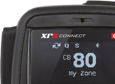
9 Introduction Your GME XRS-370C 80 channel radio is Australian designed and manufactured and is the most advanced UHF Citizen Band radio available. It combines the very latest in electronic hardware with the most up-to-date computer aided design and manufacturing techniques to produce a super compact mobile radio with outstanding specifications, features and performance. The XRS Connect speaker microphone with OLED display and front mounted speaker provides clear sound and total control from the palm of your hand allowing your radio to be mounted almost anywhere in your vehicle. XRS Connect are the first UHF CB radios with an app to configure and control the radio. Visit gme.net.au/getxrs for more information. Features This section lists the various features available on your XRS Connect radio. Transmit (TX) Individually Programmable Duplex Function: User selectable for only those individual channels in your area that have repeaters, leaving the others free for use as extra simplex channels. Receive (RX) Squelch Tail: Can be switched off to eliminate the audible noise burst normally heard when the Squelch closes. User Programmable Receive Channels: 8 zones of 50 channels per zone for a total of 400 additional receive-only channels. Digital Signal-Strength Meter: Provides a numeric signal strength indication in numbers from 0 to 9+. Scanning and memory functions Microprocessor Controlled Frequency Synthesiser: Allows user programmable control of scanning, channel memories and selected feature options. Programmable Scan Function: Scans the selected UHF CB channels with Open, Priority and Network scan functions available. Priority Channel: A user programmable Priority channel for instant recall at the press of a key. 9
10 Signal processing Digital Signal Processing (DSP): Measures, filters and compresses standard analogue audio signals and converts them into digital format. Allows advanced RF and audio processing techniques to be applied to maximise the radio s performance. Advanced Signal Management (ASM): Identifies interference caused by strong local signals on adjacent channels and prevents these from opening your Squelch. ASM also minimises distortion on reception by fine tuning the receiver frequency to match that of the incoming signal. Dynamic Volume Control (DVC): Automatically compensates for variations in received audio level to provide a constant audio output level to the speaker. Privacy functions Voice Inversion Scrambler: When activated, scrambles your voice so that communications are only intelligible to others using the same scrambler technology. In-built CTCSS and DCS: User selectable Continuous Tone Coded Squelch System and Digital Coded Squelch system provides silent operation on individual channels. In-Built SelCall with Quiet Mode: Provides selective calling of individuals or groups with fully user-adjustable 5-tone transmitted SelCall Ident. Also allows alphanumeric naming of up to 20 Idents for easier caller identification. Physical properties Over Voltage Protection: Special over voltage detection circuitry protects the radio and warns of excessive voltage conditions on the display. Rugged Construction: With die-cast chassis. User controls and interface Full Function Controller Microphone: Includes front mounted speaker to channel clear audio towards the user. OLED Display: Bright, high contrast, dot matrix OLED display is readable under all lighting conditions. For a more detailed description of all key functions, refer the General Operation section. 10
11 XRS Connect Apps XRS Connect App The XRS Connect app is the easy way to customize, update and maintain your XRS Connect radio using Bluetooth. To download the free XRS Connect app for ios or Android: 1. Visit App Store or Google Play. 2. Search for XRS Connect. For information on pairing your smart device with your XRS Connect radio, see the Pairing section that follows. When your device is paired to the radio, select the Read from Radio button to read your radio s settings into the app. After you have configured your preferences in the app, select Write to Radio to update your radio with your new settings. XRS Location Services The XRS Location Services app is used with the XRS Connect radio, and is available for ios and Android devices. It connects to the XRS Connect radio using Bluetooth. The app allows users to share their location using the mobile device s GPS location. The location is broadcast by the radio at the end of a normal voice transmission. The location cannot be shared by the app without being connected to an XRS Connect radio. XRS Location Services transmits your geographic location as a supplementary service to voice communication on CB channels. This feature complies with the Radio Communications (Citizen Band Radio Stations) Class Licence GME values your privacy, and does not collect any of your location data. The location data is only stored within the XRS Location Services app and is transmitted from your XRS Connect radio. To use XRS Location Services, download the app to your mobile device and update the radio firmware. Pairing To pair your smart device with your XRS Connect radio: 1. Open the Radios section of the XRS Connect or XRS Location Services app 2. Press the + button to discover new radios. If you don t see your radio, swipe down to refresh the list. 3. Locate your radio in the list and tap the name of the radio to pair. See the Bluetooth section of this manual for information on secure pairing. 4. If secure pairing is turned on; In the radio s Bluetooth menu, navigate to Pair and select it to put the radio into pair mode. You will be asked to confirm a security PIN on both the mobile device and radio. When successfully connected the icon on your radio should change to to show that the Bluetooth pairing is successful. 11
12 The Bluetooth wireless technology enabled connection between your smart device and your XRS Connect radio must be made through the XRS Connect app. You will not be able to pair your smart device to your XRS Connect radio using the normal Bluetooth wireless technology enabled settings option on your smart device. The XRS Connect and XRS Location Services apps are compatible with ios 10.0 and above and Android 5.0 and above. General Operation Front Panel Microphone Socket Rear Panel Extension Speaker Socket 12V DC Socket Antenna Socket 12
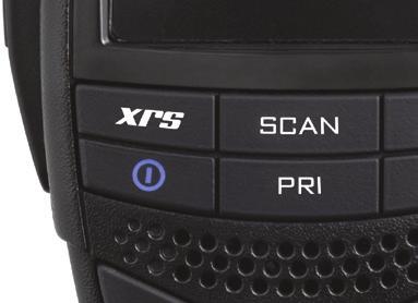
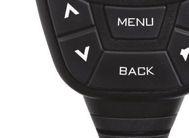
13 Controller Microphone Push to Talk Bu on Programmable (XRS) Func on Key Power Priority Channel Up Microphone Menu/Enter Channel Down Programmable (Top) Func on Key OLED Display Scan Duplex Squelch Speaker Volume + Volume - Back General Power Press and hold the key to turn the radio on. Press and hold the key to turn the radio off. Volume Press the or keys to adjust the volume. Press to increase the volume or to decrease the volume. The volume level is displayed on the OLED Display in values from 01 (min) to 31 (max). If no sound is heard, briefly press the SQL key to temporarily unmute the radio then adjust the volume while listening to the background noise. When finished, briefly press the SQL key again to re-mute the radio. At the minimum volume setting there is still sufficient volume to be heard in a quiet cabin environment. 13
14 Selecting Channels To select a channel, press the or key. Press to select a higher channel or to select a lower channel. The selected channel is displayed on the OLED Display. Press and hold either key to advance quickly through the channels. Squelch The Squelch is used to eliminate any annoying background noise when there are no signals present. The Squelch can be opened or closed using the SQL key. When the Squelch is open the receiver s background noise can be heard and the icon is displayed. When the Squelch is closed the receiver remains quiet while there are no signals present but any incoming signals will override the Squelch and be heard in the speaker. Adjusting the Squelch Level The Squelch sensitivity level has been factory set to provide optimum performance under most operating conditions. If required, the sensitivity level can be adjusted to suit changing conditions. To adjust squelch sensitivity: 1. Press MENU key. 2. Navigate to RADIO SETTINGS > SQUELCH LEVEL. You can use the or key to adjust the squelch level. The default squelch sensitivity level is 3. Signal Meter The signal meter indicates the relative strength of the incoming signal in numerical format. Signal strengths are displayed on the right of the Channel Display in values from 0 to 9. Signals above strength 9 are displayed as 9+. Brightness The OLED display and keys are backlit for easier viewing under a wide range of lighting conditions. The backlight remains on whenever the radio is switched on. The brightness level can be smoothly adjusted in steps from 0 to 10. To adjust brightness level: 1. Press the MENU key. 2. Navigate to RADIO SETTINGS > BRIGHTNESS. You can use the or key to adjust the brightness. 14
15 A Dim function can also be assigned to the programmable XRS key to quickly switch the brightness level to minimum for low light viewing. This saves having to manually readjust the brightness level when moving into low light environments. To assign the Dim function to a key, press the MENU key and navigate to Prog Buttons and its options to configure this feature. Transmitting Prior to transmitting, always check the channel is clear. This can be done by listening to the channel or by visually checking that the icon is not visible or the signal meter is not indicating a signal. To transmit: 1. Press the PTT on the microphone. The icon will appear. 2. Hold the microphone about 3-5 cm from your face and speak at a normal voice level. Since the microphone is quite sensitive, it is not necessary to raise your voice or shout. 3. Release the PTT when you have finished talking, the icon will disappear. Always listen to ensure the channel is free before transmitting. Time-out Timer The radio has a built-in time-out timer that automatically limits transmissions to a maximum of 3 minutes of continuous operation. This feature is required by the ACMA to prevent accidental blocking of the frequency should your PTT become jammed or be otherwise pressed accidentally. When the time-out timer activates, the radio will give a low tone for a few seconds and the transmitter will be temporarily disabled. Release the PTT to restore normal operation. Busy Lockout When enabled, the Busy Lockout function detects when someone is transmitting on the channel and prevents your radio from transmitting over them. If you press the PTT when the channel is busy the radio will emit a warning beep and the icon won t be displayed. If this happens, look for the icon on the display as an indicator that the channel is already in use. If the channel is busy, simply wait until the channel is clear and press the PTT again. When Busy Lockout is disabled, you should check that the channel is clear before pressing the PTT to avoid transmitting over others who may be already transmitting on the channel. To enable/disable busy lockout: 1. Press the MENU key. 2. Navigate to select RADIO SETTINGS > BUSY LOCK. You can use the or key to turn this function on or off. 15
16 Voice Scrambler Your radio incorporates a simple voice scrambler using band inversion. The scrambler is compatible with the majority of scramblers used by other manufacturers, allowing you to enjoy scrambled communications with owners of non-gme radios. Once the scrambler has been activated your transmission and reception will only be intelligible to others using the same scrambler technology. To enable/disable voice scrambler: 1. Press the MENU key. 2. Navigate to select RADIO SETTINGS > SCRAMBLER. You can use the MENU key to turn this function on or off. To avoid interference with other services or users, the scrambler cannot be enabled on channels 5, 11, 22, 23, 31-38, 61, 62, 63, or on any channel that has been set to Duplex mode (1-8). Beep Tone Volume The Beep tone provides audible feedback whenever the keys are pressed. The Beep tone volume can be adjusted in values from To switch the beep off, select 0. To adjust volume of beep tone: 1. Press the MENU key. 2. Navigate to select RADIO SETTINGS > BEEP VOLUME. You can use the or key to increase or decrease the beep tone. Dynamic Volume Control (DVC) The modulation level of signals heard on the UHF CB band has always varied considerably resulting in noticeable differences in received audio volume between stations. Generally, users have compensated for this by adjusting the Volume control for each incoming signal. With the introduction of 80 channel narrow band transmissions that use lower levels of modulation, the differences in received audio volume is likely to increase further. Your XRS Connect radio is able to automatically compensate for these variations by utilising a Dynamic Volume Control. When activated through the menu, this feature automatically compensates for variations in received audio level resulting in a constant audio output level to the speaker. To activate/deactivate Dynamic Volume Control: 1. Press the MENU key. 2. Navigate to select RADIO SETTINGS > DYNAMIC VOL. You can use the MENU key to turn this function on or off. 16
17 Selecting the Active Speaker The XRS-370C radio has two speakers - one mounted inside the radio and the other mounted inside the microphone. By default, sound is reproduced by both speakers; however if you prefer, one of these speakers can be switched off, leaving either the radio s internal speaker or the microphone s speaker to reproduce sound. To select speakers: 1. Press the MENU key. 2. Navigate to select RADIO SETTINGS > SPEAKER. You can use the or key to select an option. Microphone Gain The microphone gain controls the sensitivity of the microphone to your voice input level. If you are quietly spoken or are operating in a quiet environment you can increase the microphone gain to make your voice sound clearer. If your voice is quite loud or you are working in a noisy environment and wish to minimise the amount of background noise that is picked up, you should reduce the microphone gain. To adjust microphone gain: 1. Press the MENU key. 2. Navigate to select RADIO SETTINGS > MIC GAIN. You can use the or key to increase or decrease the microphone gain. The Microphone Gain provides a fine adjustment to the microphone sensitivity. A wider adjustment range is available through the XRS Connect App. Squelch Tail The Squelch Tail is the short burst of noise that is heard in the speaker at the end of a transmission just before the Squelch closes. To some it is a reassuring confirmation that it is their turn to transmit but in some applications it may be an annoyance especially when listening through an ear piece or headphones. The Squelch Tail can be turned off, reducing it to a faint click as the Squelch closes. To enable/disable squelch tail: 1. Press the MENU key. 2. Navigate to select RADIO SETTINGS > SQUELCH TAIL. You can use the MENU key to turn this function on or off. 17
18 Repeater and Duplex Mode Duplex operation allows the radio to transmit on a different frequency to that which it receives. This allows operation through repeater stations. A repeater station consists of a linked transmitter/receiver combination installed in a prominent location. The repeater is designed to receive signals on a designated channel and retransmit them on another channel. Repeaters are usually mounted on hills or tall buildings. The increase elevation greatly improves both the receiving and transmitting range of the repeater allowing it to receive and retransmit signals to radios that would otherwise be out of range of each other. Normally, UHF CB radios transmit and receive on the same frequency - known as Simplex operation. However, to communicate through repeaters, your radio must be able to transmit and receive on different channels - otherwise known as Duplex operation. Your radio is fitted with a Duplex key to allow you to operate through repeaters. The Duplex function can only be selected on channels 1-8 and as these are the channels that have been allocated for repeater use. When Duplex is selected, your radio receives on the selected channel (e.g. CH 1) but transmits 30 channels higher (CH 31). The repeater hears your signal on CH 31 and retransmits it on CH 1 for others to hear. Your XRS Connect radio allows you to enable or disable Duplex mode on individual repeater channels. In this way any repeater channels that are not being used with repeaters in your area can be used in Simplex mode for normal direct radio-to-radio communications. To enable duplex on a repeater channel: 1. Select the required repeater channel (1-8, 41-48). 2. Briefly press the DUP key. The icon will appear on the display accompanied by a high beep. To remove duplex from a repeater channel: 1. Select the required repeater channel (1-8, 41-48). If duplex is currently selected, the icon will be displayed. 2. Briefly press the DUP key. The icon will disappear from the display accompanied by a low beep. Channels 1-8, 31-38, and should only be used in Simplex mode if there are no repeaters in or near your location that operate on the selected channel. In particular, avoid operating in Simplex mode on any of the repeater input channels and unless you are absolutely sure that there are no repeaters in range using that channel. Inadvertently transmitting on an active repeater input frequency in simplex mode could cause interference to other users on that repeater who might not be audible to your radio. 18
19 Priority Channel The Priority channel feature allows you to instantly recall any one of the 80 CB channels in your radio. This feature can be used to provide instant access to your working channel or your local repeater channel at the press of key. It is also used in conjunction with the Priority Scan mode. To store a priority channel: 1. Select the required channel. 2. Press and hold the PRI key. The channel number will flash for a few seconds then a high beep will be heard as the channel is stored. The PRI icon will now be visible whenever that channel is selected. The Priority channel can also be set through the Menu. To recall a priority channel: Briefly press the PRI key. The radio will immediately switch to the Priority channel and the PRI icon will be displayed. If the radio was scanning when the Priority channel was recalled, the scan will be cancelled. Voice Playback You can enable this feature to allow the radio to record voice transmissions that it receives from other radios, and then playback recorded transmissions. The following are the basic functionalities of the Voice Playback feature: Records the first 30 seconds of every transmission received by your radio. Stores a total of 12 minutes of recordings (combined time of all recordings). When playback begins, the radio begins with the most recent recording. If you scroll back through the list to an older recording, it will play that recording and then work its way through the list to the most recent recording. You can use the or key to scroll through the list of recordings. On selecting each recording, the radio s screen displays the following: Name of the recording. Elapsed time since the recording was made (If the radio is switched off, this information will be no longer be available when the radio is switched on). To enable the voice playback feature: 1. Press the MENU key. 2. Navigate to the VOICE PLAYBACK menu option, and press the MENU key to select. 3. Select ENABLE. 19
20 To playback voice recordings: When navigating from the main menu: 1. Press the MENU key. 2. Navigate to the VOICE PLAYBACK menu option, and press the MENU key to select. 3. Select PLAYBACK. Alternatively, you can assign the Voice Playback feature to one of the programmable keys (XRS key, or the top programmable key). When the key is pressed, it will begin playback. To exit the voice playback feature, press the BACK key. Pressing the PRI key or PTT key will also immediately exit the voice playback feature. To clear all recordings: 1. Press the MENU key. 2. Navigate to the VOICE PLAYBACK menu option, and press the MENU key to select. 3. Select CLEAR ALL. This selection erases all recordings from the radio. Scanning Your radio incorporates a scan function allowing selected groups of channels to be scanned for signals. Channels can be scanned at a rate of 50 channels per second. When a signal is found, scanning will pause to allow the signal to be heard then resume scanning when the channel is clear again. Scan groups Your radio supports three scan groups: Open Scan: Allows you sequentially scan from 2 to 80 user-selectable CB channels. Priority Scan: Allows you constantly monitor your priority channel while scanning a group of user-selectable CB channels. Network Scan: Allows a group of radio users to maintain communications even when the band is congested by monitoring a small group of user selectable channels. If the operating channel becomes busy with users from outside your group, Net-Scan will automatically select a new free channel from the scan group and transparently switch all users in your group to the new channel. To select open scan/priority scan/network scan: 1. Press the MENU key. 2. Navigate to select SCAN SETTINGS, and the required scan option. 20
21 Programming the scan memories Each Scan Group has its own separate channel memory allowing you complete freedom to program your choice of channels into each group. To add/remove channels from the selected scan memory: 1. Select the required channel using the or key. 2. Check to see if the icon is displayed on that channel. If is displayed, the selected channel is already in the scan memory. To remove it, press and hold SCAN. A low beep will be heard and will disappear. If is not displayed, the selected channel is not in the scan memory. To add it, press and hold SCAN. A high beep will be heard and will appear on that channel. Repeat to add or remove other channels in the scan memory. When adding channels to Net-Scan, please consider the following: The transmitter on your radio is inhibited on channels 22, 23 and channels 61, 62, 63 as required by the ACMA. This makes these channels unsuitable for use as Net-Scan channels. You should not include any repeater channel unless you have confirmed that the channel is not allocated to repeaters in your area. Using an active repeater channel in Net-Scan may result in interference to repeater users on that channel. Auto skip While scanning, if an active channel in your Scan Group becomes a nuisance by constantly interrupting the scan, briefly press or while the radio is paused on that channel. The busy channel will be temporarily removed from the Scan Group to allow time for the channel to become clear again and scanning will continue from the next channel in the sequence. After 30 seconds the skipped channel will be reinstated in the scan sequence. If the unwanted active channel continues to interrupt the scan even after the 30 second skip period has elapsed, hold SCAN while the radio is paused on that channel. The nuisance channel will be completely removed from the Scan Group for the duration of that scan session. To restore the channel, simply stop and restart the scan session using the SCAN key (or switch the radio Off then On again). You can skip as many busy channels from the Scan Group as you wish, however if you attempt to skip the last remaining channel, all the previously skipped channels will be restored to the Scan Group. The length of the skip period can be adjusted through the XRS Connect App. 21
22 Open Scan Open Scan allows a group of channels to be scanned in an ascending sequence. If a signal is found, the scan will pause on that channel. During this time you can press the PTT on the microphone and talk on the channel. Once the channel has been clear for 5 seconds the scan will resume. Selecting Open Scan To select open scan: 1. Press the MENU key. 2. Navigate to select SCAN SETTINGS. The default working channel is in the Open Scan mode. In the Open Scan mode, your default working channel is the channel your radio switches to when you press the PTT while scanning. To set your working channel simply select the required channel before you press SCAN. e.g. to make channel 24 your working channel, simply select channel 24 before pressing SCAN. To begin scanning: Briefly press SCAN. A high beep will be heard, SCANNING will be displayed and the icon will animate. During this time the scan mode and the number of channels being scanned will be displayed along with the selected Zone. If there are less than 2 channels programmed into the scan memory when you press SCAN, a low beep will be heard and the command will be ignored. Operating in the Open Scan Mode If a busy channel is found, scanning will pause to allow the signal to be heard and will remain there for as long as the channel remains busy. Once the channel has been clear for 5 seconds, scanning will resume automatically. If you don t wish to listen to a busy channel, briefly press or while the radio is paused on that channel. The busy channel will be temporarily removed from the Scan Group to allow time for the channel to become clear again and scanning will continue. The skipped channel will be reinstated in the scan sequence after 30 seconds (see Auto Skip). 22
23 If you press the PTT while the radio is scanning, the scan will pause and the radio will transmit on the working channel. After the channel has remained clear for 5 seconds scanning will resume. If your radio pauses on a busy channel and you wish to talk on that channel, wait for a break in the conversation then press the PTT. If the busy channel was not your working channel, it now becomes your working channel, replacing your previous working channel. Once your communication has finished and the channel has been clear for 5 seconds, scanning will resume. If you need to use your Priority channel at any time, briefly press PRI. The scan will be cancelled and the radio will jump straight to the Priority channel. Priority Scan Priority Scan allows you to scan a number of channels for activity while also monitoring your Priority channel. The receiver will scan the other channels only while there are no signals on the priority channel. If a signal appears on the Priority channel it will override any signals being received on any of the other channels. In addition, if you press the PTT at any time, the radio will transmit on the Priority channel. Example: Scanning channels 1-8 with priority channel 20 in Priority Scan By default the priority channel will be scanned after every 5th scan channel. This timing can be adjusted using the XRS Connect App. Selecting Priority Scan To select Priority Scan, refer to the Menu/Scan Settings options. To begin scanning Briefly press SCAN. A high beep will be heard, SCANNING will be displayed and the icon will animate. During this time the scan mode and the number of channels being scanned will be displayed along with the selected Zone. If a signal appears on the Priority channel - at any time - the radio will switch directly to the Priority channel and will stay there for as long as the channel remains busy. During this time you can transmit and receive on the Priority channel. Once the Priority channel has been clear for 5 seconds the radio will resume scanning the other channels. 23
24 If a signal appears on any other channel, scanning will pause on that channel and will remain there while the channel is busy - as long as there are no signals on the Priority channel. During this time, the receiver will continue to check the Priority channel every 2 seconds resulting in a series of small breaks in the reception. Once the signal has gone and there has been no activity for 5 seconds, the radio will resume scanning. If the radio is paused on a busy channel and you want to remain there, briefly press SCAN. The radio will exit scan and remain on the busy channel. At this point you will no longer be monitoring the Priority channel. To resume the Priority Scan, press SCAN again. If you don t wish to listen to a busy channel, briefly press the or key while the radio is paused on that channel. The busy channel will be temporarily removed from the Scan Group to allow time for the channel to become clear again and scanning will continue. The skipped channel will be automatically reinstated in the scan sequence after 30 seconds (see Auto skip ). To transmit on the Priority channel at any time, simply press the PTT. The radio will switch straight to the Priority channel. When you have finished your conversation and there has been no further activity for 5 seconds, the radio will resume scanning the other channels. To jump straight to the Priority channel at any time, briefly press the PRI key. The scan will be cancelled. Network Scan (Net-Scan) Net-Scan allows a group of radio users to maintain communications even when the band is congested. To achieve this, all members of the Net-Scan group must share a common CTCSS/DCS code and a common set of scan channels. Once activated, Net-Scan s intelligent scanning software keeps track of clear channels within your Scan Group. When any member of the group first transmits, their radio automatically selects a clear channel to transmit on. Other radios scanning in the same Net-Scan group will detect the common CTCSS/DCS code and lock onto that channel allowing all members of the group to join the conversation. If a signal from outside your Net-Scan group transmits on the selected channel without using your chosen CTCSS/DCS code, the group will automatically switch to a new clear channel at the next transmission. In this way the group can continue to communicate with minimal interference to or from other users. Enabling Net-Scan To select network scan and a suitable CTCSS/DCS code: 1. Press the MENU key. 2. Navigate to select SCAN SETTINGS and choose from the options available. 24
25 Using Net-Scan With Net-Scan mode enabled, briefly press SCAN. A high beep will be heard, SCANNING will be displayed and the icon will animate. During this time the scan mode and the number of channels being scanned will be displayed along with the selected Zone. When a member of the group initiates a transmission their radio will automatically select a clear Net-Scan channel to transmit on. Other radios scanning in the same Net-Scan group will locate the transmission by identifying the groups CTCSS/DCS code, pause on that channel and open their Squelch, allowing the transmission to be heard across the entire group. When the transmission ends, all radios in the group will immediately resume scanning. If a member of the group responds to the initial transmission, they will automatically re-use the same channel as long as the channel remains free of other signals. This allows the radios in the group to respond more quickly to further transmissions from others in the group. If at any time a signal from outside your Net-Scan group transmits on the selected channel without using your chosen CTCSS/DCS code, the channel will be discarded and a new clear channel will be selected at the next transmission. The other radios in the group will then relocate to the new channel allowing the conversation to continue seamlessly without any input from the user. Ending the Scan To stop scanning, briefly press SCAN. A low beep will be heard and the icon will stop animating. As long as the radio was not on a busy channel, it will return to the last channel you selected, otherwise it will stay on the busy channel. CTCSS and DCS The standard Squelch system operates solely on signal strength which means that it will open to any signal that is strong enough. If the selected channel is busy with other stations the Squelch will be opening constantly making it difficult to determine which calls are meant for you. CTCSS (Continuous Tone Coded Squelch System) and DCS (Digital Coded Squelch) are similar Squelch quieting systems that provide selective audio muting using sub-audible signalling. When CTCSS or DCS is enabled, only signals with a matching sub-tone will be heard in the speaker. This effectively creates a channel that is silent to all traffic except those you wish to hear. 25
26 Choosing CTCSS or DCS The CTCSS system uses 1 of 50 low frequency tones to open and close the Squelch on the radio. The DCS system is similar to CTCSS but uses 1 of 104 digital codes to control the Squelch. There is no difference in performance or function between CTCSS or DCS so choosing which system to use will largely depend on the other radios you talk with. If others already use CTCSS or DCS, you should select the system that matches theirs. If the users you talk to don t currently use CTCSS or DCS then you can make your own choice. Both types are included in the radio to maintain compatibility with other radio systems. CTCSS tone set compatibility The GME CTCSS tone set comprises 50 tones made up of the standard CCIR-38 Tone Set plus an additional 12 tones added to the end. If communicating with other brands of radios that only use the CCIR-38 tone set, please select from one of the first 38 tones to ensure compatibility with these radios. If communicating with other GME radios, you may choose from any of the 50 tones. However, to ensure compatibility, please refer to the tone set table listed in each radio s Instruction manual because the tones used in older GME models may be listed in a different order to those in your radio. To select a CTCSS or DCS code, refer the Menu/Radio Settings options. Enabling CTCSS/DCS on a channel (Silent mode) Enabling CTCSS/DCS on a channel will prevent the Squelch from opening on that channel unless the incoming signal matches your selected CTCSS/DCS tone. Other users on the same channel who are not using your CTCSS/DCS tone will still be received by your radio (the con will still appear on the display) but they will not be heard in the speaker. Only when someone transmits on the channel using your CTCSS/DCS tone will the Squelch open to allow the signal to be heard. Channels where CTCSS/DCS have been enabled are said to be in Silent mode. Silent mode can be enabled on any channel except emergency channels 5 and 35. To enable silent mode on a channel 1. Press the MENU key. 2. Navigate and select FUNCTIONS > TOGGLE SILENT. 3. Press the MENU key to select ON An icon (CTCSS) or icon (DCS) will be displayed at the top of the display to indicate Silent mode is now enabled on that channel. You cannot enable Silent mode unless a CTCSS or DCS tone has been selected in the RADIO SETTINGS menu. If CTCSS/DCS has been set to OFF, Silent mode is inhibited. 26
27 To disable silent mode on a channel 1. Press the MENU key. 2. Navigate and select FUNCTIONS > TOGGLE SILENT. 3. Press the MENU key to select OFF 4. The icon (CTCSS) or icon (DCS) will be disappear from the display to confirm Silent mode is now disabled on that channel. When Silent mode is enabled on a channel you should always check the icon for signs of traffic on the channel before transmitting to ensure you do not accidentally transmit over the top of another user. Alternatively, you can enable Busy Lockout in the menu which will automatically prevent your radio from transmitting if the channel is already in use. Busy Lockout When using Silent mode with CTCSS/DCS, your radio s receiver remains quiet to all signals outside your CTCSS/ DCS group. As a result, if you do not notice when others are transmitting on your channel you could accidentally transmit over the top of them. The Busy Lockout function detects when others outside your CTCSS/DCS group are transmitting on the channel and prevents your radio from transmitting over them. If you press the PTT when the channel is busy the radio will emit a warning beep and the icon won t be displayed. If this happens, look for the icon on the display as an indicator that the channel is in use. If the channel is busy, simply wait until the channel is clear and press the PTT again. To enable or disable busy lockout, 1. Press the MENU key. 2. Navigate to RADIO SETTINGS > BUSY LOCK. Use the MENU key to enable or disable this feature. A Busy Lockout Override with CTCSS Match option is available through the XRS Connect App. When this option is enabled, Busy Lockout will not prevent you from transmitting over the top of another signal where their CTCSS/DCS code matches yours (i.e. The signal is from a member of your group). Monitor function When the current channel is in Silent mode, you may see the icon appear but hear no sound in the speaker. This indicates that your radio is receiving a signal that does not match your CTCSS/DCS tone. Press the key to briefly monitor signals on the channel. The Silent mode will be temporarily disabled while the key is pressed allowing you to hear signals on the channel. When you release the key, Silent mode is restored and the radio becomes quiet again. You will only have a brief moment to monitor the channel for signals because holding the key for more than a few seconds will switch the radio off. 27
28 Selective Calling Your radio has a Selective Calling system known as SelCall that operates like a telephone. Your radio is pre-programmed with its own unique SelCall Identification number. If this number is called by another radio, your radio will beep to alert you. If you do not want to hear any other activity while waiting on a channel, you can select the QUIET mode. Your radio will then remain quiet to all incoming signals until your SelCall number is called. You can store up to 20 of your most frequently called SelCall numbers in memory and each number can be labelled for easy identification. SelCall Identification Number Your radio is factory programmed with its own unique SelCall Identification Number. This number identifies your radio from others in your area. Your radio s own SelCall Ident will be displayed for a few seconds to the lower-left of the display when you first turn the radio on. You will need to make your Ident known to anyone who may need to call you using SelCall. Although your radio is factory-programmed with a unique SelCall Ident, you can change your Ident to another number if required, using the Menu/Selcall option. SelCall naming When storing SelCall numbers, you can add names to each one to make it easier to identify whose number you are recalling. In addition, if an incoming SelCall matches one of your stored numbers, the name will be displayed to identify the caller. The Quiet mode Your radio can be set to monitor signals on a busy channel but remain Quiet unless it receives its own SelCall Ident. In this way, you won t be disturbed unless someone calls you. When your SelCall Ident is received, the Quiet mode is deactivated and an alarm sounds to alert you to the call. You can then converse normally on the channel. The QUIET mode overrides the normal Squelch system to ensure that the radio remains quiet even when the channel is busy. When QUIET is set, you may see the icon appear on the display indicating the channel is being used. However, unless someone transmits your SelCall Ident, nothing will be heard in the speaker. You can activate the QUIET mode on individual channels (i.e. Some channels can be set to remain Quiet while others can remain open to all incoming signals) by storing those channels into a Quiet Memory. 28
29 Sending a SelCall To send, program or change a SelCall number: 1. Press the MENU key. 2. Select SELCALL and its options. Receiving a SelCall When your radio receives its own SelCall number, the icon will appear along with the callers SelCall number and name and the radio will sound an alarm to alert you to the call. During this time the alarm will beep urgently and the Quiet mode (if enabled) will open to allow incoming calls to be heard. After 30 seconds, if the call is not answered, the alarm will slow and the Quiet mode will be reactivated. The alarm will then continue to beep slowly until you cancel it. To cancel the alarm, but leave the incoming SelCall Ident on the display: Briefly press the TOP key on the top of the microphone. The alarm will stop but the caller s name and SelCall number will remain on the display and the channel will remain open to any incoming signals. This feature is useful if you are currently busy but intend to call the person back later. To cancel the alarm and talk on the channel: Press the PTT and talk in the usual way. The alarm will be canceled, the display will return to normal and the channel will be open for normal communication. To clear the alarm completely: Briefly press BACK. The alarm will be canceled and the display will return to the normal screen. Quiet mode The Quiet mode mutes the receiver to prevent incoming signals from being heard in the speaker until your SelCall Ident is received. In this way you can monitor a busy channel for personal calls without being disturbed by unwanted signals. If your SelCall number is received, the Quiet mode is cancelled and all incoming signals are heard in the speaker. Setting up the Quiet mode To setup the Quiet mode you must first store the individual channels that you want to stay quiet into the Quiet memory. When the required channels are stored, simply activate the Quiet mode and all stored channels will remain quiet to all incoming signals unless your SelCall Ident is received. Channels not stored in the Quiet memory will remain open to all signals and will operate normally. 29
30 To store individual channels into quiet memory: 1. Select the required channel. 2. Press the MENU key, and select FUNCTIONS. 3. Select TOGGLE Q MEM and press MENU to select ON or OFF. When Quiet memory is switched ON on the selected channel, Q will appear at the top of the display indicating the selected channel is now stored in the Quiet memory. When Quiet memory is switched OFF on the selected channel, Q will disappear from the display indicating the channel is no longer stored in the Quiet memory. Activating the Quiet mode 1. Select a channel that has been stored in the Quiet memory. Q will be displayed. NOTE: You cannot activate the Quiet mode unless you have selected a stored channel. 2. Press the MENU key, and navigate to select FUNCTIONS > TOGGLE QMode. 3. Press the MENU key to select from the ON or OFF options. When Quiet mode is switched ON, will appear at the top of the display indicating that Quiet operation is enabled. Now, all channels stored in the Quiet memory will operating in the Quiet mode. When Quiet mode is switched OFF, will disappear from the display indicating that Quiet operation is disabled. Now, all channels stored in the Quiet memory will be open for signals. Receiving signals in the Quiet mode If a normal signal is received on a Quiet channel, the channel will appear busy (the icon will be visible) but no sound will be heard from the speaker. If a normal signal is received on an Open channel (one that is not in the Quiet memory) the signal will be heard in the usual way. If your SelCall Ident is received on any channel - Open or QUIET - the Quiet mode will be cancelled and the alarm will beep to alert you to the call. In addition, the caller s name and number will be displayed. All channels will now be open for normal transmission and reception. Scanning in the Quiet mode The radio will allow you to scan while the QUIET mode is active. Using this feature you can monitor a group of Quiet channels or a combination of Quiet and Open channels. To ensure reliable SelCall detection when scanning in the Quiet mode, it is recommended that you restrict the number of channels in the Scan Group. 30
31 Group Calling The SelCall system includes a Group Call function that allows you to call up to 1000 radios simultaneously. This can be useful in an emergency situation where you may need to transmit a message to a large number of radios in your group. By default, your radio is factory-set to allow up to 10 radios to be called at once. If your application requires more, your dealer can re-program this option to allow 100 or even 1000 radios to be called. The following description assumes the default Group Call setting of 10 radios. The Group Call function works by allowing you to enter a special group code into the last digit of the SelCall number you are sending. The group code appears as an A (All) when displayed in the radio. When this group code is received, it substitutes for all other numbers in that position. As long as the first 4 digits of the SelCall you are sending match those of the radios you are calling, their SelCall alarm will be activated as if their full 5 digit SelCall Idents had been received. To achieve this, the 10 radios you are calling have sequentially numbered SelCall Idents. e.g , 14531, 14532, 14533, 14534, 14535, 14536, 14537, 14538, Transmitting the SelCall Ident will only activate the alarm in the radio with the SelCall Ident of However, transmitting 1453A will activate the alarms in all radios with Idents through (a total of 10 radios). If the radios in your fleet do not have sequential SelCall number and you want to make use of this function, you will need to re-program the SelCall Idents in your radios by changing the numbers in your radio s OWN SelCall memory. Programming and sending group calls The process for entering a Group Call Ident is the same as entering a normal SelCall Ident. The 1. Press the MENU key. 2. Use the or keys to select SelCall and press MENU to select. 3. Select MAKE SELCALL and press MENU. 4. Use the or keys to change the digit at the cursor position. Press MENU [SEL:NEXT] to step forward to the NEXT digit position or BACK to step back to the previous digit position. 5. Repeat until the first 4 digits have been entered. At the last digit use the or keys to select A. 6. Hold MENU [HLD:CALL] to send. icon will be display as the SelCall is transmitted. Where your radio allows it, programming Group Calls for 100 radios is identical except that you will need to select A for the last two digits (e.g. 123AA). For 1000 radios you will need to select A for last three digits (e.g. 12AAA). 31
32 Call acknowledge in group mode There is no Call Acknowledge when sending Group Calls. This is to prevent all the radios in your group from trying to respond to your SelCall transmission at the same time. Storing group call idents Group Call Idents can be stored in memory in the same way as a standard SelCall Ident. Receiving group calls Receiving a Group Call is identical to receiving a normal SelCall except that the alarm sound is a LOW tone beep instead of the normal High tone beep. The caller s name and number is displayed in the usual way. Menu Options The Menu provides access to all the settings, adjustments and functions listed in the table below. All menu items are controlled using the MENU,, and BACK keys. 1. To access the menu, press the MENU key. 2. To scroll through the list of menu items press the or keys. 3. To select an item, press the MENU key. 4. To step back through the menu, or to exit the current screen, HOLD the BACK key. A context menu is included at the bottom of each screen. The options offered will change depending on the selected topic. SEL:OPTION = briefly press the MENU key to select the option. HLD: OPTION = press and hold the MENU key to select the option. 32

33 Context menu examples SEL:NEXT = Press MENU for NEXT HLD:CALL = Hold MENU for NEXT SEL:EDIT = Press MENU for EDIT HLD:OPTIONS = Hold MENU for OPTIONS When entering text (e.g. zone names or SelCall numbers), the following characters are available; Text Uppercase Letters Lowercase Letters Numbers Punctuation Available Characters A B C D E F G H I J K L M N O P Q R S T U V W X Y Z a b c d e f g h i j k l m n o p q r s t u v w x y z. * + <space> 33
34 Menu Table Menu Option Options Option Settings ZONES Zone 01 Zone 02 Zone 03 Zone 04 Zone 05 Zone 06 Zone 07 Zone 08 BLUETOOTH PROG BUTTONS FUNCTIONS RADIO SETTINGS Secure pair Pair XRS BUTTON PRESS XRS BUTTON HOLD TOP BUTTON PRESS TOGGLE Q MEMORY TOGGLE Qmode TOGGLE SCAN TOGGLE SILENT BEEP VOLUME BRIGHTNESS BUSY LOCKOUT CB SUBTONE DYNAMIC VOLUME CONTROL MIC GAIN PRIORITY CHANNEL SCRAMBLER SPEAKER SQUELCH LEVEL SQUELCH TAIL SELCALL ACK VERSIONS RESET SETTINGS GO/EDIT ON/OFF DISPLAY DIM CB SCAN MEMORY QUITE MEMORY QUIET MODE SCRAMBLER SQUELCH LEVEL ZONES VOICE PLAYBACK CYCLE SCAN MEMORY SELCALL VOICE PLAYBACK ON/OFF ON/OFF ON/OFF ON/OFF SCAN SETTINGS CB SCAN MEMORY A Open Scan B Priority Scan C Network Scan SELCALL NETSCAN SUBTONE MAKE SELCALL Last Own Memory to 10 0 to 10 ON/OFF CTCSS/DCS Tones ON/OFF +0dB to +9dB CB01 to CB80 ON/OFF Radio, Mic, Both 1 to 9 ON/OFF ON/OFF Model, Serial #, Firmware, Bluetooth H/W, Bluetooth F/W Cancel, Reset radio, Factory Reset CTCSS/DCS 34
35 Menu Option Options Option Settings LOCATION SERVICES VOICE PLAYBACK LOCATION TX LOCATION TIMEOUT MIC DISPLAY SELCALL UID ENABLE CLEAR ALL PLAYBACK ON/OFF minutes Loc/OFF/Txt ON/OFF ON/OFF Receive-only channels (zones) Your XRS Connect radio can store up to 400 user-programmable receiveonly channels within the frequency range of 403 MHz to 520 MHz. Channels are stored in one of 8 zones with each zone containing up to 50 channels. Zones and channels can each be individually named for easy identification. Programming is done either through the radio menu or through the GME XRS Connect App. The XRS Connect App also offers a range of pre-programmed frequencies in various categories sorted by locations making the selection of suitable channels and frequencies much easier. When a Zone is selected, its frequencies will be added to the standard 80 CB channels. Zone channels appear immediately above CH80. After the last zone channel is selected channels will wrap around to CH01 again. Select a Zone 1. Press the MENU button. 2. Select ZONES and press MENU. 3. Select the desired Zone from the Zone list. 4. Press MENU [SEL:GO]. 35
36 The radio returns to the main screen with the selected zone displayed below the channel number. All channels in the selected zone will now be available along with the usual 80 CB channels. Zone channels can be found immediately above CB Channel 80. Edit a Zone Name 1. Press the MENU key. 2. Select ZONES and press MENU. 3. Select the desired Zone from the Zone list and HOLD MENU [HLD:EDIT] to edit the zone. The zone edit screen appears. 4. Press MENU [SEL:EDIT] to edit the zone name. 5. Use the or keys to change the character at the cursor position. 6. Press the MENU key to step forward to the NEXT character position or the BACK key to step back to the previous character position. 36
37 7. Continue until the desired name has been entered. Zone names can be up to 16 characters long. 8. To save the name HOLD the MENU key [HLD:SAVE]. The radio will return to the Zone list with the new zone name displayed. Add Channels to a New Zone 1. Press the MENU key. 2. Select ZONES and press MENU. 3. Select the desired Zone from the Zone list and HOLD MENU [HLD:EDIT] to edit the zone. 4. Hold MENU [HLD:OPTIONS] to select Options. 5. Use the or keys to select ADD CHANNEL from the menu list. 6. Press MENU [SEL:EDIT] to edit the new channel. 37
38 7. Use the or keys to change the character at the cursor position. 8. Press MENU to step forward to the NEXT character position or the BACK key to step back to the previous character position. 9. When the desired name has been entered, press the MENU key repeatedly to step to the RX frequency. Channel names may contain up to 16 characters. 10. Press the MENU key repeatedly to step to the RX frequency. 11. Use the or keys to change the frequency digit. 12. Press MENU to step to the NEXT digit position or BACK to return to the previous digit position. When editing the khz digits the entire block of KHz digits will change in 12.5 khz steps. 13. To save the new channel, hold MENU [HLD:SAVE]. The display returns to the Zone screen. 38
![Edit Existing Channels in a Zone 1. Press the MENU key. 2. Select ZONES and press MENU. 3. Select the desired Zone from the Zone list and hold MENU [HLD:EDIT] to edit the zone. 4.](/docs-images/89/100777480/images/39-3.jpg "Use the or keys to select a channel 5. Hold MENU [HLD:OPTIONS] for the Options menu. 6. Use the or keys to select from the options list them press MENU.")
39 Edit Existing Channels in a Zone 1. Press the MENU key. 2. Select ZONES and press MENU. 3. Select the desired Zone from the Zone list and hold MENU [HLD:EDIT] to edit the zone. 4. Use the or keys to select a channel 5. Hold MENU [HLD:OPTIONS] for the Options menu. 6. Use the or keys to select from the options list them press MENU. Select Go Channel to jump to the select channel Select Del Channel to delete the selected channel Select Add Channel to add a new channel Select Edit to edit the selected channel 7. Next select MENU [SEL:EDIT]. 8. To add a new channel or EDIT an existing channel; 9. Use the or keys to change the character or digit at the cursor position. 10. Press MENU to step forward to the NEXT character or digit position or the BACK key to step back to the previous character or digit position. 39
40 11. Continue until the name or frequency has been edited. 12. Hold MENU [HLD:SAVE] to save. Bluetooth Secure Pairing Use this to turn secure PIN pairing on or off for your Bluetooth connection. If Secure Pairing is turned on when pairing your mobile device with the XRS Connect radio for the first time, you will be asked to confirm a security PIN on both the mobile device with the XRS Location Services app and your radio. With Secure Pair turned on you must put the radio into Pair mode using the PAIR menu option, before connecting your XRS Location Services app. Pair When Secure Pairing is turned on you must select PAIR in the Bluetooth menu to put the radio into pair mode before you can connect for the first time. Pair mode will timeout after 90 seconds. 40
41 Programmable Buttons Programmable (Top) Func on Key Programmable (XRS) Func on Key Button Option Description XRS button press XRS button hold Display Dim CB Scan Memory Quiet Memory Quiet Mode Scrambler Dims the display and keypad backlight. Cycles through the three scan memories. Stores channels in the SelCall Quiet memory. Toggles SelCall Quiet mode between on or off. Enables or disables the scrambler option. Squelch Level Adjusts the preset squelch level in steps from 1 to 9. Zones Voice Playback Displays the Zone list menu for quick zone selection. Plays back recorded transmissions. Top button press Cycle Scan Memory Cycles through the channels stored in the current scan memory. SelCall Call function Voice Playback Programming the XRS Button: 1. Press the MENU key. Provides the standard Call button functions i.e. Press to enter SelCall entry menu Hold to send last SelCall. Plays back recorded transmissions. 2. Use the or keys to select PROG BUTTONS then press MENU to select. 3. Use the or keys to select XRS BUTTON PRESS or XRS BUTTON HOLD then press MENU. 41

42 4. The XRS Button option list is displayed. The currently selected option is marked with a dot. Use the or keys to select to desired option then press MENU to select. 5. Press BACK to exit back to the previous menu or hold BACK to return to the main screen. Programming the top button: 1. Press the MENU key. 2. Use the or keys to select PROG BUTTONS then press MENU to select. 3. Use the or keys to select TOP BUTTON PRESS then press MENU. 4. The TOP Button option list is displayed. The currently selected option is marked with a dot. Use the or keys to select to desired option then press MENU to select. 5. Press BACK to exit back to the previous menu or HOLD BACK to return to the main screen. 42
43 Functions The Function option allows you to set the state of several functions related to Scan, SelCall and CTCSS/DCS. 1. Press the MENU key. 2. Use the or keys to select FUNCTIONS then press MENU. 3. Use the or keys to select from one of the options below; TOGGLE Q MEM: Store channels in the SelCall Quiet memory. TOGGLE Qmode: Toggle Quiet mode for SelCall. TOGGLE SCAN: Enable/Disable the Scan function. TOGGLE SILENT: Toggle Silent mode for CTCSS/DCS channels.press MENU to toggle the selected function ON or OFF. 4. Press BACK to exit back to the previous menu or HOLD BACK to return to the main screen. Radio Settings 1. Press the MENU key. 2. Use the or keys to select RADIO SETTINGS then press MENU. 3. Use the or keys to select from one of the setting options (see the options table below). 4. To alter a value (e.g. Beep Volume) press MENU then use the or keys to adjust the value. Press MENU to accept. To toggle an ON/OFF setting, press MENU. 43
44 5. Press BACK to return to the previous menu or hold the BACK key to return to the main screen. Radio Setting Options Table Menu Item Description Setting BEEP VOLUME Adjusts the volume of the key press beeps. 0 to 10 [4] BRIGHTNESS Adjusts the OLED and keypad brightness. 0 to 10 [5] BUSY LOCK CB SUBTONE DYNAMIC VOL MIC GAIN PRIORITY CH Disables the transmitter when the radio is busy to prevent you from transmitting over the top of other users Switches the CTCSS or DCS tone Off or ON and sets the tone frequency. Balances the volume level of incoming signals so that soft and loud signals have a similar volume. Adjusts the microphone s sensitivity. Increase the gain for quiet voices. Decrease the gain for loud voices or for use in noisy environments. Sets the channel that is selected when the PRI key is pressed. ON/OFF [OFF] OFF [OFF] CTC01 CTC50 DT001 DT104 ON/OFF [ON] +0dB to +9dB [+0dB] CB01 CB80 [CB01] SCRAMBLER Enables/Disables the Scrambler option ON/OFF [OFF] SPEAKER SQUELCH LEVEL SQUELCH TAIL VERSIONS RESET SETTINGS SELCALL ACK Selects which speakers are in use. Sounds can be heard through radio speaker only, microphone speaker only, or both speakers at once Adjusts the present squelch level. 1 to 9 [2] Enables/Disables the squelch tail. When set to OFF the squelch tail is silent. Displays model number, serial number, firmware, Bluetooth wireless technology enabled hardware and Bluetooth wireless technology enabled software. Radio, Mic, Both [Both] ON/OFF [ON] Model, Serial #, Firmware, Bluetooth H/W, Bluetooth S/W Cancel: Exits without changes. Reset Radio: Restores the radio to its default settings (i.e Squelch level, beep level, Subtone, etc. but retains user data such as SelCall memories and Zones. Factory Reset: Restores the radio to its out-of-the-box state. Deletes all user data and restores default settings. Enables/disables automatic transmission of an acknowledge beep when your SelCall Ident is recevied. ON/OFF 44
45 Scan Settings XRS-370C Instruction Manual 1. Press the MENU key. 2. Use the or keys to select SCAN SETTINGS then press MENU. 3. Use the or keys to select CB SCAN MEM then press MENU. 4. Use the or keys to select from memory A, B or C then press MENU. 5. The default scan memory allocations are; A Open Scan B Priority Scan C Netscan The default allocations can be changed using the XRS Connect app. Net-Scan To use Net-Scan you must also select a CTCSS or DCS sub-tone. 1. Use the or keys to select NETSCAN SUBT then press MENU. 2. Use the or keys to scroll through the list of sub-tones then press MENU to select. If you select Netscan as your CB Scan Memory without selecting a sub-tone, you will not be able to scan. Pressing the SCAN key will give a low error beep. 45
46 SelCall XRS-370C Instruction Manual 1. Press the MENU key. 2. Use the or keys to select SELCALL then press MENU. 3. Use the or keys to select the available options. Select MAKE SELCALL to enter and send a SelCall number. Select Last to resend or save the last SelCall number you sent. Select Own to edit your radio s own SelCall number. Continue scrolling downwards to access a further 20 user programmable SelCall memories. Making a SelCall 1. To enter and send a SelCall number, select MAKE SelCall and press MENU [SEL:ENTER]. 2. Use the or keys to change the digit at the cursor position. 3. Press MENU [SEL:NEXT] to step forward to the NEXT digit position or BACK to step back to the previous digit position. 4. Continue until all 5 SelCall digits have been entered. HOLD MENU [HLD:CALL] to send. 46
47 Resending the last SelCall number Use the or keys to select Last, then HOLD MENU [HLD:CALL] to resend the last SelCall number. Saving the last SelCall number in memory 1. Use the or keys to select Last. 2. Press MENU [SEL:SAVE] to save the last SelCall number into one of the memories. 3. Select Slot to Save is displayed. 4. Use the or keys to scroll down to an empty SelCall memory. 5. Press MENU [SEL:EDIT]. The Edit Contact screen is displayed and the SelCall number is automatically inserted into the contact. Editing the contact name 1. Use the or keys to change the character or the cursor position. 2. Press MENU [SEL:NEXT] to step forward to the NEXT character position or BACK to step back to the previous character position. Continue until the required name has been entered then HOLD MENU [HLD:SAVE] to save the contact. 47
48 Editing your radio s own SelCall number 1. Use the or keys to select Own then press the MENU key to edit your radio s own SelCall number. 2. The Edit Contact screen is displayed and Own is displayed as the contact name with the cursor on the SelCall number. 3. Use the or keys to change the number or the cursor position. 4. Press MENU [SEL:NEXT] to step forward to the NEXT digit position or BACK to step back to the previous digit position. 5. Continue until the required name has been entered, then HOLD MENU [HLD:SAVE] to save the new number. Adding a new contact to the SelCall memory 1. Use the or keys to scroll to an empty SelCall memory then press MENU [SEL:EDIT] to edit. 2. Use the or keys to change the letter or number at the cursor position. 3. Press MENU [SEL:NEXT] to step forward to the NEXT character or digit position or the BACK key to step back to the previous character or digit position. 48
49 4. Continue until the required name and SelCall number has been entered then HOLD MENU [HLD:SAVE] to save the new number. 5. The radio returns to the previous screen and displays the new contact entry. Location Services 1. Press the MENU key. 2. Use the or keys to select Location Services. Then press MENU. 3. Use the or keys to select from one of the settings options (See the Location Services options table that follows). Location Services Options Table Menu Option Options Option Settings LOCATION TX LOC TIMEOUT MIC DISPLAY SELCALL UID Enables/disables whether the radio transmits location to other radios (same as share location in XRS Locations Services app). If the location timestamp the radio has is more then x minutes old it will not be transmitted. 0= no timeout. Maximum setting is 180 minutes. Loc= Microphone will direction and distance for incoming transmission. Txt=Mic will and #status for incoming transmission. Off=No display. Turn on to include the radio s SelCall ID in the location data sent. ON/OFF Minutes Loc/Txt/Off ON/OFF 49
50 Installation XRS-370C Instruction Manual General Your radio is supplied with a slim, slide on mounting cradle. As the radio contains a built-in speaker, the cradle can be screwed or bolted to any convenient location in your vehicle s cabin (under or above the dash or on the centre console) using the mounting slots provided in the cradle. When planning your installation, avoid locations that are close to heaters or air conditioners. Installation For maximum sound projection from the internal speaker, we recommend the cradle be mounted above the radio to minimise any obstruction of the speaker. Alternatively, if it is necessary to mount the unit in a less audible location, an extension speaker can used. The extension speaker plugs into the extension speaker socket on the radio s rear panel. Installing the cradle Screw the mounting cradle to a firm surface then slide the radio s main unit into the cradle from the front until it clicks into place. Finally, connect the power lead, antenna cable and extension speaker (if required) to the sockets on the radio s rear panel. 50
51 Mounting the cradle Option 1 Option 2 51
52 Fitting the radio Slide the radio fully into cradle until it clicks into place. Removing the radio If the main unit is installed in a remote location, you may need to install an extension speaker inside the cabin. The extension speaker plugs into the extension speaker socket on the rear panel of the main unit. Gently spread tabs Slide radio from cradle Gently spread tabs 52
53 Fitting the controller microphone XRS-370C Instruction Manual Plug the 8 pin plug into the socket on the front of the main unit or alternatively you can use the adapter and extension cable supplied with the radio. If the main unit is not easily accessible this adapter will allow you to bring the microphone socket to a more convenient position. Attach the microphone clip to a convenient location near your driving position using screws. Slide the bollard on the back of the microphone into the clip to secure it. DC power connection The radio is designed for 13.8 volt DC, negative earth installations only (i.e. Where the negative terminal of the battery is connected to the chassis or frame of the vehicle). There are two recommended methods of installation. Radio remains ON when the ignition switch is OFF Connect the radio s negative (black) lead to the vehicle s chassis, or if preferred, directly to the battery s negative terminal. The radio s positive (red) lead should be connected via the 2 amp fuse to the battery s positive terminal. Alternatively, the positive lead could be connected into the fuse box at a point that has volts continuously available (on the battery side of the ignition switch) via the 2 amp fuse. Radio remains ON when igni on switch is OFF RED Fuse To Radio BLACK Chassis Car ba ery Igni on Switch 53
54 Radio turns ON and OFF with the ignition switch Connect the radio s negative (black) lead to the vehicle s chassis, or if preferred, directly to the battery s negative terminal. The radio s positive (red) lead should connect to an accessory point in the vehicle s fuse box via the 2 amp fuse. This point should supply volts only when the ignition switch is turned ON or in the ACCESSORY position via the 2 amp fuse. Radio turns ON and OFF with igni on switch RED Fuse To Radio BLACK Chassis Car ba ery Igni on Switch High voltage detection The radio has a built-in, high voltage detection system to warn you if an over voltage situation occurs. If the power supply voltage exceeds 18 volts DC, the display will flash High DC for 1 second and will sound a warning beep. If you are transmitting, High DC will be displayed and the output power will be reduced to 1 watt. If the High DC warning appears you should switch your radio OFF and disconnect it from the power source, before locating the cause of the trouble. The High DC warning will remain on the display even if the normal voltage level is restored. You will need to switch the radio OFF then ON again to reset it and clear the High DC warning. IMPORTANT: The power source should never exceed 30 volts. Antenna connection It is essential to select a good quality, high efficiency, 477 MHz antenna. A poor quality antenna or one not designed for the specific frequency band you are using will give very poor performance. GME has a wide range of suitable 477 MHz UHF CB antennas to suit most installations and applications. We recommend contacting your local GME retailer for advice. Connect to the antenna cable to the rear antenna socket using a PL259 coaxial connector. Noise suppression The inherent design of FM transceivers results in a high level of resistance to ignition and electrical interference. However in some installations it may be necessary to take additional steps to help reduce or eliminate noise interference. During installation, try to route the DC battery leads, the antenna lead or any accessory wires away from the engine compartment, ignition or alternator wiring. If the noise continues, it may be necessary to fit a suppression kit in which case we recommend you consult an auto electrician for advice specific to your installation. 54
55 Higher frequency electrical interference cause by electric motors can be suppressed directly at the motor terminals. Wiring UHF antenna Optional extension speaker MC664B microphone 12V DC Coax cable Red+ Fuse -Black Connector plug 55
56 Frequency and Subtone Tables The table that follows details the CTCSS tone frequencies of the XRS Connect radio. CTCSS Tone Frequencies No. Frequency No. Frequency No. Frequency No. Frequency
57 The table that follows details the DCS tones of the XRS Connect radio. DCS Tone Chart DCS Code DCS Code DCS Code DCS Code DCS Code DCS Code
58 The table that follows details the UHF CB operating frequencies of the XRS Connect radio. CH Frequency (MHz) CH UHF CB Operating Frequencies Frequency (MHz) CH Frequency (MHz) Emergency use only Telemetry / Selcall use only. Voice transmission is inhibited as required by AS/NZS Guard band channel. Transmission is inhibited as required by AS/NZS Repeater input channels (Duplex) 11 Officially designated call channel 40 Road channel 18 Caravan and motor home 10 4WD / Off road Repeater output channels (Duplex) 58
59 Specifications ELECTRICAL General Type Description Compliant Specification: Meets AS/NZS 4365 for radio communications equipment in the UHF citizen and personal radio service. Frequency Range TX: Number of Channels: 80 Channel Spacing: MHz 12.5 khz Operation Mode: Simplex or half Duplex with repeater talk-around. Scanning Speed: 20 ms per channel (50 channels per second). Antenna Impedance: Nominal Battery Voltage: Operating Voltage Range: Battery Polarity: Standard Test Voltage: 50 Ohms nominal 12 volts DC volts DC Negative Earth 13.8 volts DC Over Voltage Protection: 30 volts DC maximum. At 18 volts DC the channel display flashes Hi DC for 5 seconds on receive. The RF power is reduced and TX flashes on transmit. Reverse Voltage Protection: Over-current Protection: Operating Temperature: Transmitter Diode Crowbar In-line 2 amp fuse -10 C to +60 C R F Output: Type Spurious Emission: Frequency Error: Modulation: Maximum Deviation: Transmit Frequency Response: Demodulated Audio Signal to Noise: Current Consumption: 5 watts < - 70 dbc < ± 1.5 khz FM < ± 2.5 khz at + 20 Db AF limiting. +6 db per octave 300 Hz to 3 khz db. >45 db unweighted Description 1.7 amps with 50 Ohms termination. 59
60 Receiver Type Description Intermediate Frequencies: MHz, 450 khz Sensitivity: -122 dbm for 12 db SINAD unweighted Selectivity: -6 db at ± 3.5 khz, -60 db at ± 12.5 khz Intermodulation Immunity: -72 db Blocking Immunity: -98 db Spurious Response Immunity 70 db Audio Output Power: 3 watts average into 4 Ohms Audio Signal to Noise: >45 db unweighted Receive Frequency Response -6 db/octave de-emphasis 300 Hz to 3 khz +1-3 db. Current Consumption: <175 ma muted, 750 ma full volume. Conducted Spurious Emmission <70 dbm MECHANICAL SPECIFICATIONS AND CONNECTIONS Type Description Dimensions: 29 (H) x 128 (L) x 117 (D) mm Weight: 450 grams 12 volt Power Supply: Two core cable with bulkhead connector in rear panel. Antenna: SO 239 panel socket External Speaker: 3.5 mm mono jack Front Microphone Port: 8 way telephone style with rubber strain relief. Specifications are subject to change without notice or obligation 60
 274 0955.")
61 WHEREVER LIFE TAKES YOU, TAKE GME gme.net.au A division of Standard Communications Pty Ltd. Head Office: PO Box 96, Winston Hills, NSW 2153, Australia. New Zealand: PO Box Botany, Auckland, 2163, NZ. T: (09) All international enquiries export@gme.net.au Drawing No: Part No:
XRS-330C Instruction Manual. Super Compact Hideaway 80 Channel UHF CB Radio
 XRS-330C Instruction Manual Super Compact Hideaway 80 Channel UHF CB Radio CONTENTS INTRODUCTION... 1 Important information concerning UHF CB radio...1 Emergency channels...1 Telemetry channels...1 FEATURES...
XRS-330C Quick Start Guide
 XRS-330C Quick Start Guide Compact Hideaway 80 Channel UHF CB Radio The full Instruction Manual can be downloaded from www.gme.net.au In the box XRS-330C 5 watt UHF CB radio Mounting cradle (MK031) XRS
TX4400 UHF CB RADIO INSTRUCTION MANUAL TX4400 INSTRUCTION MANUAL PAGE 1
 TX4400 UHF CB RADIO INSTRUCTION MANUAL TX4400 INSTRUCTION MANUAL PAGE 1 TABLE OF CONTENTS GENERAL................................... 3 FEATURES.................................. 3 BASIC OPERATION...4 Front
TX3420 REMOTE MOUNT UHF RADIO
 TX3420 REMOTE MOUNT UHF RADIO Introduction........................... 2 Important information concerning uhf cb radio................. 2 Emergency channels.................... 3 telemetry channels.....................
Super compact 5 watt UHF CB radio with ergonomic speaker control microphone INSTRUCTION MANUAL
 Super compact 5 watt UHF CB radio with ergonomic speaker control microphone INSTRUCTION MANUAL CONTENTS ACCESSORIES SUPPLIED... 3 INTRODUCTION... 3 IMPORTANT INFORMATION... 3 Possible issues... 3 Emergency
INSTRUCTION MANUAL. DIN size fully featured 5 watt UHF CB radio. ScanSuite. faster, smarter scanning
 INSTRUCTION MANUAL DIN size fully featured 5 watt UHF CB radio ScanSuite faster, smarter scanning CONTENTS SUPPLIED WITH... 2 INTRODUCTION... 3 IMPORTANT INFORMATION CONCERNING UHF CB RADIO... 3 Possible
ScanSuite. faster, smarter scanning INSTRUCTION MANUAL. Compact fully featured 5 watt UHF CB radio
 INSTRUCTION MANUAL Compact fully featured 5 watt UHF CB radio Compact fully featured remote mount 5 watt UHF CB radio Compact fully featured remote mic 5 watt UHF CB radio ScanSuite faster, smarter scanning
5 watt super compact UHF CB remote LCD mic INSTRUCTION MANUAL
 5 watt super compact UHF CB remote LCD mic INSTRUCTION MANUAL CONTENTS ACCESSORIES SUPPLIED...3 IMPORTANT INFORMATION...3 EMERGENCY CHANNELS...3 TELEMETRY CHANNELS...3 FEATURES...4 GENERAL OPERATION...5
1 watt compact UHF CB radios
 1 watt compact UHF CB radios I N S T R U C T I O N M A N U A L CONTENTS ACCESSORIES SUPPLIED...2 SAFETY INFORMATION...2 IMPORTANT INFORMATION...3 Possible Issues...4 TELEMETRY CHANNELS...5 Features...5
Compact 5 watt UHF CB radio
 Compact 5 watt UHF CB radio INSTRUCTION MANUAL ACCESSORIES SUPPLIED...2 INTRODUCTION...2 IMPORTANT INFORMATION...3 Possible Issues...3 Emergency Channels...3 Telemetry Channels...3 FEATURES...4 CONTROLS...5
2 watt handheld UHF CB radio I N S T R U C T I O N M A N U A L
 2 watt handheld UHF CB radio I N S T R U C T I O N M A N U A L CONTENTS IMPORTANT INFORMATION...3 Possible Issues...3 TELEMETRY CHANNELS...3 FEATURES...4 RADIO CONTROLS...4 LCD Display...5 POWERING THE
INSTRUCTION MANUAL. Super compact 5 watt UHF CB radio. ScanSuite 5 YEAR WARRANTY
 INSTRUCTION MANUAL Super compact 5 watt UHF CB radio ScanSuite 5 YEAR WARRANTY CONTENTS SUPPLIED WITH...2 Dynamic Volume Control (DVC)...15 INTRODUCTION...3 Voice Scrambler...15 IMPORTANT INFORMATION CONCERNING
UH45 Series. UHF CB Transceiver. For more exciting new products please visit our website: Australia:
 UH45 Series UHF CB Transceiver For more exciting new products please visit our website: Australia: www.uniden.com.au Controls & Indicators Included in your Package UH45 Series Radio Operating Guide Belt
DIN size 4 watt 27 MHz AM CB radio with rugged professional mic INSTRUCTION MANUAL TX2720 INSTRUCTION MANUAL PAGE 1
 DIN size 4 watt 27 MHz AM CB radio with rugged professional mic INSTRUCTION MANUAL TX2720 INSTRUCTION MANUAL PAGE 1 The GME TX2720 is a 27 MHz AM Citizens Band radio. The TX2720 has a number of enhanced
TX677 2 watt UHF CB Handheld Radio
 TX677 2 watt UHF CB Handheld Radio INSTRUCTION MANUAL Preface Preface Copyright Notice Standard Communications Pty Ltd reserves all rights to this document and the information contained herein. Reproduction,
27 MHz CB Radio. Downloaded from INSTRUCTION MANUAL TX2720 INSTRUCTION MANUAL PAGE 1
 27 MHz CB Radio INSTRUCTION MANUAL Downloaded from www.cbradio.nl TX2720 INSTRUCTION MANUAL PAGE 1 Congratulations. You have just purchased one of the most technically advanced 27 MHz radios in the world.
TX4500 DIN size fully featured 5 watt UHF CB radio
 TX4500 TX4500 DIN size fully featured 5 watt UHF CB radio The TX4500 is DIN sized and ideal for installations that require this international size standard. The DIN mounting kit is supplied and its compact
UH043SX-2NB. UHF CB Transceiver. For more exciting new products please visit our website: Australia: New Zealand:
 UH043SX-2NB UHF CB Transceiver For more exciting new products please visit our website: Australia: www.uniden.com.au New Zealand: www.uniden.co.nz Controls & Indicators Included in your Package UH043SX-NB
INSTRUCTION MANUAL TX3400 UHF TRANSCEIVER
 INSTRUCTION MANUAL TX3400 UHF TRANSCEIVER CONTENTS Contents................................... 2 Introduction................................ 2 Features.................................... 2 Operation..................................
477 MHz UHF CB RADIOS
 477 MHz UHF CB RADIOS TRUST AUSTRALIAN MADE The only Australian manufacturer of UHF CB radios UHF RADIOS TX3500 SERIES Introducing the TX3500 series & TX4500 Fully engineered and manufactured in Australia
DC-1122 Compact 5W UHF CB Radio
 DC-1122 Compact 5W UHF CB Radio Instruction Manual Introduction! NOTE Use of the citizen band radio service is licensed in Australia by ACMA Radio communications (Citizen Band Radio Stations) Class Licence
477 MHz UHF HANDHELD RADIOS
 UHF handhelds 477 MHz UHF HANDHELD RADIOS > Including the new water and dust proof range > Compact, rugged and reliable Introducing the new TX6500S 5 watt handheld IP67* UHF CB radio, GME s latest powerhouse
477 MHz UHF CB RADIOS. TRUST AUSTRALIAN MADE The only Australian manufacturer of UHF CB radios UHF RADIOS
 477 MHz UHF CB RADIOS TRUST AUSTRALIAN MADE The only Australian manufacturer of UHF CB radios UHF RADIOS TX3500 SERIES Introducing the TX3500 series & TX4500 Fully engineered and manufactured in Australia
477 MHz UHF FIXED MOUNT RADIOS
 UHF fixed mount radios 477 MHz UHF FIXED MOUNT RADIOS > Compact, super compact, LCD mic, remote head and wireless PTT radios Now includes and the THE ONLY AUSTRALIAN MANUFACTURER OF UHF CB RADIOS NO MORE
TX667 1 watt UHF CB Handheld Radio
 TX667 1 watt UHF CB Handheld Radio INSTRUCTION MANUAL Preface Preface Copyright Notice Standard Communications Pty Ltd reserves all rights to this document and the information contained herein. Reproduction,
Super compact 5 watt UHF CB radio 5 YEAR WARRANTY INSTRUCTION MANUAL
 Super compact 5 watt UHF CB radio 5 YEAR WARRANTY INSTRUCTION MANUAL INTRODUCTION...3 IMPORTANT INFORMATION...3 TELEMETRY CHANNELS...4 FEATURES...5 GENERAL OPERATION...6 Unique Flip Feature...7 Power...7
477 MHz UHF FIXED MOUNT RADIOS
 UHF fixed mount radios 477 MHz UHF FIXED MOUNT RADIOS > Including the new ScanSuite range > Compact, super compact, LCD mic, remote head and wireless PTT radios The only Australian manufacturer of UHF
UH5040. UHF CB Transceiver. For more exciting new products please visit our website: Australia:
 For more exciting new products please visit our website: Australia: www.uniden.com.au Contents Introduction 3 Features 3 Preventive Maintenance 4 Troubleshooting 4 Controls / Connectors 5 Indicators 6
UH5040R. UHF CB Transceiver. For more exciting new products please visit our website: Australia:
 For more exciting new products please visit our website: Australia: www.uniden.com.au Contents Introduction 3 Features 3 Preventive Maintenance 4 Troubleshooting 4 Controls / Connectors 5 Indicators 6
UH506SX-2NB. UHF CB Radio. For more exciting new products please visit our website: Australia: New Zealand:
 UH506SX-2NB For more exciting new products please visit our website: Australia: www.uniden.com.au New Zealand: www.uniden.co.nz Controls & Indicators Included in your Package UH506SX-2NB Radio (2) Owner
BX SERIES HANDHELD RADIOS COMMERCIAL INSTRUCTION MANUAL BX SERIES HANDHELD INSTRUCTION MANUAL PAGE 1. Instruction manual includes models:
 COMMERCIAL BX SERIES HANDHELD RADIOS Instruction manual includes models: BX710 BX720 BX730 INSTRUCTION MANUAL BX SERIES HANDHELD INSTRUCTION MANUAL PAGE 1 WARNING - SAFETY INFORMATION The BX Series are
ML802. Instruction Manual. UHF CB MOBILE RADIO with Remote Speaker Microphone
 ML802 Instruction Manual UHF CB MOBILE RADIO with Remote Speaker Microphone 1 2 CONTENTS Specifications...03 Introduction... 04 What s Included... 05 Emergency/Telecommand Channels... 05 Features... 06
INSTRUCTION MANUAL TX3200 UHF TRANSCEIVER STANDARD COMMUNICATIONS PTY. LTD.
 INSTRUCTION MANUAL TX3200 UHF TRANSCEIVER STANDARD COMMUNICATIONS PTY. LTD. CONTENTS Contents................................... 2 Introduction................................ 2 Features....................................
User Guide Oricom UHF Channel UHF CB Radio
 User Guide Oricom UHF050 40 Channel UHF CB Radio Downloaded from www.cbradio.nl Table of contents Important Information 4 Please read before installing or operating your Oricom Radio 4 Safety Warning
UNIDEN uh088sx CB RADIO
 UNIDEN uh088sx CB RADIO Contents Controls/Indicators/Connections Controls... 3 Indicators... 4 Connections... 5 Introduction Features... 6 Preventative Maintenance... 6 Troubleshooting... 6 Memory Backup...
i410pro ADVANCED MANUAL UHF CB TRANSCEIVER INTRODUCTION 1 ACCESSORIES AND INSTALLATION 2 BASIC OPERATION 3 SET MODE 4 REPEATER OPERATION 5 SCAN
 ADVANCED MANUAL INTRODUCTION 1 ACCESSORIES AND INSTALLATION 2 BASIC OPERATION 3 SET MODE UHF CB TRANSCEIVER i410pro 4 REPEATER OPERATION 5 SCAN 6 TONE SQUELCH AND POCKET BEEP 7 SELCALL (Selective Calling)
GM350 User Guide. GM350 User Guide. Safety Information. English
 GM350 User Guide GM350 User Guide Contents Page: Safety Information...1 General Information... 2 Radio Controls/Indicators... 2 Audio Signals... 3 Display Icons...3 Radio On/Off...3 Channel Selection...
UH820 series. Handheld UHF-CB Transceiver. For more exciting new products please visit our website: Australia:
 UH820 series For more exciting new products please visit our website: Australia: www.uniden.com.au Warning LITHIUM ION BATTERY PACK WARNING This equipment contains a Lithium Ion Battery Pack. The Lithium
RX1300 MULTIBAND SCANNING RECEIVER INSTRUCTION MANUAL
 RX1300 MULTIBAND SCANNING RECEIVER INSTRUCTION MANUAL CAUTION Please read these instructions carefully before operating your receiver. Your scanner is a complex and powerful unit with many functions. Please
ANTENNA SpliTTEr. Zero loss active VHF antenna splitter. I N s t r u c t i o n m a n u a l
 ANTENNA SpliTTEr Zero loss active VHF antenna splitter I N s t r u c t i o n m a n u a l w w w. g m e. n e t. a u Thank you for buying this AIS antenna splitter. This product has been engineered to offer
Safety information and warnings
 Version 3 24/5/2017 Safety information and warnings Controls and connections Note for Factory Reset: To reset the system. Press and hold the F Button while turning on the unit. (DB477A) (DB477D) Volume
XTRAK40. UHF CB Transceiver. For more exciting new products please visit our website: Australia:
 XTRAK40 For more exciting new products please visit our website: Australia: www.uniden.com.au Contents Introduction 4 Controls & Connectors 6 Indicators 8 Included with your XTRAK40 Transceiver 9 Optional
UH9000. UHF CB Transceiver. For more exciting new products please visit our website: Australia:
 UH9000 For more exciting new products please visit our website: Australia: www.uniden.com.au Contents Introduction 4 Controls & Connectors 6 Indicators 8 Included with your Transceiver 9 Optional Accessories
Downloaded from UNIDEN Model uh015sx UHF CB Radio
 Downloaded from www.cbradio.nl UNIDEN Model uh015sx UHF CB Radio Contents Introduction 3 Features 3 Preventive Maintenance 3 Troubleshooting 3 Controls / Connectors 4 Indicators 5 Package Contents 6 Mounting
RMV25 / RMV50 RMU25 / RMU45
 RMV25 / RMV50 RMU25 / RMU45 Owner's Manual TABLE OF CONTENTS INTRODUCTION... 3 FCC Requirements... 3 SAFETY WARNING INFORMATION... 3 CONTROLS and INDICATORS... 5 FRONT PANEL... 5 LCD Icons and Indicators...
ALAN 777 PMR 446 Radio Set User manual
 ALAN 777 PMR 446 Radio Set User manual The all new ALAN 777 represents the very latest and most advanced technology currently available on the PMR446 and LPD market. With its stylish lines and modern design,
UH720SX-NB UH720SX-2NB UH710SX-NB UH710SX-2NB UH710-2TP UH720-2TP
 UH720SX-NB UH720SX-2NB UH710SX-NB UH710SX-2NB UH710-2TP UH720-2TP For more exciting new products please visit our website: Australia: www.uniden.com.au Warning The citizen band radio service is licenced
VHF Transceiver AR6201
 VHF Transceiver AR6201 Operating Instructions Issue 2 / October 2010 Article No. 0618.764-071 Becker Flugfunkwerk GmbH Baden-Airpark B 108 77836 Rheinmünster Germany Telefon / Telephone +49 (0) 7229 /
TLKR T60 OWNER'S MANUAL EN DE FR IT ES PR NL DA NO TU PL SV RU
 TLKR T60 OWNER'S MANUAL EN DE FR IT ES PR NL DA NO TU PL SV RU SF 1 PRODUCT SAFETY AND RF EXPOSURE FOR PORTABLE TWO-WAY RADIOS! Caution ATTENTION! Before using this product, read the RF energy awareness
GM950 User Guide. GM950 User Guide. Safety Information. English
 GM950 User Guide GM950 User Guide Contents Page: Safety Information... 1 General Information... 2 Radio Controls and Indicators... 2 Audio Signals... 3 Display Icons... 3 Radio On/Off... 3 Channel Selection...
Content. Maintenance. Features ENGLISH. 1 transceiver 1 antenna 1 battery pack 1 belt clip 1 fast desktop charger User manual
 ENGLISH Content 1 transceiver 1 antenna 1 battery pack 1 belt clip 1 fast desktop charger User manual If any items are missing, contact your dealer. Maintenance Your Two Way Radio is an electronic product
FEATURE FUNCTION BENEFIT. The IC-F1721D/F1821D series comes in 2 styles: the simple version and the 10-key version
 P25 ICOM F1721D/F1821D SERIES YOUR ANALOG TO DIGITAL CONVERSION GENERAL Two Versions Rugged Construction The IC-F1721D/F1821D series comes in 2 styles: the simple version and the 10-key version Heavy "heat
UNIDEN Model uh065sx UHF CB Radio. uh065sx uh065sx-2. Owner s Manual
 uh065sx uh065sx-2 Owner s Manual 1 uh065sx OM.indd 1 17/8/07 3:00:26 PM WARNING! The citizen band radio service is licenced in Australia by ACMA Radio-communications (Citizen Band Radio Stations) Class
User Guide UHF028/UHF028PNP Channel UHF CB Radio Citizen Band Radio
 User Guide UHF028/UHF028PNP Channel UHF CB Radio Citizen Band Radio Keep this user guide for future reference. Always retain your proof of purchase in case of warranty service and register your product
UH5045. UHF CB Transceiver. For more exciting new products please visit our website: Australia:
 UH5045 For more exciting new products please visit our website: Australia: www.uniden.com.au Contents Introduction Features 3 Preventive Maintenance 4 Troubleshooting 4 Controls / Connectors 5 Indicators
RIDGE ACCESSORIES INTRODUCTION WELCOME FEATURES BOX CONTENTS
 PAGE 1 INTRODUCTION WELCOME Thank you for purchasing the Ridge Ryder RR100A Ultra Compact 80 Channel UHF Radio. Please ensure that you have read the product manual and instructions in full, prior to installation
SECTION III OPERATION
 SECTION III OPERATION 3.1 INTRODUCTION This section contains information concerning the operation procedures for the BK Radio GPH Flex Mode Series handheld VHF radios. Information on installation and programming
TX670 POCKET SIZE UHF CB RADIO INSTRUCTION MANUAL 2 WATT HANDHELD. TX670 Instruction Manual Page 1
 TX670 POCKET SIZE 2 WATT HANDHELD UHF CB RADIO INSTRUCTION MANUAL TX670 Instruction Manual Page 1 Warning: Safety Information The TX670 is a radio frequency transmitting device. When transmitting, keep
INSTRUCTION MANUAL UHF C.R.S.TRANSCEIVER. i41s
 INSTRUCTION MANUAL UHF C.R.S.TRANSCEIVER i41s IMPORTANT READ ALL INSTRUCTIONS carefully and completely before using the transceiver. SAVE THIS INSTRUCTION MANUAL This instruction manual contains important
GX600A VHF MARINE RADIO
 GX600A VHF MARINE RADIO INSTRUCTION MANUAL CONTENTS SAFETY INFORMATION...2 OPERATOR QUALIFICATIONS...2 INTRODUCTION...2 FEATURES...3 RANGE...3 MICROPHONE...3 CONTROLS...3 OPERATION...4 Volume on/off...4
Pair of PMR446 Two-Way Personal Radios Model: TP391
 Pair of PMR446 Two-Way Personal Radios Model: TP391 USER MANUAL MANUALE D USO MANUEL DE L UTILISATEUR BEDIENUNGSANLEITUNG MANUAL DE USUARIO MANUAL DO USUÁRIO HANDLEIDING BRUKSANVISNING P/N:086L004722-016
Talkabout T82/ T82 EXTREME OWNER S MANUAL
 Talkabout T82/ T82 EXTREME OWNER S MANUAL B RF ENERGY EXPOSURE AND PRODUCT SAFETY GUIDE FOR PORTABLE TWO-WAY RADIOS ATTENTION! Before using this product, read the RF Energy Exposure and Product Safety
Model: TP380 User Manual
 Model: TP380 User Manual 1 UHF RADIO TRANSCEIVER MODEL: TP380 USER MANUAL INTRODUCTION Thank you for selecting the Oregon Scientific TP380 as your product of choice. This product is a portable, easy-to-use
User Guide. Oricom UHF Channel UHF CB Radio Downloaded from
 User Guide Oricom UHF058 80 Channel UHF CB Radio Downloaded from www.cbradio.nl Keep this user guide for future reference. Always retain your proof of purchase in case of warranty service and register
GX600D VHF MARINE RADIO INSTRUCTION MANUAL PRINTED IN ENGLISH INTERNATIONAL: 0168! USA : FCC ID : TXJGX600D CANADA : IC 7332A-GX600D AUSTRALIA:
 GX600D VHF MARINE RADIO INSTRUCTION MANUAL PRINTED IN ENGLISH INTERNATIONAL: 0168! USA : FCC ID : TXJGX600D CANADA : IC 7332A-GX600D AUSTRALIA: WARNING: SAFETY INFORMATION The GX600D is a radio transmitting
Contents Controls / Connections / Indicators Included with your UH The Uniden UH-012 is designed to provide you with years of trouble free ser
 UNIDEN Model UH-012 CB Radio Contents Controls / Connections / Indicators Included with your UH-012 1 1 The Uniden UH-012 is designed to provide you with years of trouble free service. Its rugged components
Operating Instructions DBH03R - 80 Channel 0.5 watt UHF Hand held CB radios with rechargeable batteries & USB charge cable.
 Operating Instructions DBH03R - 80 Channel 0.5 watt UHF Hand held CB radios with rechargeable batteries & USB charge cable. DBH03RTC - 80 Channel 0.5 watt UHF Hand held CB radios with rechargeable batteries,
UH835S UH850S UH850S-2TP Handheld UHF-CB Transceiver
 UH835S UH850S UH850S-2TP For more exciting new products please visit our website: Australia: www.uniden.com.au Warning WATERPROOF: IPX7/JIS7 Uniden s UH835S/UH850S/UH850S-2TP radio is designed to meet
OPERATING GUIDE VHF DIGITAL TRANSCEIVERS. if1000d. series UHF DIGITAL TRANSCEIVERS. if2000d series. The photo shows the VHF transceiver.
 OPERATING GUIDE VHF DIGITAL TRANSCEIVERS if1000d UHF DIGITAL TRANSCEIVERS series if2000d series The photo shows the VHF transceiver. TABLE OF CONTENTS 1. PANEL DESCRIPTION Front, top and side panels 1-2
GETTING STARTED. Radio layout. LCD display with icons
 GETTING STARTED Radio layout LCD display with icons 1. Key lock button 2. Battery meter 3. Main channel indicator 4. Scan icon 5. Roger beep indicator 6. CTCSS sub-channel indicator 7. VOX indicator 1
UNIDEN Model uh095sx Dual Band (UHF CB/AM CB) Radio
 Radio") UNIDEN Model uh095sx Dual Band (UHF CB/AM CB) Radio Contents Introduction Features... 2 Preventive Maintenance... 2 Troubleshooting... 2 Controls / Connectors... 3 Indicators... 4 Included with your uh095sx...
UNIDEN Model uh095sx Dual Band (UHF CB/AM CB) Radio Contents Introduction Features... 2 Preventive Maintenance... 2 Troubleshooting... 2 Controls / Connectors... 3 Indicators... 4 Included with your uh095sx...
TRBOnet Mobile. User Guide. for Android. Version 2.0. Internet. US Office Neocom Software Jog Road, Suite 202 Delray Beach, FL 33446, USA
 TRBOnet Mobile for Android User Guide Version 2.0 World HQ Neocom Software 8th Line 29, Vasilyevsky Island St. Petersburg, 199004, Russia US Office Neocom Software 15200 Jog Road, Suite 202 Delray Beach,
TK-D740 TK-D740H TK-D740HV TK-D840 TK-D840H TK-D840HU
 TK-D740 TK-D740H TK-D740HV TK-D840 TK-D840H TK-D840HU VHF DIGITAL TRANSCEIVER UHF DIGITAL TRANSCEIVER USER MANUAL B5A 0925-00/01 Contents PREPARATION... 4 Connecting the power cable... 4 Installing the
Owner s Manual PMR 446 Handheld transceiver G5
 Owner s Manual PMR 446 Handheld transceiver G5 Featuring 8 Channels 38 CTCSS codes VOX/Babymonitoring Display illumination Scan function Roger Beep Tone Index Accessories 4 Introduction 5 Controls and
GX600A VHF MARINE RADIO
 GX600A VHF MARINE RADIO INSTRUCTION MANUAL CONTENTS SAFETY INFORMATION...2 OPERATOR QUALIFICATIONS...2 INTRODUCTION...2 FEATURES...3 RANGE...3 MICROPHONE...3 CONTROLS...3 OPERATION...4 Volume on/off...4
Montgomery County Emergency Services 800 MHz Rebanding Training. MTS 2000 Type II & III. Portable Radio
 Montgomery County Emergency Services 800 MHz Rebanding Training Portable Radio Before You Begin View the main training video first, it covers: General Radio Review Overview of Montgomery County s Radio
Operating Instructions
 Operating Instructions UHF380 80 Channel UHF 2-Way Citizen Band Radio Keep this user guide for future reference. Always retain your proof of purchase in case of warranty service and register your product
PMR446 Radio Instruction Manual
 Tectalk PRO PMR446 Radio Instruction Manual Thank you for purchasing this radio. All our products are built to offer excellent value by combining advanced features, great design and manufacturing quality.
OPERATING GUIDE VHF TRANSCEIVER. Iç-G88
 OPERATING GUIDE VHF TRANSCEIVER Iç-G88 INTRODUCTION PREFACE We appreciate you choosing Icom for your communication needs. The MDC 1200 signaling system is built into your IC-G88 vhf transceiver. IMPORTANT
MobileRadio. Owner'sManual
 EMH MobileRadio Owner'sManual TABLE OF CONTENTS Introduction... 1 Basic Operation... 2 Code Guard Operation... 3 EMH Radio Controls... 4 Button Functions... 4 Built-in Features... 7 Keypad Microphone Operation...
MXT100. GMRS Radio OWNER S MANUAL. midlandusa.com
 MXT100 GMRS Radio OWNER S MANUAL Welcome to the World of Midland electronics Congratulations on your purchase of a high quality MIDLAND product. Your 2-way radio represents state-of-the-art high-tech engineering.
INSTRUCTION MANUAL VHF FM TRANSCEIVER TK-7102H UHF FM TRANSCEIVER TK-8102H KENWOOD CORPORATION B (M)
") INSTRUCTION MANUAL VHF FM TRANSCEIVER TK-7102H UHF FM TRANSCEIVER TK-8102H KENWOOD CORPORATION B62-1596-00 (M) 09 08 07 06 05 04 03 02 01 00 THANK YOU! We are grateful you chose KENWOOD for your personal
INSTRUCTION MANUAL VHF FM TRANSCEIVER TK-7102H UHF FM TRANSCEIVER TK-8102H KENWOOD CORPORATION B62-1596-00 (M) 09 08 07 06 05 04 03 02 01 00 THANK YOU! We are grateful you chose KENWOOD for your personal
1. Antenna 2. Belt Clip 3. Battery compartment with Battery 4. Charger connector 5. Battery compartment cover latch 6. Push to Talk button 7.
 DC-1068 DC-1069 1. Antenna 2. Belt Clip 3. Battery compartment with Battery 4. Charger connector 5. Battery compartment cover latch 6. Push to Talk button 7. Call / Monitor button 8. Speaker Grill 9.
1. Antenna 2. Belt Clip 3. Battery compartment with Battery 4. Charger connector 5. Battery compartment cover latch 6. Push to Talk button 7.
 DC-1068 DC-1069 1. Antenna 2. Belt Clip 3. Battery compartment with Battery 4. Charger connector 5. Battery compartment cover latch 6. Push to Talk button 7. Call / Monitor button 8. Speaker Grill 9. LCD
User Guide For UHF400R 80 Channel UHF 2-WAY Citizen Band Radio
 User Guide For UHF400R 80 Channel UHF 2-WAY Citizen Band Radio Keep this user guide for future reference. Always retain your proof of purchase in case of warranty service and register your product on line
Operating Instructions ULTRA550 Waterproof 80 Channel UHF Citizen Band Radio
 Operating Instructions ULTRA550 Waterproof 80 Channel UHF Citizen Band Radio Keep this user guide for future reference. Always retain your proof of purchase in case of warranty service. AUSTRALIA: www.oricom.com.au
Owner s Manual. Model FR-1400 Two Way Family Radio A 1 of 20. Customer Service Manufacturer will reduce to 75 per cent.
 Owner s Manual Model FR-1400 Two Way Family Radio Customer Service 1-800-290-6650 Released on 8-18-00. Revision A: Changed pages 13 and 16, 11-3-00. 1 of 20 Manufacturer will reduce to 75 per cent. CONGRATULATIONS
GMA 240 Pilot s Guide
 GMA 240 Pilot s Guide Copyright 2008 Garmin Ltd. or its subsidiaries. All rights reserved. This manual reflects the operation of GMA 240 units with mod level 0 or later. Some differences in operation may
DAB+ / FM RDS digital clock radio with dual alarm
 ROBERTS Enjoy Listening DAB+ / FM RDS digital clock radio with dual alarm Please read this manual before use Contents Controls... -3 Using the clock radio for the fi rst time...4 Operating your clock radio...5
DJ-MD5 PC Software Guidance
 DJ-MD5 PC Software Guidance Ver, 1.00 2018/08/16 1 Appendix I Public... 4 1. Channel... 4 1 Frequency, call type, power... 4 2 Digital Channel Setting... 5 3 Analog Channel Setting... 6 2. Zone... 7 3.
INSTRUCTION MANUAL VHF FM TRANSCEIVER TK-2206 UHF FM TRANSCEIVER TK-3206 B (M,M3 )
") INSTRUCTION MANUAL VHF FM TRANSCEIVER TK-2206 UHF FM TRANSCEIVER TK-3206 B62-1763-00 (M,M3 ) 09 08 07 06 05 04 03 02 01 00 THANK YOU We are grateful you chose KENWOOD for your land mobile radio applications.
INSTRUCTION MANUAL VHF FM TRANSCEIVER TK-2206 UHF FM TRANSCEIVER TK-3206 B62-1763-00 (M,M3 ) 09 08 07 06 05 04 03 02 01 00 THANK YOU We are grateful you chose KENWOOD for your land mobile radio applications.
Reference for UV-5R Menus by Jim Unroe - KC9HI 2-April-2014
 Long Name / Description / / Notes / 0 SQL Carrier Squelch Mutes the speaker of the transceiver in the absence of a strong signal. VHF squelch is either OFF or ON. UHF squelch is either OFF or one of 9
T80/T80 EXTREME/T81 HUNTER
 T80/T80 EXTREME/T81 HUNTER OWNER'S MANUAL en pt-pt de-de fr-fr it-it es-es nl-nl da sv fi no-no hu pl ru uk RF ENERGY EXPOSURE AND PRODUCT SAFETY GUIDE FOR PORTABLE TWO- WAY RADIOS ATTENTION! Before using
Greaval GV-8S. User Manual
 Greaval GV-8S User Manual Version 2017 A B C D E F G LED Indicator Lights red during transmit, green when receiving a signal Channel Switch Rotate to select a channel. No. 16 is the scanning channel Power
Read this Owner s Manual carefully and you ll get the most out of your two-way wrist watch communicator.
 User s Manual CONGRATULATIONS! You have purchased one of the smartest and smallest devices with a unique hand-flexing operation feature. The lightweight and compact wrist watch style device can be operated
Operating Guide SMH 1525DT SMU 4525KT Technology Drive West Melbourne, FL RELM Wireless Corporation. All Rights Reserved CC OG 23
 W I R E L E S S C O R P O R AT I O N Operating Guide 7100 Technology Drive West Melbourne, FL 32904 2000 RELM Wireless Corporation. All Rights Reserved CC OG 23 ULUD01083ZZ RELM WIRELESS CORP. 7100 Technology
PROFESSIONAL DIGITAL TWO-WAY RADIO SYSTEM. MOTOTRBO XiR M8220/ XiR M8228 NUMERIC DISPLAY MOBILE USER GUIDE
 PROFESSIONAL DIGITAL TWO-WAY RADIO SYSTEM MOTOTRBO XiR M8220/ XiR M8228 NUMERIC DISPLAY MOBILE USER GUIDE Contents This User Guide contains all the information you need to use the MOTOTRBO XiR Series
TRBOnet Mobile. User Guide. for ios. Version 1.8. Internet. US Office Neocom Software Jog Road, Suite 202 Delray Beach, FL 33446, USA
 TRBOnet Mobile for ios User Guide Version 1.8 World HQ Neocom Software 8th Line 29, Vasilyevsky Island St. Petersburg, 199004, Russia US Office Neocom Software 15200 Jog Road, Suite 202 Delray Beach, FL
TAIT ELECTRONICS LIMITED
 TAIT ELECTRONICS LIMITED Software licence agreement This legal document is an Agreement between you, (the Licencee ) and Tait Electronics Limited ( Tait ). By opening this product package and/or using
User Guide. PTT Radio Application. Android. Release 8.3
 User Guide PTT Radio Application Android Release 8.3 March 2018 1 Table of Contents 1. Introduction and Key Features... 5 2. Application Installation & Getting Started... 6 Prerequisites... 6 Download...