USER S MANUAL Volk Pictor Plus Fluorescein Angiography (FA) Module For Use with: Volk Pictor Plus
|
|
|
- Jane Johns
- 5 years ago
- Views:
Transcription

1 USER S MANUAL Volk Pictor Plus Fluorescein Angiography (FA) Module For Use with: Volk Pictor Plus IM-080 Rev. A Page 1 of 16
2 THIS SALES PACKAGE INCLUDES: Model: Fluorescein Angiography (VP2FA) IM-080 Description: Module for fundus fluorescein angiography imaging User Manual QUICK START GUIDE WHAT TO DO BEFORE THE FIRST USE: Remove Volk Optical Pictor Plus Fluorescein Angiography module from the sales package and check that all parts are undamaged. NOTE: For more detailed information on the use of the Pictor Plus Handset, VP2HAND, please consult Instructions for Use document IM-071. INDICATIONS FOR USE The Pictor Plus Fluorescein Angiography module VP2FA is a supported optics lens for the Pictor Plus Handset VP2HAND and is intended to capture digital images of the fundus angiograms of the human eye. WARNINGS AND CAUTIONS Use only accessories and battery provided by Volk Optical with this product. Place PC and cradle outside the patient environment (at least 4 feet distance from the patient). Connection between camera and workstation is USB and/or WIFI. Any authorization procedures should be carried out in workstation. Images and videos can be copied from camera to workstation via USB and/or WIFI and then viewed in workstation. USB write protection is on by default. When protection is on this feature will prevent writing to camera memory card from PC when connected to the cradle. In case device has WIFI functionality, USB write protection must be turned off. No modification of this equipment is allowed. IM-080 Rev. A Page 2 of 16


3 IMPORTANT SYMBOLS Symbol 0086 Description The CE mark on this product indicates it has been tested and conforms to the provisions noted within the 93/42/EEC Medical Device Directive. CE mark with notified body identification number indicates a class IIa product. Read accompanying user documentation indicates that important operating instructions are included in this User s and Maintenance Manual. Failure to follow these instructions could place the patient or operator at risk. Type BF applied parts. Applied part is a part of Pictor Plus that in normal use necessarily comes into physical contact with the patient. Used to highlight the fact that there are specific cautions associated with the device, which are not otherwise found on the label. Charger polarity symbol, voltage and power 9V, 1.1 A The symbol indicating separate collection for Waste Electric and Electrical Equipment per Directive 2002/96/EC. ME Equipment and ME SYSTEMS that include RF transmitters or that intentionally apply RF electromagnetic energy for diagnosis or treatment shall be labelled with the symbol for non-ionizing radiation. Sticker at the front of the device indicating Volk Optical s address, integrated general imaging optics focal length and F-number. IM-080 Rev. A Page 3 of 16


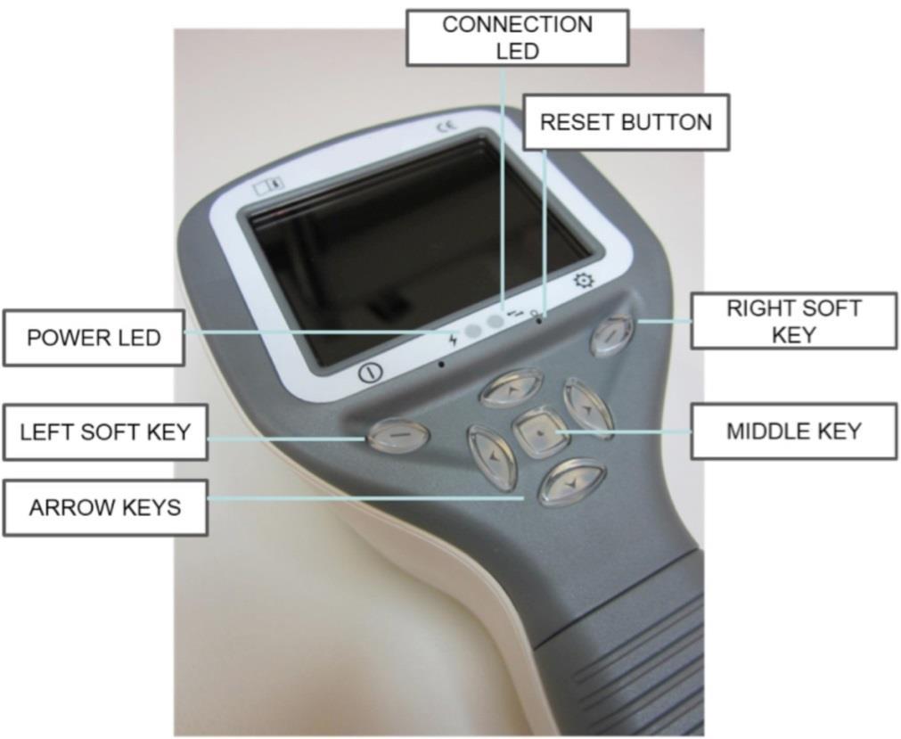
4 PARTS OF THE DEVICE IM-080 Rev. A Page 4 of 16
 and blue (connection) LED-lights: Position Indicator Purpose Left LED-indicator Green Active when device is powered on, blinking when charging")

5 Soft key indicators: Position Indicator Purpose To power on the device Left soft key To power off the device, with long press Right soft key Open menu with long press LED indicators: The recharging and connection to PC is indicated with green (charging) and blue (connection) LED-lights: Position Indicator Purpose Left LED-indicator Green Active when device is powered on, blinking when charging in cradle. Right LED-indicator Blue Active when device is placed to the cradle and connected to a PC. ATTACHING AND DETACHING OPTICS MODULE CAUTION: Optic modules used with Volk Optical Pictor Plus must include text PICTOR PLUS or PICTOR. It is not allowed to attach other objects to the bayonet connector. Optics are attached by placing it in front of the bayonet area of the device. Three bayonet legs are placed on the holes and optics is pressed firmly to the device. Optics are released by sliding release button that is located in front of the device above the dual action shutter. IM-080 Rev. A Page 5 of 16
, fundus angiography (FA), anterior eye imaging (ANT), ear imaging (OTO), skin imaging (DER), and general imaging (DF).")
6 DEVICE MENU - Menu is opened by pressing right soft key for 1s. - Menu has six tabs. One is for device settings such as language selection. There is one tab for retinal imaging (RET), fundus angiography (FA), anterior eye imaging (ANT), ear imaging (OTO), skin imaging (DER), and general imaging (DF). - Arrow keys are used to move between tabs: use arrow key up until tab is active and use left and right arrow keys to change active tab. Light blue color indicates active tab. - Arrow keys change values in the menu. Active value is indicated with light blue color. Changed values are saved by using left soft key ( Ok ) and cancelled by pressing right soft key ( Cancel ). Some values are confirmed by pressing the Middle key. Fluorescein Angiography Imaging Using Optic Modules VP2HAND & VP2FA The Volk Optical FA digital ophthalmic camera is intended to capture digital images of the fundus angiography of the human eye. The device set for fundus angiography imaging consists of: Pictor Plus handset VP2HAND Attachable Pictor Plus FA module VP2FA Eye cup for Pictor Plus VP2ECUP Cradle for charging and image transfer VPCRADLE Infrared is used for targeting image to the eye fundus and blue light is flashed when image is taken. Pupil does not respond to the infrared light so examination is convenient for the patient. Pictor Plus FA has 9 internal fixation targets for the patient to fixate at while imaging. Below section will guide how to control the fixation lights. STEPS FOR RETINAL IMAGING: 1. The examination room should be as dark as possible. 2. Both the patient and the examiner shall be seated while taking the images. 3. When using Pictor Plus FA optics, the device should be mounted on a slit lamp base using Slit lamp Adapter, its mandatory to achieve good images. 4. Either autofocus or manual focus can be used. Autofocus range is -11 to +3 diopters; manual focus range is - 20 to +20 diopters. If patient has a refractive error and autofocus is off, focus need to be adjusted: Hyperopia: camera is focused to distance by pressing arrow key up. One click of the key is approximately 2 Diopters. Myopia: camera is focused closer by pressing arrow key down. One click of the key is approximately 2 Diopters. 5. Aiming light is automatically turned on when camera enters live view. 6. The middle fixation target is lit when pressing left soft key and it provides a macula centred image. To change the fixation target press Left Soft Key and use arrow keys to navigate between the 9 targets as shown in the graphics in lower left corner of the display. If fixation target is turned off ask patient to look at a target in a wall 6-9 feet (2-3 meters) behind the operator. IM-080 Rev. A Page 6 of 16

7 7. Light is adjusted using left and right arrow key. There are altogether 10 brightness levels. Default value is 5. Suitable illumination is typically 2 to 8. Changing illumination brightness affects only the blue capturing flash. 8. Aim help square on the screen guides user when to take image. When retina is not fully in view the square is red. Once the aim is good and retina fully appears on screen the Square turn s green indicating a good moment for capturing the image. 9. Approaching the eye is started from 4 inches (10 centimetres) distance. Pupil is approached until the reflection from the eye fundus can be seen. The right imaging distance is about 0.8 inch (2 cm). Silicone support must be compressed approximately half way down. Aim help square on the display guides to take image once it turns from red to green. Camera is stabilised by keeping the outer side of the hand against the patient s forehead. Example of the correct usage position is shown below: 10. Still image is captured by pressing the shutter key all the way down. Video is captured by keeping shutter down. Taken image is displayed on screen until user clears the image by pressing shutter, left or right soft key. Image can be zoomed in instant preview by pressing middle key. There are four zoom levels. Pressing middle key activates the next level. Move around the image by using arrow keys. This Instant Preview can be enabled/ disabled in the Pictor Plus FA optics menu. 11. If multiple patients are examined during one session, new file folder is created for each patient by pressing middle key for over 3 seconds. 12. Transfer images to a PC after capturing images. Images are transferred to the PC when camera is placed to the cradle. Pictor Plus works as any other digital camera. 13. When camera is removed from the cradle it verifies image data storage erase. It is recommended that image data storage is always erased before images are captured of a new patient. IM-080 Rev. A Page 7 of 16


8 The camera keys function as shown in image below when VP2FA optics module is attached: Below table provides explanations for the key functions: Key Press Function Explanation Left soft key Short Control Fixation target level and selection Fixation target is off by default and can be turned on by pressing left soft key. Fixation target light has two levels: Low and High. If the patient cannot see the light on low level turn it up to high. Long Power On / Off Camera is powered on and off by pressing the Left soft key for longer than 2s. Right soft key Short Manual / Auto Switch between focus modes by pressing Right soft key. Manual focus is on by default. Autofocus range is -11 to +3 diopters, manual focus range is -20 to +20 diopters. Long Open Menu Enter camera menu by pressing Right soft key for longer than 1s. Middle key Long New patient folder If multiple patients are examined during a same session, it is recommended to create a new file folder for each patient s images. New folder is created by pressing middle key for 3 seconds. Icon P at the top of the screen indicates number of the current patient folder. If the current folder does not have any images in it, a new folder cannot be created. Change brightness Use left and right arrow keys to adjust capture light brightness. Icon above left soft key must be selected (lighter color) to change Left/Right arrow - brightness. Select fixation target Move between 9 internal fixation targets. Icon above left soft key turns to lighter color when fixation target selection mode is active. Focus manually When manual focus is active use up and down arrow keys to Up/Down arrow - focus. Press arrow key up when patient has myopia. Press arrow key down when patient has hyperopia. Select fixation target Move between 9 internal fixation targets. Icon above left soft key turns to lighter color when fixation target selection mode is active. IM-080 Rev. A Page 8 of 16
9 Table below includes explanations of the FA settings tab for fundus Angiography imaging: Setting Values (default bolded) Purpose Start Study This enables the study to start. For every new study, user needs to go into the menu and start study to enable the study or Time counter. Mark side On/Off Mark side of the eye to the image data. IR brightness Low/High Aiming light brightness. Instant Review On/Off Instant review can be ON/OFF according to user need, as available in FA Optics menu. Target Blinking On/Off By default the fixation target light is on with constant illumination. If patient cannot keep their eye targeted well the light can changed to blink to help focus on the target light. Calibration Frequency (5,10, user) User can manually set calibration frequency of the optics. Start Study This enables the study to start. For every new study, user needs to go into the menu and start study to enable the study or Time counter. Marking side It is possible to mark which eye was imaged. Marking side is enabled from the menu. When On side is marked to the file name and to the image. For video files, side is always marked only to the file name. When marking side is enabled, camera verifies side after each captured image. Identifiers used for eye images are OS for left and OD for right. IR Brightness IR brightness values are Low/Med/High. This can be chosen by user by using left and right arrow keys. Always high is recommended. Instant review Instant review can be ON/OFF according to user need, as available in FA Optics menu. Target blinking By default the fixation target light is on with constant illumination. If patient cannot keep their eye targeted well the light can changed to blink to help focus on the target light. Calibration Frequency User can manually set calibration frequency of the optics. For Example User selects 5, the device won t calibrate until next five consecutive images taken. Camera stores selected menu settings when it is powered off. IM-080 Rev. A Page 9 of 16
10 Menu: 1. Default Display window when FA optics is attached using Manual Mode. You can adjust the Diopter scale according to patient diopter manually. Image can be taken when shutter button held all the way down. 2. op:fa Optics recognized as FA for fundus angiography imaging. 3. Default Display window when FA optics is attached using AF Assist mode. Diopter scale is automatically adjusted, Image can be captured when shutter button is pressed half a way. 4. Default Display window when FA optics is attached using MF Assist mode. Diopter scale is manually adjusted, Image can be captured when shutter button is pressed half a way. IM-080 Rev. A Page 10 of 16

11 5. When Right Arrow key is held down all the way, Menu table appears on display. Default Device tab will be ON. By using left and right arrow keys you slide to the next tab. Here FA tab is chosen. Time Counter: Start study is selected from the FA optics menu. After pressing shutter button half way for one time during the live view screen. Time counter will appear on the upper right (pointed with arrow on the image). Time counter will be printed on the final images. Time counter will guide you through out through the all phases of Angiography. To stop the time counter after finishing the study, user need to switch to FA optics menu and press the STOP STUDY button. IM-080 Rev. A Page 11 of 16

12 TECHNICAL DESCRIPTION FUNDUS ANGIOGRAPHY MODULE CONNECTED TO THE PICTOR PLUS M5 CAMERA Type: Intended use: Illumination: Maximum Luminance output 8.07 cd/cm 2 level towards eye: Field of view: Diopter compensation: Image resolution: Dimensions: Weight: Pictor Plus FA Intended to capture digital images of the fundus angiograms of the human eye. Infrared LED for targeting Blue LED for photographing, 10 illumination brightness levels 9 red internal fixation target LEDs 40⁰ - 20 D to + 20 D 1536x1152 px (total 1.8 Mpix, informational area 1.41 Mpix) 160x73mm 310 g ENVIRONMENTAL CONDITIONS FOR USE, STORAGE, AND TRANSPORTATION: IP Code: IPX0 (Equipment not protected against the ingress of water) Use environment: Intended to be use indoors Temperature, use: + 10 C to 35 C Relative humidity, use: 10 % to 80 % Atmospheric pressure: 800 hpa to 1060 hpa NOTE: EMC information given in Annex A. Temperature, storage - 10 C to 40 C Relative humidity, storage: 10 % to 95 % Atmospheric pressure: 500 hpa to 1060 hpa NOTE: If stored over 1 month, it is recommended to remove battery. Transported in protective aluminium carrying case: Temperature: - 40 C to + 70 C Relative humidity: 10 % to 95 % Atmospheric pressure: 500 hpa to 1060 hpa Sinusoidal vibration: 10 Hz to 500 Hz: 0,5 g Shock: 30 g, duration 6 ms Bump: 10 g, duration 6 ms CONTACT If you wish to contact your local support personnel please call to: or us at: service@volk Optical.com WARRANTY Volk Optical gives device a 1 year warranty for the parts and labor. Warranty for battery is 6 months. Submitting claim: Any claim under this warranty must be submitted in writing before the end of warranty period to Volk Optical. The claim must include a written description of the failure that the device have. Warranty does not cover: Products that have been subjected to abuse, accident, alternation, modification, tampering, misuse, faulty installation, lack of reasonable care, repair or service in any way that is not contemplated in the documentation of the product, or if the model or serial number has been altered, tampered with, defaced or removed. Warranty does not cover damage caused by dropping the device or damage caused by normal wearing. Any issue related to the stickers attached to the device coming off are not covered by warranty. Repair or service done by non Volk Optical certified service facility is not covered by warranty. For customer support, contact: service@volk.com IM-080 Rev. A Page 12 of 16
13 Appendix A - Electromagnetic compatibility information MEDICAL ELECTRICAL SYSTEM needs special precautions regarding EMC and needs to be installed and put into service according to the EMC information provided. Portable and mobile RF communications equipment can affect MEDICAL ELECTRICAL SYSTEM. Pictor Plus should not be used adjacent to or stacked with other equipment and that if adjacent or stacked use is necessary, the EQUIPMENT or SYSTEM should be observed to verify normal operation in the configuration in which it will be used. Manufacturer s declaration electromagnetic immunity: PICTOR PLUS is intended for use in the electromagnetic environment specified below. The customer or the user of the Pictor Plus should assure that it is used in such an environment. Immunity test IEC test level Compliance level Electrostatic discharge (ESD) ±6 kv contact ± 2 kv, ± 4 kv, ± IEC ±8 kv air 6 kv indirect contact ± 2 kv, ± 4 kv, ± 6 kv contact ± 2 kv, ± 4 kv, ± 8 kv air Electrical fast transient/burst IEC Surge IEC Voltage dips, short interruptions and voltage variations on power supply input lines IEC Power frequency (50/60 Hz) magnetic field IEC ±2 kv for power supply lines ±1 kv for input/output lines ±1 kv line(s) to line(s) ±2 kv line(s) to earth <5 % U T (>95 % dip in U T ) for 0,5 cycle 40 % U T (60 % dip in U T ) for 5 cycles 70 % U T (30 % dip in U T ) for 25 cycles <5 % U T (>95 % dip in U T ) for 5 sec ±2 kv for AC power supply ±1 kv for serial cable ± 1 kv for AC power supply, 1 Phase without Protective Earth Manufacturer s test shows conformance to the requirements of the IEC /EN Electromagnetic environment guidance Floors should be wood, concrete or ceramic tile. If floors are covered with synthetic material, the relative humidity should be at least 30 %. Mains power quality should be that of a typical commercial or hospital environment. Mains power quality should be that of a typical commercial or hospital environment. Mains power quality should be that of a typical commercial or hospital environment. If the user of the Pictor Plus requires continued operation during power mains interruptions, it is recommended that the Pictor Plus be powered from an uninterruptible power supply or a battery. 3 A/m 3 A/m Power frequency magnetic fields should be at levels characteristic of a typical location in a typical commercial or hospital environment. NOTE U T is the a.c. mains voltage prior to application of the test level. IM-080 Rev. A Page 13 of 16
14 Guidance and manufacturer s declaration electromagnetic immunity: The Pictor Plus is intended for use in the electromagnetic environment specified below. The customer or the user of the Pictor Plus should assure that it is used in such an environment. Immunity test IEC test level Compliance level Electromagnetic environment guidance Portable and mobile RF communications equipment should be used no closer to any part of the Pictor Plus, including cables, than the recommended separation distance calculated from the equation applicable to the frequency of the transmitter. Recommended separation distance Conducted RF IEC Vrms 150 khz to 80 MHz 3 Vrms d = 1.2 d = MHz to 800 MHz d = MHz to 2.5 GHz where P is the maximum output power rating of the transmitter in watts (W) according to the transmitter manufacturer and d is the recommended separation distance in metres (m). Radiated RF IEC V/m 80 MHz to 2.5 GHz 3 V/M Field strengths from fixed RF transmitters, as determined by an electromagnetic site survey, a should be less than the compliance level in each frequency range. Interference may occur in the vicinity of equipment marked with the following symbol: NOTE 1 At 80 MHz and 800 MHz, the higher frequency range applies. NOTE 2 These guidelines may not apply in all situations. Electromagnetic propagation is affected by absorption and reflection from structures, objects and people. a) Field strengths from fixed transmitters, such as base stations for radio (cellular/cordless) telephones and land mobile radios, amateur radio, AM and FM radio broadcast and TV broadcast cannot be predicted theoretically with accuracy. To assess the electromagnetic environment due to fixed RF transmitters, an electromagnetic site survey should be considered. If the measured field strength in the location in which the Pictor Plus is used exceeds the applicable RF compliance level above, the Model 006 should be observed to verify normal operation. If abnormal performance is observed, additional measures may be necessary, such as re-orienting or relocating the Pictor Plus. b) Over the frequency range 150 khz to 80 MHz, field strengths should be less than 3 V/m. IM-080 Rev. A Page 14 of 16
15 Manufacturer s declaration electromagnetic emissions: PICTOR PLUS is intended for use in the electromagnetic environment specified below. The customer or the user of the Pictor Plus should assure that it is used in such an environment. Compliance Emissions test level Electromagnetic environment guidance RF emissions CISPR 11 Group 1 Uses RF energy only for its internal function. Therefore, its RF emissions are very low and are not likely to cause any interference in nearby electronic equipment. RF emissions CISPR 11 Harmonic emissions IEC Voltage fluctuations/ flicker emissions IEC Class B Not applicable Complies Is suitable for use in all establishments, including domestic establishments and those directly connected to the public low-voltage power supply network that supplies buildings used for domestic purposes. Recommended separation distances between portable and mobile RF communications equipment and the Volk Optical Pictor Plus: The Pictor Plus is intended for use in an electromagnetic environment in which radiated RF disturbances are controlled. The customer or the user of the Volk Optical Pictor Plus can help prevent electromagnetic interference by maintaining a minimum distance between portable and mobile RF communications equipment (transmitters) and the Volk Optical Pictor Plus as recommended below, according to the maximum output power of the communications equipment. Rated maximum output power of transmitter W Separation distance according to frequency of transmitter m 150 khz to 80 MHz d = khz to 80 MHz d = MHz to 2.5 GHz d = For transmitters rated at a maximum output power not listed above, the recommended separation distanced in metres (m) can be estimated using the equation applicable to the frequency of the transmitter, where P is the maximum output power rating of the transmitter in watts (W) according to the transmitter manufacturer. NOTE 1 At 80 MHz and 800 MHz, the separation distance for the higher frequency range applies. NOTE 2 These guidelines may not apply in all situations. Electromagnetic propagation is affected by absorption and reflection from structures, objects and people. IM-080 Rev. A Page 15 of 16


16 ORDERING INFORMATION Orders may be placed with the Authorized Volk Optical Distributor in your region. Authorized Distributor contact information is available directly from Volk Optical. Volk Optical Inc Enterprise Drive Mentor, Ohio USA Toll free within the United States: Phone: Fax: Website: EU REPRESENTATIVE The Volk authorized representative based in the European Union (EU) is: Keeler Limited Clewer Hill Road Windsor Berkshire SL4 4AA U.K. Tel: +44(0) Note: This product complies with current required standards for electromagnetic interferences and should not present problems to other equipment or be affected by other devices. As a precaution, avoid using this device in close proximity to other equipment. Members of the European Union should contact their authorized Volk Distributor for disposal of this unit Certificate FM Copyright 2014 Volk Optical Inc. IM-080 Effective: July 9, 2014 Revision: A IM-080 Rev. A Page 16 of 16
Powered Traction Unit OPERATION MANUAL
 Powered Traction Unit OPERATION MANUAL CONTENTS Symbols Safety precautions Symbol for CAUTION Symbol for CONSULT INSTRUCTIONS FOR USE Symbol for SERIAL NUMBER Symbol for CATALOGUE NUMBER Symbol for AUTHORISED
BIODEX MULTI- JOINT SYSTEM
 BIODEX MULTI- JOINT SYSTEM CONFORMANCE TO STANDARDS 850-000, 840-000, 852-000 FN: 18-139 5/18 Contact information Manufactured by: Biodex Medical Systems, Inc. 20 Ramsey Road, Shirley, New York, 11967-4704
English
 English Specifications Type Power Source Vibration Frequency Maximum Output Power Consumption Water Pressure Lighting NE134 AC120V 50/60Hz AC230V 50/60Hz 28~32kHz 8W Max. 42VA 0.1~0.5MPa (1~5kgf/cm
Guidance and Declaration - Electromagnetic Compatibility (EMC) for the Delfi PTS ii Portable Tourniquet System
 for the Delfi PTS ii Portable Tourniquet System") Guidance and Declaration - Electromagnetic Compatibility (EMC) for the Delfi TS ii ortable Tourniquet System Guidance and manufacturer s declaration electromagnetic emissions The TS ii ortable Tourniquet
Guidance and Declaration - Electromagnetic Compatibility (EMC) for the Delfi TS ii ortable Tourniquet System Guidance and manufacturer s declaration electromagnetic emissions The TS ii ortable Tourniquet
HeRO duet
 HeRO duet CUSTOMER SERVICE TABLE OF CONTENTS TABLE OF CONTENTS OVERVIEW OVERVIEW OVERVIEW OVERVIEW USING HeRO duet USING HeRO duet USING HeRO duet Current HeRO Score HeRO USING HeRO duet USING HeRO duet
D C 01/2019 3
 D-0117968-C 01/2019 3 4 D-0117968-C 01/2019 Screw Driver Screw Driver Unplug both the Red & Blue connectors. (see above) Place a small flat head screw driver on the small orange tabs and push down while
Electromagnetic compatibility Guidance and manufacturer s declaration DIN EN :2007 (IEC :2007)
") Compressor set Equipment Under Test (EUT) Type 028 Type 047 Type 052 Type 085 Electromagnetic compatibility Guidance and manufacturer s declaration DIN EN 60601-1-2:2007 (IEC 60601-1-2:2007) 2017 PARI
Compressor set Equipment Under Test (EUT) Type 028 Type 047 Type 052 Type 085 Electromagnetic compatibility Guidance and manufacturer s declaration DIN EN 60601-1-2:2007 (IEC 60601-1-2:2007) 2017 PARI
General Safety/EMC and Electrical Information for i-limb ultra and i-limb digits
 1. General Safety 1.1 The i-limb ultra and i-limb digits devices are electrical devices, which under certain circumstances could present an electrical shock hazard to the user. Please read the accompanying
Nursing Beds with Dewert drive system
 Nursing Beds with Dewert drive system GB Casa Med Classic 4 / Classic (FS) Casa Med Ultra / Ultra (FS) Casa Med Classic Low Casa Med Classic (FS) 4 / Classic / Casa FS Med / Casa Classic Med Low Ultra
Technical Specifications Micromedical VisualEyes 505 by Interacoustics
 VisualEyes 505 - Technical Specifications Page 0 Technical Specifications Micromedical VisualEyes 505 by Interacoustics D-0115523-B 2018/02 VisualEyes 505 - Technical Specifications Page 1 Included and
PHYSIOFLOW Q-LINK TM
 PHYSIOFLOW Q-LINK TM Service Manual Thursday, 20 October 2016 First placing on the market : 18 January 2012 User Manual PhysioFlow Q-Link 1/17 Table of contents 1. General Information... 3 About this manual...
OtoRead - Technical Specifications Page 0. Technical Specifications. OtoRead D A 2017/06
 OtoRead - Technical Specifications Page 0 Technical Specifications OtoRead D-0116698-A 2017/06 OtoRead - Technical Specifications Page 1 OtoRead TM Configuration Overview The OtoReadTM is available in
Biological Safety. Electromagnetic Compatibility (EMC) Observe the following precautions related to biological safety.
 Observe the following precautions related to biological safety.") Biological Safety Observe the following precautions related to biological safety. WARNING: Non-medical (commercial) grade peripheral monitors have not been verified or validated by SonoSite as being suitable
Biological Safety Observe the following precautions related to biological safety. WARNING: Non-medical (commercial) grade peripheral monitors have not been verified or validated by SonoSite as being suitable
MedRx Avant Polar HIT AH-I-MPHITS-5 Effective 11/07/11
 INSTALLATION MANUAL 2 Contents Getting To Know Your AVANT POLAR HIT TM... 4 Setting up the System... 6 Software Installation... 7 Driver Installation Windows 7... 10 Driver Installation Windows XP... 13
USER MANUAL MHS-2500I. Please take time to read these instructions before starting to use the scale. Version /17
 USER MANUAL MHS-2500I Please take time to read these instructions before starting to use the scale Version 1.0 05/17 Contents Introduction 3 Product Specification 3 Safety Instructions 4 Explanation of
TH008F Multi-function Infrared Forehead Thermometer
 TH008F Multi-function Infrared Forehead Thermometer Specifications Functions Temperature measurement range: Forehead mode: 34~42.2 C (93.2~108 F), Surface mode: -22~80 C (-7.6~176 F) Operating temperature
(c) Medisave UK. Notice. Edition 1. i-pad Operator s Manual
 Medisave UK. Notice. Edition 1. i-pad Operator s Manual") Edition 1 Notice i-pad Operator s Manual CU Medical Systems, Inc. reserves the right to make changes on the device specifications contained in this manual at any time without prior notice or obligation
Edition 1 Notice i-pad Operator s Manual CU Medical Systems, Inc. reserves the right to make changes on the device specifications contained in this manual at any time without prior notice or obligation
VN415/VO425 Specifications
 VN415/VO425 Specifications Item No. 8105231-1 01/2014 Contents VN415 Specifications... 1 1.1 Technical Standards:...1 1.2 System Requirements:...1 1.3 Included and Optional Parts...2 VO425 Specifications...
Rolyan Splint Pan OPERATION MANUAL. Item # Small Item # Large
 Rolyan Splint Pan OPERATION MANUAL Item #081544816 - Small Item #081544808 Large PLEASE READ THIS ENTIRE MANUAL BEFORE OPERATING YOUR NEW SPLINT PAN. Failure to follow these instructions could result in
USER MANUAL M-200. Please take time to read these instructions before starting to use the scale. Version /06
 USER MANUAL M-200 Please take time to read these instructions before starting to use the scale Version 1.0 07/06 Contents Introduction 3 Product Specification 3 Safety Instructions 4 Explanation of Graphic
#
 INSTALLATION MANUAL 2 Contents Getting To Know Your AVANT POLAR HIT TM... 4 Setting up the System... 6 Software Installation... 7 Driver Installation Windows 7... 10 Driver Installation Windows XP... 13
DENTAL X-RAY OPERATOR'S INSTRUCTIONS. (for USA) Wall Mount Type...WK
 Wall Mount Type...WK") M 505 DENTAL X-RAY OPERATOR'S INSTRUCTIONS (for USA) Wall Mount Type...WK WARNING This X-ray equipment may be dangerous to patient and operator unless safe exposure factors, operating instructions and
M 505 DENTAL X-RAY OPERATOR'S INSTRUCTIONS (for USA) Wall Mount Type...WK WARNING This X-ray equipment may be dangerous to patient and operator unless safe exposure factors, operating instructions and
User Instruction Computer Assisted Local Analgesia. 337 Marion, Le Gardeur QC, Canada, J5Z 4W8
 User Instruction Computer Assisted Local Analgesia 1-800-667-9622 337 Marion, Le Gardeur QC, Canada, J5Z 4W8 USER INSTRUCTION Congratulations on your new CALAJECT! Please read these instructions thoroughly
Technical Data. Electrocardiograph ECG-1250K TD.ECG1250_L. This technical data may be revised or replaced by Nihon Kohden at any time without notice.
 Technical Data Electrocardiograph ECG-1250K This technical data may be revised or replaced by Nihon Kohden at any time without notice. TD.ECG1250_L Specifications ECG input Input impedance: 20 MΩ Electrode
M-400 M-410 M-420 M-430
 USER MANUAL M-400 M-410 M-420 M-430 Please take time to read these instructions before starting to use the scale Version 1.1 10/17 Contents Introduction 3 Product Specification 3 Safety Instructions 4
Not for print. Microphone Test Device with SONNET MTD Adapter. User Manual. Cochlear Implants NOT FOR PRINT
 Cochlear Implants Microphone Test Device with SONNET MTD Adapter User Manual AW32690_1.0 (English) Table of contents 1. Table of contents 2. INTRODUCTION 3 Product description 3 3. INTENDED USE INDICATIONS
INSTALLATION MANUAL AVANT HIT+ Hearing Instrument Test Chamber.
 INSTALLATION MANUAL AVANT Hearing Instrument Test Chamber HIT+ www.medrx-int.com Contents Getting To Know Your AVANT HIT+. 3 Computer Requirements 4 Setup System. 5 Software Installation.. 6 Sound Card
Operating Manual Infrared thermometer
 Operating Manual Infrared thermometer Model:IT-121 Professional Fast Accurate 1 CONTENTS 1 I n t r o d u c t i o n................ 3 1.1Product intended use 3 2 Basic principle 3 3 Pr o d u c t f e a t
INTRODUCTION. 4 SAFETY INSTRUCTIONS. 5 ABOUT THIS DEVICE. 6 FIRST OPERATION. 7 THE DISPLAY. 8 ATTACHING THE WRIST SLEEVE. 9 CORRECT MEASUREMENT.
 Table of contents INTRODUCTION.............................. 4 SAFETY INSTRUCTIONS........................ 5 ABOUT THIS DEVICE.......................... 6 FIRST OPERATION............................ 7
SAVI SCOUT Surgical Guidance System. Console Operation Manual
 SAVI SCOUT Surgical Guidance System Console Operation Manual 2 Copyrights and Trademarks 2016 Cianna Medical, Inc. All rights reserved. Patents pending. Cianna Medical and SAVI are registered trademarks
: 0089 GTIN
 GTIN: 00894912002050 PRECAUTIONS PROBE Non-invasive probes are for transcutaneous use only Probe transducer tips are thin and delicate. Be careful not to drop or hit the probe tip. After use, protect the
The following symbol indicates that the device is MR-unsafe:
 The following symbol indicates that the device is MR-unsafe: MR Unsafe Do not use this equipment In the MRI scan room Patient must follow the doctor s instructions and should not perform a self-assessment
WRIST BLOOD PRESSURE MONITOR
 WRIST BLOOD PRESSURE MONITOR Instruction Manual MODEL: ABP801 www.accumed.com TABLE OF CONTENTS INTRODUCTION... 1 NOTES ON SAFETY... 1 ABOUT BLOOD PRESSURE... 3 PRECAUTIONS BEFORE US... 4 FEATURES OF THE
#0086.
 INSTALLATION MANUAL Contents Getting to Know Your AVANT REM Speech+... 3 Software Installation... 4 Driver Installation Windows 7... 7 EMC Precautions... 11 Safety... 15 Limited Warranty... 18 #0086 www.medrx-usa.com
The following languages can be found on our website: French. German. Spanish. Italian. Swedish. Portuguese. Russian. Dutch.
 Manufactured By: 5580 S. Nogales Hwy. Tucson, Az 85706 USA Telephone: 800-975-7987 Fax: 520-294-6061 www.westmedinc.com PN 74586, Rev. 10 MT Promedt Consulting GmbH Altenhofstr. 80 66386 St. Ingbert, Germany
SJM MRI Activator. Handheld Device. User's Manual. Model EX4000
 SJM MRI Activator Handheld Device User's Manual Model EX4000 Unless otherwise noted, indicates that the name is a trademark of, or licensed to, St. Jude Medical or one of its subsidiaries. ST. JUDE MEDICAL
Ceiling Model Ceiling Model for LEDview Plus and Heliodent Plus. Installation Requirements. New as of: English
 New as of: 03.2017 Ceiling Model Ceiling Model for LEDview Plus and Heliodent Plus Installation Requirements English Installation Requirements Ceiling Version = Dentsply Sirona Installation Requirements
OPERATOR'S INSTRUCTIONS DX-073 DENTAL X-RAY
 DENTAL X-RAY DX-073 Wall Mount Type...WK Ceiling Mount Type...CK Floor Mount Type...FK1/2 Mobil Mount Type...FM Room Mount Type...RKII OPERATOR'S INSTRUCTIONS 0197 WARNING : This X-ray equipment may be
Multi-Control Panel for built-in system. Multi Pad for NLX / imd OPERATION MANUAL OM-E0538E 001
 Multi-Control Panel for built-in system Multi Pad for NLX / imd OPERATION MANUAL OM-E0538E 001 Thank you for purchasing Multi Pad. Read this Operation Manual carefully before use for operation instructions
OPERATOR'S INSTRUCTIONS DENTAL X-RAY MODEL 096
 DENTAL X-RAY MODEL 096 OPERATOR'S INSTRUCTIONS 0197 WARNING: This X-ray equipment may be dangerous to patients and operators unless safe exposure factors and operating instructions are observed. R Table
Wide Angle Ophthalmoscope Instructions
 Wide Angle Ophthalmoscope Instructions PLEASE READ AND FOLLOW THESE INSTRUCTIONS CAREFULLY Contents 1. Symbols 2. Warnings & Cautions 3. Description of Product 4. Getting Started 5. Apertures & Filters
HD STETH TM Quick Start User Guide
 Thank you and for choosing the futuristic HD Steth TM manufactured by HD Medical Inc. USA Indications for Use (IFU) HD Steth is an electronic stethoscope meant to assist a qualified clinician to capture,
GTIN:
 GTIN: 00894912002920 TABLE OF CONTENTS Introduction...1 Features...1 Indications for Use...1 Contraindications...1 Warnings & Precautions...2 Controls...3 Operation...4 Recharging the Battery...5 Replacing
INSTRUCTIONS FOR YOUR NEW PLASMAFLOW. Vascular Therapy System (Compressible Limb Sleeve Device)
") INSTRUCTIONS FOR YOUR NEW PLASMAFLOW Vascular Therapy System (Compressible Limb Sleeve Device) Customer Service Toll Free: 888-508-0712 Email: CustomerService@manamed.net Web: www.manamed.net 1511 W. Alton
INSTRUCTIONS FOR YOUR NEW PLASMAFLOW Vascular Therapy System (Compressible Limb Sleeve Device) Customer Service Toll Free: 888-508-0712 Email: CustomerService@manamed.net Web: www.manamed.net 1511 W. Alton
Welch Allyn Home Scale (T- RPM-SCALE100)
") Welch Allyn Home Scale (T- RPM-SCALE100) Directions for use 901077 Weight scale, Software Version 1.0 2017 Welch Allyn. All rights are reserved. To support the intended use of the product described in
Welch Allyn Home Scale (T- RPM-SCALE100) Directions for use 901077 Weight scale, Software Version 1.0 2017 Welch Allyn. All rights are reserved. To support the intended use of the product described in
This product may malfunction due to electromagnetic waves caused by portable
 1 IMPORTANT NOTICE This product may malfunction due to electromagnetic waves caused by portable personal telephones, transceivers, radio-controlled toys, etc. Be sure to avoid having objects such as, which
Transmitter Model EX1100, EX1100W. User's Manual
 Merlin@home Transmitter Model EX1100, EX1100W User's Manual Unless otherwise noted, indicates that the name is a trademark of, or licensed to, St. Jude Medical or one of its subsidiaries. ST. JUDE MEDICAL
Central Blood Pressure Meter Model cbp301. Operating Manual
 Central Blood Pressure Meter Model cbp301 Operating Manual Document cbp301-009 Issue 4 September 2011 Contents Introduction... 3 Package Contents... 5 Warnings and Cautions... 6 Contraindications... 7
L NKTEMP. Non-contact. Infrared Thermometer. User Manual LMP001
 L NKTEMP Non-contact Infrared Thermometer User Manual LMP001 TABLE OF CONTENTS Product Description Intended Use Product Features Safety Precautions Using the Thermometer Taking a Measurement Temperature
Operator s Manual External Remote Controller (ERC)
") OM0000-C, 2010-07 Page 1 of 25 Table of Contents 1. SYMBOLS DEFINITION:...3 2. PRODUCT WARNINGS:...6 3. PRODUCT DESCRIPTION:...8 4. COMPONENT IDENTIFICATION:...8 5. INSTRUCTIONS FOR USE:...9 6. EMERGENCY
OM0000-C, 2010-07 Page 1 of 25 Table of Contents 1. SYMBOLS DEFINITION:...3 2. PRODUCT WARNINGS:...6 3. PRODUCT DESCRIPTION:...8 4. COMPONENT IDENTIFICATION:...8 5. INSTRUCTIONS FOR USE:...9 6. EMERGENCY
The Symbol means that the Vet-Tech (200, 250 or 300HF) system intentionally applies some radioelectric energy for diagnostic or treatment purposes.
 system intentionally applies some radioelectric energy for diagnostic or treatment purposes.") IDENTIFICATION The Vet Tech X-ay unit is available with 3 powers: see the box below Denomination 200HF 250HF 300 HF Usual name Vet Tech 200HF Vet Tech 250HF Vet Tech 300HF Power 12 kw 20 kw 30 kw Milli
IDENTIFICATION The Vet Tech X-ay unit is available with 3 powers: see the box below Denomination 200HF 250HF 300 HF Usual name Vet Tech 200HF Vet Tech 250HF Vet Tech 300HF Power 12 kw 20 kw 30 kw Milli
`bob`=p=^åèìáëáíáçå=råáí
 `bob`=p=^åèìáëáíáçå=råáí qéåüåáå~ä=a~í~= båöäáëü The new CEREC 3 generation for the computer-aided manufacture of ceramic restorations. CAD system for making high-precision optical impressions in the mouth.
Rotating Anode X-Ray Tube Housing Assembly. General Data
 Technical Data TD ROTANODE E7252X E7252FX E7252GX 0197 Rotating Anode X-Ray Tube Housing Assembly High speed rotating anode X-ray tube housing assembly for high energy radiographic and cine-fluoroscopic
`bob`=p=^åèìáëáíáçå=råáí=bma
 `bob`=p=^åèìáëáíáçå=råáí=bma qéåüåáå~ä=a~í~= båöäáëü The new CEREC 3 generation for the computer-aided manufacture of ceramic restorations. CAD system for making high-precision optical impressions in the
Osmolarity System USER MANUAL FOR QUANTITATIVE MEASUREMENT OF OSMOLARITY OF OCULAR TISSUES. osdcare.com
 Osmolarity System FOR QUANTITATIVE MEASUREMENT OF OSMOLARITY OF OCULAR TISSUES USER MANUAL osdcare.com I-PEN User Guide I-PEN User Guide TABLE OF CONTENTS I-PEN I-PEN is a trademark of I-MED Pharma Inc.
ENG en. Operating instructions. Iris Magneton MF Wellness therapy
 ENG en Operating instructions Iris Magneton MF Wellness therapy Edition 09 / 2012 These operating instructions constitute an accessory of the device. They must therefore be kept in a suitable place near
OPERATOR S INSTRUCTIONS (for USA & Canada)
") MODEL 097 DENTAL X-RAY OPERATOR S INSTRUCTIONS (for USA & Canada) WARNING This X-ray equipment may be dangerous to patients and operators unless safe exposure factors and operating instructions are observed.
MODEL 097 DENTAL X-RAY OPERATOR S INSTRUCTIONS (for USA & Canada) WARNING This X-ray equipment may be dangerous to patients and operators unless safe exposure factors and operating instructions are observed.
POCKET AIR. Portable Nebulizer. Instruction Manual MBPN002 / MB / MB05006
 R POCKET AIR Portable Nebulizer Instruction Manual MBPN002 / MB0500300/ MB05006 Table of Contents General information... 1 Intended Use... 2 Safety Precautions... 3 Explanation of Symbols... 4 Package
SPAC265-8W. AC-DC power supply module. Features. Description. Applications
 AC-DC power supply module Datasheet production data Features Open frame switch mode power supply European input voltage range Single output 5 V, 8 W peak power, 4 W continuous operating mode EMC compliance
AUTOMATIC BLOOD PRESSURE MONITOR (Arm Cuff Type) INSTRUCTION MANUAL
 INSTRUCTION MANUAL") AUTOMATIC BLOOD PRESSURE MONITOR (Arm Cuff Type) INSTRUCTION MANUAL Model: SPBP-04 English Instruction Guide Thank you for choosing Advocate as your monitor of choice. The first, most important part of
AUTOMATIC BLOOD PRESSURE MONITOR (Arm Cuff Type) INSTRUCTION MANUAL Model: SPBP-04 English Instruction Guide Thank you for choosing Advocate as your monitor of choice. The first, most important part of
IEC Second Edition
 Electromagnetic Compatibility of Medical Electrical Equipment Second Edition Prepared by Mr. James Conrad Presented by Dr. William A. Radasky 1 Second Edition Updates first edition on standards developed
ibed Locator Model 5212
 ibed Locator Model 5212 Connected Hospital Instructions for Use and Installation For Parts or Technical Assistance: USA: 1-800-327-0770 2011/03 5212-009-101 REV C www.stryker.com Table of Contents Symbols
H2 Check Operating Manual
 H2 Check Operating Manual Federal (USA) law restricts this device to sale by or on the order of a physician or licensed practitioner. Micro Direct, Inc. 803 Webster Street Lewiston, ME 04240 1-800-588-3381
OPERATOR S MANUAL AN APPLIED DIGITAL COMPANY
 OPERATOR S MANUAL AN APPLIED DIGITAL COMPANY Contents: VeriChip H2 Reader Assembly Part Number 600-000515-000 (includes all of the following): USER INSTRUCTIONS Description Part Number Description The
How to use the Barcode Scanner:
 How to use the Barcode Scanner: Please click on [TwMCA-App] icon shown on Desktop. Then click it to execute Barcode scanner software. Then select [Decode ON] button on the application software to turn
Instructions for use. Back. Next. Home
 Instructions for use Home Back Next Contents 1. Introduction 2. Symbols 3. Indications for use 4. Intended use / purpose of instrument 5. Brief description of the instrument 6. Safety 7. Cleaning and disinfection
Relief. At Last. User Manual For an effective treatment, read the entire User Manual before using Kyrobak.
 Relief. At Last. User Manual For an effective treatment, read the entire User Manual before using Kyrobak. Contents Know Your Kyrobak 2 Safety Instructions 3 Before You Start 4 How to Use Kyrobak 5 Operating
Nerve stimulator TWISTER
 Nerve stimulator TWISTER INSTRUCTIONS FOR USE Softwareversion 1.19 Manufacturer: Dr. Langer Medical GmbH Fabrik Sonntag, Haus 4a 79183 Waldkirch Germany Table of contents 1 Intended use... 5 2 Common
TEST REPORT... 1 CONTENT...
 CONTENT TEST REPORT... 1 CONTENT... 2 1 TEST RESULTS SUMMARY... 3 2 EMC RESULTS CONCLUSION... 4 3 LABORATORY MEASUREMENTS... 6 4 EMI TEST... 7 4.1 CONTINUOUS CONDUCTED DISTURBANCE VOLTAGE TEST... 7 4.2
ENGLISH. Important safety information Read this important information carefully before you use the device and save it for future reference.
 SCH740 EN www.philips.com/avent Philips Consumer Lifestyle BV Tussendiepen 4, 9206 AD Drachten, Netherlands Trademarks owned by the Philips Group. 2017 Koninklijke Philips N.V. All rights reserved Find
2620 Modular Measurement and Control System
 European Union (EU) Council Directive 89/336/EEC Electromagnetic Compatibility (EMC) Test Report 2620 Modular Measurement and Control System Sensoray March 31, 2006 April 4, 2006 Tests Conducted by: ElectroMagnetic
REVISION
 Refa User Manual 92-0121-0001-0-3 REVISION 3 2017 0344 TABLE OF CONTENTS 1 SERVICE AND SUPPORT 4 1.1 About this manual 4 1.2 Contact information TMSi 4 1.3 Warranty information 4 2 SAFETY INFORMATION
TM Machine WetAlert TM Wireless Wetness Detector In-center User s Guide
 2008K@home TM Machine WetAlert TM Wireless Wetness Detector In-center User s Guide 2008K@home WetAlert Wireless Wetness Detector In-Center User s Guide Copyright 2012-2014, 2016, Fresenius USA, Inc. All
2015 Koninklijke Philips N.V. All rights reserved Philips Consumer Lifestyle BV Tussendiepen 4, 9206AD Drachten, Netherlands
 SCH740 2015 Koninklijke Philips N.V. All rights reserved Philips Consumer Lifestyle BV Tussendiepen 4, 9206AD Drachten, Netherlands 4213.354.3816.3 (11/2015) >75% recycled paper >75% papier recyclé 2 3
Draft. User s Manual. Transmitter Model EX1150
 User s Manual Merlin @home Transmitter Model EX1150 CAUTION Federal (USA) law restricts this device to sale by or on the order of a physician. 2008 St. Jude Medical Cardiac Rhythm Management Division.
User instructions for the ABI-system 100
 User instructions for the ABI-system 100 0124 User instructions for the ABI-system 100 1 ABI-system 100 2 CA04 cuffs (for upper arms) 2 CL04 cuffs (for legs) 1 ABI software CD 1 USB cable 1 boso mains
Transcutaneous Electrical Nerve Stimulator
 Transcutaneous Electrical Nerve Stimulator Simple, effective pain relief *For the temporary relief of pain as part of current medication programme. Distributor Medi-Direct International Ltd. Unit 24, Wilford
MINISCAV Vacuum Pump Manual
 MINISCAV Vacuum Pump Manual North American Model Caution: Federal law restricts this device to sale by or on the order of a physician or dentist. MR Unsafe - Do not place or use Miniscav in or near an
AeroDR Stitching System
 DIRECT DIGITIZER Operation Manual AeroDR Stitching System EN 06 Contents Introduction................. 5 Introduction.............................. 6 Summary of usability specifications (for IEC/EN 60601-1-6,
BodyclockStimplusManual.qx8_Layout 1 17/08/ :53 Page 1. Body Clock Stimplus. Instructions for use
 BodyclockStimplusManual.qx8_Layout 1 17/08/2012 11:53 Page 1 Body Clock Stimplus TM Instructions for use BodyclockStimplusManual.qx8_Layout 1 17/08/2012 11:53 Page 2 Acupuncture is an ancient Chinese therapy
Product Name: COMPER SMART DOPPLER FETAL MONITOR. Product Model: DFMX
 DFMX User Manual Document Num: History of Change: User Manual JS02114DFMX V1.0 Issue Date: Version: Editor: Reviewer: Approver: Date:xx-xx-xx Date:xx-xx-xx Date:xx-xx-xx Product Name: COMPER SMART DOPPLER
Exergen TAT 5000S RS232 TTL Supplemental Instructions for Use
 www.exergen.com/s Exergen TAT 5000S RS232 TTL Supplemental Instructions for Use For additional specifications, see GE Healthcare CARESCAPE V100 Vital Signs Monitor Operator's Manual, Section 12. Symbol
Product Manual N.2 WEARABLE ECG. PRODUCT MANUAL
 Product Manual WEARABLE ECG www.vitaljacket.com www.biodevices.pt Biodevices S.A. Av. D. Afonso Henriques, 1462 1º Traseiras 4450-013 Matosinhos Portugal N.2 O NOVO NORTE PROGRAMA OPERACIONAL REGIONAL
User Manual. Before Using Your WiTouch Pro Device
 User Manual Before Using Your WiTouch Pro Device Sync the Remote Control and the WiTouch Pro Device. Using the provided screwdriver, remove the back cover from the WiTouch Pro device. 2. Remove the clear
DIGITAL BLUETOOTH THEROMETER PBT
 DIGITAL BLUETOOTH THEROMETER PBT Index 1. 2. 3. 4. 5. 6. 7. 8. 9. 10. 11. 12. 13. 14. 15. Introduction Important Information Before Use Product Identification Description of LCD Display Battery Installation
IDEAL INDUSTRIES, INC. TECHNICAL MANUAL MODEL:
 IDEAL INDUSTRIES, INC. TECHNICAL MANUAL MODEL: 61-352 The Service Information provides the following information: Precautions and safety information Specifications Basic maintenance (cleaning, replacing
WELCOME WHAT S IN THE BOX
 WELCOME Congratulations on purchasing your Visioneer PaperPort flatbed scanner. With your scanner, you can quickly scan paper documents and color photos to place their electronic images on your computer.
By Paul Aylett at 12:08 pm, Apr 13, 2016
 TD2 Series Content Introduction Parts Features General Warnings and Safety Using your TENS Pain Reliever Troubleshooting Positions for use Specification Compatibility EMC Maintenance and Cautions Explanation
Doc. EA Model Number:
 VPS-030AAC Series / VPS-030AAC 030AAC Highlights & Features VPS-030AAC05, 12, 15, 24 Meet DOE Level VI & ErP 2017 Low touch current. Suitable for type BF applications Detachable AC plug with multiple country
CardioMessenger II-S Transmitter for BIOTRONIK Home Monitoring. Technical Manual
 CardioMessenger II-S Transmitter for BIOTRONIK Home Monitoring 362454_D_GA_CM_II-S_US.indd 1 Technical Manual 17.04.08 16:28:16 by BIOTRONIK GmbH & Co. KG All rights reserved. Specifications subject to
Model Microphone Preamplifier Power Supply Manual
 Model 2221 Microphone Preamplifier Power Supply Manual Larson Davis Model 2221 Microphone Preamplifier Power Supply Manual I2221.01 Rev H Copyright Copyright 2009-2015 by PCB Piezotronics, Inc. This manual
Introducing the Pixium Portable System
 Introducing the Pixium Portable System. Congratulations on your purchase of the Pixium Portable system. The Pixium Portable is a mobile radiography system that converts static radiographic images into
Connevans.info. DeafEquipment.co.uk. This product may be purchased from Connevans Limited secure online store at
 Connevans.info Solutions to improve the quality of life Offering you choice Helping you choose This product may be purchased from Connevans Limited secure online store at www.deafequipment.co.uk DeafEquipment.co.uk
User instructions. boso ABI-system 100
 User instructions boso ABI-system 100 0124 Contents 1 Contents of package 4 2 Minimum system requirements 4 3 Explanation of symbols and operating controls 5 4 Explanation of icons 6 5 Preliminary remarks
Instruction Manual. Questions? Call ADC toll free: Otoscope. Coax Ophthalmoscope. Dermascope. Throat Illuminator.
 Instruction Manual Otoscope Coax Ophthalmoscope Dermascope Throat Illuminator Power Handles Questions? Call ADC toll free: 1-800-232-2670 Diagnostix TM Otoscope Diagnostix TM Coax Ophthalmoscope Diagnostix
Kinder products for your most precious patients
 Kinder products for your most precious patients Keeler kinder products Keeler is a global leader in the supply and design of ophthalmic diagnostic products. Our products are used throughout the world to
TETRIS 1000 High Impedance Active Probe. Instruction Manual
 TETRIS 1000 High Impedance Active Probe Instruction Manual Copyright 2015 PMK GmbH All rights reserved. Information in this publication supersedes that in all previously published material. Specifications
Certificate of Test AND KEEPS ALL REQUIREMENTS ACCORDING THE FOLLOWING REGULATIONS IEC :2001 IEC :2007
 Certificate of Test WE HEREBY CERTIFY THAT: Certificate No.: R07122709E Yuan Hsun Electric Co., Ltd. No. 57, Chung He Rd, Zuo-Ying Dist., Kaohsiung City 813, Taiwan R.O.C. Quad photobeam detector Quad-200CS
CDR Wireless / SDX Software User Guide
 CDR Wireless / SDX Software User Guide Schick Technologies, Inc. 30-00 47 th Avenue Long Island City, NY 11101 (718) 937-5765 (718) 937-5962 (fax) PART NUMBER B1051503 REV. Copyright 2004 by Schick Technologies,
EMC TEST REPORT For MPP SOLAR INC Inverter/ Charger Model Number : PIP 4048HS
 EMC-E20130903E EMC TEST REPORT For MPP SOLAR INC Inverter/ Charger Model Number : PIP 4048HS Prepared for : MPP SOLAR INC Address : 4F, NO. 50-1, SECTION 1, HSIN-SHENG S. RD. TAIPEI, TAIWAN Prepared by