SEM Training Notebook
|
|
|
- Elinor Violet Copeland
- 5 years ago
- Views:
Transcription
1 SEM Training Notebook Lab Manager: Dr. Perry Cheung MSE Fee-For-Service Facility Materials Science and Engineering University of California, Riverside March 8, 2018 (rev. 3.5) 1
2 Before you begin Complete the required safety training modules on UC Learning Laboratory Safety Orientation (Fundamentals) 2013 Hazardous Waste Management Compressed Gas Safety X-Ray Safety Submit a copy of your Training Transcript to Lab Manager Review the MSE SEM Policies and Regulations Fill out the SEM FAU Authorization Form with PI signature Fill out the MSE 150, 250, 309 Authorization Form with PI signature Receive a user name and temporary password for Faces scheduling Arrange a time for SEM training with Lab Manager Schedule a 2 hour block on Faces for your training Familiarize yourself with the graphical user interface (GUI) :A D Familiarize yourself with SEM fundamentals: E K 2


3 A. GUI Menu Bar Floating Toolbar SEM Scanning Window Focus Window Side Bar Info Bar 3
4 B. Floating Toolbar 1/2 MODE: Opens the context menu for selecting Displaying Modes SPEED: Opens the context menu for selecting predefined Scan Speeds MAG: Left-click sets the Magnification as active function. Right-click opens context menu with predefined values of magnification. WD: Left-click sets the Focus as active function. STG: Left-click sets the Stigmator as active function. 4
5 B. Floating Toolbar 2/2 Brightness: Left-click sets the Brightness and Contrast control as active function Auto: Left-click starts Automatic Brightness and Contrast BI: Left-click sets the Beam Intensity as active function Manual Column Centering: Left-click starts the manual column centering process Acquire: Left-click starts the Image Acquisition 5

6 C. Sidebar 1/5 Opens new scanning window Opens up IR Camera Indicates Active Function Current value(s) of Active Function Incremental changes of Active Function Changes Sensitivity of Increment buttons and Trackball 1 = Fine, 9 = Course Flashing Trackball Icon Current value = Trackball is locked of Sensitivity 6
7 C. Sidebar 2/5 Info Panel shows all the important parameters of the microscope, and at the same time allows a quick set-up of all the most frequently used functions. o Continual button stops or starts scanning o Single button starts scanning of a single frame and then stops scanning o Acquire button starts the acquisition process o HV button sets the High Voltage value as active function o Depth of Focus shows estimated range sample surface is in focus o Absorb. Curr. shows the electron current absorbed by the sample o Spot Size shows the sample impinging beam size 7

8 C. Sidebar 3/5 Detector Panel shows active detector. Electron Beam Panel controls filament heating and high voltage range. o SE indicates Secondary Electron detector is active o %/% shows Brightness/Contrast o HV shows high voltage value o Emission shows current emitted o Live Time shows total working time of filament o Heating shows relative value of filament heating current in % HV turns the high voltage on and off Heat starts or stops filament heating Adjustment opens context menu HV Drop Down selects HV range 8
9 C. Sidebar 4/5 Vacuum Panel controls the vacuum system. PUMP starts the pumping procedure (~ 3 min to complete) VENT vents the microscope o Column Pressure indicates the value of the pressure in the column o Red = Not Ready o Green = Ready o Status shows state of vacuum o Venting = still venting o Venting finished = venting is finished and chamber can be opened o Pumping = still pumping o Vacuum ready = chamber is pumped down to sufficient vacuum o Vacuum off = vacuum is in standby mode STANDBY interrupts microscope work if necessary for a long period of time 9
10 C. Sidebar 5/5 Nano Stage Control controls the specimen stage movement. If missing, find in Menu under SEM > Nano Stage Control Rotation buttons rotate the stage Diagonal stage movement X-dir stage movement Y-dir stage movement Distance from center is proportional to magnitude of movement (large) 10

11 D. SEM Image Parameters Windows Aspect Ratio of Image = 4:3 Resolution = 1024 x 768 Averaging Accumulation = Disable (Prone to vibrational noise and drift) 5 5 Acquisition Keep Actual Speed Keep view field/print magnification Infobar Texts Show Infobar: Beam Energy, Working Distance, View Field, Detector, Vacuum, Scan Mode 11


12 E. Accelerating Voltage 1/2 30 kv Recommendation: Start at 5 kv and increase voltage incrementally to balance resolution to surface structures 5 kv 12


13 E. Accelerating Voltage 2/2 250 V 500 V 1 kv 5 kv 10 kv 20 kv


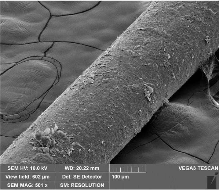
14 F. Working Distance WD = 10 mm Recommendation: Start at 10 mm and decrease WD to achieve greater resolution or increase WD to achieve greater depth of field if necessary WD = 20 mm 14
15 G. Working Distance vs Focus (W/D) Distance Objective Pole Piece Focus (W/D) Distance Focus (W/D) Distance Actual Working Distance Over Focus In Focus Under Focus Actual Working Distance = Distance between objective pole piece and sample and can only be controlled manually with the knob outside the chamber Focus (W/D) Distance = Distance between objective pole piece and focal point and can only be controlled by the Focus (W/D) button 15


16 H. Beam Intensity 1/3 BI = 15 Recommendation: Decrease beam intensity until balance between resolution/grainy image and acquisition time is desired High BI: Larger spot size for low magnification but poor resolution Beam Intensity Low BI: Higher resolution but grainier image, need to balance with slower scan SPEED BI = 4 16
 BI = 15 Speed = 1 BI = 10 Speed = 1 BI = 6 Speed = 1 BI")


17 H. Beam Intensity 2/3 Low Magnification (Minimum < Mag < 10 kx) BI = 15 Speed = 1 BI = 10 Speed = 1 BI = 6 Speed = 1 BI = 6 Speed = 7 At Low Mag, lowering BI doesn t have a dramatic affect on the quality of image High Magnification (10 kx < Mag < Maximum) BI = 15 Speed = 1 BI = 10 Speed = 1 BI = 6 Speed = 1 BI = 6 Speed = 7 At High Mag, the BI MUST be chosen correctly! A grainy image will ALWAYS accompany a reduction in BI, but is easily removed with a drop in scan SPEED!


18 I. SEM Chamber Z-dir Stage Movement Knob Coarse Control Stage Tilt Handle Z-dir Stage Movement Knob Fine Control 0 Tilt Position Tilt Position Marker 18


 15")


19 J. Tilt (Advanced Users) - 1/2 0 Tilt (Flat) 15 Tilt 30 Tilt


20 J. Tilt (Advanced Users) - 2/2 45 Tilt 60 Tilt 70 Tilt
21 K. High Resolution Imaging Process Tree # Description Stage Mag Focus 1 Center tallest part of tallest sample in window Z Knob BI Speed Auto B/C Yes Yes Yes Yes Yes Yes 2 Achieve desired working distance Yes Yes Yes Yes Yes 3 Center desired sample image in window with desired Mag Yes Yes Yes Yes Yes Yes 4 Increase Mag to 2X desired Mag Yes Yes Yes Yes Yes 5 Beam optimization (if desired Mag 10 kx) Yes Yes Yes Yes 6 Achieve best focus Yes Yes Yes Yes 7 Reduce Mag back to desired Mag Yes Yes Yes Yes 8 Determine optimal image conditions for BI and Speed and acquire Yes Yes Yes 9 Reduce Mag and acquire image Yes Yes Yes Yes 10 Move to new sample location -> Repeat #3 to #9 21
22 SEM Operation I. Initiate Software II. Sample Preparation III. Sample Loading IV. Turning on HV V. Mode VI. Beam Intensity VII. Brightness and Contrast VIII. Mag IX. Focusing X. Speed XI. Working Distance XII. Image Preparation XIII. Column Centering XIV. Stigmation Correction XV. Image Acquisition XVI. Saving XVII. Sample Unloading XVIII. Cleanup 22


23 I. Initiate Software 1/1 1. Record your time-in on the sign-in sheet located on preparation table 2. Sign into Windows using provided Username and Password located on monitor if necessary 3. Double-click on VegaTC icon to load software 4. Sign into your user account with your Username and Password 23
 3.")
24 II. Sample Preparation 1/1 1. Always wear gloves when dealing with anything that will be placed into or in contact with the SEM 2. The specimen should be conductively fixed or glued to a specimen stub (12.5 mm specimen pin-stubs) 3. Non-conductive samples need to be coated by a conductive layer using either a carbon coater or sputter coater (coming soon to MSE) 4. Magnetic samples will need to be fixed well by screw holder (provided by user) 5. Items located in the cabinet are available for SEM users to help prepare their samples
25 III. Sample Loading 1/3 1. Click VENT to vent the microscope 2. Click Yes to confirm venting 3. Wait until Venting finished appears 4. Set the tilt of the specimen stage to 0 if not already set to 0 (Advanced Users only) 5. Gently pull the chamber corners toward you to open the chamber 25

 9.")
26 III. Sample Loading 2/3 6. Rotate stage if necessary to access screw port 7. Using provided tweezers, clamp onto the specimen stub and blow a stream of air over the entire specimen stub AWAY from the chamber using Airgun 8. Loosen the screw first (see example) 9. Carefully insert the specimen stub into the specimen stage 10.Tighten the screw holding the specimen stub 26

27 III. Sample Loading 3/3 11. Ensure that the sample stage is at the lowest position using Z-knob (clockwise) 12. Carefully close the chamber door by pushing it towards the chamber CHECKING THAT THE SAMPLE DOES NOT TOUCH ANYTHING INSIDE CHAMBER 13. Place finger against chamber door 14. Click PUMP to start pumping down chamber 15. Wait until bar graph shows red to release finger 16. Wait until the bar graph turns green or Vacuum ready appears (~ 3 min) 27
 3. Click HV to turn on the high voltage 4.")
28 IV. Turning on HV 1/2 1. Click on HV on the Info Panel or select HV in Pad Drop Down High Voltage 5.00 k V 2. Set a specific High Voltage in the Pad panel (set 5 kv as starting voltage) 3. Click HV to turn on the high voltage 4. Click Adjustment >>> and select Auto Gun Heating (required if black screen present AFTER turning on HV)


29 V. Mode 1/1 1. Click MODE 2. Confirm Continual Wide Field option is checked 3. Choose desired scanning mode (default = Resolution) A B C Mode Resolution Depth Field Characteristics High resolution Lower depth of focus Good resolution Increased depth of focus Lower resolution Large field of view High depth of focus D Wide Field Extra large field of view A C B D 4. Right-click on MAG and select Minimum Magnification 29

30 VI. Beam Intensity 1/1 1. Center the SEM window onto your desired sample using the stage control 2. Click BI to adjust beam intensity using the << and >> Recommended Initial BI values BI = 15 Speed = 1 3. Recommend BI of 15 to start at low mag 4. Change the sensitivity if necessary Recommended Value = 3 BI = 6 Speed = 1 BI = 10 Speed = 1

31 VII. Brightness and Contrast 1/1 1. Click Auto to auto adjust the brightness and contrast if too bright or dark as necessary 2. Click Brightness to manually adjust the brightness and contrast Contrast: Hold F12 + trackball = Change only Contrast Brightness: Hold F11 + trackball = Change only Brightness 3. Click on the IR Camera button to open up the view of the chamber (if you haven t already)
32 VIII. Mag 1/1 1. Click MAG to change the magnification 2. Turn the trackball from left to right 3. Or enter a value directly in Pad panel Change the sensitivity if necessary 32 Recommended Value = 5
 and 5 for Coarse (Mag 10kX) 5.")
33 IX. Focusing 1/1 1. Click WD to adjust focus distance 2. Turn the Trackball from left to right to adjust focus 3. A focused image shows the actual working distance via WD value 4. Change the sensitivity if necessary Recommended Value = 2 for Fine (Mag 10kX) and 5 for Coarse (Mag 10kX) 5. Double-left-click in the SEM scanning window to create a Focus Window Left mouse button inside = move Focus Window Right mouse button inside = resize Focus Window Double-left-click = remove Focus Window 6. WD 30 mm when sample is at lowest position
34 X. Speed 1/1 1. Click SPEED to adjust scan speed 2. Use Focus Window to determine the effect of SPEED and BI has on your image quality Recommendation: SPEED of 1 4 for initial focusing BI setting should be appropriate to MAG value SPEED Acquisition Time sec sec sec 4 3 sec 5 16 sec 6 32 sec 7 1 min 36 sec 8 4 min 34 sec 9 13 min 58 sec min 4 sec Recommended Initial BI values SPEED of higher values looks better but takes longer to focus! Use higher SPEED values of 5 8 when ready to save images 34
35 XI. Working Distance 1/3 Use combination of MAG, Stage Control, and focusing (WD) to first: a. Identify and bring the tallest position of your tallest sample to the center of SEM scanning window b. Increase MAG until distinct features make up majority of window c. Check if mode = Resolution or Depth (if not, keep increasing MAG) d. If you can t see transition between focus out-of-focus with WD, you skipped a step! NOTE: The tallest portion of the tallest sample should be focused since this will crash into the pole-piece first as you raise the stage in the next step. This DOES NOT have to be the desired position or sample for your images, it is ONLY for setting the safe working distance value! Desired Working Distance Correct Start Tallest Sample Tallest Position Safe Working Distance 35
36 XI. Working Distance 2/3 Wrong Sample + Wrong Position Wrong Sample + Correct Position CRASH!!! CRASH!!! Correct Sample + Wrong Position Correct Sample + Correct Position CRASH!!! SAFE!!!

37 XI. Working Distance 3/3 PROCEED WITH CAUTION AS CHANGING THE WORKING DISTANCE CAN RESULT IN DAMAGE TO THE SEM! 1. Identify current WD by focusing on sample 2. Raise the specimen stage by SLOWLY turning the Z-knob counter-clockwise WD WD WD 3. Identify new WD by focusing on sample 4. Repeat steps 2-3 until desired WD is achieved 5. Click Auto to auto adjust the brightness and contrast if too dark when necessary In Focus Under Focus 6. SLOW DOWN WHEN YOU REACH ~ 10 mm AND DO NOT GET LESS THAN 5 mm 4 In Focus 37


38 XII. Image Preparation 1/2 Imaging at MAG 10 kx requires optimization steps XIII. Column Centering and XIV. Stigmation Correction after completion of XII. Image Preparation, else skip and proceed next to XV. Image Acquisition directly Example 1. Right-click on MAG and select Minimum Magnification to see your whole sample again 2. Identify an area of interest on your sample to image by using a combination of MAG, Stage Control, focusing (WD), and BI 38
 20 kx Higher MAG yields better results but gets more difficult to optimize 5.")
39 XII. Image Preparation 2/2 3. Bring the area of interest to the center of SEM scanning window and to the highest desired magnification (e.g. Desired Mag = 10 kx) 10 kx Example You will NOT use the Stage Control after this step, so ENSURE that the image at the Desired Mag is the one you wish to take before continuing 4. Increase MAG by 2X the desired Mag using the Pad (e.g. New Mag = 20 kx, 30 kx, etc ) 20 kx Higher MAG yields better results but gets more difficult to optimize 5. Reduce BI if necessary to increase resolution 6. Change scan SPEED to 3 or 4 to remove graininess 7. Focus (WD) your sample again Recommended Initial BI values 39


40 XIII. Column Centering 1/3 1. Create a Focus Window around a feature of interest 2. Click WD and bring the feature into focus 3. If image moves or shifts as you focus, then column centering needs to be completed and continue to Step 5 4. If image does not move or shift, proceed to XIV. Stigmation Correction Column Centered Under-focused Focused Over-focused 5. Click Manual Column Centering button 6. The Manual Centering Wizard will appear 7. Click Next>>

41 XIII. Column Centering 2/3 8. Your image will now wobble in and out of focus If image has any X or Y translation as it wobbles, you will need to remove it 9. Minimize image movement by adjusting the OBJ Centering using the trackball X: Hold F12 + trackball = Change only X-movement Y: Hold F11 + trackball = Change only Y-movement 41


42 XIII. Column Centering 3/3 8. The image should remain stationary with no X or Y translation but only oscillate in/out of focus 9. Adjust the sensitivity to finely control the OBJ Centering if necessary Recommended Value = 5 first then If flashing trackpad is present, click << Previous and Next >> to reset 11. Adjust the Wobbler sensitivity to change the extent of wobble if necessary at very high magnifications 12. Click Finish when done
 to check if any streaking occurs on non-straight")

43 XIV. Stigmation Correction 1/4 1. Create a Focus Window on a feature of interest 2. Click WD and bring the feature in and out-of-focus (both sides) to check if any streaking occurs on non-straight features Stigmation Not Corrected Under-Focused Focused Over-Focused 3. Any streaks are evidence that Stigmation Correction is necessary 4. When Stigmation corrected, a focused image will become significantly sharper Stigmation Not Corrected Focused Stigmation Corrected Focused
44 XIV. Stigmation Correction 2/4 5. Set SPEED = 4 + appropriate BI (see table) 6. Click WD and create a Focus Window 7. Focus on a feature (WD Sensitivity = 2) as BEST AS YOU CAN Recommended Initial BI values 8. Click the STG to set as active function 9. Set STG Sensitivity = 6 (slow down trackball for accuracy near sweet spot ) 10. Achieve a sharper image by adjusting the Stigmators one at a time (X and Y) X: Hold F12 + trackball = Change the X-component Y: Hold F11 + trackball = Change only Y-component 11. CAREFULLY AND SLOWLY adjust each Stigmator component (X and Y) until you can identify the perfect or setting with the sharpest image 12. REPEAT Steps 6 11 until you no longer see any improvement in sharpness


45 XIV. Stigmation Correction 3/4 13. If your image still doesn t look good, 99% it s because of poor STG Correction 14. The sequence of STG Correction should resemble the following: Out-of-Focus 1 st Focus STG X STG Y 2 nd Focus STG X STG Y 3 rd Focus 15. Repeat the sequence as necessary until the image looks good

46 XIV. Stigmation Correction 3/4 16. Proper STG Correction is EXTREMELY sensitive 17. A few % values off from perfect setting, and your image will look very blurry! perfect 1% off 2% off 3% off 4% off 5% off 6% off 7% off 18. If this is the case, GO BACK AND RE-DO the STG Correction!
 20 kx")
 10 kx 3.")
47 XV. Image Acquisition 1/3 1. Create Focus Window and achieve the BEST focus (Recommend Sensitivity = 2) 20 kx Example (Do NOT focus again AFTER this step!) 2. Click MAG and set back to desired magnification (e.g. Desired Mag = 10 kx) 10 kx 3. Activate the Focus Window over a desired feature Smaller window = requires less time to refresh
48 XV. Image Acquisition 2/3 4. Identify maximum Acquisition Time for your image (e.g. 2 min) and select corresponding Speed (e.g. SPEED = 7) 5. Adjust the BI until a balance between resolution is matched with graininess 6. Click Auto to auto adjust the brightness and contrast as you change the BI SPEED Acquisition Time sec sec sec 4 3 sec 5 16 sec 6 32 sec 7 1 min 36 sec 8 4 min 34 sec 9 13 min 58 sec min 4 sec NOTE: Remove focus window first else it will only adjust pixels found within focus window + change speed back to 1 for faster auto correction 7. If high resolution is desired but excessive graininess is present, increase the Acquisition Time (e.g. SPEED = 7 -> 8) 8. Repeat Steps 5 6 until desired balance between resolution and graininess and is achieved (e.g. see next slide for examples)


49 XV. Image Acquisition 3/3 Low Resolution Low Graininess BI High Resolution High Graininess Speed 8 49


50 XVI. Saving 1/1 1. Click Acquire to capture image 2. If desired, you may save information to the image file Note = the basic description Sign = the enlarged description Description = the detailed information Add = saves the Note or Sign in the list Delete = deletes the Note or Sign from the list 3. If you choose not to include any Header information, click OK 4. Choose the folder location for your images 5. Enter your file name 6. Click Save 50
51 XVII. Sample Unloading 1/3 1. Right-click on MAG and select Minimum Magnification 2. Click SPEED and select SPEED 1 3. Carefully lower the sample stage to the lowest position by turning the Z-knob clockwise 4. Set BI to Click Auto


52 XVII. Sample Unloading 2/3 6. Set WD to 30 mm Click HV to turn off the high voltage 8. Click VENT to vent the microscope 9. Click Yes to confirm venting 10. Wait until Venting finished appears 11. Set the tilt of the specimen stage back to 0 if not already set to 0 (Advanced Users only) 52


53 XVII. Sample Unloading 3/3 12. Gently pull the chamber corners toward you to open the chamber 13. Loosen the screw holding the specimen stub on the specimen stage 14. Rotate the stage if necessary to access screw port 15. Using the provided tweezers, carefully remove the specimen stub out of the specimen stage

54 XVIII. Cleanup 1/1 1. Ensure that the sample stage is at the lowest position by full clockwise turns 2. Carefully close the chamber door by pushing it towards the chamber 3. Place finger against chamber door 4. Click PUMP to start pumping down chamber 5. Wait until bar graph shows red to release finger 6. Wait until the bar graph turns green or Vacuum ready appears (~ 3 min) 7. Open the File menu and select Logoff, click Yes 8. Record your total time used in the Sign-in sheet 54
SEM Training Notebook
 SEM Training Notebook Lab Manager: Dr. Perry Cheung MSE Fee-For-Service Facility Materials Science and Engineering University of California, Riverside December 21, 2017 (rev. 3.4) 1 Before you begin Complete
Standard Operating Procedure for the Amray 1810 Scanning Electron Microscope Version: 29 NOVEMBER 2014
 Standard Operating Procedure for the Amray 1810 Scanning Electron Microscope Version: 29 NOVEMBER 2014 1. Utility Requirements a. System power is supplied by two 120 VAC/20 A circuits. When doing maintenance
Basic Operating Instructions for Strata Dual Beam 235 FIB/SEM
 Basic Operating Instructions for Strata Dual Beam 235 FIB/SEM Warning Always adjust your specimen height before closing the chamber door to make sure your specimen will not hit the bottom of the lens;
JEOL 6700 User Manual 05/18/2009
 JEOL 6700 User Manual 05/18/2009 LOG IN to your session on the computer to the right of the microscope. Starting Conditions 1. Click the button and read the Penning Gauge to ensure that the microscope
JEOL 6500 User Manual
 LOG IN to your session on the computer to the left of the microscope. Starting Conditions 1. Press Ctrl-Alt-Del and log on to the microscope computer. Click on JEOL PC SEM 6500 icon. Click yes if message
Scanning Electron Microscope FEI INSPECT F50. Step by step operation manual
 Scanning Electron Microscope FEI INSPECT F50 Step by step operation manual Scanning Electron Microscope, FEI Inspect F50 FE-SEM-F Observation Flow Saving Data And Analysis Specimen preparation Error check
FE-SEM SU-8020 Operating manual (Preliminary version)
") FE-SEM SU-8020 Operating manual (Preliminary version) 2016/04/11 Seimitsu Bunseki sitsu lab. Starting up 1.Turn on the Display switch. Windows OS is starting up 2. Select the user SU-8000. 3. Click the
FE-SEM SU-8020 Operating manual (Preliminary version) 2016/04/11 Seimitsu Bunseki sitsu lab. Starting up 1.Turn on the Display switch. Windows OS is starting up 2. Select the user SU-8000. 3. Click the
OPERATION OF THE HITACHI S-450 SCANNING ELECTRON MICROSCOPE. by Doug Bray Department of Biological Sciences University of Lethbridge
 OPERATION OF THE HITACHI S-450 SCANNING ELECTRON MICROSCOPE by Doug Bray Department of Biological Sciences University of Lethbridge Revised September, 2000 Note: The terms in bold in this document represent
Using the Hitachi 3400-N VP-SEM
 Using the Hitachi 3400-N VP-SEM Opening the Chamber to Load Specimens (This may also be done later using the software) 1. Click the AIR button on the front of the machine: 2. Wait a few minutes until you
Model SU3500 Scanning Electron Microscope
 Model SU3500 Scanning Electron Microscope Modified and Parts taken from Hitachi Easy Operation Guide. Before using the Model SU3500 SEM, be sure to read the [GENERAL SAFETY GUIDELINES] in the instruction
1.1. Log on to the TUMI system (you cannot proceed further until this is done).
.") FEI DB235 SEM mode operation Nicholas G. Rudawski ngr@ufl.edu (805) 252-4916 1. Sample loading 1.1. Log on to the TUMI system (you cannot proceed further until this is done). 1.2. The FIB software (xp)
FEI DB235 SEM mode operation Nicholas G. Rudawski ngr@ufl.edu (805) 252-4916 1. Sample loading 1.1. Log on to the TUMI system (you cannot proceed further until this is done). 1.2. The FIB software (xp)
JSM 6060 LV SCANNING ELECTRON MICROSCOPE STANDARD OPERATING PROCEDURES
 JSM 6060 LV SCANNING ELECTRON MICROSCOPE STANDARD OPERATING PROCEDURES RULES All users must go through a series of standard operation procedure training. For more information contact: Longlong Liao Teaching
RAITH e-line OPERATING INSTRUCTIONS
 RAITH e-line OPERATING INSTRUCTIONS 1) LOADING A SAMPLE a. Start the system i. On the Column PC (Right side monitor [R]), select the SmartSEM icon to on the desktop to begin the column software. ii. On
1. Preliminary sample preparation
 FEI Helios NanoLab 600 standard operating procedure Nicholas G. Rudawski ngr@ufl.edu (352) 392 3077 (office) (805) 252-4916 (cell) Last updated: 03/02/18 What this document provides: an overview of basic
Basic Users Manual for Tecnai-F20 TEM
 Basic Users Manual for Tecnai-F20 TEM NB: This document contains my personal notes on the operating procedure of the Tecnai F20 and may be used as a rough guide for those new to the microscope. It may
Title: Amray 1830 SEM#2 Semiconductor & Microsystems Fabrication Laboratory Revision: D Rev Date: 03/18/2016
 Approved by: Process Engineer / / / / Equipment Engineer 1 SCOPE The purpose of this document is to detail the use of the Amray 1830 SEM. All users are expected to have read and understood this document.
Operating Checklist for using the Scanning Electron. Microscope, JEOL JSM 6400.
 Smith College August 2009 Operating Checklist for using the Scanning Electron Microscope, JEOL JSM 6400. CONTENT, page no. Pre-Check 1 Startup 1 Specimen Insertion 2 Filament Saturation 2 Beam Alignment
User Operation of JEOL 1200 EX II
 **Log onto Computer** Open item program Start Up Procedure User Operation of JEOL 1200 EX II 1. If scope is not running, locate an electron microscopy technician (EMT) to find out why not. 2. Turn up brightness
Operating Checklist for using the Scanning Electron Microscope, JEOL JSM 6400.
 Smith College August 2005 Operating Checklist for using the Scanning Electron Microscope, JEOL JSM 6400. CONTENT, page no. Pre-Check, 1 Specimen Insertion, 1 Startup, 2 Filament Saturation, 2 Beam Alignment,
Operating the Hitachi 7100 Transmission Electron Microscope Electron Microscopy Core, University of Utah
 Operating the Hitachi 7100 Transmission Electron Microscope Electron Microscopy Core, University of Utah Follow the procedures below when you use the Hitachi 7100 TEM. Starting Session 1. Turn on the cold
MSE 595T Transmission Electron Microscopy. Laboratory III TEM Imaging - I
 MSE 595T Basic Transmission Electron Microscopy TEM Imaging - I Purpose The purpose of this lab is to: 1. Make fine adjustments to the microscope alignment 2. Obtain a diffraction pattern 3. Obtain an
SEM OPERATION IN LOW VACUUM MODE
 SEM OPERATION IN LOW VACUUM MODE Instructions for JEOL 5800 LV The EVAC light of the SEM specimen chamber should be already lit when you approach the SEM & the SEM will have been left in the high vacuum
Instructions for Tecnai a brief start up manual
 Instructions for Tecnai a brief start up manual Version 3.0, 8.12.2015 Manual of Tecnai 12 transmission electron microscope located at Aalto University's Nanomicroscopy Center. More information of Nanomicroscopy
Check that the pneumatic hose is disconnected!!!! (unless your using the BSE detector, of course)
") JEOL 7000F BASIC OPERATING INSTRUCTIONS-Ver.-2.0 Note: This is minimal operation checklist and does not replace the other reference manuals. Read the manual for Specimen Exchange (JEOL 7000 Specimen Exchange
JEOL 7000F BASIC OPERATING INSTRUCTIONS-Ver.-2.0 Note: This is minimal operation checklist and does not replace the other reference manuals. Read the manual for Specimen Exchange (JEOL 7000 Specimen Exchange
General information. If you see the instrument turned off, notify MIC personnel. MIC personnel will help you insert your samples into the instrument.
 JEOL JSM-7400F Table of contents General information.. 3 The operation panel. 4 The different sample holders and inserting the samples.. 5 Turning on the beam... 6 Stage map control... 8 Correcting astigmatism...
Dickinson College Department of Geology
 Dickinson College Department of Geology Title: Equipment: BASIC OPERATION OF THE SCANNING ELECTRON MICROSCOPE (SEM) JEOL JSM-5900 SCANNING ELECTRON MICROSCOPE Revision: 2.2 Effective Date: 1/29/2003 Author(s):
SOP for Hitachi S-2150 Scanning Electron Microscope For review purposes only
 SOP for Hitachi S-2150 Scanning Electron Microscope For review purposes only Version 1.0 Prepared by D. Turnbull February 21, 2007. Please submit any omissions to the Author Note: This SEM is a recent
ZEISS EVO SOP. May 2017 ELECTRON OPTICS
 ZEISS EVO SOP May 2017 ELECTRON OPTICS The patented EVO column is the area of the SEM, where electrons are emitted, accelerated, deflected, focused, and scanned. Main characteristics of the EVO optics
Full-screen mode Popup controls. Overview of the microscope user interface, TEM User Interface and TIA on the left and EDS on the right
 Quick Guide to Operating FEI Titan Themis G2 200 (S)TEM: TEM mode Susheng Tan Nanoscale Fabrication and Characterization Facility, University of Pittsburgh Office: M104/B01 Benedum Hall, 412-383-5978,
JEOL JEM-1400 Transmission Electron Microscope Operating Instructions
 JEOL JEM-1400 Transmission Electron Microscope Operating Instructions Anti-contamination device Objective aperture Objective aperture translation knobs Specimen holder Pump/air switch Left hand control
2. Raise HT to 200kVby following the procedure explained in 1.6.
 JEOL 2100 MANUAL Quick check list 1. If needed, fill the reservoir with LN2 2. Raise HT to 200kVby following the procedure explained in 1.6. 3. Insert specimen holder into TEM (Insert holder in airlock,
MSE 460 TEM Lab 2: Basic Alignment and Operation of Microscope
 MSE 460 TEM Lab 2: Basic Alignment and Operation of Microscope Last updated on 1/8/2018 Jinsong Wu, jinsong-wu@northwestern.edu Aims: The aim of this lab is to familiarize you with basic TEM alignment
Operating Procedures for MICROCT1 Nikon XTH 225 ST
 Operating Procedures for MICROCT1 Nikon XTH 225 ST Ensuring System is Ready (go through to ensure all windows and tasks below have been completed either by you or someone else prior to mounting and scanning
FEI Tecnai G 2 F20 Operating Procedures
 FEI Tecnai G 2 F20 Operating Procedures 1. Startup (1) Sign-up in the microscope log-sheet. Please ensure you have written an account number for billing. (2) Log in to the computer: Login to your account
FEI Quanta 200 ESEM Basic instructions
 FEI Quanta 200 ESEM Basic instructions Desktop and then start the UI. If the computer has restarted and you need to login, Username: supervisor and Password: supervisor Log-in to the Microscope using the
1.3. Before loading the holder into the TEM, make sure the X tilt is set to zero and the goniometer locked in place (this will make loading easier).
.") JEOL 200CX operating procedure Nicholas G. Rudawski ngr@ufl.edu (805) 252-4916 1. Specimen loading 1.1. Unlock the TUMI system. 1.2. Load specimen(s) into the holder. If using the double tilt holder, ensure
JEOL 200CX operating procedure Nicholas G. Rudawski ngr@ufl.edu (805) 252-4916 1. Specimen loading 1.1. Unlock the TUMI system. 1.2. Load specimen(s) into the holder. If using the double tilt holder, ensure
Please follow these instructions for use of the Philips CM100 TEM. Adopted from website below.
 Please follow these instructions for use of the Philips CM100 TEM. Adopted from website below. http://staff.washington.edu/wpchan/if/cm100_inst.shtml Instructions for the Philips CM100 TEM and peripherals
Scanning Electron Microscope. Instructions for Use
 Scanning Electron Microscope Instructions for Use The reproduction, transmission or use of this document or its contents is not permitted without express written authority. Offenders are liable for damages.
1.2. Make sure the viewing screen is covered (exposure to liquid N 2 may cause it to crack).
.") FEI Tecnai F20 S/TEM: imaging in TEM mode Nicholas G. Rudawski ngr@ufl.edu (805) 252-4916 (352) 392-3077 Last updated: 01/21/18 1. Filling the cold trap (if needed) 1.1. Prior to use, the cold trap needs
FEI Tecnai F20 S/TEM: imaging in TEM mode Nicholas G. Rudawski ngr@ufl.edu (805) 252-4916 (352) 392-3077 Last updated: 01/21/18 1. Filling the cold trap (if needed) 1.1. Prior to use, the cold trap needs
This procedure assumes the user is already familiar with basic operation of the SEM and the MiraTC interface.
 Tescan MIRA3 SEM: EDS using EDAX TEAM Nicholas G. Rudawski ngr@ufl.edu Cell: (805) 252-4916 Office: (352) 392-3077 Last updated: 12/04/17 This procedure assumes the user is already familiar with basic
Bruker Dimension Icon AFM Quick User s Guide
 Bruker Dimension Icon AFM Quick User s Guide March 3, 2015 GLA Contacts Jingjing Jiang (jjiang2@caltech.edu 626-616-6357) Xinghao Zhou (xzzhou@caltech.edu 626-375-0855) Bruker Tech Support (AFMSupport@bruker-nano.com
The ideal K-12 science microscope solution. User Guide. for use with the Nova5000
 The ideal K-12 science microscope solution User Guide for use with the Nova5000 NovaScope User Guide Information in this document is subject to change without notice. 2009 Fourier Systems Ltd. All rights
Figure 1 The Raith 150 TWO
 RAITH 150 TWO SOP Figure 1 The Raith 150 TWO LOCATION: Raith 150 TWO room, Lithography area, NanoFab PRIMARY TRAINER: SECONDARY TRAINER: 1. OVERVIEW The Raith 150 TWO is an ultra high resolution, low voltage
Nanoscale Fabrication & Characterization Facility. Raith e-line EBL Users Guide (updated:aug 2 nd, 2017)
") Nanoscale Fabrication & Characterization Facility Raith e-line EBL Users Guide (updated:aug 2 nd, 2017) Overview: The Raith e-line EBL system is designed to write features with critical dimensions as small
Nanoscale Fabrication & Characterization Facility Raith e-line EBL Users Guide (updated:aug 2 nd, 2017) Overview: The Raith e-line EBL system is designed to write features with critical dimensions as small
Bruker Dimension Icon AFM Quick User s Guide
 Bruker Dimension Icon AFM Quick User s Guide August 8 2014 GLA Contacts Jingjing Jiang (jjiang2@caltech.edu 626-616-6357) Xinghao Zhou (xzzhou@caltech.edu 626-375-0855) Bruker Tech Support (AFMSupport@bruker-nano.com
1. Specimen Holder Removal, Loading, and Insertion
 OPERATION OF THE PHILIPS CM-200 FEG-TEM When not in use, the CM-200 should be in the MICROSCOPE ON configuration with the HIGH TENSION ON (illuminates green when the high tension is on).. The microscope
COMPACT MANUAL FOR GI USERS OF THE JEM 1400 FLASH BEGINNERS (For internal use only) Gray means additional information at the end of this mini-manual
 Gray means additional information at the end of this mini-manual") 1 COMPACT MANUAL FOR GI USERS OF THE JEM 1400 FLASH BEGINNERS (For internal use only) Gray means additional information at the end of this mini-manual ABOUT THIS MICROSCOPE (room HG01.240) The JEM-1400Flash
1 COMPACT MANUAL FOR GI USERS OF THE JEM 1400 FLASH BEGINNERS (For internal use only) Gray means additional information at the end of this mini-manual ABOUT THIS MICROSCOPE (room HG01.240) The JEM-1400Flash
Standard Operating Procedure Hitachi UHR CFE SU8230 SEM
 Standard Operating Procedure Hitachi UHR CFE SU8230 Yale West Campus Materials Characterization Core ywcmatsci.yale.edu ESC II, Room E119F 810 West Campus Drive West Haven, CT 06516 Version 1.1, May 2016
Amray 3600 FESEM. Standard Operating Procedure. v2.2 modified by Bryan Cord. General Notes...3. Sample Loading...5. System Loading...
 Amray 3600 FESEM Standard Operating Procedure v2.2 modified 5.13.13 by Bryan Cord Contents General Notes...3 Sample Loading...5 System Loading...8 Imaging...12 Saving Data...16 System Unloading...18 Troubleshooting...20
2 How to operate the microscope/obtain an image
 Morgagni Operating Instructions 50079 010912 2-1 2 ow to operate the microscope/obtain an image 2.1 Starting the microscope 2.1.1 Starting the microscope with several manually-operated steps 1. Turn on
The user should already be familiar with operation of the instrument in STEM mode, use of the Microscope Control interface, and TIA.
 FEI Tecnai F20 S/TEM: EDS system operation Nicholas G. Rudawski ngr@ufl.edu (805) 252-4916 (352) 392-3077 Last updated: 01/22/18 The user should already be familiar with operation of the instrument in
Operation Guide. Hitachi S-3400N. Variable Pressure Scanning Electron Microscope. with. Deben Peltier Coolstage
 Operation Guide Hitachi S-3400N Variable Pressure Scanning Electron Microscope with Deben Peltier Coolstage www.deben.co.uk www.taltos.stanford.edu www.hitachi-hta.com Index Main Unit 3 Electron Optical
UNIVERSITY OF WATERLOO Physics 360/460 Experiment #2 ATOMIC FORCE MICROSCOPY
 UNIVERSITY OF WATERLOO Physics 360/460 Experiment #2 ATOMIC FORCE MICROSCOPY References: http://virlab.virginia.edu/vl/home.htm (University of Virginia virtual lab. Click on the AFM link) An atomic force
ALTURA EDS. Rev. 0915
 ALTURA EDS Rev. 0915 Enable the Oxford PC Enable the Altura-EDS under Dual Beam Tools in Coral. Or enter your NETID and password directly into the Oxford PC. Warning: Ion-milling, GISs/microprobe, and
05/20/14 1. Philips CM200T. Standby Condition
 05/20/14 1 Philips CM200T Standby Condition HT and filament off, HT setting at 200kV. RESET HOLDER, center sample tilt knobs, and remove sample. Mag ~ 5-10kX Objective and SA apertures out, C2 aperture
Zeiss LSM 880 Protocol
 Zeiss LSM 880 Protocol 1) System Startup Please note put sign-up policy. You must inform the facility at least 24 hours beforehand if you can t come; otherwise, you will receive a charge for unused time.
Instron Training Notebook
 Instron Training Notebook Lab Manager: Dr. Perry Cheung MSE Fee-For-Service Facility Materials Science and Engineering University of California, Riverside June 7, 2017 (rev. 1.1) 1 Before you begin Complete
Protective Equipment Nitrile gloves for handling sample holder and safety glasses for filling liquid nitrogen dewar.
 Emergency Information: 1. Medical Emergencies: Contact 911 and McGill Security 514.398.3000 2. Leave TEM as is. Do NOT shut down the vacuum system. 3. If possible, turn off High Tension and Close Column
Brightfield Microscopy and Image Acquisition on Spotcam1. by Ryan Taylor/Nancy Kleene Last modified 10/02/05 by Birgit Ehmer
 Brightfield Microscopy and Image Acquisition on Spotcam1 by Ryan Taylor/Nancy Kleene Last modified 10/02/05 by Birgit Ehmer Log onto the computer. Enter your username and password to log onto the server.
Zeiss LSM 780 Protocol
 Zeiss LSM 780 Protocol 1) System Startup F Please note the sign-up policy. You must inform the facility at least 24 hours beforehand if you can t come; otherwise, you will receive a charge for unused time.
RENISHAW INVIA RAMAN SPECTROMETER
 STANDARD OPERATING PROCEDURE: RENISHAW INVIA RAMAN SPECTROMETER Purpose of this Instrument: The Renishaw invia Raman Spectrometer is an instrument used to analyze the Raman scattered light from samples
Heidelberg µpg 101 Laser Writer
 Heidelberg µpg 101 Laser Writer Standard Operating Procedure Revision: 3.0 Last Updated: Aug.1/2012, Revised by Nathanael Sieb Overview This document will provide a detailed operation procedure of the
Jeol JEM Responsible personell: Endy ( ) Online booking is compulsory!
 Online booking is compulsory!") Jeol JEM 1230 Responsible personell: Endy (45279377) Online booking is compulsory! After training you will have access to working alone on the instrument. All insertion of samples is done by responsible
Jeol JEM 1230 Responsible personell: Endy (45279377) Online booking is compulsory! After training you will have access to working alone on the instrument. All insertion of samples is done by responsible
Contents STARTUP MICROSCOPE CONTROLS CAMERA CONTROLS SOFTWARE CONTROLS EXPOSURE AND CONTRAST MONOCHROME IMAGE HANDLING
 Operations Guide Contents STARTUP MICROSCOPE CONTROLS CAMERA CONTROLS SOFTWARE CONTROLS EXPOSURE AND CONTRAST MONOCHROME IMAGE HANDLING Nikon Eclipse 90i Operations Guide STARTUP Startup Powering Up Fluorescence
University Libraries ScanPro 3000 Microfilm Scanner
 University Libraries ScanPro 3000 Microfilm Scanner Help Guide Table of Contents Getting Started 3 Loading the Film 4-5 Viewing Your Film 6-7 Motorized Roll Film Control 6 Crop Box 7 Using the Toolbar
Scanning Electron Microscope in Our Facility
 SEM Training Scanning Electron Microscope in Our Facility Specifications Table SEM ESEM FE-SEM-F FE-SEM-J FE-SEM-H FE-SEM-CZ Device name TM3030 Inspect S50 Inspect F50 JSM-7600 S-4700 Marlin compact Company
Horiba LabRAM ARAMIS Raman Spectrometer Revision /28/2016 Page 1 of 11. Horiba Jobin-Yvon LabRAM Aramis - Raman Spectrometer
 Page 1 of 11 Horiba Jobin-Yvon LabRAM Aramis - Raman Spectrometer The Aramis Raman system is a software selectable multi-wavelength Raman system with mapping capabilities with a 400mm monochromator and
MSE 460 TEM Lab 4: Bright/Dark Field Imaging Operation
 MSE 460 TEM Lab 4: Bright/Dark Field Imaging Operation Last updated on 1/8/2018 Jinsong Wu, jinsong-wu@northwestern.edu Aims: The aim of this lab is to familiarize you with bright/dark field imaging operation.
Standard Operating Procedure
 Standard Operating Procedure Nanosurf Atomic Force Microscopy Operation Facility NCCRD Nanotechnology Center for Collaborative Research and Development Department of Chemistry and Engineering Physics The
LEO 912 TEM Short Manual. Prepared/copyrighted by RH Berg Danforth Plant Science Center
 LEO 912 TEM Short Manual Prepared/copyrighted by RH Berg Danforth Plant Science Center Specimen holder [1] Never touch the holder (outside of the O-ring, double-headed arrow) because finger oils will contaminate
SCIENTIFIC INSTRUMENT NEWS. Introduction. Design of the FlexSEM 1000
 SCIENTIFIC INSTRUMENT NEWS 2017 Vol. 9 SEPTEMBER Technical magazine of Electron Microscope and Analytical Instruments. Technical Explanation The FlexSEM 1000: A Scanning Electron Microscope Specializing
CNC Using the FlexiCam CNC and HMI Software. Guldbergsgade 29N, P0 E: T:
 CNC Using the FlexiCam CNC and HMI Software Guldbergsgade 29N, P0 E: makerlab@kea.dk T: +46 46 03 90 This grey box is the NC controller. Let s start by turning the red switch to the ON position, then press
Standard Operating Procedure Hitachi UHR CFE SU8230 SEM
 Standard Operating Procedure Hitachi UHR CFE SU8230 Yale West Campus Materials Characterization Core ywcmatsci.yale.edu ESC II, Room E119F 810 West Campus Drive West Haven, CT 06516 Version 1.5, February
Tecnai T12 Operating Procedures
 Tecnai T12 Operating Procedures I. Initial Procedures 1 II. Accelerating Voltage 3 III. Specimen Loading and Holder Insertion/Removal 3 IV. Emission Current 7 V. Alignment 7 VI. Camera Control and Imaging
CATHODOLUMINESCENCE IMAGING UNIVERSITY OF ST ANDREWS
 CATHODOLUMINESCENCE IMAGING AT THE UNIVERSITY OF ST ANDREWS Instruction Guide by Adrian Finch 2 Noddy s Guide to Using the CL at St Andrews (SHORT version) 1. Switch on plugs at Wall (Microscope, Luminoscope
EinScan-SE. Desktop 3D Scanner. User Manual
 EinScan-SE Desktop 3D Scanner User Manual Catalog 1. 2. 3. 4. 5. 6. 7. 8. 1.1. 1.2. 1.3. 1.1. 1.2. 1.1. 1.2. 1.3. 1.1. 1.2. Device List and Specification... 2 Device List... 3 Specification Parameter...
Procedures for Performing Cryoelectron Microscopy on the FEI Sphera Microscope
 Procedures for Performing Cryoelectron Microscopy on the FEI Sphera Microscope The procedures given below were written specifically for the FEI Tecnai G 2 Sphera microscope. Modifications will need to
Olympus Digital Microscope Camera (DP70) checklist
 checklist") Smith College - July 2005 Olympus Digital Microscope Camera (DP70) checklist CONTENT, page no. Camera Information, 1 Startup, 1 Retrieve an Image, 2 Microscope Setup, 2 Capture, 3 Preview. 3 Color Balans,
Smith College - July 2005 Olympus Digital Microscope Camera (DP70) checklist CONTENT, page no. Camera Information, 1 Startup, 1 Retrieve an Image, 2 Microscope Setup, 2 Capture, 3 Preview. 3 Color Balans,
The Eyetracker. Bruno Bonet
 The Eyetracker Bruno Bonet EYETRACKER The Eyetracker is at the end of the MRI room behind the machine. Do NOT move the Eyetracker EYETRACKER A bulb can light the pupil through mirrors and the reflected
Schottky Emission VP FE-SEM
 Schottky Emission VP FE-SEM Variable Pressure The Scanning Electron Microscope (SEM) has played an important role for many years for research and development of advanced materials in the leading edge of
Renishaw InVia Raman microscope
 Laser Spectroscopy Labs Renishaw InVia Raman microscope Operation instructions 1. Turn On the power switch, system power switch is located towards the back of the system on the right hand side. Wait ~10
CAPTURING IMAGES ON THE HIGH-MAGNIFICATION MICROSCOPE
 University of Virginia ITC Academic Computing Health Sciences CAPTURING IMAGES ON THE HIGH-MAGNIFICATION MICROSCOPE Introduction The Olympus BH-2 microscope in ACHS s microscope lab has objectives from
Section 1: TEM parts and functions... 2
 Introduction The set of instructions below are written by Charlie Sanabria within the first few sessions of his TEM training process, and are intended for anyone interested in viewing the TEM operation
Things to check before start-up.
 Byeong Cha Page 1 11/24/2009 Manual for Leica SP2 Confocal Microscope Enter you name, the date, the time, and the account number in the user log book. Things to check before start-up. Make sure that your
Using the AmScope Microscope Cameras
 Using the AmScope Microscope Cameras Part 1 Setup. In order to use the camera, you will need: a) the camera system; b) a computer running the camera software. The camera system is contained in a Pelican
Zeiss AxioImager.Z2 Brightfield Protocol
 Zeiss AxioImager.Z2 Brightfield Protocol 1) System Startup Please note put sign-up policy. You must inform the facility at least 24 hours beforehand if you can t come; otherwise, you will receive a charge
Swept-Field User Guide
 Swept-Field User Guide Note: for more details see the Prairie user manual at http://www.prairietechnologies.com/resources/software/prairieview.html Please report any problems to Julie Last (jalast@wisc.edu)
STANDARD OPERATING PROCEDURE: JEOL TEM-2100
 STANDARD OPERATING PROCEDURE: JEOL TEM-2100 Purpose of this Instrument: Essential tool for structural characterization of natural or synthesized nanostructures. Location: WVU - Engineering Sciences Building
Electron Microscopy Sciences
 Electron Microscopy Sciences INSTRUCTIONAL MANUAL CAT. #7670 FlipScribe P.O. Box 550 s1560 Industry Road s Hatfield PA 19440 1 Overview The FlipScribe enables cleaving through frontside targets with a
University of MN, Minnesota Nano Center Standard Operating Procedure
 Equipment Name: Atomic Force Microscope Badger name: afm DI5000 PAN Revisionist Paul Kimani Model: Dimension 5000 Date: October 6, 2017 Location: Bay 1 PAN Revision: 1 A. Description i. Enhanced Motorized
Nikon Ti-E Microscope Manual. Rightmire Hall Ohio State University. Director: Tony Brown Rightmire
 Nikon Ti-E Microscope Manual Rightmire Hall Ohio State University Director: Tony Brown Rightmire 060 292-1205 brown.2302@osu.edu Facility Manager: Paula Monsma Rightmire 062 293-0939 292-1367 monsma.1@osu.edu
I: License / Registration II: Vista: Repeat Registration Problem Trial Mode... 4
 1 P age Rev.1.01 I: License / Registration... 3 II: Vista: Repeat Registration Problem Trial Mode... 4 III: Sensor Capture Error Suni hardware could not be found... 6 64 Bit Operating System Support...
Welcome 1. Precaution
 Table of Contents EN Precaution....2 Preparation.. 4 Standard accessories....4 Parts Names & Functions...5 Computer System requirements.... 6 Technical Specifications 7 Install the software.. 7 Start Microscope.8
ML7520 ML7530 DIOPTER ADJUSTMENT RING BINOCULAR BODY, INCLINED 30. (a) Field Iris Control Lever. (c) Filter Slots EYEPIECES, KHW10X
 Field Iris Control Lever. (c) Filter Slots EYEPIECES, KHW10X") JAPAN DIOPTER ADJUSTMENT RING BINOCULAR BODY, INCLINED 30 (a) Field Iris Control Lever (c) Filter Slots EYEPIECES, KHW10X ANALYZER CONTROL LEVER (b) Aperture Iris Control Lever LIGHT SOURCE HOUSING VERTICAL
JAPAN DIOPTER ADJUSTMENT RING BINOCULAR BODY, INCLINED 30 (a) Field Iris Control Lever (c) Filter Slots EYEPIECES, KHW10X ANALYZER CONTROL LEVER (b) Aperture Iris Control Lever LIGHT SOURCE HOUSING VERTICAL
FEI Titan Image Corrected STEM
 05/03/16 1 FEI Titan 60-300 Image Corrected STEM Standby Condition HT setting at 300kV, Col. Valves Closed RESET Holder and remove sample. Mag ~ 5-10kX Objective and SA apertures out, C2 aperture at 150µm
LSM 710 Confocal Microscope Standard Operation Protocol
 LSM 710 Confocal Microscope Standard Operation Protocol Basic Operation Turning on the system 1. Switch on Main power switch 2. Switch on System / PC power button 3. Switch on Components power button 4.
KEYENCE VKX LASER-SCANNING CONFOCAL MICROSCOPE Standard Operating Procedures (updated Oct 2017)
") KEYENCE VKX LASER-SCANNING CONFOCAL MICROSCOPE Standard Operating Procedures (updated Oct 2017) 1 Introduction You must be trained to operate the Laser-scanning confocal microscope (LSCM) independently.
KEYENCE VKX LASER-SCANNING CONFOCAL MICROSCOPE Standard Operating Procedures (updated Oct 2017) 1 Introduction You must be trained to operate the Laser-scanning confocal microscope (LSCM) independently.
1.1. In regular TEM imaging mode, find a region of interest and set it at eucentric height.
 JEOL 2010F operating procedure Covers operation in STEM mode (See separate procedures for operation in TEM mode and operation of EDS system) Nicholas G. Rudawski ngr@ufl.edu (805) 252-4916 NOTE: this operating
This document assumes the user is already familiar with basic operation of the instrument in TEM mode and use of the Microscope Control interface.
 FEI Tecnai F20 S/TEM: imaging in STEM mode Nicholas G. Rudawski ngr@ufl.edu (805) 252-4916 (352) 392-3077 Last updated: 05/10/18 This document assumes the user is already familiar with basic operation
Print Head Installation Guide
 Print Head Installation Guide MCS Raptor 6 (MCS Eagle AMS Software) is copyright of MCS Incorporated. 2015 MCS Incorporated. 1 Contents Tools... 4 Warnings... 4 Introduction... 4 Section One - Pillar Installation...