Preliminary Design Report. Project Title: Search and Destroy
|
|
|
- Ellen Blair
- 6 years ago
- Views:
Transcription
1 EEL 494 Electrical Engineering Design (Senior Design) Preliminary Design Report 9 April 0 Project Title: Search and Destroy Team Member: Name: Robert Bethea bbethea88@ufl.edu Project Abstract Name: Felipe Freire freirefv@ufl.edu Our project consists of building a robotic turret that will search for a designated target using image processing and automatically or manually destroy it. This design has two main parts: PC-side and Camera-side. The Camera-side will have the camera, a pointing mechanism (laser) on top of a rotating (left, right, up and down) device, and a microcontroller (MCU). The camera MCU will control camera input and rotating the device. The camera will get the image and send it through a serial port connected to the microprocessor. The PC side of the project will run the shape detection program and send the coordinates of the specified shape back to the camera side processor. The image processing software we will be using is all taken care of in MATLAB. We decided that because we were already familiar with the program, and it had an onboard image processing toolbox it would be the simplest tool to implement with our design. It also has a simple GUI creation tool.
2 Table of Contents Project Features...3 Technical Concepts...3 Hardware....4 Software....7 Distribution of Labor... Project Timeline... Parts List.. Appendix A..3 Appendix B..3 List of Figures. Project Block Diagram...4. Microcontroller Pinout Camera Camera Layout Circuit Diagram BMP File Servo Timing Diagram Processed Image Gantt Chart of Timeline... 0.Parts List..PCB Layout 3-4.Project Images..3-4
3 Primary Features/Objectives In the Search and Destroy senior design project, there are four main objectives that will be accomplished upon completion.. The turret and host computer will communicate serially.. The program will accept a target input from the user. 3. The camera will acquire the target. 4. The turret will eliminate the target. We are going to communicate serially between the turret and computer. We will use a RS-3 breakout board to accomplish this portion of the project. This part was very simple to implement to the microprocessor and PC. This option was chosen over wireless because we could not get a fast enough data transfer rate to get the image from the camera to the PC. The next feature of our project design is the turret will accept a target input from a user. We made a simple GUI in MATLAB to accomplish the feat. The only action the user has to take is press the button of which ever target they want to target. The image processing program will take care of the rest of the steps. The third feature we will implement to our design project is the turret will be able to locate the target without user control. We accomplished this feat with writing some image processing software in MATLAB. We decided to focus on targeting shapes instead of more detailed images because neither of us had any image processing experience. The final feature of our design project is the elimination of the desired target. In order for this to happen, the turret will need to be able to move both side-to-side and up and down. For this portion of the project to be deemed successful, the laser must hit the target in some way. Technical Concepts This section is divided into two parts: hardware and software design. The hardware design describes the functions and the connections between the components of the system. The software design section describes the rules and protocols that handle wireless transmit/receive and turret operation. The host software design section describes the PC GUI program that handles user commands and video image processing.
4 Hardware design Figure The above figure shows the hardware flowchart. The MCU used is the Atmel ATmega84p and the camera used is the C3088 video camera with Omnivision OV660. All the components will be group into two parts: PC- side and cameraside. The MCU will control the turret and camera. The camera s data is sent out through its output pins to the GPIO s ports of the MCU. The MCU gets the data the sends it through the serial connection to transmit the data to the PC. Reading and writing to the camera s registers will be done through IC.

5 MCU Figure The Atmega84p was chosen because of its large SRAM capacity (6KB) which makes buffering of data easier. It s a low power CMOS 8-bit microcontroller. We decided not to use the internal clock of this processor because it simply was not fast enough for data transfer. We went with a 0MHz external clock instead. Camera The color camera operates at a voltage of 5V. It is capable of taking reasonably high resolution images at 0,376 pixels. All camera functions, such as exposure, gamma, white balance, color matrix, are programmable through IC interface. The camera has 3 pins in a by 6 pin design. A standard x6 ribbon cable will be used to interface camera to camera s PCB design. Figure 3
6 Figure 4 Power Supply We will not use any external power supply. The 5V we need to operate the circuit will all be supplied through the USB port of the PC. We decided to do this because of its ease and simplicity. Circuit Diagram Figure 5 Figure 5 shows the circuit design we used to create the PCB. The PCB layout is shown in the appendix section.
7 Software design The software design of the project will have the embedded software of the PC side and camera side. The PC-side embedded software sends a command to the camera-side embedded system to request for data. This command activates the camera and initiates the broadcast of image data via serial port. PC-side embedded system transmits video data to the PC host software to be processed after it receives it. PC host software process data images to find a specific target, then it send its position to turret to acquire the target. We used AVR studios and MATLAB for our programming platforms. Camera Software: USART One of the first things that were designed was the communications between the Camera s board and the PC. This was important to set up first because it was used to test and troubleshoot by sending error messages to the computer. Port settings were designed to be: 8 data bits, stop, 0 parity, 500 bps and flow control none. On the PC two text terminals were used: Real Term and Hyper-terminal. Everything could have been done with Hyper-terminal, but for reasons that I could not understand I was not able to open BMP files after getting them from the camera. That s why I used Real-Term, open source software. On the Camera s board, a generic code from AVR USART library for GCC was used. The algorithm was modified to fit the requirements for this project. The two main functions of the header file USART.H are: sending (no buffer) and receiving (buffer with interrupt). IC Comm The cam module, CMOS C3088, uses IC (Inter-Integrated Circuit) protocol for communication. This protocol uses one pin for the clock and the other for data and a Master- Slave design. The most difficult part of this project was to figure out a way to write to and read from the cam s registers, which was a requirement to control cam s functionalities. The problem was that the Atmega84p does not implement IC protocol. Two solutions were thought out: IC hardware converter or some kind of software that would emulate the IC protocol. Second solution was selected because it was easier to implement as the Atmega84p uses a synchronous TWI (Two Wire Interface) protocol which with some modifications can emulate IC protocol. The write and read functions are implemented on IC_CAM.H header file. BMP The BMP.H header file was created to send images to the PC. BMP (Bitmap image) file format was select for its simplicity to implement. After sending the headers of the BMP file, the data (pixel) are sent. This allows sending an image to the PC as it is read from the cam which does not require a buffer to store the data on the chip. BMP file structure:
8 BMP File (figure 6) To get an image from the cam, the timing diagram from the cam s datasheet was followed. The clock frequency of the cam (PCLK) runs to about 8MHz and the Atmega84p to 0MHz using external crystal oscillator. This was not a big problem using delays to make sure both hardware works to the same frequencies. There are two ways to read an image from the cam: horizontally and vertically. Vertical Mode was chosen for it allowed a higher frequency to be used. The only problem with vertical mode is that to get an image we need to read as many frames as to vertical lines. Servos Two servos were used to control the horizontal and vertical movement of the camera. The main function of the two servos was: tracking and pointing a given object. The position of the servos is control by the width of the periodic pulse as shown on fig 7. The specific values were found by testing and the use of the oscilloscope. All the pins and set up timings can be found on the header file SERVOS.H
9 Servo Timing Diagram (figure 7) Main In the Main function (source file) is where all the magic takes place. Here is where the serial communication (USART.H) and the TWI (IC_CAM.H) protocol are initiated and most of the hardware (chip s pins) configuration set up. The program sends a welcome message to the PC and then it goes to an infinite while loop waiting for user s command input. The source file has a function call read-line which reads user s input coming from the serial port chosen. Then the input is compared to the commands hardcoded on the chip. If the input is correct or wrong, it will output an acknowledgment based on the input. Image processing Software All the image processing was done in MATLAB. The image processing toolbox was used frequently to process the image. The purpose of the image processing in our project was to identify and locate the coordinates of the user specified target. The targets we are trying to identify are three different shapes (circle, square, rectangle).
 The above equation works by giving each object in the image a ratio. The closer the object s ratio is to, the rounder the object is.")
10 Identifying the Shapes To identify a shape, the quality of their roundness was used. The following equation was used to find a ratio of how round the object is. ( ) The above equation works by giving each object in the image a ratio. The closer the object s ratio is to, the rounder the object is. For our project s images, circles tended to have ratios greater than.65. Squares had ratios that ranged between.45 and.6, and rectangles had ratios between.3 and.44 Locating the Shapes To locate the shape, a GUI was created within MATLAB. Buttons were made with the name of each shape as the text on the button.. If an object was found to have a roundness ratio within the parameters of the button the user selects, the program will get the central point of that shape and send those coordinates to the MCU. Figure 8 Figure 8 shows the program after it has been told to find the circle in the captured image.
11 Distribution of Labor Felipe Freire: -Hardware design -Camera Software design -Object Acquisition/Targeting -Serial Communication Robert Bethea: -Hardware design -Image processing Software design -Serial Communication -PCB design Gantt chart: This is an estimated timeline of the project s completion. Figure 9
12 Parts List Part Price Camera Module $50.00 Pan and Tilt Servo Kit $9.00 Atmega 84p $8.3 RS-3 $0 0 MHz ext. clock $.50 Resistors/Capacitors $0 Packaging $5.00 Total: $0.63 Figure 0

13 Appendix A: PCB layout Figure Appendix B: Project Images Figure

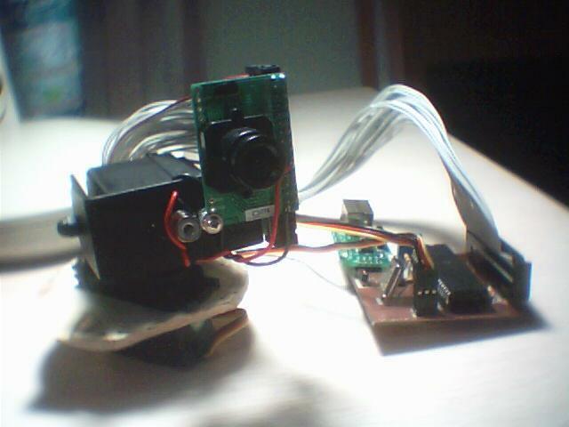
14 Figure 3 Figure 4
3.3V regulator. JA H-bridge. Doc: page 1 of 7
 Cerebot Reference Manual Revision: February 9, 2009 Note: This document applies to REV B-E of the board. www.digilentinc.com 215 E Main Suite D Pullman, WA 99163 (509) 334 6306 Voice and Fax Overview The
Lab 3: Embedded Systems
 THE PENNSYLVANIA STATE UNIVERSITY EE 3OOW SECTION 3 FALL 2015 THE DREAM TEAM Lab 3: Embedded Systems William Stranburg, Sean Solley, Sairam Kripasagar Table of Contents Introduction... 3 Rationale... 3
Final Report. Project Title: E-Scope Team Name: Awesome
 EEL 4924 Electrical Engineering Design (Senior Design) Final Report 04 August 2009 Team Members: Charlie Lamantia Scott Lee Project Abstract: Project Title: E-Scope Team Name: Awesome In match shooting
GP4 PC Servo Control Kit 2003 by AWC
 GP4 PC Servo Control Kit 2003 by AWC AWC 310 Ivy Glen League City, TX 77573 (281) 334-4341 http://www.al-williams.com/awce.htm V1.0 30 Aug 2003 Table of Contents Overview...1 If You Need Help...1 Building...1
Project Final Report: Directional Remote Control
 Project Final Report: by Luca Zappaterra xxxx@gwu.edu CS 297 Embedded Systems The George Washington University April 25, 2010 Project Abstract In the project, a prototype of TV remote control which reacts
Digital-to-Analog Converter. Lab 3 Final Report
 Digital-to-Analog Converter Lab 3 Final Report The Ion Cannons: Shrinand Aggarwal Cameron Francis Nicholas Polito Section 2 May 1, 2017 1 Table of Contents Introduction..3 Rationale..3 Theory of Operation.3
ArduCAM USB Camera Shield
 ArduCAM USB Camera Shield Application Note for MT9V034 Rev 1.0, June 2017 Table of Contents 1 Introduction... 2 2 Hardware Installation... 2 3 Run the Demo... 3 4 Tune the Sensor Registers... 4 4.1 Identify
EVDP610 IXDP610 Digital PWM Controller IC Evaluation Board
 IXDP610 Digital PWM Controller IC Evaluation Board General Description The IXDP610 Digital Pulse Width Modulator (DPWM) is a programmable CMOS LSI device, which accepts digital pulse width data from a
EE 318 Electronic Design Lab 1 project report. Surveillance Robot
 EE 318 Electronic Design Lab 1 project report Surveillance Robot Group D3 Shreyans Gandhi (06d07005) Mohit Dandekar (06d07006) Praveen Tamhankar (06d07007) Guide : Prof. Vivek Agarwal Department of Electrical
FABO ACADEMY X ELECTRONIC DESIGN
 ELECTRONIC DESIGN MAKE A DEVICE WITH INPUT & OUTPUT The Shanghaino can be programmed to use many input and output devices (a motor, a light sensor, etc) uploading an instruction code (a program) to it
DASL 120 Introduction to Microcontrollers
 DASL 120 Introduction to Microcontrollers Lecture 2 Introduction to 8-bit Microcontrollers Introduction to 8-bit Microcontrollers Introduction to 8-bit Microcontrollers Introduction to Atmel Atmega328
Study of M.A.R.S. (Multifunctional Aero-drone for Remote Surveillance)
") Study of M.A.R.S. (Multifunctional Aero-drone for Remote Surveillance) Supriya Bhuran 1, Rohit V. Agrawal 2, Kiran D. Bombe 2, Somiran T. Karmakar 2, Ninad V. Bapat 2 1 Assistant Professor, Dept. Instrumentation,
Study of M.A.R.S. (Multifunctional Aero-drone for Remote Surveillance) Supriya Bhuran 1, Rohit V. Agrawal 2, Kiran D. Bombe 2, Somiran T. Karmakar 2, Ninad V. Bapat 2 1 Assistant Professor, Dept. Instrumentation,
ULS24 Frequently Asked Questions
 List of Questions 1 1. What type of lens and filters are recommended for ULS24, where can we source these components?... 3 2. Are filters needed for fluorescence and chemiluminescence imaging, what types
ADVANCED EMBEDDED MONITORING SYSTEM FOR ELECTROMAGNETIC RADIATION
 98 Chapter-5 ADVANCED EMBEDDED MONITORING SYSTEM FOR ELECTROMAGNETIC RADIATION 99 CHAPTER-5 Chapter 5: ADVANCED EMBEDDED MONITORING SYSTEM FOR ELECTROMAGNETIC RADIATION S.No Name of the Sub-Title Page
LDOR: Laser Directed Object Retrieving Robot. Final Report
 University of Florida Department of Electrical and Computer Engineering EEL 5666 Intelligent Machines Design Laboratory LDOR: Laser Directed Object Retrieving Robot Final Report 4/22/08 Mike Arms TA: Mike
muse Capstone Course: Wireless Sensor Networks
 muse Capstone Course: Wireless Sensor Networks Experiment for WCC: Channel and Antenna Characterization Objectives 1. Get familiar with the TI CC2500 single-chip transceiver. 2. Learn how the MSP430 MCU
Programming and Interfacing
 AtmelAVR Microcontroller Primer: Programming and Interfacing Second Edition f^r**t>*-**n*c contents Preface xv AtmelAVRArchitecture Overview 1 1.1 ATmegal64 Architecture Overview 1 1.1.1 Reduced Instruction
CEEN Bot Lab Design A SENIOR THESIS PROPOSAL
 CEEN Bot Lab Design by Deborah Duran (EENG) Kenneth Townsend (EENG) A SENIOR THESIS PROPOSAL Presented to the Faculty of The Computer and Electronics Engineering Department In Partial Fulfillment of Requirements
EEL4914 Senior Design. Final Design Report
 EEL4914 Senior Design Final Design Report Electric Super Bike The Best Team in the World Matt Fisher madfish@ufl.edu Richard Orr gautama@ufl.edu 21 April 2008 1 Contents Contents...2 Abstract...3 Project
Arduino STEAM Academy Arduino STEM Academy Art without Engineering is dreaming. Engineering without Art is calculating. - Steven K.
 Arduino STEAM Academy Arduino STEM Academy Art without Engineering is dreaming. Engineering without Art is calculating. - Steven K. Roberts Page 1 See Appendix A, for Licensing Attribution information
Knight Light. LED Chess. Nick DeSantis Alex Haas Bryan Salicco. Senior Design Group 16 Spring 2013
 Knight Light LED Chess Nick DeSantis Alex Haas Bryan Salicco Senior Design Group 16 Spring 2013 Motivation Chess is a tricky game to learn. Video games have taken over and kids don't learn about classic
1 Introduction. 2 Embedded Electronics Primer. 2.1 The Arduino
 Beginning Embedded Electronics for Botballers Using the Arduino Matthew Thompson Allen D. Nease High School matthewbot@gmail.com 1 Introduction Robotics is a unique and multidisciplinary field, where successful
International Journal of Advances in Science and Technology (IJAST)
") Signal detection and FFT calculation using ATmega644 microcontroller D. Sarkar 1, A.Chowdhury 2 1,2 Department of Electronics & Communication Engineering, NIT Agartala, India ABSTRACT: Detection of a signal
Signal detection and FFT calculation using ATmega644 microcontroller D. Sarkar 1, A.Chowdhury 2 1,2 Department of Electronics & Communication Engineering, NIT Agartala, India ABSTRACT: Detection of a signal
EEL5666C IMDL Spring 2006 Student: Andrew Joseph. *Alarm-o-bot*
 EEL5666C IMDL Spring 2006 Student: Andrew Joseph *Alarm-o-bot* TAs: Adam Barnett, Sara Keen Instructor: A.A. Arroyo Final Report April 25, 2006 Table of Contents Abstract 3 Executive Summary 3 Introduction
CMPE490/450 FINAL REPORT DYNAMIC CAMERA STABILIZATION SYSTEM GROUP 7. DAVID SLOAN REEGAN WOROBEC
 CMPE490/450 FINAL REPORT DYNAMIC CAMERA STABILIZATION SYSTEM GROUP 7 DAVID SLOAN dlsloan@ualberta.ca REEGAN WOROBEC rworobec@ualberta.ca DECLARATION OF ORIGINAL CONTENT The design elements of this project
Project Name: SpyBot
 EEL 4924 Electrical Engineering Design (Senior Design) Final Report April 23, 2013 Project Name: SpyBot Team Members: Name: Josh Kurland Name: Parker Karaus Email: joshkrlnd@gmail.com Email: pbkaraus@ufl.edu
Training Schedule. Robotic System Design using Arduino Platform
 Training Schedule Robotic System Design using Arduino Platform Session - 1 Embedded System Design Basics : Scope : To introduce Embedded Systems hardware design fundamentals to students. Processor Selection
Using Z8 Encore! XP MCU for RMS Calculation
 Application te Using Z8 Encore! XP MCU for RMS Calculation Abstract This application note discusses an algorithm for computing the Root Mean Square (RMS) value of a sinusoidal AC input signal using the
International Journal of Advance Engineering and Research Development
 Scientific Journal of Impact Factor (SJIF): 4.14 International Journal of Advance Engineering and Research Development Volume 3, Issue 2, February -2016 e-issn (O): 2348-4470 p-issn (P): 2348-6406 SIMULATION
Navigation and Thrust System for AUVSI RoboBoat
 Navigation and Thrust System for AUVSI RoboBoat Author: Evan J. Dinelli Team Members: Michael S. Barnes and Dan R. Van de Water Advisor: Dr. Gary Dempsey Client: Mr. Nick Schmidt Department of Electrical
SMARTALPHA RF TRANSCEIVER
 SMARTALPHA RF TRANSCEIVER Intelligent RF Modem Module RF Data Rates to 19200bps Up to 300 metres Range Programmable to 433, 868, or 915MHz Selectable Narrowband RF Channels Crystal Controlled RF Design
CMOS OV7725 Camera Module 1/4-Inch 0.3-Megapixel Module Datasheet
 CMOS OV7725 Camera Module 1/4-Inch 0.3-Megapixel Module Datasheet Rev 2.0, June 2015 Table of Contents 1 Introduction... 2 2 Features... 3 3 Key Specifications... 3 4 Application... 3 5 Pin Definition...
CMOS MT9D112 Camera Module 1/4-Inch 3-Megapixel Module Datasheet
 CMOS MT9D112 Camera Module 1/4-Inch 3-Megapixel Module Datasheet Rev 1.0, Mar 2013 3M Pixels CMOS MT9D112 CAMERA MODULE Table of Contents 1 Introduction... 2 2 Features... 3 3 Key Specifications... 3 4
uc Crash Course Whats is covered in this lecture Joshua Childs Joshua Hartman A. A. Arroyo 9/7/10
 uc Crash Course Joshua Childs Joshua Hartman A. A. Arroyo Whats is covered in this lecture ESD Choosing A Processor GPIO USARTS o RS232 o SPI Timers o Prescalers o OCR o ICR o PWM ADC Interupts 1 ESD KILLS!
ECE 511: FINAL PROJECT REPORT GROUP 7 MSP430 TANK
 ECE 511: FINAL PROJECT REPORT GROUP 7 MSP430 TANK Team Members: Andrew Blanford Matthew Drummond Krishnaveni Das Dheeraj Reddy 1 Abstract: The goal of the project was to build an interactive and mobile
CMOS MT9D111Camera Module 1/3.2-Inch 2-Megapixel Module Datasheet
 CMOS MT9D111Camera Module 1/3.2-Inch 2-Megapixel Module Datasheet Rev 1.0, Mar 2013 Table of Contents 1 Introduction... 2 2 Features... 2 3 Block Diagram... 3 4 Application... 4 5 Pin Definition... 6 6
Programming 2 Servos. Learn to connect and write code to control two servos.
 Programming 2 Servos Learn to connect and write code to control two servos. Many students who visit the lab and learn how to use a Servo want to use 2 Servos in their project rather than just 1. This lesson
MAKEVMA502 BASIC DIY KIT WITH ATMEGA2560 FOR ARDUINO USER MANUAL
 BASIC DIY KIT WITH ATMEGA2560 FOR ARDUINO USER MANUAL USER MANUAL 1. Introduction To all residents of the European Union Important environmental information about this product This symbol on the device
Ultrasonic Positioning System EDA385 Embedded Systems Design Advanced Course
 Ultrasonic Positioning System EDA385 Embedded Systems Design Advanced Course Joakim Arnsby, et04ja@student.lth.se Joakim Baltsén, et05jb4@student.lth.se Simon Nilsson, et05sn9@student.lth.se Erik Osvaldsson,
FINAL DESIGN REPORT. Dodge This! DODGERS: Cristobal Rivero Derek Fairbanks 4/21/2009
 FINAL DESIGN REPORT Dodge This! DODGERS: Cristobal Rivero Derek Fairbanks 4/21/2009 Abstract: Our project is to develop an automatic dodge ball game. It consists of an infrared video camera, computer,
Monitoring the Transformer Oil Temperature and Load Sharing Using Gsm
 Monitoring the Transformer Oil Temperature and Load Sharing Using Gsm Ramadas.K 1, Madasamy.P 2 1, 2 Assistant Professor, Department of Electrical and Electronics Engineering, Aliquippa Chettiar College
Embedded & Robotics Training
 Embedded & Robotics Training WebTek Labs creates and delivers high-impact solutions, enabling our clients to achieve their business goals and enhance their competitiveness. With over 13+ years of experience,
CHAPTER 2 LITERATURE REVIEW
 CHAPTER 2 LITERATURE REVIEW 2.1 Reviews from Other Projects There are numerous projects that are associated with this project. To make things easier, this section will focus on few projects that are heavily
RC Filters and Basic Timer Functionality
 RC-1 Learning Objectives: RC Filters and Basic Timer Functionality The student who successfully completes this lab will be able to: Build circuits using passive components (resistors and capacitors) from
PRELIMINARY DESIGN REPORT
 PRELIMINARY DESIGN REPORT Dodge This! DODGERS: Cristobal Rivero Derek Fairbanks 1/27/2009 Abstract: Our project is to develop an automatic dodge ball game. It consists of an infrared video camera, computer,
Boozer Cruiser. EEL Electrical Engineering Design 2 Final Design Report. April 23, The Mobile Bartending Robot.
 EEL4924 - Electrical Engineering Design 2 Final Design Report April 23, 2013 Boozer Cruiser The Mobile Bartending Robot Team Members: Mackenzie Banker Perry Fowlkes mbanker@ufl.edu perry.pfowlkes@gmail.com
Wireless Controlled Residential Air Vent: A Smartphone Interface for Air Direction
 UNIVERSITY OF NEVADA LAS VEGAS DEPARTMENT OF ELECTRICAL AND COMPUTER ENGINEERING EE & CPE 497 Senior Design Fall 2014 Wireless Controlled Residential Air Vent: A Smartphone Interface for Air Direction
AN ARDUINO CONTROLLED CHAOTIC PENDULUM FOR A REMOTE PHYSICS LABORATORY
 AN ARDUINO CONTROLLED CHAOTIC PENDULUM FOR A REMOTE PHYSICS LABORATORY J. C. Álvarez, J. Lamas, A. J. López, A. Ramil Universidade da Coruña (SPAIN) carlos.alvarez@udc.es, jlamas@udc.es, ana.xesus.lopez@udc.es,
AUTOMATIC ELECTRICITY METER READING AND REPORTING SYSTEM
 AUTOMATIC ELECTRICITY METER READING AND REPORTING SYSTEM Faris Shahin, Lina Dajani, Belal Sababha King Abdullah II Faculty of Engineeing, Princess Sumaya University for Technology, Amman 11941, Jordan
ZKit-51-RD2, 8051 Development Kit
 ZKit-51-RD2, 8051 Development Kit User Manual 1.1, June 2011 This work is licensed under the Creative Commons Attribution-Share Alike 2.5 India License. To view a copy of this license, visit http://creativecommons.org/licenses/by-sa/2.5/in/
EECE494: Computer Bus and SoC Interfacing. Serial Communication: RS-232. Dr. Charles Kim Electrical and Computer Engineering Howard University
 EECE494: Computer Bus and SoC Interfacing Serial Communication: RS-232 Dr. Charles Kim Electrical and Computer Engineering Howard University Spring 2014 1 Many types of wires/pins in the communication
Arduino Uno Pinout Book
 Arduino Uno Pinout Book 1 / 6 2 / 6 3 / 6 Arduino Uno Pinout Book Arduino Uno pinout - Power Supply. There are 3 ways to power the Arduino Uno: Barrel Jack - The Barrel jack, or DC Power Jack can be used
1. GENERAL DESCRIPTION FEATURES PIN DESCRIPTION BLOCK DIAGRAM... 5
 Table of Contents- 1. GENERAL DESCRIPTION... 2 2. FEATURES... 3 3. PIN DESCRIPTION... 4 4. BLOCK DIAGRAM... 5 5. ELECTRICAL CHARACTERISTICS... 5 5.1 Absolute Maximum Ratings... 5 5.2 D.C. Characteristics...
SonoLab Echo-I User Manual
 SonoLab Echo-I User Manual Overview: SonoLab Echo-I is a single board digital ultrasound pulse-echo solution. The system has a built in 50 volt high voltage generation circuit, a bipolar pulser, a transmit/receive
Gregory Bock, Brittany Dhall, Ryan Hendrickson, & Jared Lamkin Project Advisors: Dr. Jing Wang & Dr. In Soo Ahn Department of Electrical and Computer
 Gregory Bock, Brittany Dhall, Ryan Hendrickson, & Jared Lamkin Project Advisors: Dr. Jing Wang & Dr. In Soo Ahn Department of Electrical and Computer Engineering March 1 st, 2016 Outline 2 I. Introduction
Terasic TRDB_D5M Digital Camera Package TRDB_D5M. 5 Mega Pixel Digital Camera Development Kit
 Terasic TRDB_D5M Digital Camera Package TRDB_D5M 5 Mega Pixel Digital Camera Development Kit Document Version 1.2 AUG. 10, 2010 by Terasic Terasic TRDB_D5M Page Index CHAPTER 1 ABOUT THE KIT... 1 1.1 KIT
Design and Implementation of an Unmanned Ground Vehicle
 Design and Implementation of an Unmanned Ground Vehicle Abstract Shreyas H, Thirumalesh H S Department of Electrical and Electronics Engineering, SJCE, Mysore, India Email: shreyas9693@gmail.com, hsthirumalesh@gmail.com
Preliminary Design Report. Project Title: Mutli-Function Pontoon (MFP)
") EEL 4924 Electrical Engineering Design (Senior Design) Preliminary Design Report 31 January 2011 Project Title: Mutli-Function Pontoon (MFP) Team Members: Name: Mikkel Gabbadon Name: Sheng-Po Fang Project
EEL 4924 Electrical Engineering Design (Senior Design) Preliminary Design Report 31 January 2011 Project Title: Mutli-Function Pontoon (MFP) Team Members: Name: Mikkel Gabbadon Name: Sheng-Po Fang Project
Homework 9: Software Design Considerations
 Homework 9: Software Design Considerations Team Code Name: Treasure Chess Group No. 2 Team Member Completing This Homework: Parul Schroff E-mail Address of Team Member: pschroff @ purdue.edu Evaluation:
SAE Formula Car Data Acquisition & Display System. Joseph Groe, Michelle Ohlson, & Miles Homler Advisor: Professor Gutschlag
 SAE Formula Car Data Acquisition & Display System Joseph Groe, Michelle Ohlson, & Miles Homler Advisor: Professor Gutschlag Agenda Problem Background Problem Statement System Diagram Project Functional
Stensat Transmitter Module
 Stensat Transmitter Module Stensat Group LLC Introduction The Stensat Transmitter Module is an RF subsystem designed for applications where a low-cost low-power radio link is required. The Transmitter
Imaging serial interface ROM
 Page 1 of 6 ( 3 of 32 ) United States Patent Application 20070024904 Kind Code A1 Baer; Richard L. ; et al. February 1, 2007 Imaging serial interface ROM Abstract Imaging serial interface ROM (ISIROM).
Written by Hans Summers Monday, 22 September :14 - Last Updated Friday, 16 January :43
 This modification turns the Ultimate3 kit into an accurate GPS-disciplined frequency reference (approx 0.03Hz accuracy). The firmware has NOT yet been updated to operate with the Si5351A synthesiser module
A Solar-Powered Wireless Data Acquisition Network
 A Solar-Powered Wireless Data Acquisition Network E90: Senior Design Project Proposal Authors: Brian Park Simeon Realov Advisor: Prof. Erik Cheever Abstract We are proposing to design and implement a solar-powered
EE 314 Spring 2003 Microprocessor Systems
 EE 314 Spring 2003 Microprocessor Systems Laboratory Project #9 Closed Loop Control Overview and Introduction This project will bring together several pieces of software and draw on knowledge gained in
Multi Frequency RFID Read Writer System
 Multi Frequency RFID Read Writer System Uppala Sunitha 1, B Rama Murthy 2, P Thimmaiah 3, K Tanveer Alam 1 PhD Scholar, Department of Electronics, Sri Krishnadevaraya University, Anantapur, A.P, India
Doc: page 1 of 6
 VmodCAM Reference Manual Revision: July 19, 2011 Note: This document applies to REV C of the board. 1300 NE Henley Court, Suite 3 Pullman, WA 99163 (509) 334 6306 Voice (509) 334 6300 Fax Overview The
Index Terms IR communication; MSP430; TFDU4101; Pre setter
 Design and Development of Contactless Communication Module for Pre setter of Underwater Vehicles J.Lavanyambhika, **D.Madhavi *Digital Systems and Signal Processing in Electronics and Communication Engineering,
Robotic Development Kit. Powered using ATMEL technology
 Robotic Development Kit Powered using ATMEL technology Index 1. System overview 2. Technology overview 3. Individual dev-kit components I. Robot II. Remote III. IR-Pod IV. Base-Station V. RFID 4. Robonii
SC16A SERVO CONTROLLER
 SC16A SERVO CONTROLLER User s Manual V2.0 September 2008 Information contained in this publication regarding device applications and the like is intended through suggestion only and may be superseded by
Aerial Photographic System Using an Unmanned Aerial Vehicle
 Aerial Photographic System Using an Unmanned Aerial Vehicle Second Prize Aerial Photographic System Using an Unmanned Aerial Vehicle Institution: Participants: Instructor: Chungbuk National University
Embedded Test System. Design and Implementation of Digital to Analog Converter. TEAM BIG HERO 3 John Sopczynski Karim Shik-Khahil Yanzhe Zhao
 Embedded Test System Design and Implementation of Digital to Analog Converter TEAM BIG HERO 3 John Sopczynski Karim Shik-Khahil Yanzhe Zhao EE 300W Section 1 Spring 2015 Big Hero 3 DAC 2 INTRODUCTION (KS)
Applications. Operating Modes. Description. Part Number Description Package. Many to one. One to one Broadcast One to many
 RXQ2 - XXX GFSK MULTICHANNEL RADIO TRANSCEIVER Intelligent modem Transceiver Data Rates to 100 kbps Selectable Narrowband Channels Crystal controlled design Supply Voltage 3.3V Serial Data Interface with
Low Power with Long Range RF Module DATASHEET Description
 Wireless-Tag WT-900M Low Power with Long Range RF Module DATASHEET Description WT-900M is a highly integrated low-power half-'duplex RF transceiver module embedding high-speed low-power MCU and high-performance
Open Source Digital Camera on Field Programmable Gate Arrays
 Open Source Digital Camera on Field Programmable Gate Arrays Cristinel Ababei, Shaun Duerr, Joe Ebel, Russell Marineau, Milad Ghorbani Moghaddam, and Tanzania Sewell Department of Electrical and Computer
Wireless Music Dock - WMD Portable Music System with Audio Effect Applications
 Wireless Music Dock - WMD Portable Music System with Audio Effect Applications Preliminary Design Report EEL 4924 Electrical Engineering Design (Senior Design) 26 January 2011 Members: Jeffrey Post and
Servo Sequencer Servo Robot motion controller & General Purpose microcontroller board
 Robot Construction Component Servo Sequencer Servo Robot motion controller & General Purpose microcontroller board The servo sequencer is in reality a general purpose reprogrammable microcontroller board
Design and Implementation of AT Mega 328 microcontroller based firing control for a tri-phase thyristor control rectifier
 Design and Implementation of AT Mega 328 microcontroller based firing control for a tri-phase thyristor control rectifier 1 Mr. Gangul M.R PG Student WIT, Solapur 2 Mr. G.P Jain Assistant Professor WIT,
Interfacing Sensors & Modules to Microcontrollers
 Interfacing Sensors & Modules to Microcontrollers Presentation Topics I. Microprocessors & Microcontroller II. III. Hardware/software Tools for Interfacing Type of Sensors/Modules IV. Level Inputs (Digital
Datasheet DS0011 AM093 Wireless Meter-Bus Dual Band 169/868MHz Narrowband Modem Advance Information Production Status Production
 Datasheet DS0011 AM093 Wireless Meter-Bus Dual Band 169/868MHz Narrowband Modem Production Status Production Important Information The information contained in this document is subject to change without
Navigation and Thrust System for AUVSI RoboBoat
 Navigation and Thrust System for AUVSI RoboBoat Authors: Michael S. Barnes, Evan J. Dinelli, Dan R. Van de Water Advisor: Dr. Gary Dempsey Client: Mr. Nick Schmidt Department of Electrical and Computer
Advanced RTK GPS / Compass module with 100x100 mm ground plane and 32-bit MCU
 TGM100 Advanced RTK GPS / Compass module with 100x100 mm ground plane and 32-bit MCU Data Sheet Revision: 0.3 Date of Last Revision: 18 April 2017 True Flight Technology, Inc. ( TFT ) reserves the right
Lesson UART. Clock Systems and Timing UART (Universal Asynchronous Receiver-Transmitter) Queues Lab Assignment: UART
 Queues Lab Assignment: UART") Lesson UART Clock Systems and Timing UART (Universal Asynchronous Receiver-Transmitter) Queues Lab Assignment: UART Clock Systems and Timing Clock System & Timing A crystal oscillator is typically used
Lesson UART Clock Systems and Timing UART (Universal Asynchronous Receiver-Transmitter) Queues Lab Assignment: UART Clock Systems and Timing Clock System & Timing A crystal oscillator is typically used
DESCRIPTION DOCUMENT FOR WiFi <-> RS485 <-> LoRa DEVICE BOARD HARDWARE REVISION 0.1
 DESCRIPTION DOCUMENT FOR WiFi RS485 LoRa DEVICE BOARD HARDWARE REVISION 0.1 Department Name Signature Date Author Reviewer Approver Revision History Rev Description of Change A Initial Release
SNIOT702 Specification. Version number:v 1.0.1
 Version number:v 1.0.1 Catelog 1 Product introduction... 1 1.1 Product introduction... 1 1.2 Product application... 1 1.3 Main characteristics... 2 1.4 Product advantage... 3 2 Technical specifications...
UNIVERSITY OF VICTORIA FACULTY OF ENGINEERING. SENG 466 Software for Embedded and Mechatronic Systems. Project 1 Report. May 25, 2006.
 UNIVERSITY OF VICTORIA FACULTY OF ENGINEERING SENG 466 Software for Embedded and Mechatronic Systems Project 1 Report May 25, 2006 Group 3 Carl Spani Abe Friesen Lianne Cheng 03-24523 01-27747 01-28963
3D ULTRASONIC STICK FOR BLIND
 3D ULTRASONIC STICK FOR BLIND Osama Bader AL-Barrm Department of Electronics and Computer Engineering Caledonian College of Engineering, Muscat, Sultanate of Oman Email: Osama09232@cceoman.net Abstract.
A Model Based Approach for Human Recognition and Reception by Robot
 16 MHz ARDUINO A Model Based Approach for Human Recognition and Reception by Robot Prof. R. Sunitha Department Of ECE, N.R.I Institute Of Technology, J.N.T University, Kakinada, India. V. Sai Krishna,
Closed-Loop Transportation Simulation. Outlines
 Closed-Loop Transportation Simulation Deyang Zhao Mentor: Unnati Ojha PI: Dr. Mo-Yuen Chow Aug. 4, 2010 Outlines 1 Project Backgrounds 2 Objectives 3 Hardware & Software 4 5 Conclusions 1 Project Background
KUMU A O CUBESAT: THERMAL SENSORS ON A CUBESAT
 KUMU A O CUBESAT: THERMAL SENSORS ON A CUBESAT Tyson K. Seto-Mook Department of Electrical Engineering University of Hawai i at Mānoa Honolulu, HI 96822 INTRODUCTION A. Abstract CubeSat is a project that
Electronics Design Laboratory Lecture #9. ECEN 2270 Electronics Design Laboratory
 Electronics Design Laboratory Lecture #9 Electronics Design Laboratory 1 Notes Finishing Lab 4 this week Demo requires position control using interrupts and two actions Rotate a given angle Move forward
AUTOMATIC INSPECTION SYSTEM FOR CMOS CAMERA DEFECT. Byoung-Wook Choi*, Kuk Won Ko**, Kyoung-Chul Koh***, Bok Shin Ahn****
 AUTOMATIC INSPECTION SYSTEM FOR CMOS CAMERA DEFECT Byoung-Wook Choi*, Kuk Won Ko**, Kyoung-Chul Koh***, Bok Shin Ahn**** * Dept. of Electrical Engineering, Seoul Nat'l Univ. of Technology, Seoul, Korea
Walking Robot with Vision. Group 14 Anselet Jacques Phillipe Jean-Jumeau Steven Schultz
 Walking Robot with Vision Group 14 Anselet Jacques Phillipe Jean-Jumeau Steven Schultz Our Mission, Our Purpose We intend to build a six-legged robot that will be able to walk, be controlled wirelessly
HAND GESTURE CONTROLLED ROBOT USING ARDUINO
 HAND GESTURE CONTROLLED ROBOT USING ARDUINO Vrushab Sakpal 1, Omkar Patil 2, Sagar Bhagat 3, Badar Shaikh 4, Prof.Poonam Patil 5 1,2,3,4,5 Department of Instrumentation Bharati Vidyapeeth C.O.E,Kharghar,Navi
BOAT LOCALIZATION AND WARNING SYSTEM FOR BORDER IDENTIFICATION
 BOAT LOCALIZATION AND WARNING SYSTEM FOR BORDER IDENTIFICATION Mr.Vasudevan, Ms.Aarthi.C, Ms.Arunthathi.M, Ms.Durgakalaimathi.L.T, Ms.Evangelin Darvia.P 1Professor, Dept. of ECE, Panimalar Engineering
Mapping device with wireless communication
 University of Arkansas, Fayetteville ScholarWorks@UARK Electrical Engineering Undergraduate Honors Theses Electrical Engineering 12-2011 Mapping device with wireless communication Xiangyu Liu University
Introduction to the Arduino Kit
 1 Introduction to the Arduino Kit Introduction Arduino is an open source microcontroller platform used for sensing both digital and analog input signals and for sending digital and analog output signals
ArduCAM USB Camera Shield
 ArduCAM USB Camera Shield Application Note for MT9J001 Rev 1.0, Aug 2017 Table of Contents 1 Introduction... 2 2 Hardware Installation... 2 3 Run the Demo... 3 4 Tune the Sensor Registers... 4 4.1 Identify
ARDUINO / GENUINO. start as professional. short course in a book. faculty of engineering technology
 ARDUINO / GENUINO start as professional short course in a book faculty of engineering technology Publisher Universiti Malaysia Pahang Kuantan 2017 Copyright Universiti Malaysia Pahang, 2017 First Published,
RPLIDAR A1. Introduction and Datasheet. Low Cost 360 Degree Laser Range Scanner rev.2.1. Model: A1M8. Shanghai Slamtec.Co.
 www.slamtec.com 2018-02-05 rev.2.1 RPLIDAR A1 Low Cost 360 Degree Laser Range Scanner Introduction and Datasheet Model: A1M8 Shanghai Slamtec.Co.,Ltd Contents CONTENTS... 1 INTRODUCTION... 3 SYSTEM CONNECTION...