Mixed Reality Simulators
|
|
|
- Marian Hodges
- 6 years ago
- Views:
Transcription

1 UNIVERSITY OF THE WITWATERSRAND MASTER S DISSERTATION Mixed Reality Simulators Author: Natalie AUSMEIER Supervisor: Prof. Turgay CELIK A Dissertation submitted to the Faculty of Science, University of the Witwatersrand, Johannesburg, in fulfilment of the requirements for the degree of Master of Science Pretoria, May 2017
2 Declaration of Authorship I, Natalie AUSMEIER, declare that this Dissertation is my own, unaided work. It is being submitted for the Degree of Master of Science at the University of the Witwatersrand, Johannesburg. It has not been submitted before for any degree or examination at any other University. (Signature of candidate) day of 20 in i
3 It is often said that before you die your life passes before your eyes. It is in fact true. It s called living. Terry Pratchett
4 Abstract Virtual Reality (VR) is widely used in training simulators of dangerous or expensive vehicles such as aircraft or heavy mining machinery. The vehicles often have very complicated controls that users need to master before attempting to operate a real world version of the machine. VR allows users to safely train in a simulated environment without the risk of injury or damaging expensive equipment in the field. VR however visually cuts off the user from the real environment, which may obtain obstructions. Users are unable to safely move or gesture while wearing a VR headset. Additionally users are unable to use standard input devices such as mice and keyboards. By mixing in a live view of the the real world, the user can still see and interact with the physical environment. The contribution of this research is presenting ways of using Mixed Reality to enhance the user experience of traditional VR based simulators. Mixed Reality improves on traditional VR simulators by allowing the user the safety and freedom of not being cut off from the real world, allowing interaction and the tactile feedback of interacting with complex physical controls, while still allowing simultaneous use of virtual controls and by adding a real world reference point to aid in diminishing simulator sickness caused by visual motion.
5 Acknowledgements I would like to acknowledge the inputs and encouragement from Turgay Celik, Jaco Cronje, Jason De Villiers, Bernardt Duvenhage, Asheer Bachoo and David Baxter. iv
6 Contents Declaration of Authorship i Abstract iii Acknowledgements iv Contents List of Figures List of Tables Contents Abbreviations v vii ix x xi 1 Introduction Background Hardware Console Based Simulators Virtual Console Based Simulators Motivation Aim of the Research Hypotheses Immersion Usability Comfort Limitations of the Research Outline of the Dissertation Related Work Mixed Reality Virtual Input Devices Simulator Sickness Physical Motion Simulator Sickness Visual Motion Simulator Sickness v
7 Contents vi 3 Methodology Method 1: Virtual Screens Hardware Implementation Camera and Leap Mounting Software Implementation Camera Calibration and Alignment Lens Distortion Compensation Perspective Transform Between Cameras Camera Alignment and Blending Virtual Camera Placement Augmented Reality Targets Virtual Screen and Instrument Placement Method 2: Stencil Cutouts Stencils Instead of Virtual Screens A More Portable Solution Implementing Stencil Cutouts Evaluation and Usability Test prototypes Objectively Evaluating the User Input QTE Setup Data Collection QTE Results Subjective Usability Questionnaire Questionnaire Setup Data Collection Questionnaire Results Findings Regarding Immersion Findings Regarding Usability Findings Regarding Comfort and Simulator Sickness Conclusion Summary of Contribution Summary of Methodology Conclusion of Usability Test Findings Recommendations and Future Work A Publications 60 B Usability Questionnaire Results 66 C Quick Time Event Results 78 Bibliography 86
8 List of Figures 1.1 Virtual Reality Concept Hardware Console Based Simulator Virtual Console Based Simulator Virtual Reality Headset Augmented Reality Headset A Multi-Monitor Setup vs. a VR Headset A VR Headset and an Optical-See-Through Device A Video See-Through Headset Mounting Options for Stereo Camera Pair Stereo Camera Parallax Stereo Camera Feed with Virtual Objects Colour Segmentation with Background Interference Edge Detection for Combination with Colour Segmentation Depth Image from Stereo Finding Fingertips with Kinect Depth Sensor Leap Motion Hand and Finger Tracker Virtual Screen Concept Hardware Components for the Oculus Rift Prototype Camera and Leap Mounting Field of View of the Cameras Software Pipeline Radial Distortion Tangential Distortion Lens Distortion Compensation Perspective Transform using the Homography Matrix Perspective Transform Between Cameras Camera Alignment and Blending Inter Camera and Inter Pupillary Distance Example AR Image Targets Virtual Camera Alignment Virtual Screens Relative to Camera Virtual Screen Configurations Examples The Concept of Virtual Screens vs. Stencil Cutouts Hardware Components for the Mobile Prototype Stencil Cutout Example Tracked Controller Stencil Cutout vii
9 List of Figures viii 4.1 Coloured Buttons for Quick Time Events Quick Time Sequence Quick Time Sequence Results Flight Simulator with Video Background Subjective Usability Questionnaire Average Usability Questionnaire Scores Subjective Usability Questionnaire Scale Comparison of the Two Hardware Approaches
10 List of Tables 1.1 Pros and Cons of a Hardware Console Based Simulator Pros and Cons of a Virtual Console Based Simulator Specifications for Hardware Components Specifications for Mobile Hardware Components Usability Study Participant List ix
11 Listings 3.1 Lens Distortion Compensation Perspective Transform Calculation Shader that Sets Stencil Buffer to Shader that Renders when the Stencil Buffer Equals Saved QTE Results x
12 Abbreviations 2D 3D AR CMOS FOV GPU ICD IPD IR LD LED MR NASA OST PSO QTE VR (2)Two Dimensional (3)Three Dimensional Augmented Reality Complementary Metal Oxide Semiconductor Field Of View Graphics Processing Unit Inter Camera Distance Inter Pupillary Distance Infra Red Labyrinthine Defectives Light Emitting Diode Mixed Reality National Aeronautics and Space Administration Optical See Through Particle Swarm Optimisation Quick Time Event Virtual Reality xi

13 Chapter 1 Introduction 1.1 Background Virtual Reality (VR) places a user in a computer simulated environment, aimed to mimic real world scenarios. VR is widely used in training simulators of dangerous or expensive vehicles such as aircraft or heavy mining machinery. The vehicles often have very complicated instruments and controls that users need to master before attempting to operate a real world version of the machine. VR allows users to safely train in a simulated environment without the risk of damaging expensive equipment in the field. Figure 1.1 demonstrates the concept of entering a virtual world by means of computer simulation, the user is using a computer running simulation software to drive a virtual car. FIGURE 1.1: The Concept of Virtual Reality. 1

14 Chapter 1. Introduction 2 There are two ways in which traditional simulators approach VR, Hardware Console Based Simulators and Virtual Console Based Simulators Hardware Console Based Simulators A scale replica of the vehicle console is built containing the exact instruments and controls as its real world counter part. These simulators often operate on a base capable of simulating the motion of the vehicle as well. FIGURE 1.2: Example of a Hardware Console Based Simulator from Thales [1]. Figure 1.2 shows an example of a Thales [1] aircraft simulator with physical cockpits representing the exact model of each aircraft. The hardware console perfectly matches and functions like that of the real aircraft or vehicle and the motion bases matches the movement of the real vehicle. Projectors or multiple monitors usually provide the user with an out the window view of a virtual world. The hardware console, motion base and surround view makes for a very realistic simulator experience.
15 Chapter 1. Introduction 3 This approach is however very costly and requires a fixed setup in a simulator room or transportable container. If the simulator is completely software based, it can easily be setup anywhere for mobile training solutions and at a lower cost. Hardware console based simulators are also very specific to the model of the vehicle it was designed for; the entire console needs to be replaced for a different model of vehicle being trained. In a virtual or software based simulator, the same virtual world could be used with various vehicle models. As discussed in section 2, a hardware console based simulator is more likely to cause simulator sickness than simulators with no motion base. This is partly due to discrepancies between the physical movement of the motion base and the visuals of the simulator. Table 1.1 summarises the pros and cons of a hardware console based simulator. Pros The real instruments and controls of the vehicle are used The physical controls give tactile feedback The vehicle can physically move and rotate on top of a motion base There is often a 360 surround view of the world Cons The system can be costly The system can t easily be moved and used at different locations Motion base movement does not always perfectly match the visuals. Motion bases are more likely to cause simulator sickness during use The instruments and controls are for a specific vehicle model, and can t easily be swapped out TABLE 1.1: Pros and Cons of a Hardware Console Based Simulator

16 Chapter 1. Introduction Virtual Console Based Simulators A virtual representation of the vehicle console is represented in the simulated environment. This approach is completely software based, the vehicle instruments, controls and out the window view are all virtual. The virtual controls and instruments are usually not interactive and the simulator is controlled using generic input devices. FIGURE 1.3: Example of a Virtual Console Based Simulator from MS Flight [2]. Figure 1.3 shows an example of Microsoft Flight [2], a commercially available flight simulator with virtual instruments and controls. This allows different models of aircraft to be easily swapped in. The virtual controls can be combined with physical controls such as flight yokes or steering wheels for a more realistic and tactile experience. Furthermore additional displays can be added for a larger field of view. As with hardware console based simulators, adding projectors or monitors makes the system more costly. Adding hardware also decreases the mobility of the system.

17 Chapter 1. Introduction 5 Virtual console based simulators do not provide any tactile feedback with the actual instruments and controls of the vehicle, making it a much less realistic simulator experience. Table 1.2 summarises the pros and cons of a virtual console based simulator. Pros Virtual consoles for different vehicle models can easily be swapped in Generic input devices can still provide tactile feedback A larger field of view can be added through additional display support The system relatively cheap The system is relatively easy to move and use at different locations Cons The virtual console can t be interacted with physically The system does not usually simulate physical movement via a motion base While more displays can be added, the system does not provide a 360 surround view of the world More displays means more cost and less mobility TABLE 1.2: Pros and Cons of a Virtual Console Based Simulator 1.2 Motivation To increase the immersion of virtual console based simulators, Virtual Reality (VR) headsets are often used, removing the need for costly and often bulky displays such as monitors and projectors. An example of an VR headset is shown in Figure 1.4. FIGURE 1.4: Example of a Virtual Reality Headset.
18 Chapter 1. Introduction 6 VR headsets used in current simulators, consist of a helmet with a small display in front of the wearer s eyes. The wearer s head is tracked and the display correctly reflects the direction the wearer is looking in. The participant is effectively taken out of the real world and placed within the simulated environment with a complete 360 view of the world. Data gloves are often used to track wearer s hands within the simulated environment. There are however some limitations when using traditional VR headset in virtual console based simulators: Users are visually cut off from the real environment. Users are fully immersed in a virtual world, not seeing any real obstacles or people around them. This could lead to physical injury to the user or other people. The user could for example walk into obstructions, knock over items or make contact with people while gesturing. The real environment might change without the user knowing. Users can t interact with complex physical controls. While simple input devices can be used by touch alone, more complicated levers, switches and dials as would be found in heavy mining machinery would not be usable without seeing it. Users are unable to see their own hands and interact with physical controls such as steering wheels and flight yokes. Virtual instruments and controls do not provide any tactile feedback. Complicated levers, switches and dials could be interacted with on a virtual console, but this would be missing the tactile feedback of physical controls. Latency between real and virtual hands. Some VR simulators would track and render virtual representations of the user s hands. Depending on the hand tracking used, there is a varying delay between the user s hand movement and the update of the virtual hand visuals. There is not a one to one relationship between the user s hands in the real and virtual environment, making it difficult for the user to operate delicate controls and instruments. Data gloves are usually tethered, uncomfortable and restrictive. To track the user s hands, tethered gloves are sometimes used. Data gloves restricts the user s movement and is uncomfortable to wear. Users of closed off headsets sometimes experience motion sickness. Section 2 discusses usability studies showing that headsets are more likely to cause disorientation, nausea and other symptoms of simulator sickness [3] [4] [5] under simulator users.
 headsets used for Augmented Reality (AR) applications, use displays that are see through or transparent, allowing the wearer to see the real environment as if")
19 Chapter 1. Introduction 7 Optical-See-Through(OST) headsets used for Augmented Reality (AR) applications, use displays that are see through or transparent, allowing the wearer to see the real environment as if they were wearing common reading glasses. These displays are however also capable of displaying rendered virtual objects within the real environment. The Epson Moverio BT-200 [6] smart glasses shown in Figure 1.5 is an example of AR glasses that connects to a supplied Android control unit, and provides true augmented reality through its two screens. The Moverio consists of two displays that cast a 960x540 pixel image over each of your eyes. FIGURE 1.5: Example of a Augmented Reality Headset [6]. Similar to VR headsets, OST headsets also make use of head tracking and is capable of displaying virtual objects relative to the wearer s gaze. However, OST headsets also have some limitations for use with virtual console based simulators. A complete 360 view is not possible. The displays of current OST headsets produce a fairly narrow field of view. For example a single display of the Moverio BT-200 has a field of view of only 23. This is only useful for AR applications where virtual objects are overlayed such as text or small virtual objects. When viewing a virtual world through these displays a very narrow view of the virtual world would be visible. The approximate field of view of a human
20 Chapter 1. Introduction 8 eye is 200, the combined field of view of the BT-200 is 46, meaning that OST headsets like the Epson Moverio BT-200 can only displays virtual object in the very center of the user s view, greatly decreasing immersion. An opaque view is not possible. The semi-transparent displays of OST headsets always allow the real world to show through. Only when a completely black screen is rendered to the display, will it appear opaque to the wearer. These displays are more suited for displaying overlays like reticles or text to augment reality. For a simulator application it would be preferable to only see the virtual world, but being able to switch to a real world view on demand. 1.3 Aim of the Research This research aims to create a Mixed Reality [7][8] prototypes for virtual or hardware console based simulators. Mixed Reality refers to the merging of the real and virtual world in such a way that real and virtual objects co-exist and interact with each other. For example, the user s real hands could interact with a hardware console video feed that is superimposed over the virtual world. One approach is that virtual object take the form of configurable virtual screens. These screens can be placed anywhere and be any size, distance or angle relative to the user. They can surround the user 360 and also be placed above or below the user. Because these screens are virtual they can be interacted with, allowing for virtual control panels and instruments to be implemented. Additionally these virtual screens can be see-through or opaque. The user can still see and interact with the real environment and thus use physical input devices, such as mice, keyboards, flight yokes or custom simulator consoles. The concept is effectively a combination of a physical multi-monitor setup, and a 360 VR headset. Figure 1.6 shows a physical multi-monitor view in (a) and a VR headset view in (b). By combining the two, we can have the immersion of the VR headset combined with infinitely configurable simulator setups, still allowing a view of the real environment. This research is aimed specifically at immersive training simulators. The goal for this research is to be surrounded by a virtual scene, but to be able to look down and see your hands, take a sip of coffee or use physical controls.
")

21 Chapter 1. Introduction 9 (A) Multi-Monitor View (B) VR Headset View FIGURE 1.6: A Multi-Monitor Setup vs. a VR Headset.
22 Chapter 1. Introduction 10 In order to mix the real and virtual worlds, a combination of a VR headset and a OST headset is needed. Figure 1.7 shows a closed off VR headset next to a OST headset. By combining these two, we can have the immersion of VR, while still allowing real world interaction. FIGURE 1.7: A VR Headset and an Optical-See-Through Device. By making these virtual screens interactive, custom virtual instruments and control can be manipulated along with generic input devices such as keyboards and off-the-shelf joysticks. Tethered, glove based or marker based systems would interfere with the use of physical controls, so a bare-hands input mechanism is required. The ultimate aim of the proposed research is to create an immersive yet flexible simulator that should be cheap and lightweight. Traditional simulators require bulky, custom hardware, while VR simulators do not allow the use of physical controls.
23 Chapter 1. Introduction Hypotheses By combining real and virtual worlds in a mixed reality simulator the research attempts to answer the following questions. Would the immersion of a VR headset be maintained, but with the added usability of allowing interaction with real and virtual objects? Additionally, would keeping track of real world objects add to the comfort of the simulator and prevent or mitigate simulator sickness? Immersion In order to maintain the 360 wide field of view of the virtual world, a VR headset is needed. VR headsets allowing video see-through is however not readily available at the time of writing. A custom video see-through solution would need to be built. The see-through video should match the user s field of view so that physical objects appear where they really are relative to the user. The virtual and real world systems would need to be aligned for a seamless mixed reality experience Usability A benefit of a mixed reality simulator is the ability to interact with virtual and physical instruments and controls. Physical controls would need to be tracked and separated from the background to be viewed amongst virtual objects. A sense of depth would be needed to be able to comfortably interact with real word objects. The real objects would need to appear exactly where they are relative to the user for easy interaction. To interact with virtual controls, a user s hands and fingers would need to be tracked Comfort Users suffering from discomfort or simulator sickness should have the ability to add real world cues to the simulator. The video latency should be low enough to not cause any additional discomfort or visual cue discrepancies.
24 Chapter 1. Introduction Limitations of the Research This research does not set out to design new hardware or a novel headset specifically for Mixed Reality simulators. VR headsets allowing video see-through is however not readily available at the time of writing. Because of this constraint a custom hardware solution is needed. Certain hardware limitations regarding video latency and resolutions is assumed, as off the shelf cameras not matching the specifications of the headset would have to be used. These limitations may impact the usability of the system. Furthermore, computationally expensive alignment steps would need to take place to match up the visual and IR cameras needed for interacting with virtual objects. 1.6 Outline of the Dissertation The dissertation is structured as follow. Chapter 2 explores the current state of the art and related work. Chapter 3 presents the methodology used for implementing simulator prototypes, demonstrating the novel use of Mixed Reality with custom video see-through hardware and a more mobile hardware platform. Chapter 4 explores objective and subjective test results to evaluate the system performance and usability. Chapter 5 presents conclusions on the test result findings and recommendations for future work.
25 Chapter 2 Related Work Looking at current technology and research, the three main focus areas are: Mixed Reality. The user should be able to see and interact with virtual and real objects interchangeably. Virtual Input Devices. The user should be able to interact with virtual controls. Simulator Sickness. The experience should mitigate the chances of the user experiencing simulator sickness. 2.1 Mixed Reality Ohta and Tamura [7] provide an in-depth look at the current state of Mixed Reality and some of its applications. One example use of Mixed Reality is combining live and virtual performance art, as explored by Benford and Giannachi [8]. It has however not been used to combine real world inputs with virtual simulations. Mixed reality applications are usually developed for Optical-See-Through (OST) headsets. While current Optical-See-Through (OST) headsets allows users to stay aware of their surroundings, OST headsets are not suited for immersive virtual reality experiences. This is due to two factors, the narrow field of view (FOV) of the displays, and the inherent see through nature of the projected glass displays, not allowing for a completely opaque view. 13

26 Chapter 2. Related Work 14 Virtual reality headsets, on the other hand, do not provide the real world view necessary. Another option referred to as a video see-through headset, essentially combines a VR and OST headsets. Instead of semi-transparent glass, a live feed from a video cameras is used. In fact a stereo pair of cameras are used, one for the left and one for the right eye. Rolland et al. [9] compares the optical and video see-through devices with respects to design, build process and usage. Many of the issues regarding occlusion and registration described by Rolland et al. has since been addressed in current headsets and software libraries. Figure 2.1 shows an example of a stereo camera attachment from OVRVision [10] combined with a VR headset. FIGURE 2.1: Example of a Video See-Through Headset [10]. Steptoe [11] in his article on building a video see-through headset showcase, describes the camera considerations with regards to resolution, refresh rate, FOV as well as mounting. Steptoe notes that there are three options for mounting the stereo camera pair. Figure 2.2 shows the each mounting option as illustrated in the 3D rendering software, Lightwave [12]. Mounting the cameras parallel would mean that the optical axis of the two cameras overlap at infinity. This is not desirable as objects closer than infinity appears at a negative parallax, in
27 Chapter 2. Related Work 15 (A) Parallel (B) Toe-in (C) Off-axis FIGURE 2.2: Mounting Options for Stereo Camera Pair [12] front of the stereo plane. In Figure 2.3 from Miriam Ruthross [13] 3D cinema tutorial, the objects at infinity would appear at the stereo plane and anything closer at negative parallax. FIGURE 2.3: Stereo Camera Parallax [13]. Mounting them toed-in as shown in Figure 2.2 means that the cameras are rotated inwards so that their optical axis intersect. This method correctly displays some object in front and some behind the stereo plane. In Figure 2.3 some objects would thus also appear at positive parallax. Steptoe however warns that toe-in mounting produces vertical parallax because of the rotation angles. Steptoe used toed-in mounting for his AR showcase but notes that lens shift or off-axis mounting as shown in Figure 2.2 should be used instead. The lens is physically shifted horizontally relative

28 Chapter 2. Related Work 16 to the sensor, creating the desired overlap and positive and negative parallax. This method however requires a custom built camera. To be able to render virtual objects in the stereo camera feed the video and virtual spaces needs to be aligned. Steptoe calculates the FOV and angular distribution of the stereo cameras and determines that it is generally in alignment with the virtual camera. Some undistortion needs to be done to compensate for the radial distortion of the consumer cameras used. Steptoe notes that camera distortion for AR applications is very important as it makes it difficult for users to estimate distances and sizes. Figure 2.4 shows the AR showcase from Steptoe [11] with the stereo camera feed and some virtual objects, such as the rendered character, shadow, capsules, blocks and web pages. FIGURE 2.4: Stereo Camera Feed with Virtual Objects [11]. 2.2 Virtual Input Devices The Mixed Reality (MR) prototypes should allow the user to see and interact with their hands, allowing the use of any physical input devices. A secondary goal however is to be able to interact with the virtual screens, allowing interactive, custom instrument panels to be developed.
29 Chapter 2. Related Work 17 The goal is to implement a non-restrictive method of interacting with virtual objects. Tethered, glove based or marker based systems would interfere with the use of physical controls, so a bare-hands input mechanism is required. Current research presents two main methods for three-dimensional (3D) interaction with virtual objects, namely stereo visual cameras or infra-red based depth sensors. Stereo Cameras. Jennings [14] combines several finger segmentation techniques to fit a robust finger model. The paper explains the limitations involved with each hand segmentation technique found in prior literature and combines the following approaches: Colour Segmentation. By using predefined hue and colour intensity values for skin colour, any skin coloured regions can easily be segmented out. This approach is fast and robust but becomes problematic if the colour of any background objects is close to skin colour. Likely fingertips are found using finger convexity features in the segmented images. FIGURE 2.5: Colour Segmentation with Background Interference [14]. Edge Detection. By using a method based on the Canny edge detector, an image with traced edges is produced. Similarly to colour segmented images, the traced edges are used to find likely fingertips when combined with other segmentation data. FIGURE 2.6: Edge Detection for Combination with Colour Segmentation [14]. Depth Image. A stereo camera system computes a depth image using a sum of squared differences correlation algorithm.
30 Chapter 2. Related Work 18 FIGURE 2.7: Depth Image from Stereo [14]. Background Subtraction and Motion Segmentation. The background model can be easily trained and subtracted to segment out a moving hand. This approach was however found to be to sensitive to changing light conditions and not used in the final implementation. Jennings [14] uses a model fitting technique based on Bayes Theorem to combine the various measurements. The resulting finger tracking is more robust than each of techniques on its own, coping with a vibrating camera, dynamic background objects, flesh coloured background objects as well as varying lighting conditions. Self occlusion is however not handled in this approach. Malik [15] developed a similar stereo vision based hand tracking system using two downward facing web cameras. The system is able to track the three-dimensional (3D) position and twodimensional (2D) orientation of the thumb and index finger of each hand. Malik adds gesture recognition for interaction purposes. Because of the static downward facing cameras, hands are easily segmented using background subtraction. Skin colour segmentation is used to further segment out shirt sleeves. Next the contours of the segmented hands are detected and the contour with the smaller mean x coordinate is the left hand, and the contour with the larger mean x is the right hand. Peak and valley detection is then used to determine the hand features such as fingertips. Gestures can now be detected using these features, e.g. a pointing gesture would be a single peak and a pinching gesture two peaks. The tracking system developed by Malik works well for simple pointing and pinching gestures and could be expanded to use a more sophisticated gesture recognition system. Song, et al. [16] takes the stereo vision based system a step further, adding interaction with virtual physics based objects. Interaction involved two Mixed Reality games, finger fishing and Jenga, which require similar interactions to that proposed in this research. Song, et al. uses finger tracking based on Hardenberg s fingertip shape detection method [17], with improvements
![Chapter 2. Related Work 19 to accuracy and robustness [18]. Fingertip shape detection is done by background subtraction on a static background followed by circle detection within search squares.](/docs-images/80/81676595/images/31-0.jpg "A usability study was conducted where participants used various forms of traditional inputs as well as the bare hands finger tracking method.")

31 Chapter 2. Related Work 19 to accuracy and robustness [18]. Fingertip shape detection is done by background subtraction on a static background followed by circle detection within search squares. A usability study was conducted where participants used various forms of traditional inputs as well as the bare hands finger tracking method. The questionnaire results from 57 participants indicate that the majority of participants preferred the finger tracking to all other inputs but found it less accurate. This was also verified via objective based task performance tests, where the majority of users could complete tasks much faster, using traditional input methods. It was concluded that while most users prefer the more natural finger based interaction method, improvements to the tracking algorithm is still needed to reach the accuracy achieved with traditional input methods. Depth Sensors. Depth sensors as found in the Microsoft Kinect [19], consists of an infra-red laser projector combined with a monochrome CMOS sensor. It captures video data in three dimensions under any lighting conditions. (A) Kinect Depth (B) Segmented Fingers FIGURE 2.8: Finding Fingertips with Kinect Depth Sensor [20]
32 Chapter 2. Related Work 20 As Raheja, et al. [20] explains, this overcomes a lot of the limitations found with stereo camera based tracking. Hand segmentation methods used along with stereo or single camera systems perform poorly under certain lighting conditions, when hand motion is too rapid or when the background is cluttered or dynamic. Using depth information supplied by e.g. the Kinect was found to be more reliable and robust. Using the Kinect depth information Raheja, et. al. used Bayesian Object Localization for hand detection and NiTE TM [21] modules for hand tracking and points detection. Once the hands points are detected the depth image can be segmented using a depth threshold and the blob containing the points is then labelled as the hand. Fingertip detection is performed next by removing the palms using circle filters and then using the depth information on the remaining fingers. The finger tips were accurately found as the values with minimum depth, in other words the point on the finger closest to the camera. Similarly the centres of palms could be found by applying the distance transform on the inverted binary images of the hand. Figure 2.8 shows an example of segmented fingertips from a Kinect depth image. Lab results indicated that Raheja, et. al were able to identify fingertips and centre of palm very accurately and efficiently, even when the fingers were bent. A 100% detection rate was obtained on detecting fingertips with open fingers and a 90% rate was obtained on detecting the centre of palms. Oikonomidis, et al. [22] uses a variant of Particle Swarm Optimisation (PSO) to minimize the variance between parameters of a three dimensional(3d) hand model and actual hand observations as obtained by the Microsoft Kinect for 3D hand pose recovery. Both the colour and depth images from the Kinect sensor is used to perform skin colour and depth segmentation of the hand. A 3D hand model pose is generated, with a pose described by a vector of 27 parameters. These parameters are estimated in such a way to minimize the discrepancy between the hand hypotheses and the actual observations. A graphics rendering technique is used to produce skin and depth maps for the 3D hand model that can be compared to the depth maps produced by the Kinect. An appropriate objective function is thus formulated and a variant of PSO is employed to search for the optimal hand configuration. Evaluation of this model based fitting on varied and complex hand poses resulted in 74% of poses deviating 4cm or less from the tracked poses. Oikonomidis, et al. [22] demonstrated a accurate and robust 3D hand tracking algorithm running at 15Hz, which through further GPU optimization could be sped up for true real-time usage.

33 Chapter 2. Related Work 21 From the research it is clear that when it comes to bare-hands tracking and pose estimation, better results are obtained using depth sensors combined with colour cameras. A dedicated hand and finger depth tracking device consisting of two monochromatic IR cameras and three infra-red LEDs, the Leap Motion, has become available. A second version of the Microsoft Kinect supporting higher resolution depth maps, greater depth precision and support for closer distances has also been released. The Leap Motion [23] hand and finger tracker, shown in Figure 2.9, was chosen for prototyping. It s small size makes it easy to combine with a VR headset. The Leap Motion controller is a small USB peripheral device. Using two monochromatic IR cameras and three infrared LEDs, the device observes a roughly hemispherical area, to a distance of about 1 meter. The LEDs generate a 3D pattern of dots of IR light and the cameras generate almost 300 frames per second of reflected data, which is then sent through a USB cable to the host computer, where it is analysed by the Leap Motion controller software. The smaller observation area and higher resolution of the device differentiates the product from the Microsoft Kinect. FIGURE 2.9: Leap Motion Hand and Finger Tracker [23].
34 Chapter 2. Related Work Simulator Sickness Simulator Sickness is a particular form of motion sickness. Motion sickness is characterised by symptoms like sweating, nausea, pallor and vomiting. Motion sickness may occur during physical motion, but can also be induced by viewing visual motion, in other words motion of the scene alone. In healthy people self, propelled motion in a natural environment, does not generally lead to motion sickness. We differentiate between simulator sickness in a motion base system and simulator in a fixed base system. Simulator sickness occurs when there is a discrepancy between the visual cues of position and movement and the perceived position and movement the body s proprioceptive system transmits to the brain [24][25]. In a fixed base simulator, the eyes tell the brain that the user is moving through the environment whereas the body tells the brain that it is not moving. It would stand to reason that adding a motion base would alleviate the symptoms, as the motion should more closely match the visual cues, Stern, et al. [24] however finds that the opposite is in fact true. The motion base system is not precise or fast enough to match the expected motion, and does not perfectly match the visual cues. Sterns findings show that expensive hardware console based simulators using motion bases is much more likely to cause motion sickness due to the wider field of view, and inaccurate artificial motion of the motion base Physical Motion Simulator Sickness Motion sickness induced by physical motion for example carsickness, airsickness or seasickness, occur in artificial conditions, like a moving platform. This kind of motion sickness is also experienced in hardware console based simulators making use of motion bases. Irwin [26] has shown that people without functioning organs of balance in the inner ears, never get motion sickness. A group of deaf mute co-passengers were proven to be immune to motion sickness during a sea voyage. These people are said to be labyrinthine defectives (LD). To minimize simulator sickness on motion basis, Sharkey, et al [27] explores the role of the motion base. The NASA Vertical Motion Simulator (VMS) was used with high-fidelity motion cues. Their aim was to reduce the discrepancy between visually implied motion and actual motion to see how this affects sickness symptoms. Pilots flew test sorties with and without a
35 Chapter 2. Related Work 23 motion base and with the motion base set at a different fidelity. The motion base condition is shown to be practically irrelevant with respect to the incidence and severity of motion sickness. The authors note that the data collection procedure could not detect differences in sickness levels, only that sickness still occurred Visual Motion Simulator Sickness For VR based simulators we are more interested in simulator sickness that occurs for fixed base simulators. This type of visually induced motion sickness also has no effect on LD patients [28], which implies that the same discrepancies between visual cues of motion and perceived motion is at work. Bos, et al. [25] calls this the subjective vertical mismatch theory. The theory states that the mismatch between the senses, provided by artificial visual cues in the case of a closed off headset, and the subjective vertical expected by the user from previous experience, results in sickness. Sharples, et al. [4] conducted research on the sickness symptoms experienced when comparing HMD, desktop and projection display systems. Seventy one participants took part in the experiments and were asked to fill in the Simulator Sickness Questionnaire (SSQ) before and after each period of VR exposure. Significantly higher SSQ scores were obtained for post-exposure nausea and disorientation when comparing the HMDs to the other display systems, with 68.4% of HMD users experiencing a large increase of symptoms while using the HMD. Similarly Howarth and Costello [5] compared a HMD system with a desktop display system. Out of twenty participants, four withdrew due to headache and nausea while using the HMD system. None withdrew while using the desktop display system. Participants reported a significantly greater number of increases in general discomfort, fatigue, headache, nausea, dizziness and stomach awareness using the HMD compared to the desktop display system. General discomfort was reported by 80% of participants using the HMD system, compared to 20% using the desktop display system. It is clear from the research that simulator sickness is much more prevalent in a closed off, fully immersive system, such as a VR headset with non see-through displays. This can be attributed to the fact that the visual cues in a VR system completely encompasses the user. Users are left with no real world reference with which to consolidate signals from the body s proprioceptive system.
36 Chapter 2. Related Work 24 The use of mixed reality allows for the flexibility to tweak how much of the real world is visible. This allows users who are sensitive to Simulator Sickness to configure the system to see more real world visual cues to match their subjective vertical.

37 Chapter 3 Methodology 3.1 Method 1: Virtual Screens FIGURE 3.1: Virtual Screen Concept Virtual objects take the form of configurable virtual screens. These screens can be placed anywhere and be any size, distance or angle relative to the user. Figure 3.1 shows the concept of virtual screens. Virtual screens can surround the user 360 and also be placed above the user. 25

38 Chapter 3. Methodology 26 Because these screens are virtual they can be interacted with, allowing for virtual control panels and instruments to be implemented. Additionally these virtual screens can be see-through or opaque. The user can still see and interact with the real environment and thus use physical input devices, such as mice, keyboards, flight yokes or custom simulator consoles Hardware Implementation The first prototype was deployed on a Oculus Rift DK2 VR headset [29]. In order to see the real world through the VR headset, live footage from two wide lens action cameras is used. For the purposes of interacting with virtual controls, the Leap Motion [23], hand, finger and gesture tracker is used. FIGURE 3.2: Hardware Components - An Oculus Rift, a Leap Motion and Two Visual Cameras From Top to Bottom Camera and Leap Mounting Figure 3.2 shows the hardware components involved. Table 3.1 shows the specification of each hardware component.

39 Chapter 3. Methodology 27 Hardware Components Oculus Rift DK2 Resolution per eye Refresh Rate 60 Hz Field of View 100 Leap Motion Tracker IR Resolution cameras Field of View 135 Visual Cameras Resolution Field of View (Vertical) 65 TABLE 3.1: Specifications for Hardware Components There are many considerations to take into account when mounting the cameras. Ideally we want to match the camera placement as closely as possible to the position of an average person s eyes. The average inter pupillary distance (IPD) for adults is around 54-68mm [30]. The Leap cameras have a fixed inter camera distance (ICD) of 40mm, slightly closer than the average adult. We cannot place the visual cameras at a different ICD as the Leap cameras, as this causes alignment issues between the virtual and the real world objects. All the cameras need to be placed as close to the centre of the Rift headset as possible; this is where the centre of the headset s displays and wearer s eyes are located. It was decided to place the Leap beneath the visual cameras as the wearer s hand will more often than not be tracked below the wearer s line of sight. Figure 3.3 shows the proposed optimal mounting positions. Note that the visual cameras are both turned 90 this is to match the ratio of the Rift screens. i.e. 960x1080. FIGURE 3.3: Camera and Leap Mounting Positions

40 Chapter 3. Methodology 28 Figure 3.4 shows the actual field of view (FOV) of each of the components. The Leap Motion has a slightly larger FOV than the Rift, allowing for hand tracking outside of the wearer s vision. The visual camera pair however has a much smaller FOV than the Rift. To make sure that the entire FOV of the Rift is utilized a combination of IR and visual images were used, as will be shown later. FIGURE 3.4: Field of View of the Leap, Rift and Visual Cameras Software Implementation The prototype was implemented using the Unity3D [31] game development tool and the Open Source Computer Vision (OpenCV) [32] library. The software consists of an off-line calibration step as shown in Figure 3.5a and the simulation loop as shown in Figure 3.5b. Note that calibration step and main loop is done twice, for both the left and right camera images. Each functional block is discussed in detail in the following sections.
 Calibration and")

41 Chapter 3. Methodology 29 (A) Calibration and Alignment Step (B) Simulation Main Loop FIGURE 3.5: Flow Charts showing the Software Pipeline


 and positive (barrel) radial distortion would deform a grid pattern [33]. (A) No Distortion (B) Barrel Distortion (C) Pincushion Distortion FIGURE 3.")
42 Chapter 3. Methodology Camera Calibration and Alignment Because of mounting position offsets, as well as the different IR and visual lens characteristics, the IR image and visual images are completely misaligned. To ensure that the visuals we see match up with the hand tracking, two once-off calibration steps as well as a real-time perspective transformation step is needed. Lens Distortion Compensation The first calibration step is to correct for the lens distortion of the visual cameras. Although distortion can be irregular or follow many patterns, the most commonly encountered distortions are radially symmetric because of the symmetry of the lens. Figure 3.6 shows how negative (pincushion) and positive (barrel) radial distortion would deform a grid pattern [33]. (A) No Distortion (B) Barrel Distortion (C) Pincushion Distortion FIGURE 3.6: Radial Distortion [34] From the OpenCV documentation the radial distortion coefficients are calculated as follow [32]: x d = x u (1 + k 1 r 2 + k 2 r 4 ) y d = y u (1 + k 1 r 2 + k 2 r 4 ) Where x d and y d are the distorted x and y coordinates and x u and y u are the undistorted x and y coordinates. k 1 and k 2 are the radial distortion symmetric parameters, used to measure the degree of radial distortion in an image.
![Chapter 3. Methodology 31 Tangential distortion [33] occurs when the lens and the sensor are not parallel.](/docs-images/80/81676595/images/43-0.jpg "Tangential distortion coefficients are calculated by OpenCV[32] as follow: x d = x u + [2p 1 x u y u + p 2 (r 2 + 2x u 2 )] y d = y u + [p 1 (r 2 + 2y u 2 ) + 2p 2 x u y u ] Where x d and y d are the")
 No Distortion (B) Tangential Distortion FIGURE 3.")
43 Chapter 3. Methodology 31 Tangential distortion [33] occurs when the lens and the sensor are not parallel. Tangential distortion coefficients are calculated by OpenCV[32] as follow: x d = x u + [2p 1 x u y u + p 2 (r 2 + 2x u 2 )] y d = y u + [p 1 (r 2 + 2y u 2 ) + 2p 2 x u y u ] Where x d and y d are the distorted x and y coordinates and x u and y u are the undistorted x and y coordinates. p 1 and p 2 are the tangential distortion parameters. Figure 3.7 shows the sensor and lens alignment leading to tangential distortion. (A) No Distortion (B) Tangential Distortion FIGURE 3.7: Tangential Distortion [35] Using OpenCV, we calculate the opticalcenter, f ocallength and radial and tangential factors of each lens, namely (k 1,k 2, p 1, p 2 ). OpenCV calibration only has to be performed once per camera. A custom Unity3D Cg shader was written to correct for distortion in real time on the GPU. The shader fragment is shown in Listing 3.1, the code was derived from the OpenCV equations. fixed4 frag(v2f_img i) : COLOR { // UVc -> Optical Center in UV coords // UVf -> Focal Length in UV coords // UVu -> Undistorted pixel in UV coords float2 UVc = opticalcenter / imagesize; float2 UVf = focallength / imagesize; float2 UVu = (i.uv - UVc) / UVfl;
; float dy = P1*(r2 + 2.0*UVu.x*UVu.x) + P2*2.0*UVu.x*UVu.y; float2 tangentialc = float2(dx, dy); // UVd -> Distorted pixel in UV coords float2 UVd = ((UVu + UVu.")

44 Chapter 3. Methodology 32 float r2 = dot(uvu, UVu); float r4 = r2 * r2; // Radial Distortion Coefficient float radialc = K1 * r2 + K2 * r4; // Tangential Distortion Coefficient float dx = P1*2.0*UVu.x*UVu.y + P2*(r *UVu.x*UVu.x); float dy = P1*(r *UVu.x*UVu.x) + P2*2.0*UVu.x*UVu.y; float2 tangentialc = float2(dx, dy); // UVd -> Distorted pixel in UV coords float2 UVd = ((UVu + UVu.xy*radialC + tangentialc)*uvf) + UVc; } return tex2d(_maintex, UVd); LISTING 3.1: Lens Distortion Compensation Figure 3.8 shows the image retrieved from the visual camera with clear barrel distortion due to the wide lens. Next to it is the shader corrected image. (A) Original Distorted Image (B) Corrected Image FIGURE 3.8: Lens Distortion Compensation The Leap Motion IR camera images are already corrected for distortion and can be used as is. Perspective Transform Between Cameras The next calibration step is also only performed once. Using the distortion corrected images

45 Chapter 3. Methodology 33 from the IR and visual cameras we want to calculate the perspective transform needed to align the visual image with the IR image. Homography estimation is used to find a transformation matrix between two planes. Figure 3.9 shows the homography matrix H that transforms a point in one view of a 3D geometry into the same point from a different view. FIGURE 3.9: Perspective Transform using the Homography Matrix [36] Once again OpenCV is utilized to detect a standard chessboard in each image and estimate the homography matrix to transform between the planes. OpenCV uses the Direct Linear Transform (DLT) algorithm described by Dubrofsky [37] to calculate a starting homography given the corresponding points found in the chessboard. Because the chessboard points are inexact, there will be some uncertainty. The problem then becomes to solve for a H that minimizes a suitable cost function. OpenCV iteratively minimizes H using a geometric [37] cost function. The relationship between source (x i,y i ) and destination (x i,y i ), given homography H s i x i x i x i H y i 1 1
46 Chapter 3. Methodology 34 h 1 h 2 h 3 H = h 4 h 5 h 6 h 7 h 8 h 9 so that the cost function is minimized. ( x i h 11x i +h 1 2y i +h 1 3 h 3 1x i +h 3 2y i +h 3 3 i ) 2 + ( y i h 21x i +h 2 2y i +h 2 3 h 3 1x i +h 3 2y i +h 3 3 Listing 3.2 shows the custom Unity3D C# code snippet that calculates the perspective transform using f indhomography. The code assumes that the chessboard corners are populated for cornersleap and cornersrgb. void calibrate() { CvMat mat1 = Cv.CreateMat(9*6, 2, MatrixType.F32C1); CvMat mat2 = Cv.CreateMat(9*6, 2, MatrixType.F32C1); ) 2 for (int i=0; i<9*6; i++) { CvPoint2D32f p = cornersleap[i]; CvPoint2D32f p2 = cornersrgb[i]; mat1[i, 0] = p.x; mat1[i, 1] = p.y; } mat2[i, 0] = p2.x; mat2[i, 1] = p2.y; CvMat H = new CvMat(3, 3, MatrixType.F32C1); Cv.FindHomography(mat1, mat2, H, HomographyMethod.Ransac); if (HInv == null) { HInv = new CvMat(3, 3, MatrixType.F32C1); }
47 Chapter 3. Methodology 35 } Cv.Inv(H, HInv, InvertMethod.LU); Debug.Log(HInvLeft); LISTING 3.2: Perspective Transform Calculation


48 Chapter 3. Methodology 36 Figure 3.10 shows the Leap IR image, visual image and finally the transformed image to align the visual with the IR. Note that the images are upside down and that the red and blue channels of the colour image is swapped. This is because of image format difference between Unity3D and OpenCV, we do not do any format conversions until we convert back to Unity3D for the sake of performance. The final warped image s empty buffer is purposefully filled with a magenta colour, this is so that the visual and IR images can be blended using a shader. This will allow us to extend the small FOV provided by the visual image, by overlaying it on-top of the IR image. (A) IR Image (B) Visual Image (C) Perspective Transform FIGURE 3.10: Perspective Transform Between Cameras Camera Alignment and Blending Once the homography has been calculated, we can transform the visual image to be aligned with the IR image, in realtime. OpenCV s warpperspective is used to align the images each frame. WarpPerspective transforms the image using the following equation and the previously calculated homography matrix. dst(x,y) = src( M 11x + M 12 y + M 13 M 31 x + M 32 y + M 33, M 21x + M 22 y + M 23 M 31 x + M 32 y + M 33 ) src is the original visual image after distortion correction, dst is the output image after a perspective transformation. In this case the transformation matrix is the inverse of the homography matrix, previously calculated M = H 1 using M.

49 Chapter 3. Methodology 37 A custom Unity3D Cg shader was written to not render any magenta pixels, producing the aligned and blended image as shown in Figure Note that the visual image is aligned with the IR image and that the position of the hand matches in both, meaning that where the user s hand is seen is also where the hand is being tracked by the Leap Motion. FIGURE 3.11: Physical Camera Alignment and Blending

 of the Leap Motion than to match the inter pupillary distance (IPD) of the headset")
50 Chapter 3. Methodology Virtual Camera Placement In addition to the physical cameras we also need virtual cameras, rendering the virtual objects for Mixed Reality. The virtual cameras are created within Unity3D and render the virtual screens, any virtual menus or controls as well as any augmented reality objects after the video from the physical cameras has been rendered. As the virtual objects are rendered in stereo a stereo pair of virtual cameras are used. Unity3D allows this by simply setting the stereo separation property of the camera. It was found through experimentation, that it is better to match the separation with the inter camera distance (ICD) of the Leap Motion than to match the inter pupillary distance (IPD) of the headset user. This is because the latter would require scaling of the camera images for the interaction with virtual objects to align. Figure 3.12 shows the difference between the pupillary and camera distances [38]. FIGURE 3.12: Inter Camera and Inter Pupillary Distance [38] Augmented Reality Targets Additionally to the virtual screens the Qualcomm Vuforia [39] SDK was used to recognize and track AR image targets. The Vuforia platform uses computer vision-based image recognition to allow augmentation of real world environments. Furthermore, Vuforia s computer vision library has been optimized to run on mobile devices and is easily integrated with Unity3D through a Unity plugin. Vuforia can recognize various types of targets in a scene. For the purposes of this prototype, image based targets were chosen, as this allows any texture, added to the Vuforia database, to be


51 Chapter 3. Methodology 39 recognised. Unlike traditional markers, data matrix codes and QR codes, image targets do not need special black and white regions or codes to be recognized. A good indicator to estimate target quality is to look at it as the grayscale representation. If the image has little overall contrast and the histogram of the image is narrow and spiky, there will likely not be good local contrast in the image and not many good features will be found. However, if the histogram is wide and flat, it is a good first indication that the image contains enough distinct areas with good features, meaning Vuforia can easily recognize the target. Figure 3.13 demonstrates two image targets from Vuforia [39] with bad and good feature ratings. (A) Image Target with Bad Features (B) Image Target with Good Features FIGURE 3.13: Example AR Image Targets From [39] Figure 3.14 shows the virtual cameras rendering a flower where a Augmented Reality marker is detected Virtual Screen and Instrument Placement Finally the Rift s head tracking is used to place virtual objects relative to the virtual cameras. For example, a virtual screen in front of the user will always be in front of the initial position of the virtual cameras. This is achieved by attaching the virtual objects to the transform of the head tracking node in Unity3D. As the head transform is updated, all the child objects are also update. Figure 3.15 shows the camera in the center of the unity scene. The white plane directly


52 Chapter 3. Methodology 40 FIGURE 3.14: Virtual Camera Alignment in front of the camera is a texture to which a camera feed is rendered. Two interactive menus. one containing text, and another buttons are placed at angles behind the camera. FIGURE 3.15: Virtual Screens Relative to Camera The user is required to reset the initial virtual camera orientation as soon as he is facing what he considers to be the front view of the simulator. Figure 3.16 shows some example configurations of the prototype. The first example is a fully opaque view of a simulator cockpit, still allowing
 Example of a Simulator Cockpit (B) Example of a Interactive Menu FIGURE 3.16: Virtual Screen Configurations Examples 3.2")

53 Chapter 3. Methodology 41 use of a physical keyboard. The second example shows a semi-transparent dial that can be interacted with. (A) Example of a Simulator Cockpit (B) Example of a Interactive Menu FIGURE 3.16: Virtual Screen Configurations Examples 3.2 Method 2: Stencil Cutouts Stencils Instead of Virtual Screens During implementation of the first prototype, it became evident that immersion is lost due to the lack of depth in the virtual screens. One way to fix the issue is to do the reverse and render the 3D world with stencils cutting out where we want the real world to show through. Thus instead of virtual screens we define stencils where the real world is shown.

54 Chapter 3. Methodology 42 The original and the revised concept is shown in Figure (A) Virtual Screens (B) Stencil Cutouts FIGURE 3.17: The Concept of Virtual Screens vs. Stencil Cutouts Stencil cutouts define where the real world is visible. In Figure 3.17b stencil cutouts allow the user to still use the keyboard and mouse as well as get a peripheral view of his surroundings, as demonstrated by the stencil cutout to the right of the user s view. Similar to the virtual screens, these stencils cutouts can be placed anywhere relative to the user with adjustable transparency. The advantage of using stencil cutouts is that the depth information is not lost by rendering a 3D world to 2D textures. This approach however maintains the benefits of being able to interact with physical controllers. It was decided to create new prototypes using stencil cutouts.
55 Chapter 3. Methodology 43 Hardware Components GearVR Resolution per eye Refresh Rate 60 Hz Field of View 96 Samsung Galaxy S7 Resolution TABLE 3.2: Specifications for Mobile Hardware Components A More Portable Solution During implementation the GearVR [40] headset from Oculus became available. The GearVR works with certain models of the Samsung Galaxy and Note range of smartphones. As this device is driven by the smartphone s processor, there is no need for tethering to a computer, making the headset more portable and less restrictive than the Oculus Rift. Additionally the built in phone camera can be used for mixed and augmented reality purposes, removing the need for an external camera attachment. Unfortunately the Leap Motion Controller is not compatible with the Android Operating System which runs on the Samsung Galaxy and Note smartphones. A bluetooth controller was incorporated for user inputs instead. Figure 3.18 shows the hardware components. FIGURE 3.18: Mobile Hardware Components - A GearVR, Samsung Galaxy S7 and Bluetooth Controller From Left to Right Table 3.2 shows the specification for the Gakaxy S7 and GearVR Implementing Stencil Cutouts Shaders were used in Unity3D to modify the stencil buffer. For example, in Figure 3.19, a square cutout modified the stencil buffer to have 1 s where the keyboard is visible in the background


56 Chapter 3. Methodology 44 video. Another shader, attached to the background video, only renders the pixels where the value in the stencil buffer is equal to 1. FIGURE 3.19: Stencil Cutout using the Stencil Buffer Applied to a Video Background Listing 3.3 shows the CutoutSetOne shader, which writes a 1 into the stencil buffer. Shader "Custom/Stencil/CutoutSetOne" { SubShader { Tags { "RenderType"="Opague" "Queue"="overlay+9" "ForceNoShadowCasting" = "True"} ColorMask 0 Stencil { Ref 1 Comp always Pass Replace } Pass { ZTest Always ZWrite On Cull Off Lighting Off } } } // vertex and pixel shaders LISTING 3.3: Shader that Sets Stencil Buffer to 1
57 Chapter 3. Methodology 45 Listing 3.4 shows the VideoBackgroundEqOne shader that only renders the video background pixels where the stencil buffer equals 1 Shader "Custom/Stencil/VideoBackgroundEqOne" { Properties { _MainTex ("Base (RGB)", 2D) = "white" {} } SubShader { Tags {"Queue"="overlay+10" "RenderType"="Opague" } Pass { ZTest Always ZWrite On Cull Off Lighting Off Stencil { Ref 1 Comp Equal } } SetTexture [_MainTex] {combine texture} } } FallBack "Diffuse" LISTING 3.4: Shader that Renders when the Stencil Buffer Equals 1 Stencil cutouts shaders can be attached to any shape or geometry and can be placed relative to the user. For example a square or spherical stencil could be placed such that when the user looks down onto the table the mouse and keyboard are visible. A more interesting application, is to have stencil cutouts that closely match the shape of a physical object, be tracked in real time. Figure 3.20 demonstrates a controller with an Augmented Reality marker being tracked and displayed in Unity3D. The marker is tracked using the phone camera and the Vuforia Unity3D plugin. A square stencil, just big enough to reveal the controller, is attached to the marker s tracked position. Whenever the controller is seen by the camera, it becomes visible to the user. The user sees the controller

58 Chapter 3. Methodology 46 FIGURE 3.20: Controller Stencil Cutout using a Tracked Augmented Reality Marker exactly where it would appear to him in the real word, without the headset on. The controller is not only visible to the user, but also appears where it would in the real world relative to the user, allowing for easier interaction.
59 Chapter 4 Evaluation and Usability 4.1 Test prototypes In order to evaluate the stencil cutouts, driving and flying simulator prototypes were created, using some of the standard assets in Unity3D. 4.2 Objectively Evaluating the User Input In order to objectively determine if the Mixed Reality user inputs are beneficial to the experience, a Quick Time Event (QTE) evaluation system was implemented. The QTE system requires the user to repeat a sequence of input events and measures how long each input event takes and whether it was successful or not. A quick time event refers to a visual of a random required input shown to a participant. Successfully triggering the input causes a next event to trigger. The success or failure as well as delay of each input is measured and logged. This is an easy to use method that objectively measures how well the participants can interact with the system QTE Setup The QTE system shows a sequence of inputs the user needs to carry out. The time between input actions is measured and saved for evaluation. To simplify the process for participants with 47


60 Chapter 4. Usability Test 48 no experience using controllers, only the four front facing buttons of the controller were used. Figure 4.1 shows the colour coded buttons. FIGURE 4.1: Coloured Buttons for Quick Time Events. When a QTE is triggered the simulator is paused and one of the 4 coloured buttons is displayed at random. The user must then press the same button as shown on the screen. A sequence of four buttons is expected. When the wrong input is given the QTE sequence fails. If the correct input is given the time is recorded. Figure 4.2 shows a QTE sequence prompting the user to press the pink button. The stencil can optionally be switched off forcing the user to memorize the colours or to take off the headset. FIGURE 4.2: Quick Time Sequence. Results were saved as XML. Listing 4.1 shows excerpts from some captured results. The < stencilstate > saves whether the stencil was on or off. The < f loat > saves the time taken for
61 Chapter 4. Usability Test 49 each input in seconds, while a value of 1 indicates failure. Upon failure the QTE sequence stops. <!-- A complete saved QTE sequence with stencil on --> <?xml version="1.0" encoding="utf-16"?> <QTEData> <stencilstate>stencil On</stencilstate> <times> <float> </float> <float> </float> <float> </float> <float> </float> </times> </QTEData> <!-- A failed QTE sequence with stencil off --> <?xml version="1.0" encoding="utf-16"?> <QTEData> <stencilstate>stencil Off</stencilstate> <times> <float> </float> <float> </float> <float>-1</float> </times> </QTEData> LISTING 4.1: Saved QTE Results Data Collection Fourteen participants were chosen at random to take part in the objective evaluation test. A GearVR headset, with a Samsung Galaxy S7 running the driving simulator prototype was used. The driving simulator allows the user to drive around using the bluetooth controller as input. Each participant was instructed to look at the controller in their hands. Once the controller became visible via the stencil cutout, they were told which controller inputs to use to drive around in the world. Once they were comfortable, they were asked to trigger the QTE sequence using one of the trigger buttons of the controller. After completing the QTE sequence they were
62 Chapter 4. Usability Test 50 Participant Gender Age Range AR Experience VR Experience 1 Male No Yes 2 Male No Yes 3 Female No No 4 Male No No 5 Male No No 6 Male No Yes 7 Female No No 8 Male No Yes 9 Male No No 10 Male No No 11 Male No Yes 12 Male Yes Yes 13 Male No Yes 14 Male No Yes TABLE 4.1: Usability Study Participant List asked to toggle the stencil mask off and perform the QTE sequence once again. QTE sequences were only performed once prevent participants from memorising the buttons. Table 4.1 shows some information about the participants that took part QTE Results Figure 4.3 shows the average time taken to provide the correct input for a QTE per participant. The column on the left shows the results while the participants were able to see the controller, the column on the right were the results while the stencil was turned off. Failed results indicate that the participant triggered the wrong input. 4.3 Subjective Usability Questionnaire To evaluate the usability of the system and to determine if the Mixed Reality stencil cutouts have any effect on simulator sickness, a questionnaire was created Questionnaire Setup The driving simulator prototype used for the QTE evaluation, as well as a second flight simulator prototype, was used for the questionnaire. The flight simulator was setup to fly on auto pilot with

63 Chapter 4. Usability Test 51 FIGURE 4.3: Quick Time Sequence Results. the controller triggers used to switch the stencils on or off. For this simulator the entire live feed from the Samsung Galaxy S7 camera was displayed. Figure 4.4 shows the flight simulator with the video feed displayed. FIGURE 4.4: Flight Simulator with Video Background. To not make the video stand out and detract from the virtual world too much, the video stencil was made semi transparent to blend with the skybox. The render order was also sorted in such
64 Chapter 4. Usability Test 52 a way that the foreground simulator objects like the aircraft and obstacles render in front of the video background Data Collection The same fourteen participants that took part in the objective evaluation test were asked to use the flight simulator prototype. While the video background was turned on, the participants were asked to perform tasks such as pick up their coffee mug or the telephone. Participants were then asked to fill in the questionnaire shown in Figure 4.5 pertaining to using both simulators. Simulator 1 refers to the manually controlled driving simulator. Simulator 2 refers to the auto pilot controlled flight simulator. FIGURE 4.5: Subjective Usability Questionnaire.

65 Chapter 4. Usability Test Questionnaire Results Repeated questions were combined and an average value was calculated for each question. The average scores are shown in Figure 4.6. FIGURE 4.6: Average Usability Questionnaire Scores. 4.4 Findings Regarding Immersion The GearVR headset allows for a 360 stereo view of a virtual environment. The headset tracks the user s head, allowing them to look around freely in the 3D virtual world. Participants were able to take part in a driving and flight simulator with complete immersion. At the same time users were able to toggle video see-through on and off. This allowed participants to see and interact with physical objects such as phones or coffee mugs. From the questionnaire results we see that on average users have a 3.64 strong preference for being able to see their surroundings. Participants strongly felt that video see-through added to the experience. One draw back of the video-see through implementation on the mobile hardware, is that only a single camera was used. The lack of stereo meant that participants lacked the depth perception to easily pick up and interact with objects. Participants did however get accustomed to this quite quickly.
66 Chapter 4. Usability Test Findings Regarding Usability The first goal of the Mixed Reality prototypes was to allow the user to see and interact with their hands, allowing the use of any physical input devices. A prototype using an Augmented Reality marker on a controller was created. This allowed a user to see the real world controller while using the simulator. The controller was rendered exactly where it appeared relative to the user. Participants were given a Quick Time Event(QTE) based objective usability test. The objective QTE results show an overwhelming advantage when using the stencil cutouts. Out of fourteen participants, eleven performed better while being able to see the controller. When considering more complex user controls, like the console in a drill rig or the flight yokes in an aircraft, the benefits would be even greater. Participants were also asked to complete a questionnaire about their experience. A second prototype took control away from the user, showing a larger view of the real world, blended with the background of the simulator. This allowed users to still interact with their physical environment, such as phones, while the simulator was running. FIGURE 4.7: Subjective Usability Questionnaire Scale. The results from the subjective usability questionnaire is represented on a scale in Figure 4.7. Most participants preferred being able to see the stencil cutout in the first prototype. Many participants commented that they would prefer to be able to toggle the background stencil on
67 Chapter 4. Usability Test 55 and off as needed in the second prototype. All participants were able to interact with real world objects, such as coffee mugs, while using the simulator. 4.6 Findings Regarding Comfort and Simulator Sickness The simulators prototypes are both fixed base simulators in that participants did not physically move. The driving simulator allowed participants to steer the vehicle. The flight simulator could not be controlled by the participant and flew by itself on auto pilot. As simulator sickness in fixed base systems are said to be caused by discrepancies between visual cues of motion and perceived motion, the flight simulator was meant to exasperate this discrepancy, with motion control taken away from the participant. The hypothesis was that the mixed reality or video see-through nature of the simulator would negate or alleviate simulator sickness symptoms. This is because the user still has a reference point to the real world, matching his perceived motion. In the entire set of participants only a single participant experienced mild symptoms related to simulator sickness. The participant felt unstable while reversing the car in the simulator. The participant felt that the video background aided him, as he could focus on it while the virtual scene was moving. The participant did not experience any further symptoms after the video background was turned on. Even though the lack of people experiencing simulator sickness, meant that the tests were inconclusive, the participant group strongly felt that the video see-through aided the experience.
68 Chapter 5 Conclusion 5.1 Summary of Contribution The Mixed Reality prototypes presented in this research presents a novel use of augmented reality targets to mix in physical controls with Virtual Reality simulators. While existing hardware such as a OVRVision[10] stereo camera attachment, for the Oculus Rift[41] or a built in camera on for example a HTC Vive[42] does provide a live video feed to traditional Virtual Reality headsets, these systems are only currently used for Augmented Reality applications or to serve as proximity alerts for VR applications. The Mixed Reality built for this research shows the benefits of using these live feeds within VR applications, thus only cutouts, or blended views of the live feed is used as opposed to a full view of the live view in an AR application. The Mixed Reality prototypes developed were not possible on Optical-See-Through (OST) displays such as the Microsoft HoloLens[43]. While see through displays can be used for Mixed Reality applications, they are currently not suited for immersive VR simulators, this is due to two factors, the narrow field of view (FOV) of the displays, and the inherent see through nature of the projected glass displays, not allowing for a completely opaque view of the virtual content. 5.2 Summary of Methodology This aim of this research was to mix reality with Virtual Reality for simulator applications. This is different from merely using see-through Augmented Reality displays in that the virtual 56

69 Chapter 5. Conclusion 57 world still needs to be an immersive 360 view. The limited field of view and transparency of see-through displays are not suited for these applications. The approach was to use Virtual Reality headsets, combining them with cameras to create a Mixed Reality experience. Two different hardware approaches were tested, each with it s own pros and cons. Figure 5.1 shows a comparison of the two approaches. FIGURE 5.1: Comparison of the Two Hardware Approaches. The first approach used an Oculus Rift headset combined with two cameras to add depth to the real world views. This approach allowed for the use of any computer peripherals such as the Leap Motion controller. The attached cameras and Leap Motion, lead to the system being bulky with a lot of additional wires leading to the computer. To be able to perform the usability tests it was decided to use a untethered system instead. The GearVR headset along with a mobile phone was used instead. This approach allowed for a mobile system that can be easily carried around and requires no setup. The mobile system is however limited in terms of available peripherals and processing power. The initial software prototype used a view of the real world with virtual screens placed where desired. The virtual screens would contain views of the virtual simulator. This was implemented
70 Chapter 5. Conclusion 58 as rendered textures, that rendered the correct view of the world relative to the user. The use of textures however meant that the depth information of the virtual scene was lost. To fix this the reverse approach was followed; the virtual world always surrounds the user with stencil cutouts letting the real world through where desired. The mobile hardware along with two prototypes were given to fourteen participants for usability tests. 5.3 Conclusion of Usability Test Findings Participants were required to perform QTEs which objectively measured how long it took to trigger required inputs. Around 80% of participants performed better while being able to see a video cutout of the tracked controller. Participants were also asked to fill in a questionnaire regarding the usability of the system. Participants overwhelmingly preferred being able to toggle video see-through of the real world on or off. Participants were able to see and interact with physical objects, while using the simulator. It is expected that video see-through negates or mitigates simulator sickness symptoms, due to the fact that users maintains a real world reference to match up with their perceived motion. The tests are however inconclusive, as only one participant experienced very mild symptoms of simulator sickness. Toggling on the video see-through did however alleviate the participant s symptoms. The Mixed Reality simulators has the following observed benefits over traditional Virtual Reality simulators: Users are not visually cut off from the real environment. Users are aware of any real obstacles or people around them increasing the safety of the simulator. Users can interact with complex physical controls. While simple input devices can be used by touch alone, more complicated levers, switches and dials as would be found in heavy mining machinery would not be usable without seeing it. Users are now able to see their own hands and interact with physical controls such as steering wheels and flight yokes. Physical controls also provide tactile feedback over virtual controls. From the questionnaire and QTE results users prefer using and seeing physical controls, and perform better while doing so.
71 Chapter 5. Conclusion 59 Mixed reality adds a real world reference to aid with motion sickness. Users now have a real world reference with which to consolidate signals from the body s proprioceptive system. While only a single participants experienced symptoms of simulator sickness, which disappeared with the addition of a real world video feed, most users indicated in the questionnaire that video cues reduces the discrepancy between the visual cues of position and movement and the perceived position and movement. 5.4 Recommendations and Future Work From the usability tests it is evident that there is a lot of benefit in being able to see controllers and input devices. A next step would be to automatically classify and track input devices using for example a deep neural network, with automatic stencil fitting to only reveal the tracked object. More tests are needed with regards to simulator sickness. A next step would be a prototypes designed with intentionally bad VR practices to try and induce more symptoms. The effect of the video background and whether it alleviates any of these symptoms can then be better studied.
72 Appendix A Publications The conference paper Stencil Cutouts for Virtual Reality Inputs, was accepted for peer reviewed publication in the International Conference Proceedings Series by ACM, (ISBN: ), which will be archived in the ACM Digital Library, and indexed by Ei Compendex and Scopus and submitted to be reviewed by Thomson Reuters Conference Proceedings Citation Index (ISI Web of Science). 60
11 717 1000 turgay.celik@wits.ac.")
73 Stencil Cutouts for Virtual Reality Inputs Natalie Ausmeier Council for Industrial and Scientific Research Pretoria South Africa nausmeier@csir.co.za Turgay Celik University of the Witwatersrand Braamfontein South Africa +27 (0) turgay.celik@wits.ac.za ABSTRACT Virtual Reality (VR) is widely used in training simulators of dangerous or expensive vehicles such as aircraft or heavy mining machinery. The vehicles often have very complicated controls that users need to master before attempting to operate a real world version of the machine. VR allows users to safely train in a simulated environment without the risk of injury or damaging expensive equipment in the field. VR however visually cuts off the user from the real environment, which may obtain obstructions. Users are unable to safely move or gesture while wearing a VR headset. Additionally, users are unable to use standard input devices such as mice and keyboards. By using stencils to cutout sections of the virtual world and insert a live video feed of the real world the user can still see and interact with the physical environment. CCS Concepts Software and its engineering Software creation and management Software verification and validation Software prototyping. Keywords Mixed Reality; Virtual Reality; Augmented Reality; Training Simulators; Simulator Sickness. 1. INTRODUCTION While VR headsets adds an immersive 360 view there are two major detractors that hinder the experience. The first is that while immersion is drastically increased the headset leaves the wearer completely cut off from the real environment. The user is unable to use any complex input devices such as keyboards or flight yokes, this is particularly important for training simulators of machinery with custom instruments and controls. Furthermore, this leaves the user unable to see any obstacles that occur in the real world and not in the virtual world, which may prove harmful. The second detractor is that users of closed off headsets may become disorientated or experience motion sickness. This is very rare experienced by users of multi-monitor configurations. SAMPLE: Permission to make digital or hard copies of all or part of this work for personal or classroom use is granted without fee provided that copies are not made or distributed for profit or commercial advantage and that copies bear this notice and the full citation on the first page. To copy otherwise, or republish, to post on servers or to redistribute to lists, requires prior specific permission and/or a fee. Conference 10, Month 1 2, 2010, City, State, Country. Copyright 2010 ACM /00/0010 $ DOI: By using stencils, it is possible to "cut holes" into the view of the virtual world, to let glimpses of the real world come through. This creates a Mixed Reality [1][4] experience and how much or little of the real world can be controlled by the shape, size and transparency of the stencils. Figure 1 demonstrates the concept, with stencil cutouts defining where the real world is visible. In this example stencil masks allow the user to still use the keyboard and mouse, revealed by the circular stencil mask as the user gazes downwards. A second stencil cutout allows a peripheral view of the user s surroundings, as demonstrated by the stencil cutout to the right of the user s view. Figure 1. Glimpses of the real world using stencil cutouts. 2. BACKGROUND AND MOTIVATION Looking at current technology and research, the two main focus areas are, being able to see and use physical controls or objects, and overcoming simulator sickness. 2.1 Physical Controls While current Optical-See-Through (OST) displays allows users to stay aware of their surroundings, OSTs are not suited for immersive Virtual Reality experiences. This is mainly due to the semi-transparent projected glass displays of current OSTs. They are inherently see-through and more suited for Augmented Reality (AR) type applications. The horizontal and vertical field of view of available headsets are also much lower than that of the typical human eye, meaning that when a virtual worlds or large virtual objects are displayed the objects are cut off in the users view. The goal for this research was to still be surrounded by a virtual scene, but to be able to look down and see your hands, take a sip of coffee or use physical controls. To this end it was determined that a VR headset would be better suited, making use of a camera feed to implement the stencil cutouts.

![[2] presents the subjective vertical mismatch theory as a possible explanation of Simulator Sickness.](/docs-images/80/81676595/images/74-1.jpg "The theory states that the mismatch between the senses, provided by artificial visual cues in the case of a closed off headset, and the subjective vertical expected by the user from previous")
74 2.2 Simulator Sickness While there is no definitive research on the causes of visually induced motion sickness, it is clear from the research that Simulator Sickness is much more prevalent in a closed off, fully immersive system, such as a VR headset with non-see-through displays. Bos, et al. [2] presents the subjective vertical mismatch theory as a possible explanation of Simulator Sickness. The theory states that the mismatch between the senses, provided by artificial visual cues in the case of a closed off headset, and the subjective vertical expected by the user from previous experience, results in sickness. Howarth and Costello [3] and later Sharples, et al. [5] compared the sickness symptoms experienced when comparing VR headsets, desktop and projection displays. Participants reported a significantly greater number of increases in general discomfort, fatigue, headache, nausea, dizziness and stomach awareness using the headsets compared to alternative displays. By using stencil cutouts, we have the flexibility to tweak the size, number and transparency of the stencils. This allows users who are sensitive to Simulator Sickness to configure the system to see more real world visual cues to match their subjective vertical. 3. IMPLEMENTATION Ohta and Tamura [4] provide an in-depth look at the current state of Mixed Reality. One of the main uses of Mixed Reality is combining live and virtual performance art, as explored by Benford and Giannachi [1]. It has however not been used to combine real world inputs with virtual simulations. Stencil cutouts of the real world were used to implement Mixed Reality prototypes. 3.1 Hardware For the VR headset the GearVR from Oculus, along with the Samsung Galaxy S7 smartphones, was used. A mobile solution was chosen as to avoid tethering to a computer as would have been necessary with for instance the Oculus Rift. Additionally, the built in phone camera could be used for the stencil cutouts, removing the need for an external camera attachment. Figure 2 shows the hardware components. video, only renders the pixels where the value in the stencil buffer is equal to 1. Figure 3. The stencil buffer. The following Unity3D shaderlab snippet, shows the CutoutSetOne shader, which writes a 1 into the stencil buffer. The VideoBackgroundEqOne shader snippet, only renders the video background pixels where the stencil buffer equals 1. Figure 2. Hardware components. 3.2 Software All software was developed using the Unity3D game development tool, allowing fast prototyping and deployment to Android Test Prototypes In order to evaluate the stencil cutouts, driving and flying simulator prototypes were created, using some of the standard assets in Unity3D Implementing Stencil Masks Shaders were used in Unity3D to modify the stencil buffer. For example, in Figure 3, a square cutout modified the stencil buffer to have 1 s where the keyboard is visible in the background video. Another shader, attached to the background Stencil cutouts shaders can be attached to any shape or geometry and can be placed relative to the user. For example, a square or spherical stencil could be placed such that when the user looks down onto the table the mouse and keyboard are visible. A more interesting application, is to have stencil cutouts that closely match the shape of a physical object, be tracked in real time. Figure 4 demonstrates a controller with an Augmented Reality marker being tracked and displayed in Unity3D. The marker is
75 tracked using the phone camera and the Vuforia Unity3D plugin. A square stencil, just big enough to reveal the controller, is attached to the marker s tracked position. Whenever the controller is "seen" Figure 4. Tracked controller stencil cutout. by the camera, it becomes visible to the user. The user sees the controller exactly where it would appear to him in the real word, without the headset on. The controller is not only visible to the user, but also appears where it would in the real world relative to the user, allowing for easier interaction. 4. EVALUATION AND USABILITY 4.1 Objectively Evaluating the User Input In order to objectively determine if the Mixed Reality user inputs are beneficial to the experience, a Quick Time Event (QTE) evaluation system was implemented. The QTE system requires the user to repeat a sequence of input events and measures how long each input event takes and whether it was successful or not QTE Setup The QTE system shows a sequence of inputs the user needs to carry out. The time between input actions is measured and saved for evaluation. To simplify the process for participants with no experience using controllers, only the four front facing buttons of the controller were used. Figure 5 shows the color coded buttons. Figure 5. Colored buttons for quick time events. When a QTE is triggered the simulator is paused and one of the 4 colored buttons is displayed at random. The user must then press the same button as shown on the screen. A sequence of four buttons is expected. When the wrong input is given the QTE sequence fails. If the correct input is given the time is recorded. Figure 6 shows a QTE sequence prompting the user to press the pink button. The stencil can optionally be switched off forcing the user to memorize the colors or to take off the headset. Figure 6. A Quick time event. Results were saved as XML. Excerpts from some captured results are shown in the following snippet. The < stencilstate > saves whether the stencil was on or off. The < float > saves the time taken for each input in seconds, while a value of 1 indicates failure. Upon failure the QTE sequence stops Data Collection Fifteen participants were chosen at random to take part in the objective evaluation test. A GearVR headset, with a Samsung Galaxy S7 running the driving simulator prototype was used. The driving simulator allows the user to drive around using the bluetooth controller as input. Each participant was instructed to look at the controller in their hands. Once the controller became visible via the stencil cutout, they were told which controller inputs to use to drive around in the world. Once they were comfortable, they were asked to trigger the QTE sequence using one of the trigger buttons of the controller. After completing the QTE sequence they were asked to toggle the stencil mask off and perform the QTE sequence once again. QTE sequences were only performed once prevent participants from memorizing the buttons.


76 4.1.3 QTE Results Figure 7 shows the average time taken to provide the correct input for a QTE per participant. The column on the left shows the results while the participants were able to see the controller, the column on the right were the results while the stencil was turned off. Failed results indicate that the participant triggered the wrong input. asked to perform tasks such as pick up their coffee mug or the telephone. Participants were then asked to fill in the questionnaire shown in Figure 9 pertaining to using both simulators. Figure 7. Quick time event results. 4.2 Subjective Usability Questionnaire To evaluate the usability of the system and to determine if the Mixed Reality stencil cutouts have any effect on simulator sickness, a questionnaire was created Questionnaire Setup The driving simulator prototype used for the QTE evaluation, as well as a second flight simulator prototype, was used for the questionnaire. The flight simulator was setup to fly on auto pilot with the controller triggers used to switch the stencils on or off. For this simulator the entire live feed from the Samsung Galaxy S7 camera was displayed. Figure 8 shows the flight simulator with the video feed displayed. Figure 9. Usability questionnaire Questionnaire Results Repeated questions were combined and an average value was calculated for each question. The average scores are shown in Figure 10. Figure 10. Usability questionnaire results. Figure 8. Flight simulator with video background. To not make the video stand out and detract from the virtual world too much, the video stencil was made semi transparent to blend with the skybox. The render order was also sorted in such a way that the foreground simulator objects like the aircraft and obstacles render in front of the video background Data Collection The same fifteen participants that took part in the objective evaluation test were asked to use the flight simulator prototype. While the video background was turned on, the participants were 5. CONCLUSION 5.1 Stencil Cutouts for Simulator Sickness In the entire set of participants only a single participant experienced symptoms related to simulator sickness. The participant felt "unstable" while reversing the car in the simulator. The participant felt that the video background aided him, as it gave him a real world reference point while the virtual scene was moving. The participant did not experience any further symptoms after the video background was turned on. More tests are needed with prototypes de- signed with intentionally bad VR practices. 5.2 Stencil Cutouts for User Inputs The objective QTE results show an overwhelming advantage when using the stencil cutouts. When considering more complex user controls, like the console in a drill rig or the flight yokes in an aircraft, the benefits would be even greater.

77 The results from the subjective usability questionnaire is represented on a scale in Figure 11. Most participants preferred being able to see the stencil cutout of the controller. Many participants commented that they would prefer to be able to toggle the background stencil on and off as needed. All participants were able to interact with real world objects, such as coffee mugs, while using the simulator. A next step would be to automatically classify and track input devices using for example a deep neural network, with automatic stencil fitting to only reveal the tracked object. 6. REFERENCES [1] S. Benford and G. Giannachi. Performing mixed reality. The MIT Press, [2] J. E. Bos, W. Bles, and E. L. Groen. A theory on visually induced motion sickness. Displays, 29(2):47 57, [3] P. Howarth and P. Costello. The occurrence of virtual simulation sickness symptoms when an hmd was used as a personal viewing system. Displays, 18(2): , [4] Y. Ohta and H. Tamura. Mixed reality: Merging real and virtual worlds. Springer Publishing Company, Incorporated, [5] S. Sharples, S. Cobb, A. Moody, and J. R. Wilson. Virtual reality induced symptoms and effects (vrise): Comparison of head mounted display (hmd), desktop and projection display systems. Displays, 29(2):58 69, Figure 11. Usability scale.
78 Appendix B Usability Questionnaire Results To evaluate the usability and comfort of the mixed reality prototype and to ascertain if any simulator sickness symptoms occurred and if the use of mixed reality had any effect on the symptoms, participants were asked to fill in a usability questionnaire. 66


79


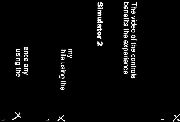


80

81


82


83

84
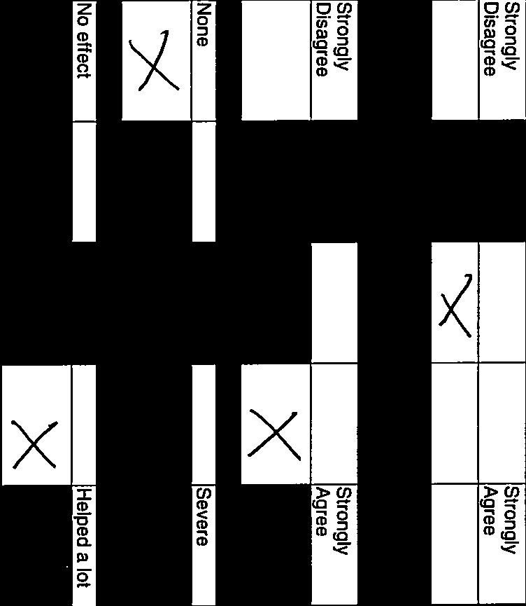

85


86


87


88


89
Best Practices for VR Applications
 Best Practices for VR Applications July 25 th, 2017 Wookho Son SW Content Research Laboratory Electronics&Telecommunications Research Institute Compliance with IEEE Standards Policies and Procedures Subclause
Virtual Reality I. Visual Imaging in the Electronic Age. Donald P. Greenberg November 9, 2017 Lecture #21
 Virtual Reality I Visual Imaging in the Electronic Age Donald P. Greenberg November 9, 2017 Lecture #21 1968: Ivan Sutherland 1990s: HMDs, Henry Fuchs 2013: Google Glass History of Virtual Reality 2016:
Intro to Virtual Reality (Cont)
") Lecture 37: Intro to Virtual Reality (Cont) Computer Graphics and Imaging UC Berkeley CS184/284A Overview of VR Topics Areas we will discuss over next few lectures VR Displays VR Rendering VR Imaging CS184/284A
Lecture 37: Intro to Virtual Reality (Cont) Computer Graphics and Imaging UC Berkeley CS184/284A Overview of VR Topics Areas we will discuss over next few lectures VR Displays VR Rendering VR Imaging CS184/284A
E90 Project Proposal. 6 December 2006 Paul Azunre Thomas Murray David Wright
 E90 Project Proposal 6 December 2006 Paul Azunre Thomas Murray David Wright Table of Contents Abstract 3 Introduction..4 Technical Discussion...4 Tracking Input..4 Haptic Feedack.6 Project Implementation....7
Interacting within Virtual Worlds (based on talks by Greg Welch and Mark Mine)
") Interacting within Virtual Worlds (based on talks by Greg Welch and Mark Mine) Presentation Working in a virtual world Interaction principles Interaction examples Why VR in the First Place? Direct perception
Interacting within Virtual Worlds (based on talks by Greg Welch and Mark Mine) Presentation Working in a virtual world Interaction principles Interaction examples Why VR in the First Place? Direct perception
Input devices and interaction. Ruth Aylett
 Input devices and interaction Ruth Aylett Contents Tracking What is available Devices Gloves, 6 DOF mouse, WiiMote Why is it important? Interaction is basic to VEs We defined them as interactive in real-time
Markerless 3D Gesture-based Interaction for Handheld Augmented Reality Interfaces
 Markerless 3D Gesture-based Interaction for Handheld Augmented Reality Interfaces Huidong Bai The HIT Lab NZ, University of Canterbury, Christchurch, 8041 New Zealand huidong.bai@pg.canterbury.ac.nz Lei
A Kinect-based 3D hand-gesture interface for 3D databases
 A Kinect-based 3D hand-gesture interface for 3D databases Abstract. The use of natural interfaces improves significantly aspects related to human-computer interaction and consequently the productivity
User Interfaces in Panoramic Augmented Reality Environments
 User Interfaces in Panoramic Augmented Reality Environments Stephen Peterson Department of Science and Technology (ITN) Linköping University, Sweden Supervisors: Anders Ynnerman Linköping University, Sweden
COPYRIGHTED MATERIAL. Overview
 In normal experience, our eyes are constantly in motion, roving over and around objects and through ever-changing environments. Through this constant scanning, we build up experience data, which is manipulated
Air Marshalling with the Kinect
 Air Marshalling with the Kinect Stephen Witherden, Senior Software Developer Beca Applied Technologies stephen.witherden@beca.com Abstract. The Kinect sensor from Microsoft presents a uniquely affordable
DepthTouch: Using Depth-Sensing Camera to Enable Freehand Interactions On and Above the Interactive Surface
 DepthTouch: Using Depth-Sensing Camera to Enable Freehand Interactions On and Above the Interactive Surface Hrvoje Benko and Andrew D. Wilson Microsoft Research One Microsoft Way Redmond, WA 98052, USA
Omni-Directional Catadioptric Acquisition System
 Technical Disclosure Commons Defensive Publications Series December 18, 2017 Omni-Directional Catadioptric Acquisition System Andreas Nowatzyk Andrew I. Russell Follow this and additional works at: http://www.tdcommons.org/dpubs_series
COPYRIGHTED MATERIAL OVERVIEW 1
 OVERVIEW 1 In normal experience, our eyes are constantly in motion, roving over and around objects and through ever-changing environments. Through this constant scanning, we build up experiential data,
Einführung in die Erweiterte Realität. 5. Head-Mounted Displays
 Einführung in die Erweiterte Realität 5. Head-Mounted Displays Prof. Gudrun Klinker, Ph.D. Institut für Informatik,Technische Universität München klinker@in.tum.de Nov 30, 2004 Agenda 1. Technological
Chapter 1 - Introduction
 1 "We all agree that your theory is crazy, but is it crazy enough?" Niels Bohr (1885-1962) Chapter 1 - Introduction Augmented reality (AR) is the registration of projected computer-generated images over
Potential Uses of Virtual and Augmented Reality Devices in Commercial Training Applications
 Potential Uses of Virtual and Augmented Reality Devices in Commercial Training Applications Dennis Hartley Principal Systems Engineer, Visual Systems Rockwell Collins April 17, 2018 WATS 2018 Virtual Reality
3D Interaction using Hand Motion Tracking. Srinath Sridhar Antti Oulasvirta
 3D Interaction using Hand Motion Tracking Srinath Sridhar Antti Oulasvirta EIT ICT Labs Smart Spaces Summer School 05-June-2013 Speaker Srinath Sridhar PhD Student Supervised by Prof. Dr. Christian Theobalt
AR 2 kanoid: Augmented Reality ARkanoid
 AR 2 kanoid: Augmented Reality ARkanoid B. Smith and R. Gosine C-CORE and Memorial University of Newfoundland Abstract AR 2 kanoid, Augmented Reality ARkanoid, is an augmented reality version of the popular
AUGMENTED VIRTUAL REALITY APPLICATIONS IN MANUFACTURING
 6 th INTERNATIONAL MULTIDISCIPLINARY CONFERENCE AUGMENTED VIRTUAL REALITY APPLICATIONS IN MANUFACTURING Peter Brázda, Jozef Novák-Marcinčin, Faculty of Manufacturing Technologies, TU Košice Bayerova 1,
The Impact of Dynamic Convergence on the Human Visual System in Head Mounted Displays
 The Impact of Dynamic Convergence on the Human Visual System in Head Mounted Displays by Ryan Sumner A thesis submitted to the Victoria University of Wellington in partial fulfilment of the requirements
VR-programming. Fish Tank VR. To drive enhanced virtual reality display setups like. Monitor-based systems Use i.e.
 VR-programming To drive enhanced virtual reality display setups like responsive workbenches walls head-mounted displays boomes domes caves Fish Tank VR Monitor-based systems Use i.e. shutter glasses 3D
Stereo-based Hand Gesture Tracking and Recognition in Immersive Stereoscopic Displays. Habib Abi-Rached Thursday 17 February 2005.
 Stereo-based Hand Gesture Tracking and Recognition in Immersive Stereoscopic Displays Habib Abi-Rached Thursday 17 February 2005. Objective Mission: Facilitate communication: Bandwidth. Intuitiveness.
Augmented and Virtual Reality
 CS-3120 Human-Computer Interaction Augmented and Virtual Reality Mikko Kytö 7.11.2017 From Real to Virtual [1] Milgram, P., & Kishino, F. (1994). A taxonomy of mixed reality visual displays. IEICE TRANSACTIONS
virtual reality SANJAY SINGH B.TECH (EC)
") virtual reality SINGH (EC) SANJAY B.TECH What is virtual reality? A satisfactory definition may be formulated like this: "Virtual Reality is a way for humans to visualize, manipulate and interact with
virtual reality SINGH (EC) SANJAY B.TECH What is virtual reality? A satisfactory definition may be formulated like this: "Virtual Reality is a way for humans to visualize, manipulate and interact with
Lecture 19: Depth Cameras. Kayvon Fatahalian CMU : Graphics and Imaging Architectures (Fall 2011)
") Lecture 19: Depth Cameras Kayvon Fatahalian CMU 15-869: Graphics and Imaging Architectures (Fall 2011) Continuing theme: computational photography Cheap cameras capture light, extensive processing produces
Lecture 19: Depth Cameras Kayvon Fatahalian CMU 15-869: Graphics and Imaging Architectures (Fall 2011) Continuing theme: computational photography Cheap cameras capture light, extensive processing produces
A Comparative Study of Structured Light and Laser Range Finding Devices
 A Comparative Study of Structured Light and Laser Range Finding Devices Todd Bernhard todd.bernhard@colorado.edu Anuraag Chintalapally anuraag.chintalapally@colorado.edu Daniel Zukowski daniel.zukowski@colorado.edu
CSE 190: Virtual Reality Technologies LECTURE #7: VR DISPLAYS
 CSE 190: Virtual Reality Technologies LECTURE #7: VR DISPLAYS Announcements Homework project 2 Due tomorrow May 5 at 2pm To be demonstrated in VR lab B210 Even hour teams start at 2pm Odd hour teams start
Image Manipulation Interface using Depth-based Hand Gesture
 Image Manipulation Interface using Depth-based Hand Gesture UNSEOK LEE JIRO TANAKA Vision-based tracking is popular way to track hands. However, most vision-based tracking methods can t do a clearly tracking
VR based HCI Techniques & Application. November 29, 2002
 VR based HCI Techniques & Application November 29, 2002 stefan.seipel@hci.uu.se What is Virtual Reality? Coates (1992): Virtual Reality is electronic simulations of environments experienced via head mounted
Virtual Reality in Neuro- Rehabilitation and Beyond
 Virtual Reality in Neuro- Rehabilitation and Beyond Amanda Carr, OTRL, CBIS Origami Brain Injury Rehabilitation Center Director of Rehabilitation Amanda.Carr@origamirehab.org Objectives Define virtual
Virtual Touch Human Computer Interaction at a Distance
 International Journal of Computer Science and Telecommunications [Volume 4, Issue 5, May 2013] 18 ISSN 2047-3338 Virtual Touch Human Computer Interaction at a Distance Prasanna Dhisale, Puja Firodiya,
VISUAL REQUIREMENTS ON AUGMENTED VIRTUAL REALITY SYSTEM
 Annals of the University of Petroşani, Mechanical Engineering, 8 (2006), 73-78 73 VISUAL REQUIREMENTS ON AUGMENTED VIRTUAL REALITY SYSTEM JOZEF NOVÁK-MARCINČIN 1, PETER BRÁZDA 2 Abstract: Paper describes
A Low Cost Optical See-Through HMD - Do-it-yourself
 2016 IEEE International Symposium on Mixed and Augmented Reality Adjunct Proceedings A Low Cost Optical See-Through HMD - Do-it-yourself Saul Delabrida Antonio A. F. Loureiro Federal University of Minas
Kinect Interface for UC-win/Road: Application to Tele-operation of Small Robots
 Kinect Interface for UC-win/Road: Application to Tele-operation of Small Robots Hafid NINISS Forum8 - Robot Development Team Abstract: The purpose of this work is to develop a man-machine interface for
CSE 190: 3D User Interaction
 Winter 2013 CSE 190: 3D User Interaction Lecture #4: Displays Jürgen P. Schulze, Ph.D. CSE190 3DUI - Winter 2013 Announcements TA: Sidarth Vijay, available immediately Office/lab hours: tbd, check web
Oculus Rift Introduction Guide. Version
 Oculus Rift Introduction Guide Version 0.8.0.0 2 Introduction Oculus Rift Copyrights and Trademarks 2017 Oculus VR, LLC. All Rights Reserved. OCULUS VR, OCULUS, and RIFT are trademarks of Oculus VR, LLC.
Diving into VR World with Oculus. Homin Lee Software Engineer at Oculus
 Diving into VR World with Oculus Homin Lee Software Engineer at Oculus Topics Who is Oculus Oculus Rift DK2 Positional Tracking SDK Latency Roadmap 1. Who is Oculus 1. Oculus is Palmer Luckey & John Carmack
Virtual Environments. Ruth Aylett
 Virtual Environments Ruth Aylett Aims of the course 1. To demonstrate a critical understanding of modern VE systems, evaluating the strengths and weaknesses of the current VR technologies 2. To be able
Development of excavator training simulator using leap motion controller
 Journal of Physics: Conference Series PAPER OPEN ACCESS Development of excavator training simulator using leap motion controller To cite this article: F Fahmi et al 2018 J. Phys.: Conf. Ser. 978 012034
Active Stereo Vision. COMP 4102A Winter 2014 Gerhard Roth Version 1
 Active Stereo Vision COMP 4102A Winter 2014 Gerhard Roth Version 1 Why active sensors? Project our own texture using light (usually laser) This simplifies correspondence problem (much easier) Pluses Can
Rendering Challenges of VR
 Lecture 27: Rendering Challenges of VR Computer Graphics CMU 15-462/15-662, Fall 2015 Virtual reality (VR) vs augmented reality (AR) VR = virtual reality User is completely immersed in virtual world (sees
Virtual Reality and Natural Interactions
 Virtual Reality and Natural Interactions Jackson Rushing Game Development and Entrepreneurship Faculty of Business and Information Technology j@jacksonrushing.com 2/23/2018 Introduction Virtual Reality
Virtual Reality Devices in C2 Systems
 Jan Hodicky, Petr Frantis University of Defence Brno 65 Kounicova str. Brno Czech Republic +420973443296 jan.hodicky@unbo.cz petr.frantis@unob.cz Virtual Reality Devices in C2 Systems Topic: Track 8 C2
MULTIPLE SENSORS LENSLETS FOR SECURE DOCUMENT SCANNERS
 INFOTEH-JAHORINA Vol. 10, Ref. E-VI-11, p. 892-896, March 2011. MULTIPLE SENSORS LENSLETS FOR SECURE DOCUMENT SCANNERS Jelena Cvetković, Aleksej Makarov, Sasa Vujić, Vlatacom d.o.o. Beograd Abstract -
Natural Gesture Based Interaction for Handheld Augmented Reality
 Natural Gesture Based Interaction for Handheld Augmented Reality A thesis submitted in partial fulfilment of the requirements for the Degree of Master of Science in Computer Science By Lei Gao Supervisors:
Enabling Cursor Control Using on Pinch Gesture Recognition
 Enabling Cursor Control Using on Pinch Gesture Recognition Benjamin Baldus Debra Lauterbach Juan Lizarraga October 5, 2007 Abstract In this project we expect to develop a machine-user interface based on
LOOKING AHEAD: UE4 VR Roadmap. Nick Whiting Technical Director VR / AR
 LOOKING AHEAD: UE4 VR Roadmap Nick Whiting Technical Director VR / AR HEADLINE AND IMAGE LAYOUT RECENT DEVELOPMENTS RECENT DEVELOPMENTS At Epic, we drive our engine development by creating content. We
Step. A Big Step Forward for Virtual Reality
 Step A Big Step Forward for Virtual Reality Advisor: Professor Goeckel 1 Team Members Ryan Daly Electrical Engineer Jared Ricci Electrical Engineer Joseph Roberts Electrical Engineer Steven So Electrical
Classifying 3D Input Devices
 IMGD 5100: Immersive HCI Classifying 3D Input Devices Robert W. Lindeman Associate Professor Department of Computer Science Worcester Polytechnic Institute gogo@wpi.edu Motivation The mouse and keyboard
Pinch-the-Sky Dome: Freehand Multi-Point Interactions with Immersive Omni-Directional Data
 Pinch-the-Sky Dome: Freehand Multi-Point Interactions with Immersive Omni-Directional Data Hrvoje Benko Microsoft Research One Microsoft Way Redmond, WA 98052 USA benko@microsoft.com Andrew D. Wilson Microsoft
Special Topic: Virtual Reality
 Lecture 24: Special Topic: Virtual Reality Computer Graphics and Imaging UC Berkeley CS184/284A, Spring 2016 Credit: Kayvon Fatahalian created the majority of these lecture slides Virtual Reality (VR)
/ Impact of Human Factors for Mixed Reality contents: / # How to improve QoS and QoE? #
 / Impact of Human Factors for Mixed Reality contents: / # How to improve QoS and QoE? # Dr. Jérôme Royan Definitions / 2 Virtual Reality definition «The Virtual reality is a scientific and technical domain
Gesture Recognition with Real World Environment using Kinect: A Review
 Gesture Recognition with Real World Environment using Kinect: A Review Prakash S. Sawai 1, Prof. V. K. Shandilya 2 P.G. Student, Department of Computer Science & Engineering, Sipna COET, Amravati, Maharashtra,
Capacitive Face Cushion for Smartphone-Based Virtual Reality Headsets
 Technical Disclosure Commons Defensive Publications Series November 22, 2017 Face Cushion for Smartphone-Based Virtual Reality Headsets Samantha Raja Alejandra Molina Samuel Matson Follow this and additional
Geo-Located Content in Virtual and Augmented Reality
 Technical Disclosure Commons Defensive Publications Series October 02, 2017 Geo-Located Content in Virtual and Augmented Reality Thomas Anglaret Follow this and additional works at: http://www.tdcommons.org/dpubs_series
Haptic control in a virtual environment
 Haptic control in a virtual environment Gerard de Ruig (0555781) Lourens Visscher (0554498) Lydia van Well (0566644) September 10, 2010 Introduction With modern technological advancements it is entirely
VIRTUAL REALITY LAB Research group Softwarevisualisation in 3D and VR
 VIRTUAL REALITY LAB Research group Softwarevisualisation in 3D and VR softvis@uni-leipzig.de http://home.uni-leipzig.de/svis/vr-lab/ VR Labor Hardware Portfolio OVERVIEW HTC Vive Oculus Rift Leap Motion
Chapter 1 Virtual World Fundamentals
 Chapter 1 Virtual World Fundamentals 1.0 What Is A Virtual World? {Definition} Virtual: to exist in effect, though not in actual fact. You are probably familiar with arcade games such as pinball and target
Quality of Experience for Virtual Reality: Methodologies, Research Testbeds and Evaluation Studies
 Quality of Experience for Virtual Reality: Methodologies, Research Testbeds and Evaluation Studies Mirko Sužnjević, Maja Matijašević This work has been supported in part by Croatian Science Foundation
tracker hardware data in tracker CAVE library coordinate system calibration table corrected data in tracker coordinate system
 Line of Sight Method for Tracker Calibration in Projection-Based VR Systems Marek Czernuszenko, Daniel Sandin, Thomas DeFanti fmarek j dan j tomg @evl.uic.edu Electronic Visualization Laboratory (EVL)
High Performance Imaging Using Large Camera Arrays
 High Performance Imaging Using Large Camera Arrays Presentation of the original paper by Bennett Wilburn, Neel Joshi, Vaibhav Vaish, Eino-Ville Talvala, Emilio Antunez, Adam Barth, Andrew Adams, Mark Horowitz,
Eric Chae Phong Lai Eric Pantaleon Ajay Reddy CPE 322 Engineering Design 6 Assignment 5
 Eric Chae Phong Lai Eric Pantaleon Ajay Reddy CPE 322 Engineering Design 6 Assignment 5 Section 1 Research on this project was divided into four distinct areas: 3D audio recording, audio processing and
International Journal of Advance Engineering and Research Development. Surface Computer
 Scientific Journal of Impact Factor (SJIF): 4.72 International Journal of Advance Engineering and Research Development Volume 4, Issue 4, April -2017 Surface Computer Sureshkumar Natarajan 1,Hitesh Koli
What was the first gestural interface?
 stanford hci group / cs247 Human-Computer Interaction Design Studio What was the first gestural interface? 15 January 2013 http://cs247.stanford.edu Theremin Myron Krueger 1 Myron Krueger There were things
PROGRESS ON THE SIMULATOR AND EYE-TRACKER FOR ASSESSMENT OF PVFR ROUTES AND SNI OPERATIONS FOR ROTORCRAFT
 PROGRESS ON THE SIMULATOR AND EYE-TRACKER FOR ASSESSMENT OF PVFR ROUTES AND SNI OPERATIONS FOR ROTORCRAFT 1 Rudolph P. Darken, 1 Joseph A. Sullivan, and 2 Jeffrey Mulligan 1 Naval Postgraduate School,
Lenses- Worksheet. (Use a ray box to answer questions 3 to 7)
") Lenses- Worksheet 1. Look at the lenses in front of you and try to distinguish the different types of lenses? Describe each type and record its characteristics. 2. Using the lenses in front of you, look
Lenses- Worksheet 1. Look at the lenses in front of you and try to distinguish the different types of lenses? Describe each type and record its characteristics. 2. Using the lenses in front of you, look
Head Tracking for Google Cardboard by Simond Lee
 Head Tracking for Google Cardboard by Simond Lee (slee74@student.monash.edu) Virtual Reality Through Head-mounted Displays A head-mounted display (HMD) is a device which is worn on the head with screen
Virtual Co-Location for Crime Scene Investigation and Going Beyond
 Virtual Co-Location for Crime Scene Investigation and Going Beyond Stephan Lukosch Faculty of Technology, Policy and Management, Systems Engineering Section Delft University of Technology Challenge the
- applications on same or different network node of the workstation - portability of application software - multiple displays - open architecture
 12 Window Systems - A window system manages a computer screen. - Divides the screen into overlapping regions. - Each region displays output from a particular application. X window system is widely used
Multi variable strategy reduces symptoms of simulator sickness
 Multi variable strategy reduces symptoms of simulator sickness Jorrit Kuipers Green Dino BV, Wageningen / Delft University of Technology 3ME, Delft, The Netherlands, jorrit@greendino.nl Introduction Interactive
VICs: A Modular Vision-Based HCI Framework
 VICs: A Modular Vision-Based HCI Framework The Visual Interaction Cues Project Guangqi Ye, Jason Corso Darius Burschka, & Greg Hager CIRL, 1 Today, I ll be presenting work that is part of an ongoing project
Enhancing Shipboard Maintenance with Augmented Reality
 Enhancing Shipboard Maintenance with Augmented Reality CACI Oxnard, CA Dennis Giannoni dgiannoni@caci.com (805) 288-6630 INFORMATION DEPLOYED. SOLUTIONS ADVANCED. MISSIONS ACCOMPLISHED. Agenda Virtual
DESIGN STYLE FOR BUILDING INTERIOR 3D OBJECTS USING MARKER BASED AUGMENTED REALITY
 DESIGN STYLE FOR BUILDING INTERIOR 3D OBJECTS USING MARKER BASED AUGMENTED REALITY 1 RAJU RATHOD, 2 GEORGE PHILIP.C, 3 VIJAY KUMAR B.P 1,2,3 MSRIT Bangalore Abstract- To ensure the best place, position,
VR System Input & Tracking
 Human-Computer Interface VR System Input & Tracking 071011-1 2017 년가을학기 9/13/2017 박경신 System Software User Interface Software Input Devices Output Devices User Human-Virtual Reality Interface User Monitoring
IMAGE FORMATION. Light source properties. Sensor characteristics Surface. Surface reflectance properties. Optics
 IMAGE FORMATION Light source properties Sensor characteristics Surface Exposure shape Optics Surface reflectance properties ANALOG IMAGES An image can be understood as a 2D light intensity function f(x,y)
Determining Optimal Player Position, Distance, and Scale from a Point of Interest on a Terrain
 Technical Disclosure Commons Defensive Publications Series October 02, 2017 Determining Optimal Player Position, Distance, and Scale from a Point of Interest on a Terrain Adam Glazier Nadav Ashkenazi Matthew
Computer Graphics. Spring April Ghada Ahmed, PhD Dept. of Computer Science Helwan University
 Spring 2018 10 April 2018, PhD ghada@fcih.net Agenda Augmented reality (AR) is a field of computer research which deals with the combination of real-world and computer-generated data. 2 Augmented reality
Application of 3D Terrain Representation System for Highway Landscape Design
 Application of 3D Terrain Representation System for Highway Landscape Design Koji Makanae Miyagi University, Japan Nashwan Dawood Teesside University, UK Abstract In recent years, mixed or/and augmented
Haptic presentation of 3D objects in virtual reality for the visually disabled
 Haptic presentation of 3D objects in virtual reality for the visually disabled M Moranski, A Materka Institute of Electronics, Technical University of Lodz, Wolczanska 211/215, Lodz, POLAND marcin.moranski@p.lodz.pl,
Health & Safety
 Health & Safety http://www.etc.cmu.edu/projects/gotan/wp-content/uploads/warnings.pdf HEALTH & SAFETY WARNINGS: Please ensure that all users of the headset read the warnings below carefully before using
State Of The Union.. Past, Present, And Future Of Wearable Glasses. Salvatore Vilardi V.P. of Product Development Immy Inc.
 State Of The Union.. Past, Present, And Future Of Wearable Glasses Salvatore Vilardi V.P. of Product Development Immy Inc. Salvatore Vilardi Mobile Monday October 2016 1 Outline 1. The Past 2. The Present
Real-Time Face Detection and Tracking for High Resolution Smart Camera System
 Digital Image Computing Techniques and Applications Real-Time Face Detection and Tracking for High Resolution Smart Camera System Y. M. Mustafah a,b, T. Shan a, A. W. Azman a,b, A. Bigdeli a, B. C. Lovell
Design and Development of a Marker-based Augmented Reality System using OpenCV and OpenGL
 Design and Development of a Marker-based Augmented Reality System using OpenCV and OpenGL Yap Hwa Jentl, Zahari Taha 2, Eng Tat Hong", Chew Jouh Yeong" Centre for Product Design and Manufacturing (CPDM).
23270: AUGMENTED REALITY FOR NAVIGATION AND INFORMATIONAL ADAS. Sergii Bykov Technical Lead Machine Learning 12 Oct 2017
 23270: AUGMENTED REALITY FOR NAVIGATION AND INFORMATIONAL ADAS Sergii Bykov Technical Lead Machine Learning 12 Oct 2017 Product Vision Company Introduction Apostera GmbH with headquarter in Munich, was
CSC Stereography Course I. What is Stereoscopic Photography?... 3 A. Binocular Vision Depth perception due to stereopsis
 CSC Stereography Course 101... 3 I. What is Stereoscopic Photography?... 3 A. Binocular Vision... 3 1. Depth perception due to stereopsis... 3 2. Concept was understood hundreds of years ago... 3 3. Stereo
VisionGauge OnLine Standard Edition Spec Sheet
 VisionGauge OnLine Standard Edition Spec Sheet VISIONx INC. www.visionxinc.com Powerful & Easy to Use Intuitive Interface VisionGauge OnLine is a powerful and easy-to-use machine vision software for automated
Robust Hand Gesture Recognition for Robotic Hand Control
 Robust Hand Gesture Recognition for Robotic Hand Control Ankit Chaudhary Robust Hand Gesture Recognition for Robotic Hand Control 123 Ankit Chaudhary Department of Computer Science Northwest Missouri State
EnSight in Virtual and Mixed Reality Environments
 CEI 2015 User Group Meeting EnSight in Virtual and Mixed Reality Environments VR Hardware that works with EnSight Canon MR Oculus Rift Cave Power Wall Canon MR MR means Mixed Reality User looks through
iwindow Concept of an intelligent window for machine tools using augmented reality
 iwindow Concept of an intelligent window for machine tools using augmented reality Sommer, P.; Atmosudiro, A.; Schlechtendahl, J.; Lechler, A.; Verl, A. Institute for Control Engineering of Machine Tools
Development of a Novel Low-Cost Flight Simulator for Pilot Training
 Development of a Novel Low-Cost Flight Simulator for Pilot Training Hongbin Gu, Dongsu Wu, and Hui Liu Abstract A novel low-cost flight simulator with the development goals cost effectiveness and high
pcon.planner PRO Plugin VR-Viewer
 pcon.planner PRO Plugin VR-Viewer Manual Dokument Version 1.2 Author DRT Date 04/2018 2018 EasternGraphics GmbH 1/10 pcon.planner PRO Plugin VR-Viewer Manual Content 1 Things to Know... 3 2 Technical Tips...
Dual-fisheye Lens Stitching for 360-degree Imaging & Video. Tuan Ho, PhD. Student Electrical Engineering Dept., UT Arlington
 Dual-fisheye Lens Stitching for 360-degree Imaging & Video Tuan Ho, PhD. Student Electrical Engineering Dept., UT Arlington Introduction 360-degree imaging: the process of taking multiple photographs and
ReVRSR: Remote Virtual Reality for Service Robots
 ReVRSR: Remote Virtual Reality for Service Robots Amel Hassan, Ahmed Ehab Gado, Faizan Muhammad March 17, 2018 Abstract This project aims to bring a service robot s perspective to a human user. We believe
Virtual Reality. Lecture #11 NBA 6120 Donald P. Greenberg September 30, 2015
 Virtual Reality Lecture #11 NBA 6120 Donald P. Greenberg September 30, 2015 Virtual Reality What is Virtual Reality? Virtual Reality A term used to describe a computer generated environment which can simulate
Development of a Finger Mounted Type Haptic Device Using a Plane Approximated to Tangent Plane
 Journal of Communication and Computer 13 (2016) 329-337 doi:10.17265/1548-7709/2016.07.002 D DAVID PUBLISHING Development of a Finger Mounted Type Haptic Device Using a Plane Approximated to Tangent Plane
CSE 165: 3D User Interaction. Lecture #14: 3D UI Design
 CSE 165: 3D User Interaction Lecture #14: 3D UI Design 2 Announcements Homework 3 due tomorrow 2pm Monday: midterm discussion Next Thursday: midterm exam 3D UI Design Strategies 3 4 Thus far 3DUI hardware
MEASURING AND ANALYZING FINE MOTOR SKILLS
 MEASURING AND ANALYZING FINE MOTOR SKILLS PART 1: MOTION TRACKING AND EMG OF FINE MOVEMENTS PART 2: HIGH-FIDELITY CAPTURE OF HAND AND FINGER BIOMECHANICS Abstract This white paper discusses an example
MECHANICAL DESIGN LEARNING ENVIRONMENTS BASED ON VIRTUAL REALITY TECHNOLOGIES
 INTERNATIONAL CONFERENCE ON ENGINEERING AND PRODUCT DESIGN EDUCATION 4 & 5 SEPTEMBER 2008, UNIVERSITAT POLITECNICA DE CATALUNYA, BARCELONA, SPAIN MECHANICAL DESIGN LEARNING ENVIRONMENTS BASED ON VIRTUAL
OCULUS VR, LLC. Oculus User Guide Runtime Version Rev. 1
 OCULUS VR, LLC Oculus User Guide Runtime Version 0.4.0 Rev. 1 Date: July 23, 2014 2014 Oculus VR, LLC All rights reserved. Oculus VR, LLC Irvine, CA Except as otherwise permitted by Oculus VR, LLC, this