Mold Design. 5. Mold Structure. Bong-Kee Lee School of Mechanical Engineering Chonnam National University
|
|
|
- Ezra Damian Wilkinson
- 6 years ago
- Views:
Transcription

1 5. Mold Structure Bong-Kee Lee Chonnam National University the simplest and most reliable design has the fewest number of moving parts and is more straightforward to manufacture and run in production is usually cheaper to manufacture
2 Basic Two-Plate Construction Basic General Arrangement


3 locating or register ring circular ring, screwed to the front clamping plate enables the mold to be centered on the injection cylinder axis by locating it into a machined hole in the stationary platen good-quality low-carbon steel top plate or, front plate, fixed half front plate, fixed half clamping plate allows the mold to be secured to the fixed platen with cap screws to hole it in position low-carbon steel or alloy tool steel for very long-running jobs
4 split line or, parting line plane or position at which the mold separates into two distinct parts stationary and moving platens after the mold has split at this point, space is created for the molded parts to be pushed or ejected from the mold cavity insert or, mold insert, insert core circular or rectangular piece of alloy tool steel that carried the form of the molded part in it more convenient machining and prevention of distortion from the hardening
5 front cavity plate or, fixed half cavity plate to hold the front half cavity inserts in position in the stationary platen of the mold low-carbon steel or alloy steel for very long-running jobs rear cavity plate the same function and material as the front cavity plate makes the rear half inserts captive between it and the cavity support plate cavity support plate to withstand the force generated by the injection pressure of the melt that is exerted on the actual cavity parts alloy tool steel to resist the cavity inserts being embedded (or hobbed) into it must be of sufficient depth (or thickness) to prevent excessive plate deflection taking place
6 ejection system carries a number of ejection pins that push or eject the parts from the cavities as well as ejector pins, it may use sleeve ejectors and blade ejectors or may also operate stripper plates, double ejection systems, collapsible cores or other more complex devices ejection gap the amount that the ejector system can move towards the cavity support plate from its rest position support blocks or, risers connects the cavity support plate to the rear clamping plate or back plate good-quality low-carbon steel


7 guide pillar accurately align the front and rear platens of the mold hardened alloy tool steel return pins or, push backs to return the ejection system to its initial or rest position when the tool closes to prevent any damage to the more fragile ejector pins through contact with the front platen of the mold hardened silver steel or hardened alloy steel

8 Detailed Design Detailed Design additional features clearances around the ejection pins, ejector return pins and ejector bar bushes on guide pillars and return pins wears between the mold plates of soft mild or alloy steel and the repeated sliding of hardened components screws to hole the tool together support pillars taper tapped holes on water cooling channels stand-off buttons beneath the ejector system chamfers on rectangular cavity insert guide pillar and bush system completely aligns the mold


9 Multi-Plate Mold when an over feed gate is necessary, either for multipoint feeding parts or for gating parts to achieve balanced flow Multi-Plate Mold operation stages gate breaking or de-gating stage

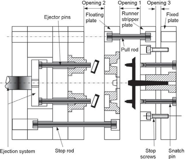
10 Multi-Plate Mold operation stages Multi-Plate Mold operation stages

11 Multi-Plate Mold disadvantages long opening stroke is necessary to accommodate all the different openings both the speed and accuracy of the mold open stop must be good as variations in either can results in the failure of the mold to operate or, worse, in a breakage the limiting factor on most molds is nearly always the length of opening stroke required Multi-Plate Mold incorrect opening sequence
12 Multi-Plate Mold main requirements it must open in such a way that all possibilities of the molded parts sticking in the cavities are avoided the openings must be sufficient to ensure the runner, sprue, and the parts have sufficient room to fall freely from the mold the molding machine must have an accurate opening stroke, otherwise the pull rods and limit bolts may be broken or the parts and the runner system may not be stripped and ejected properly Multi-Plate Mold comparison with hot runner systems suitable for medium-length production runs, where the relatively higher cost of the hot runner mold would not be economic often more reliable owing to simpler nature and does not require expensive heating and control systems changing material and/or color is easier since this type of mold clears its complete feed system every shot thermal sensitivity of certain material such as PVC or acetals may prohibit the use of hot runner systems

13 Multi-Plate Mold for Drive Gear Multi-Plate Mold Multi-Plate Undercut Molds injection mold for valve housings


14 Multi-Plate Mold Multi-Plate Undercut Molds Multi-Plate Mold Stack Molds highly efficient, cost-effective production method of large projected areas shallow boxes, cassette cases, video cases, and Petri dishes alignment of projected areas in stack molds

15 Multi-Plate Mold Stack Molds simple design of stack molds
PROVIDENT DESIGN CHECKLIST
 PROVIDET PROCUREMET WWW.PROVPROCURE.COM PLASTIC IJECTIO MOLD DESIG CHECKLIST MOLD DESIG CHECKLIST PROVIDET PROCUREMET ITRODUCTIO Before you start with a new Mold you need to get as MUCH information on
Design of Singe Impression Injection Mould for Lower Bearing Cover
 Design of Singe Impression Injection Mould for Lower Bearing Cover Vishwanath DC Student, M. Tech Government Tool Room and Training Centre Mysuru, India Abstract Injection moulding is one of the techniques
.01 undercut. Ø.187 locating dowel hole (Ø.1875 x.50 pin included)
") Mold Components 1 SPRUE BUSHINGS Made of AISI 6150 material; precision ground; polished I.D. Hardened to Rc 46-50 Dowel pin hole in head for locating (pin included) Radius under head with undercut to reduce
Mold Components 1 SPRUE BUSHINGS Made of AISI 6150 material; precision ground; polished I.D. Hardened to Rc 46-50 Dowel pin hole in head for locating (pin included) Radius under head with undercut to reduce
DESIGN AND DEVELOPMENT OF MOULD CALCULATION SOFTWARE MUHAMAD IDZWAN BIN LATIF
 DESIGN AND DEVELOPMENT OF MOULD CALCULATION SOFTWARE MUHAMAD IDZWAN BIN LATIF Report submitted in partial fulfillment of the requirements for the award of Bachelor of Manufacturing Engineering Faculty
This is trial version
 Guiding components, Locating units, Dowel pins, Screws, Springs, Dateand recycling inserts, Retaining rings, Lifting devices, Clamping-systems, Thermal insulating sheets, Locating rings 1.01 1.02 Ordering
Vardhman Dies And Mould Tools
 +91-8048762549 Vardhman Dies And Mould Tools https://www.mouldtoolsindia.com/ Renowned manufacturers of HSS Piercing Punches, Ejector Pins, Molding Tools that are fabricated from high grade metal & alloys.
Example 33, Three-Plate Injection Mold with Stripping Device for a Precision Magazine
 88 3 Examples Example 33 Example 33, Three-Plate Injection Mold with Stripping Device for a Precision Magazine Integrated circuits (IC) are generally mounted automatically during production of electronic
Dual clip mould In the following exercise you will create a full 2 cavity mould of your dual clip mould component.
 Dual clip mould 2018 In the following exercise you will create a full 2 cavity mould of your dual clip mould component. The mould is required to be a 2 cavity mould and must contain all the necessary detail
AGS TOOL #: DESCRIPTION: TOOL SHOP: *Changes or clarifications from 10/07/08 revision are highlighted in red. SECTION I: PLAQUES
 Required AGS TOOL #: DESCRIPTION: TOOL SHOP: *Changes or clarifications from 1/7/8 revision are highlighted in red. SECTION I: PLAQUES 1) Mold identification plaque: Mount on the operator side of the mold,
Trade of Toolmaking. Module 5: Press Tools, Jigs & Fixtures, Mouldmaking Unit 10: Mould Assembly Phase 2. Published by
 Trade of Toolmaking Module 5: Press Tools, Jigs & Fixtures, Mouldmaking Unit 10: Mould Assembly Phase 2 Published by SOLAS 2014 Unit 9 1 Table of Contents Document Release History... 3 Unit Objective...
Trade of Toolmaking. Module 5: Press Tools, Jigs & Fixtures, Mouldmaking Unit 7: Injection Moulds Phase 2. Published by
 Trade of Toolmaking Module 5: Press Tools, Jigs & Fixtures, Mouldmaking Unit 7: Injection Moulds Phase 2 Published by SOLAS 2014 Unit 7 1 Table of Contents Document Release History... 3 Unit Objective...
Tooling Approving Report
 Project Name: Part Name: Tool Name: Tool source: Tool Steel: Resin: Project Number: Part Number: Tool Number: Customer: No of Cavities: Machine Size: CAVITY What is the customer required core hardness?
RJG Mold Deflection Sensor Installation and Use
 when mold is open RJG Mold Deflection Sensor Installation and Use RJG s Mold Deflection sensor measures how much the mold parting line has opened on each cycle. The sensor mounts in the clamp plate with
D E S I G N A N D M A N U F A C T U R E : C O U R S E M A T E R I A L
 UNIT D E S I G N A N D M A N U F A C T U R E : C O U R S E M A T E R I A L metalwork processes Screw Threads The screw thread is a very important detail in engineering. It is used to hold parts together.
DESIGN & ASSEMBLY GUIDE. D-M-E Collapsible Core and Collapsible Mini-Core
 DESIGN & ASSEMBLY GUIDE D-M-E Collapsible Core and Collapsible Mini-Core TABLE OF CONTENTS D-M-E Collapsible Core & Collapsible Mini-Core This data is designed to assist you in using the D-M-E Collapsible
Mould Precision Co., Ltd
 Program Name: Part Name: Tool Name: Tool Source: Tool Steel: Resin: NL9502 314501 MP1425 Mould Precision Co., Ltd Finished Mould Checklist H13 HRC 48-52 ABS HF380(LG Chem) Program No.: Part No.: Tool No.:
Mould Precision Co., Ltd
 Mould Precision Co., Ltd Program Name: Part Name: Tool Name: Tool source: Tool Steel: Resin: Finished Mould Checklist Program No.: MP15016 NL00326-2G rev04 Part No.: MP15016 Tool No.: MP15016 Customer:
Chapter 1 Sand Casting Processes
 Chapter 1 Sand Casting Processes Sand casting is a mold based net shape manufacturing process in which metal parts are molded by pouring molten metal into a cavity. The mold cavity is created by withdrawing
Mold Making THE MOLDING PROCESS
 1 Mold Making THE MOLDING PROCESS As you know, the lost-wax casting process uses wax models for casting. The mold you make will be used to make a large quantity of these models. A properly made mold will
Design Guidelines for Injection Molding
 Design Guidelines for Injection Molding TABLE OF CONTENTS INTRODUCTION TO INJECTION MOLDING A. Where is it used? B. Importance of prototyping C. Types of prototypes INJECTION MOLDING BASICS A. The machine
Gastrow Injection Molds
 Paul Unger (Ed.) Gastrow Injection Molds Sample Chapter 1: Principles of Mold Design ISBNs 978-1-56990-402-2 1-56990-402-2 HANSER Hanser Publishers, Munich Hanser Publications, Cincinnati 1.1 Types of
University of Arizona College of Optical Sciences
 University of Arizona College of Optical Sciences Name: Nachiket Kulkarni Course: OPTI521 Topic Plastic Injection Molding Submitted to Prof. J. Burge Date 1. Introduction In daily life, we come across
All About Die Casting
 All About Die Casting FAQ Introduction Die casting is a versatile process for producing engineered metal parts by forcing molten metal under high pressure into reusable steel molds. These molds, called
Design and Analysis of Progressive Die for Chain Link Plate
 Design and Analysis of Progressive Die for Chain Link Plate Md Inaithul Rehaman #1, P Satish Reddy #2, Matta Manoj #3, N.Guru Murthy #4 ME Department, Prasiddha College of Engg and Technology, Anathavaram
DESIGN AND DEVELOPMENT OF FAMILY INJECTION MOULD FOR INNOVATIVE PLASTIC IN AND INNOVATIVE PLASTIC OUT
 International Journal of Emerging Technology and Innovative Engineering Volume 1, Issue 9, September 2015 (ISSN: 2394 6598) DESIGN AND DEVELOPMENT OF FAMILY INJECTION MOULD FOR INNOVATIVE PLASTIC IN AND
This Injection Mold Standard is used for the design and fabrication of Plastic Injection Molds.
 This Injection Mold Standard is used for the design and fabrication of Plastic Injection Molds. 1. Mold Design 1.1. A preliminary mold design review will be conducted, preferably with the customer present,
The jigs and fixtures are the economical ways to produce a component in mass production system. These are special work holding and tool guiding device
 The jigs and fixtures are the economical ways to produce a component in mass production system. These are special work holding and tool guiding device Quality of the performance of a process largely influenced
Operating & Maintenance Instructions 25 Injection Moulding Machine
 Operating & Maintenance Instructions 25 Injection Moulding Machine Table of Contents 1. Health and Safety Information... 2 2. Upon Receipt... 2 3a. Temperature Controller Settings (Brainchild Controller)...
Parting Line Best Practices for Injection molded parts. Cusanno, Bergadano TAG, Engineering Quality & Craftsmanship
 Parting Line Best Practices for Injection molded parts Cusanno, Bergadano TAG, Engineering Quality & Craftsmanship 20 Novembre, 2010 What is Zero Parting Line Execution? Primarily a Design Standard in
Two Categories of Metal Casting Processes
 Two Categories of Metal Casting Processes 1. Expendable mold processes - mold is sacrificed to remove part Advantage: more complex shapes possible Disadvantage: production rates often limited by time to
Design of Jigs, Fixtures, Press Tools and Moulds UNIT - 1 LOCATING AND CLAMPING PRINCIPLES
 Design of Jigs, Fixtures, Press Tools and Moulds UNIT - 1 LOCATING AND CLAMPING PRINCIPLES 1. Define the term Tool design. Tool design is the process of designing and developing the tools, methods, and
Permanent Mold Casting Processes. Assoc Prof Zainal Abidin Ahmad Department of Manufacturing & Ind. Eng.
 Assoc Prof Zainal Abidin Ahmad Department of Manufacturing & Ind. Eng. Universiti Teknologi Malaysia Permanent Mold Casting Processes Gravity die casting Pressure die casting Low pressure High pressure
DO35 MAINTENANCE INSTRUCTIONS
 CUSTOMER INFORMATION SHEET NO. 038 DO35 MAINTENANCE INSTRUCTIONS (DO35 V3 LAUNCHED PRODUCTION JUNE 2017) Table of Contents 1.0 Replacing Spindle Bushes V3... 22 2.0 Replacing Locking Mechanism V3... 6
HARDINGE Installation booklet For: Dead-Length Collet Adaptation Chucks Stationary Collet
 HARDINGE Installation booklet For: Dead-Length Collet Adaptation Chucks Stationary Collet Read the enclosed instructions and recommendations before any installations CONTENTS Dead-Length Collet Adaptation
1) Place the magazine cut-off in the center position between off and on (as shown in figure 1). 2) Remove the bolt.
 Place the magazine cut-off in the center position between off and on (as shown in figure 1). 2) Remove the bolt.") 1) Place the magazine cut-off in the center position between off and on (as shown in figure 1). 2) Remove the bolt. 3) Unscrew upper band screw. 4) Remove the upper band screw. 5) Loosen the stacking swivel
1) Place the magazine cut-off in the center position between off and on (as shown in figure 1). 2) Remove the bolt. 3) Unscrew upper band screw. 4) Remove the upper band screw. 5) Loosen the stacking swivel
Selecting Injection Molds
 Selecting Injection Molds Herbert Rees, Bruce Catoen Weighing Cost vs Productivity ISBN 3-446-40308-6 Leseprobe Weitere Informationen oder Bestellungen unter http://www.hanser.de/3-446-40308-6 sowie im
Injection Molding Principles
 Injection Molding Principles R&D Center 1. What is injection molding? Most engineering plastics are being manufactured by injection molding and it is important to understand both its procedures and precautions.
Name: Class: Teacher:..
 Name: Class: Teacher:.. 1 Metals All metals in use today are either PURE METALS or ALLOYS. Copper, iron, tin, lead, gold and silver are all examples of PURE METALS which have been mined from the Earth
CHAPTER 5: MOULDING PROCESS
 CHAPTER OUTLINE CHAPTER 5: MOULDING PROCESS 5.1 INTRODUCTION 5.2 INJECTION MOULDING 5.3 COMPRESSION AND TRANSFER MOLDING 5.4 BLOW AND ROTATIONAL MOLDING 5.5 PRODUCT DESIGN CONSIDERATIONS 1 5.1 Introduction
Special reamers. Figure N 1 Reamer with descending cutting edges in carbide (Cerin)
") Special reamers There is a wide category of special reamers, ie non-standard, that are suitable to address particular problems encountered in the finishing holes, both for maintenance of individual pieces
Special reamers There is a wide category of special reamers, ie non-standard, that are suitable to address particular problems encountered in the finishing holes, both for maintenance of individual pieces
SUBMITTED BY: MANEET KOHLI ROLL NO.
 SUBMITTED BY: MANEET KOHLI ROLL NO. 11 INJECTION MOLDING Injection molding is nowadays the most popular method to produce 3-dimensional parts of different kinds of polymeric materials. It is a fast process
CHAPTER 4: METAL CASTING PROCESS
 CHAPTER 4: METAL CASTING PROCESS CHAPTER OUTLINE 4.1 INTRODUCTION 4.2 EXPANDABLE MOLD CASTING PROCESSES 4.2.1 Sand Casting 4.2.2 Shell Molding 4.2.3 Plaster Mold Casting 4.2.4 Ceramic Mold Casting 4.2.5
HAND SHEARS NO. 12 AND NO. 24
 OPERATOR S MANUAL & INSTRUCTIONS HAND SHEARS NO. AND NO. Di-Acro, Incorporated PO Box 9700 Canton, Ohio 7 7 Progress Street N.E. Canton, Ohio 70 0--9 0--00 (fax) Revised 0/0 Sale or distribution of manuals
HARDINGE Installation booklet For:
 HARDINGE Installation booklet For: L Flange Nose Dead-Length Collet Adaptation Chucks Draw Collet Read the enclosed instructions and recommendations before any installations WARRANTY & RETURN PROCEDURES
- sprue gate - pinpoint gate - fan gate - tunnel gate
 Moulds for processing of thermosetting moulding compounds 1. Sprue and Runner Systems and Gates Sprues should have either a round cross-section or a rounded trapezoidal construction and must have well-polished
INJECTION MOULDING OF PLASTICS INJECTION MOULDING
 INJECTION MOULDING OF PLASTICS INJECTION MOULDING The Material Hopper The Barrel/Cylinder heating system The Barrel/Cylinder and Screw Adhesion Abrasion Corrosion Datamination The Screw Drive System The
Molded Parts and Mold Design
 Molded Parts and Mold Design July 29, 2009 Introduction Importance of Proper Mold Design Design Considerations Overview of Design Process SolidWorks & Mold Design Overview of Mold Design Most common method
MODEL 36 Di-Acro Hand Shear
 OPERATOR S MANUAL & INSTRUCTIONS MODEL 36 Di-Acro Hand Shear Di-Acro, Incorporated PO Box 9700 Canton, Ohio 44711 3713 Progress Street N.E. Canton, Ohio 44705 330-455-1942 330-455-0220 (fax) Revised 01/02
Precision Prototyping THE ROLE OF 3D PRINTED MOLDS IN THE INJECTION MOLDING INDUSTRY
 By Lior Zonder, Applications Team Leader & Nadav Sella, Solutions Sales Manager, Global Field Operations INTRODUCTION Injection molding (IM) the process of injecting plastic material into a mold cavity
Captive Quarter-turn Fasteners Continuous Receptacle Strip MIL-F-25173A * APPROVED
 Solutions Inc. PA-3500 Line Captive Quarter-turn Fasteners Continuous Receptacle Strip MIL-F-25173A * APPROVED The DFCI PA-3500 Line of fasteners combine the operating convenience, predictable clamping
Special Casting Process. 1. Permanent mould casting
 Special Casting Process 1. Permanent mould casting A permanent mold casting makes use of a mold or metallic die which is permanent.molten metal is poured into the mold under gravity only and no external
Setting the Standard for Wear! R & H CHROME ALLOY WEAR PLATES
 Setting the Standard for Wear! R & H CHROME ALLOY S Learn more - www.rhmachine.com 1-800-321-6568 UNIVERSAL S R & H Machine has available for our customers a wide variety of cast Chrome Alloy plates of
Manufacturing: Chapter 3 Casting
 CHAPTER THREE Metal Casting Casting, shown in Fig. 3.1, is the process of pouring molten metal into a mould containing a cavity, which represents the required product shape. It is one of the most commonly
Basic Modeling: Mold Seam Profiles
 Special Edition Modeling Reference Basic Modeling: Mold Seam Profiles By Michael D. Roof Jeffrey A. Nelson AMPS #1632 AMPS #2102 AMPS Central SC Wildcats Manufacturing Flaws on Injection Molded Kit Parts
CASTING Fundamentals. Prepared by Associate Prof. Mohamed Ahmed Awad Cairo, 2014
 CASTING Fundamentals Prepared by Associate Prof. Mohamed Ahmed Awad Cairo, 2014 Casting Definition Casting is the process of pouring molten metal into a mould containing a cavity, which represents the
GENERAL MACHINING PRACTICE FOR CMI ELECTROMAGNETIC IRON
 GENERAL MACHINING PRACTICE FOR CMI ELECTROMAGNETIC IRON Electromagnetic Iron can be readily machined when proper tool angles are used. Tools should be ground to more acute cutting edge angles than are
SOLUTION BULLETIN KNOCKOUTS 101 DEFINITION
 KNOCKOUTS 101 DEFINITION A knockout is a feature in sheet metal created by punching a slug free of but attached to the sheet with small un-cut areas called tabs. A knockout allows for variation in a part
Rev B C-RING TOOL VA0375 ½ in. OPERATING MANUAL
 Rev B 4-30-0 C-RING TOOL VA0375 ½ in. OPERATING MANUAL Operational Instructions for Vertex C-Ring Tool VA0375 Vertex Fasteners is committed to providing our customers with world-class customer service
TK 422 PORTABLE BRAKE
 1 TIN KNOCKER TK 422 PORTABLE BRAKE INSTRUCTIONS & PARTS DIAGRAM TAAG MACHINERY CO. (Master Distributor) 1257-B Activity Dr. Vista, Ca 92081 Tel: (800) 640-0746 Fax: (760) 727-9948 Website: www.tinknocker.com
Manufacturing Processes - I Dr. D. B. Karunakar Department of Mechanical and Industrial Engineering Indian Institute of Technology, Roorkee
 Manufacturing Processes - I Dr. D. B. Karunakar Department of Mechanical and Industrial Engineering Indian Institute of Technology, Roorkee Lecture - 4 Module 2 Metal Casting Good morning, Metal casting,
Other Types Of Bushes
 Other Types Of Bushes Circuit board drill bushes: Designed to accommodate larger shank for making drill on circuit board Chip breaker bushes: Designed with chip breaking notch. Reduces friction and heat
ITEM NO. PART NO DESCRIPTION QTY.
 PUMP MAINTENANCE ITEM NO. PART NO DESCRIPTION QTY. 1 52002 Center Case 1 2 52052 Back End Plate 1 3 52051 Front End Plate 1 4 55090 Octagonal Nut 1 5 53001 Idler Gear 1 6 53002 Drive Gear 1 7 28062 Bushing
Operating Manual. for CUTTING, PERFORATING, BENDING SLB120
 Operating Manual for CUTTING, PERFORATING, BENDING SLB120 31040\B06eng 0896 0 Contents 1. Scope of delivery... 1 2. Technical specifications... 1 3. Applications... 1 4. Commissioning... 2 5. Cutting...
Exploration of a Student Project in a Materials Processing Course
 Paper ID #8093 Exploration of a Student Project in a Materials Processing Course Prof. Somnath Chattopadhyay, Georgia Southern University c American Society for Engineering Education, 2013 EXPLORATION
Please read and understand all instructions before beginning. These instructions cover impact and non-impact aluminum French Door 650/750.
 The performance and proper operation of a door is only as good as the installation. By following these instructions, the probability of a good installation greatly increases. Please read and understand
ANNAI MATHAMMAL SHEELA ENGINEERING COLLEGE, NAMAKKAL DEPARTMENT OF MECHANICAL ENGINEERING DESIGN OF JIGS, FIXTURES AND PRESS TOOLS
 ANNAI MATHAMMAL SHEELA ENGINEERING COLLEGE, NAMAKKAL DEPARTMENT OF MECHANICAL ENGINEERING DESIGN OF JIGS, FIXTURES AND PRESS TOOLS UNIT - 1 LOCATING AND CLAMPING PRINCIPLES PART- A 1. Define the term Tool
TOOL DESIGN - MANUFACTURING DESIGN SPECIFICATIONS FOR TOOLING AND EQUIPMENT SECTION H - DIE DESIGN TABLE OF CONTENTS. H.1 General...
 TABLE OF CONTENTS H.1 General...Page 2 H.2 General Die Layout...Page 2 H.3 General Die Features...Page 2 H.4 Specific Die Type Features...Page 5 H.5 Special Punches and Die Bushings...Page 6 H.6 Wire E.D.M...Page
Model: 3-IN-1/1067x1.5 Model: 3-IN-1/1320x1.5
 SHEARER/PRESS BRAKE/ SLIP ROLL Model: 3-IN-1/1067x1.5 Model: 3-IN-1/1320x1.5 OPERATION MANUAL 1. USES This machine is used for shearing and bending low carbon plate (mild steel) or the other metal materials
(( Manufacturing )) Fig. (1): Some casting with large or complicated shape manufactured by sand casting.
) Fig. (1): Some casting with large or complicated shape manufactured by sand casting.") (( Manufacturing )) Expendable Mold Casting Processes: Types of expendable mold casting are: 1 ) Sand casting. 2 ) Shell molding. 3 ) Vacuum molding. 4 ) Investment casting. 5 ) Expanded polystyrene process.
(( Manufacturing )) Expendable Mold Casting Processes: Types of expendable mold casting are: 1 ) Sand casting. 2 ) Shell molding. 3 ) Vacuum molding. 4 ) Investment casting. 5 ) Expanded polystyrene process.
Metal Casting Processes CHAPTER 11 PART I
 Metal Casting Processes CHAPTER 11 PART I Topics Introduction Sand casting Shell-Mold Casting Expendable Pattern Casting Plaster-Mold Casting Introduction Metal-Casting Processes First casting were made
Horizontal and Vertical. Metal Cutting Band Saw MODEL: BS-115
 Horizontal and Vertical Metal Cutting Band Saw MODEL: BS-5 SAFETY. Know your band saw. Read the operator s Manual carefully. Learn the operations, applications and limitation.. Use recommended accessories.
Tool & Cutter Grinder
 Tool & Cutter Grinder The Bonelle Tool and Cutter grinder (based on prof. Chaddock s Quorn) can be used to grind most kind of tools from lathe tools to end-mills and reamers. I have been grinding my end-mills
Injection moulding. Introduction. Typical characteristics of injection moulded parts
 Injection moulding Introduction Injection molding is generally used to produce thermoplastic polymers. It consists of heating of thermo plastic materials until it melts and then injecting into the steel
ZIP-TS2L. Round Corner Business Card Instructions THERM-O-TYPE
 ZIP-TS2L Round Corner Business Card Instructions THERM-O-TYPE Toll Free: 1.800.27.960 Outside the U.S.A. 941.488.012 www.thermotype.com sales@thermotype.com Zip-TS2L Round Corner Card Formatting and Programming:
Casting Process Part 1
 Mech Zone Casting Process Part 1 (SSC JE Mechanical/ GATE/ONGC/SAIL BHEL/HPCL/IOCL) Refractory mold pour liquid metal solidify, remove finish Casting - Process of Producing Metallic Parts by Pouring Molten
Factors to Consider in Plastic Molded Design
 9 Factors to Consider in Plastic Molded Design Table Of Contents Introduction 3 Design 4 1. Draft... 4 2. Surface Finish... 5 3. Witness Lines... 6 4. Wall Thickness... 6 5. Support/Straight Ribs Thickness...
PRECISION PROTOTYPING:
 PRECISION PROTOTYPING: THE ROLE OF 3D PRINTED MOLDS IN THE INJECTION MOLDING INDUSTRY By Lior Zonder, Applications Team Leader Nadav Sella, Solutions Sales Manager, Global Field Operations INTRODUCTION
Basic steps to time the Gammill quilting machine s rotary sewing hook
 Basic steps to time the Gammill quilting machine s rotary sewing hook 1.) Turn the machine off and unplug it. 2.) With the needle bar in the raised position, remove the bobbin and bobbin case. 3.) Remove
Part 7 Assembling the X axis
 Part 7 Assembling the X axis 1 2 The X axis is a key part of the printer, it carries the extruder on a carriage that moves the extruder laterally in the X axis. The x axis itself is moved vertically on
METALMASTER HG-3216VR. Hydraulic NC Guillotine - Variable Rake x 16mm Mild Steel Shearing Capacity. Product Brochure
 Product Brochure S9615 METALMASTER HG-3216VR Hydraulic NC Guillotine - Variable Rake 3200 x 16mm Mild Steel Shearing Capacity Page 1 of 5 Right View Front View Side View Rear Guarding 3 Safety Electronic
PRECISION PROTOTYPING THE ROLE OF 3D PRINTED MOLDS IN THE INJECTION MOLDING INDUSTRY
 PRECISION PROTOTYPING THE ROLE OF 3D PRINTED MOLDS IN THE INJECTION MOLDING INDUSTRY By Lior Zonder & Nadav Sella INTRODUCTION Injection molding (IM) the process of injecting plastic material into a mold
BEAST THE. Tube and Pipe Notcher Operating Instructions. Notches In Bends Straight Notches. Angled Notches. Offset Notches
 Copyright (c) 2007 J D SQUARED INC. www.jd2.com THE BEAST Tube and Pipe Notcher Operating Instructions Notches In Bends Straight Notches Angled Notches PATENT PENDING Offset Notches Assembly After unpacking
Practical Scrap Metal Small Arms Vol.10 By Professor Parabellum
 Practical Scrap Metal Small Arms Vol.10 By Professor Parabellum Introduction The 9mm submachine gun design described here is extremely basic and can be put together using very limited tools and materials.
Mold Assembly and Machine Settings for Models, 22HF, 16HF, and 1600
 Knowledge Base Article Type: Instructions Mold Assembly and Machine Settings for Models, 22HF, 16HF, and 1600 Description: Instructions on How to properly assemble, clean and inspect, repair and rework
FUNDAMENTAL MANUFACTURING PROCESSES. Sheet Metal Stamping Dies & Processes-SD
 FUNDAMENTAL MANUFACTURING PROCESSES Sheet Metal Stamping Dies & Processes-SD SCENE 1. SD20A, CGS: Dies & Die Functions white text, centered on background FMP BKG, motion background SCENE 2. SD20A, SME4311,
Click Here to Go Back
 Click Here to Go Back Fig. -94 Fig. -97 CC42D 10. Remove the cap screw securing the gear shift stopper plate pin retainer; then remove the retainer. Fig. -95 CC45D 12. Remove the link arm and account for
KTM-16/20 TECHNICAL DATA
 TECHNICAL DATA Table Diameter : 1,600mm Max. Turning Diameter : 2,000mm Max. Turning Height : 1,750mm Table Indexing Degree : 0.001mm CNC Controller : FANUC 18i-TB ** Bed The bed has symmetrical structure
RAILING. Installation Guide
 RAILING Installation Guide THE BEST CHOICE FOR STRONG & DURABLE RAILING SYSTEMS Our exclusive manufacturing process ensures our vinyl railing will provide superior strength plus it is virtually maintenance
Student, Department of Mechanical Engineering, Knowledge Institute of Technology, Salem, Tamilnadu (1,3)
") International Journal of Scientific & Engineering Research, Volume 7, Issue 5, May-2016 11 Combined Drilling and Tapping Machine by using Cone Mechanism N.VENKATESH 1, G.THULASIMANI 2, S.NAVEENKUMAR 3,
International Journal of Scientific & Engineering Research, Volume 7, Issue 5, May-2016 11 Combined Drilling and Tapping Machine by using Cone Mechanism N.VENKATESH 1, G.THULASIMANI 2, S.NAVEENKUMAR 3,
8.10 Drill Grinding Device
 8.10 Drill Grinding Device Special Accessories 1. Introduction Device can accurately grind precision drill and tools, this drill grinding machine system consists of a motor and grinding wheel head composed
Thermoforming Components TOOLING TECHNOLOGY
 Thermoforming Components TOOLING TECHNOLOGY TOOLING TECHNOLOGY Trim Tool Components Cone Locator Cartridges PDSP75 Male cone locator cartridge PDSP76 Female cone locator cartridge Cone locator cartridges
Types of moulding sand
 casting Types of moulding sand 1. Green sand: Green sand which is also known as natural sand is the mostly used sand in moulding. It is basically the mixture of sand, clay and water. The clay contain
Turret covers. Rear turret cover
 TURRET Refer to the Maintenance Manual -M-314A for more information. Introduction The turret is mounted on top of the cross slide. The turret top plate is raised (unclamped) and lowered (clamped) by pneumatic
BHJ Products, Inc. Parts List & Instructions
 Product Name: Lifter-Tru Kit for General Motors LS V8 Page 1 of 5 Kit Contents: 2x End Plates 2x Threaded Adjustment Sleeves 1x Front Angle Bracket 2x M10-1.5 x 65 Hex Head Bolts * 2x Angle Adapter Blocks
EUROPE ONLY NUMERICAL INDEX DESIGN REQUIREMENTS FOR OBI DIES AND OBI BLANK DIES
 NUMERICAL INDEX UNIT PAGE ITEM SUBJECT 42M 5 1 GENERAL INFORMATION 5 1.1 START OF DESIGN 5 1.2 CONSTRUCTION OF DIES 5 1.3 DIE FIXING 5 1.4 SHUT HEIGHT 6 1.5 MATERIAL 6 1.6 GUIDING UPPER-LOWER DIE 6 1.7
Technical T-A & GEN2 T-A GEN3SYS APX. Revolution & Core Drill. ASC 320 Solid Carbide. AccuPort 432. Page CONTENTS. Set-up Instructions 256
 Technical ASC 0 Solid Carbide CONTENTS Page Set-up Instructions 6 AccuPort 4 Recommended Speeds & Feeds 60 Guaranteed Application Request Form 99 +44 (0)84 400 900 +44 (0)84 400 0 enquiries@alliedmaxcut.com
HINGE TOOL SET-UP, ADJUSTMENT AND TROUBLESHOOTING GUIDE
 HINGE TOOL SET-UP, ADJUSTMENT AND TROUBLESHOOTING GUIDE HINGE TOOL FORMING SET-UP High Level Process (For detailed information, reference Detailed Instructions): 1. Inspect and assemble tool (if required).
Taking MIM Tooling To the Next Level. Originally published in The American Mold Builder Magazine, February 2014
 Taking MIM Tooling To the Next Level Originally published in The American Mold Builder Magazine, February 2014 1 Metal injection molding (MIM) merges two established technologies, plastic injection molding
1. Enumerate the most commonly used engineering materials and state some important properties and their engineering applications.
 Code No: R05310305 Set No. 1 III B.Tech I Semester Regular Examinations, November 2008 DESIGN OF MACHINE MEMBERS-I ( Common to Mechanical Engineering and Production Engineering) Time: 3 hours Max Marks:
J D SQUARED INC. NOTCH MASTER Tube and Pipe Notcher Operating Instructions
 Copyright (c) 2006 J D SQUARED INC. www.jd2.com NOTCH MASTER Tube and Pipe Notcher Operating Instructions Angled Notches PATENT PENDING Straight Notches Offset Notches Tube Clamp Slider Tube Clamp Exploded