Simulation and Analysis of SVPWM Based 2-Level and 3-Level Inverters for Direct Torque of Induction Motor
|
|
|
- Thomasine Webster
- 6 years ago
- Views:
Transcription
1 International Journal of Electronic Engineering Research ISSN Volume 1 Number 3 (2009) pp Research India Publications Simulation and Analysis of SVPWM Based 2-Level and 3-Level Inverters for Direct Torque of Induction Motor M. Lakshmi Swarupa, G. Tulasi Ram Das and P.V. Raj Gopal Associate Processor, MRECW Engg College, Director of Academic & Planning, AGM, BHEL R&D Abstract In this paper, new scheme of direct torque control of induction motor for electric vehicles is proposed and the results of an investigation into suitable torque control schemes are also presented. The electric vehicle drive consists of rewound induction motors and a three-level IGBT inverter. The schemes investigated are Field Oriented Control, Direct Torque Control (DTC), and DTC using Space Vector Modulation. The results of Matlab - Simulink simulations and a comparison between the control schemes are presented. It is found that the DTC using Space Vector Modulation scheme is best for this application. For industrial applications, variation in the output voltage of inverter is often required. This is mainly for Overcoming the variation in dc input voltage. Maintaining the v/f ratio of induction motor constant. Compensating for regulation of inverters. Here space vector control for voltage control of multi level inverters which are gaining lot of importance in industry. This paper is to acquire the knowledge on space vector control of PWM, its various advantages and to have complete idea on the operation of Multi level inverters, then employ space vector approach to PWM to control the output voltage of multi level inverters. This paper presents the implementation of a high-performance direct torque control (DTC) of induction machines drive. DTC has two major problems, namely, high torque ripple and variable switching frequency. DTC is a control method that embeds a motor and inverter together and controls them together in an optimal manner. The new torque and flux controllers with constant switching frequency and low torque
2 170 M. Lakshmi Swarupa, G. Tulasi Ram Das and P.V. Raj Gopal and flux ripples for direct torque control induction machine drives are presented. The core of these proposed controllers is based on the comparison between the compensated error signals with high frequency triangular waveforms, thus does not require complex calculation to generate the inverter switching signals. The controllers are therefore implemented using analog and/or digital circuits. Modeling and simulation of the new controllers are presented and the results show that the torque and flux ripples are reduced significantly. In order to solve these problems, this paper proposed a pair of torque and flux controllers. The simulation of the proposed controllers applied to the DTC drive is presented in MATLAB/SIMULINK. The simulation results are then verified. Index terms: DTC, Two-Level, Three-Level, SVM-PWM, Simulink. Introduction Various speed control techniques implemented by modern-age VFD are mainly classified in the following three categories: Scalar Control (V/f Control) Vector Control (Indirect Torque Control) Direct Torque Control (DTC) Scalar Control In this type of control, the motor is fed with variable frequency signals generated by the PWM control from an inverter using the feature rich PIC micro microcontroller. Here, the V/f ratio is maintained constant in order to get constant torque over the entire operating range. Since only magnitudes of the input variables frequency and voltage are controlled, this is known as scalar control. Generally, the drives with such a control are without any feedback devices (open loop control). Hence, a control of this type offers low cost and is an easy to implement solution. In such controls, very little knowledge of the motor is required for frequency control. Thus, this control is widely used. A disadvantage of such a control is that the torque developed is load dependent as it is not controlled directly. Also, the transient response of such a control is not fast due to the predefined switching pattern of the inverter. However, if there is a continuous block to the rotor rotation, it will lead to heating of the motor regardless of implementation of the over current control loop. By adding a speed/position sensor, the problem relating to the blocked rotor and the load dependent speed can be overcome. However, this will add to the system cost, size and complexity. There are a number of ways to implement scalar control. The popular schemes are described in the following sections. Vector Control This control is also known as the field oriented control, flux oriented control or indirect torque control. Using field orientation (Clarke-Park transformation), threephase current vectors are converted to a two-dimensional rotating reference frame (d-
3 Simulation and Analysis of SVPWM Based 2-Level 171 q) from a three-dimensional stationary reference frame. The d component represents the flux producing component of the stator current and the q component represents the torque producing component. These two decoupled components can be independently controlled by passing though separate PI controllers. The outputs of the PI controllers are transformed back to the three-dimensional stationary reference plane using the inverse of the Clarke-Park transformation. The corresponding switching pattern is pulse width modulated and implemented using the SVM. This control simulates a separately exited DC motor model, which provides an excellent torque-speed curve. The transformation from the stationary reference frame to the rotating reference frame is done and controlled (stator flux linkage, rotor flux linkage or magnetizing flux linkage). In general, there exists three possibilities for such selection and hence, three different vector controls. They are: Stator flux oriented control Rotor flux oriented control Magnetizing flux oriented control As the torque producing component in this type of control is controlled only after transformation is done and is not the main input reference, such control is known as indirect torque control. The most challenging and ultimately, the limiting feature of the field orientation, is the method whereby the flux angle is measured or estimated. Depending on the method of measurement, the vector control is divided into two subcategories: direct and indirect vector control. In direct vector control, the flux measurement is done by using the flux sensing coils or the Hall devices. This adds to additional hardware cost and in addition, measurement is not highly accurate. Therefore, this method is not a very good control technique. The most common method is indirect vector control. In this method, the flux angle is not measured directly, but is estimated from the equivalent circuit model and from measurements of the rotor speed, the stator current and the voltage. One common technique for estimating the rotor flux is based on the slip relation. This requires the measurement of the rotor position and the stator current. With current and position sensors, this method performs reasonably well over the entire speed range. The most high-performance VFDs in operation today employ indirect field orientation based on the slip relation. The main disadvantage of this method is the need of the rotor position information using the shaft mounted encoder. This means additional wiring and component cost. This increases the size of the motor. When the drive and the motor are far apart, the additional wiring poses a challenge. To overcome the sensor/encoder problem, today s main research focus is in the area of a sensorless approach. The advantages of the vector control are to better the torque response compared to the scalar control, full-load torque close to zero speed, accurate speed control and performance approaching DC drive, among others. But this requires a complex algorithm for speed calculation in real-time. Due to feedback devices, this control becomes costly compared to the scalar control.
4 172 M. Lakshmi Swarupa, G. Tulasi Ram Das and P.V. Raj Gopal Direct Torque Control (DTC) The difference between the traditional vector control and the DTC is that the DTC has no fixed switching pattern. The DTC switches the inverter according to the load needs. Due to elimination of the fixed switching pattern (characteristic of the vector and the scalar control), the DTC response is extremely fast during the instant load changes. Although the speed accuracy up to 0.5% is ensured with this complex technology, it eliminates the requirement of any feedback device. The heart of this technology is its adaptive motor model. This model is based on the mathematical expressions of basic motor theory. This model requires information about the various motor parameters, like stator resistance, mutual inductance, saturation co efficiency, etc. The algorithm captures all these details at the start from the motor without rotating the motor. But rotating the motor for a few seconds helps in the tuning of the model. The better the tuning, the higher the accuracy of speed and torque control. With the DC bus voltage, the line currents and the present switch position as inputs, the model calculates actual flux and torque of the motor. These values are fed to two-level comparators of the torque and flux, respectively. The output of these comparators is the torque and flux reference signals for the optimal switch selection table. Selected switch position is given to the inverter without any modulation, which means faster response time. The external speed set reference signal is decoded to generate the torque and flux reference. Thus, in the DTC, the motor torque and flux become direct controlled variables and hence, the name Direct Torque Control. The advantage of this technology is the fastest response time, elimination of feedback devices, reduced mechanical failure, performance nearly the same as the DC machine without feedback, etc. The disadvantage is due to the inherent hysteresis of the comparator, higher torque and flux ripple exist. Since switching is not done at a very high frequency, the low order harmonics increases. It is believed that the DTC can be implemented using an Artificial Intelligence model instead of the model based on mathematical equations. This will help in better tuning of the model and less dependence on the motor parameters. Introduction to DTC In the past, AC drives were only used in small demanding applications, regardless the advantages of AC motors opposite to DC motors, since the high switching frequency inverters cost was rather competitive. With the developments in the power electronics area, the vector control methods, which use fast microprocessors and DSP s, made possible the use of induction motors in typically DC motors dominated areas, since the current components producing torque and flux are decoupled, achieving the system separately excited DC motor similar features. The Direct Torque Control (DTC) method, developed by German and Japanese researchers [8], [3], allows direct and independent electromagnetic torque and flux control, selecting an optimal switching vector, making possible fast torque response, low inverter switching frequency and low harmonic losses.
5 Simulation and Analysis of SVPWM Based 2-Level 173 Figure 1 shows the usual block diagram of a DTC controller. With DTC it is possible to obtain direct flux and electromagnetic torque control, indirect voltage and current control, sinusoidal current and flux, low torque ripple, superior torque dynamics and hysteresis band dependent inverter switching frequency [5], [2]. Figure 1: Block diagram of a DTC control system. Among its main advantages are the absence of: coordinate transformation (which are usually necessary in most vector control drives), modulation specific block, and the absolute position determination. However, there are some problems during start up and at low speed values, like the difficulty in start up current control and high influence of the motor and the need of flux and speed estimators. With the inclusion of a speed estimator in the system, it is possible to obtain gains in hardware complexity reduction and bigger mechanical endurance, making possible the operation in a hostile environment and decreasing the maintenance needs. Simultaneously the noise and motor-load inertia immunity are increased. In this paper, it is introduced the work developed in simulation and experimentation associated to the implementation of a DTC based, Two-Level and Three Level inverters, of an asynchronous machine, in torque and speed modes. Principle of operation of Direct Torque Control In principle, the DTC method selects one of the inverter s six voltage vectors and two zero vectors in order to keep the stator flux and torque within a hysteresis band around the demand flux and torque magnitudes. The torque produced by the induction motor can be expressed as Equation (4), (4)
6 174 M. Lakshmi Swarupa, G. Tulasi Ram Das and P.V. Raj Gopal which shows the torque produced is dependent on the stator flux magnitude, rotor flux magnitude, and the phase angle between the stator and rotor flux vectors. The induction motor stator equation, (5), (5) can be approximated as Equation (6) over a short time period if the stator resistance is ignored. (6) This means that the applied voltage vector as shown in Figure 2(b) determines the change in the stator flux vector as shown in figure 2(a). If a voltage vector is applied that changes the stator flux to increase the phase angle between the stator flux and rotor flux vectors, then the torque produced will increase. Figure 2(a): Torque change corresponding to the position of flux. Figure 2(b): Direct Torque Control Operation (2-level) Since a two-level inverter is only capable of producing six non-zero voltage vectors and two zero vectors, it is possible to create a table that determines the voltage vector to apply based on the position of the stator flux and the required changes in stator flux magnitude and torque. This is called the optimal vector selection table and is shown as Table 1 for thecae of a two level inverter. It is possible to expand the optimal vector selection table to include the larger number of voltage vectors produced by a three-level inverter.
7 Simulation and Analysis of SVPWM Based 2-Level 175 Figure 3: Direct Torque Control Block Diagram. Direct torque control using space vector modulation Based on instantaneous current and voltage measurements it is possible to calculate the voltage required to drive the current output torque and stator flux to the demanded values within a fixed time period. This calculated voltage is then synthesized using Space Vector Modulation. The applied voltage and motor current can be used to estimate the instantaneous stator flux and output torque. From these the required change in output torque and stator flux in order to reach the demanded values by the end of the current switching period can becalculated. Equation (8) shows that a change in torque corresponds to a change in stator current. The voltage V, required to achieve that change in stator current can be
8 176 M. Lakshmi Swarupa, G. Tulasi Ram Das and P.V. Raj Gopal calculated knowing the back EMF of the motor. The back EMF can be calculated from the stator flux and current. (8) (9) (10) Comparison Direct Torque Control was developed as an alternative to FOC that had been in use for a number of years.dtc has the advantage of not requiring speed or position encoders and uses voltage and current measurements only. It also has a faster dynamic response due to the absence of the PI current regulator. A disadvantage of DTC is its comparatively high current distortion and torque ripple. DTC using SVM is a different approach that involves a direct predictive calculation of the voltage required to be applied to the induction motor to change the stator flux and torque magnitudes to the demanded values. It combines the best features of the direct torque control schemes such as fast torque response, no fixed switching frequency. DTC using SVM was chosen as the torque control scheme in this electric vehicle application. From the above discussions, advantages and disadvantages of all the control schemes are summarized as follows: Direct Torque control Advantages (i) Fast torque response (ii) Relatively simple (iii)no speed or position encoder is required Disadvantages (i) High current distortion (ii) High torque ripple (iii)switching frequency changes with motor speed.
constant switching frequency (iv) Not as parameter sensitive as FOC (v) No speed or position encoder is required Disadvantages (i) The")

9 Simulation and Analysis of SVPWM Based 2-Level 177 DTC using Space Vector Modulation Advantages (i) Fast torque response that is equivalent to standard direct torque control (ii) Low steady state torque ripple and current distortion that is equal to FOC (iii)constant switching frequency (iv) Not as parameter sensitive as FOC (v) No speed or position encoder is required Disadvantages (i) The control algorithm is very complex compared to other control schemes. (ii) It requires a relatively fast processor to implement at the desired switching frequency. Conclusions Three different control schemes have been evaluated for induction motor torque control in an electric vehicle application. All other direct torque control (either 2-level and 3-level) techniques exhibited improved transient torque response compared to standard rotor flux FOC. The disadvantage of these schemes is increased current distortion. Since high efficiency is one of the prime requirements for an electric vehicle drive and high current distortion results in increase motor losses, this is unacceptable. DTC using space vector modulation is an exception that exhibited fast torque response and low current distortion and torque ripple.
10 178 M. Lakshmi Swarupa, G. Tulasi Ram Das and P.V. Raj Gopal 1 TO 8 = MOSFET SWITCHES, 1- TURN ON, 0 TURN OFF VOLTAGE LEVEL v/ V v/ (v/2) v (v/2)


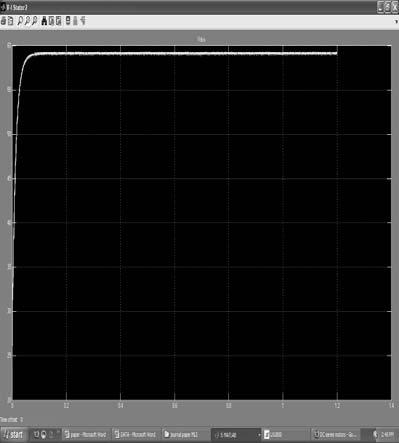
11 Simulation and Analysis of SVPWM Based 2-Level 179 Modeling of Second Level Inverter Circuit diagram Figure 4.2: Simulation of second level inverter.
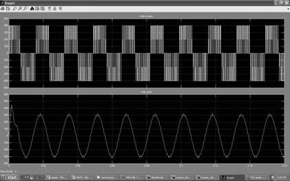
12 180 M. Lakshmi Swarupa, G. Tulasi Ram Das and P.V. Raj Gopal Second level THD VALUE FIG Output of second level inverter Modeling of Third Level Inverter Circuit diagram Figure 4.3: Simulation of third level inverter.
13 Simulation and Analysis of SVPWM Based 2-Level 181 Table No 4: Triggering pulse. 1 TO 8 = MOSFET SWITCHES, 1- TURN ON, 0 TURN OFF VOLTAGE LEVEL v/ V (v/2) (v/2) v (v/2) THD = Figure 4.3: Output of third level inverter.


14 182 M. Lakshmi Swarupa, G. Tulasi Ram Das and P.V. Raj Gopal
![Simulation and Analysis of SVPWM Based 2-Level 183 References [1] X. Li, R.](/docs-images/80/82176412/images/15-0.jpg "Duke and S. Round.")

![,Darwin, Australia, 1999, pp 247-251. [2] D. W. Novotny and T. A. Lipo.](/docs-images/80/82176412/images/15-2.jpg "Vector Control and Dynamics of AC Drives, Oxford University Press, 1997. [3] J.")
15 Simulation and Analysis of SVPWM Based 2-Level 183 References [1] X. Li, R. Duke and S. Round. Development of a threephasethree-level inverter for an electric vehicle. Australasian Universities Power Engineering Conf.,Darwin, Australia, 1999, pp [2] D. W. Novotny and T. A. Lipo. Vector Control and Dynamics of AC Drives, Oxford University Press, [3] J. Holtz. Pulse width Modulation for Electronic Power Conversion. Proc. of the IEEE, Vol. 82, No.8, pp , Aug 1994.
16 184 M. Lakshmi Swarupa, G. Tulasi Ram Das and P.V. Raj Gopal [4] I. Takahashi and T. Noguchi. A new quick response and high efficiency control strategy for an induction motor. IEEE Trans. Industry Applications. Vol. IA-22, No. 5, pp , Sept/Oct [5] T.G. Habetler, F. Profumo, M. Pastorelli, and L.M.Tolbert. Direct Torque Control of Induction Machines using Space Vector Modulation. IEEETrans. Industry Applications. Vol. 28, No. 5, Sept/Oct 1992 [6] J-K. Kang and S-K. Sul. New Direct Torque Control of Induction Motor for Minimum Torque Ripple and Constant Switching Frequency. IEEETrans. Industry Applications, Vol. 35, No. 5, Sept/Oct [7] T.A. Lipo and A. Consoli, Modeling and simulation of induction motors with saturable leakagereactances, IEEE Trans. Ind. Applications, vol. IA-20, pp ,jan./Feb [8] S.I.Moon and A.Keyhani, Estimation of inductionmachine parameters from standstill domain data, IEEE Trans.Ind. Applications, vol.30 pp Nov/Dec [9] Seung-Iii Moon,Ali Keyhani,Srinivas Pillutla, Nonlinear Neural Network Modeling of an InductionMachine, IEEE Trans. On Control systemstechnology, vol.7,no2, pp March1999. [10] The MATLAB compilers user s guide in Mathworks hand book Math works [11] Pawel z. Grabowski, Marian.P. Kazmierkowski,B.K.Bose and Frede Blaabjerg A simple DirectTorque Neuro-Fuzzy control of PWM inverter FedInduction Motor Drive. [12] G.J.Rogers and D.Shirmohammdi, Inductionmachine modeling for electromagnetic transientprogram, IEEE transactions. Energy conversion, vol,ec-2, pp , Dec [13] A.Keyhani and H.Tsai, IGSPICE simulation ofinduction machines with saturable inductances, IEEEtransactions. Energy conversion, vol,4, pp , Mar [14] Pierre Biden, Thierry Lebey, Member, IEEE, GerardMontrery, Clandice Nealsu and Jacques saint- Michel Transient voltage distribution in inverter fed motorwindings: Experimental study and Modeling. IEEEtransactions on Power Electronics, vol.16, No.1., Jan [15] Robert T. Novotnak, Member, IEEE, John Chiasson,Member, IEEE, and Marc Bodson, Senior Member,IEEE, High Performance Motion control of aninduction motor with Magnetic saturation. IEEEtransactions on Control systems Technology, vol.7, No.3., May [16] B.J.A. Krose and P.Patrick van der smagt, AnIntroduction to Neural Networks, The University ofamsterdam, The Netherlands, Sept
Control of Induction Motor Fed with Inverter Using Direct Torque Control - Space Vector Modulation Technique
 Control of Induction Motor Fed with Inverter Using Direct Torque Control - Space Vector Modulation Technique Vikas Goswami 1, Sulochana Wadhwani 2 1 Department Of Electrical Engineering, MITS Gwalior 2
CHAPTER 3 VOLTAGE SOURCE INVERTER (VSI)
") 37 CHAPTER 3 VOLTAGE SOURCE INVERTER (VSI) 3.1 INTRODUCTION This chapter presents speed and torque characteristics of induction motor fed by a new controller. The proposed controller is based on fuzzy
37 CHAPTER 3 VOLTAGE SOURCE INVERTER (VSI) 3.1 INTRODUCTION This chapter presents speed and torque characteristics of induction motor fed by a new controller. The proposed controller is based on fuzzy
A Sliding Mode Controller for a Three Phase Induction Motor
 A Sliding Mode Controller for a Three Phase Induction Motor Eman El-Gendy Demonstrator at Computers and systems engineering, Mansoura University, Egypt Sabry F. Saraya Assistant professor at Computers
SPEED CONTROL OF INDUCTION MOTOR WITHOUT SPEED SENSOR AT LOW SPEED OPERATIONS
 SPEED CONTROL OF INDUCTION MOTOR WITHOUT SPEED SENSOR AT LOW SPEED OPERATIONS Akshay Prasad Dubey and Saravana Kumar R. School of Electrical Engineering, VIT University, Vellore, Tamil Nadu, India E-Mail:
Simulation of Speed Control of Induction Motor with DTC Scheme Patel Divyaben Lalitbhai 1 Prof. C. A. Patel 2 Mr. B. R. Nanecha 3
 IJSRD - International Journal for Scientific Research & Development Vol. 3, Issue 09, 2015 ISSN (online): 2321-0613 Simulation of Speed Control of Induction Motor with DTC Scheme Patel Divyaben Lalitbhai
IN MANY industrial applications, ac machines are preferable
 IEEE TRANSACTIONS ON INDUSTRIAL ELECTRONICS, VOL. 46, NO. 1, FEBRUARY 1999 111 Automatic IM Parameter Measurement Under Sensorless Field-Oriented Control Yih-Neng Lin and Chern-Lin Chen, Member, IEEE Abstract
A DUAL FUZZY LOGIC CONTROL METHOD FOR DIRECT TORQUE CONTROL OF AN INDUCTION MOTOR
 International Journal of Science, Environment and Technology, Vol. 3, No 5, 2014, 1713 1720 ISSN 2278-3687 (O) A DUAL FUZZY LOGIC CONTROL METHOD FOR DIRECT TORQUE CONTROL OF AN INDUCTION MOTOR 1 P. Sweety
International Journal of Intellectual Advancements and Research in Engineering Computations
 www.ijiarec.com MAR-2015 International Journal of Intellectual Advancements and Research in Engineering Computations SPEED CONTROL OF BLDC MOTOR BY USING UNIVERSAL BRIDGE WITH ABSTRACT ISSN: 2348-2079
A Practical Primer On Motor Drives (Part 13): Motor Drive Control Architectures And Algorithms
: Motor Drive Control Architectures And Algorithms") ISSUE: February 2017 A Practical Primer On Motor Drives (Part 13): Motor Drive Control Architectures And Algorithms by Ken Johnson, Teledyne LeCroy, Chestnut Ridge, N.Y. Part 12 began the explanation of
ISSUE: February 2017 A Practical Primer On Motor Drives (Part 13): Motor Drive Control Architectures And Algorithms by Ken Johnson, Teledyne LeCroy, Chestnut Ridge, N.Y. Part 12 began the explanation of
SPEED CONTROL OF AN INDUCTION MOTOR USING FUZZY LOGIC AND PI CONTROLLER AND COMPARISON OF CONTROLLERS BASED ON SPEED
 SPEED CONTROL OF AN INDUCTION MOTOR USING FUZZY LOGIC AND PI CONTROLLER AND COMPARISON OF CONTROLLERS BASED ON SPEED Naveena G J 1, Murugesh Dodakundi 2, Anand Layadgundi 3 1, 2, 3 PG Scholar, Dept. of
CHAPTER 2 CURRENT SOURCE INVERTER FOR IM CONTROL
 9 CHAPTER 2 CURRENT SOURCE INVERTER FOR IM CONTROL 2.1 INTRODUCTION AC drives are mainly classified into direct and indirect converter drives. In direct converters (cycloconverters), the AC power is fed
Efficiency Optimization of Induction Motor Drives using PWM Technique
 Efficiency Optimization of Induction Motor Drives using PWM Technique 1 Mahantesh Gutti, 2 Manish G. Rathi, 3 Jagadish Patil M TECH Student, EEE Dept. Associate Professor, ECE Dept.M TECH Student, EEE
Matlab Simulation of Induction Motor Drive using V/f Control Method
 IJSRD - International Journal for Scientific Research & Development Vol. 5, Issue 01, 2017 ISSN (online): 2321-0613 Matlab Simulation of Induction Motor Drive using V/f Control Method Mitul Vekaria 1 Darshan
BECAUSE OF their low cost and high reliability, many
 824 IEEE TRANSACTIONS ON INDUSTRIAL ELECTRONICS, VOL. 45, NO. 5, OCTOBER 1998 Sensorless Field Orientation Control of Induction Machines Based on a Mutual MRAS Scheme Li Zhen, Member, IEEE, and Longya
Digital Control of Permanent Magnet Synchronous Motor
 Digital Control of Permanent Magnet Synchronous Motor Jayasri R. Nair 1 Assistant Professor, Dept. of EEE, Rajagiri School Of Engineering and Technology, Kochi, Kerala, India 1 ABSTRACT: The principle
Synchronous Current Control of Three phase Induction motor by CEMF compensation
 Synchronous Current Control of Three phase Induction motor by CEMF compensation 1 Kiran NAGULAPATI, 2 Dhanamjaya Appa Rao, 3 Anil Kumar VANAPALLI 1,2,3 Assistant Professor, ANITS, Sangivalasa, Visakhapatnam,
Reduction of Harmonics and Torque Ripples of BLDC Motor by Cascaded H-Bridge Multi Level Inverter Using Current and Speed Control Techniques
 Reduction of Harmonics and Torque Ripples of BLDC Motor by Cascaded H-Bridge Multi Level Inverter Using Current and Speed Control Techniques A. Sneha M.Tech. Student Scholar Department of Electrical &
Analysis of Voltage Source Inverters using Space Vector PWM for Induction Motor Drive
 IOSR Journal of Electrical and Electronics Engineering (IOSR-JEEE) ISSN: 2278-1676 Volume 2, Issue 6 (Sep-Oct. 2012), PP 14-19 Analysis of Voltage Source Inverters using Space Vector PWM for Induction
IMPLEMENTATION OF NEURAL NETWORK IN ENERGY SAVING OF INDUCTION MOTOR DRIVES WITH INDIRECT VECTOR CONTROL
 IMPLEMENTATION OF NEURAL NETWORK IN ENERGY SAVING OF INDUCTION MOTOR DRIVES WITH INDIRECT VECTOR CONTROL * A. K. Sharma, ** R. A. Gupta, and *** Laxmi Srivastava * Department of Electrical Engineering,
A Comparative Study between DPC and DPC-SVM Controllers Using dspace (DS1104)
") International Journal of Electrical and Computer Engineering (IJECE) Vol. 4, No. 3, June 2014, pp. 322 328 ISSN: 2088-8708 322 A Comparative Study between DPC and DPC-SVM Controllers Using dspace (DS1104)
International Journal of Electrical and Computer Engineering (IJECE) Vol. 4, No. 3, June 2014, pp. 322 328 ISSN: 2088-8708 322 A Comparative Study between DPC and DPC-SVM Controllers Using dspace (DS1104)
VECTOR CONTROL SCHEME FOR INDUCTION MOTOR WITH DIFFERENT CONTROLLERS FOR NEGLECTING THE END EFFECTS IN HEV APPLICATIONS
 VECTOR CONTROL SCHEME FOR INDUCTION MOTOR WITH DIFFERENT CONTROLLERS FOR NEGLECTING THE END EFFECTS IN HEV APPLICATIONS M.LAKSHMISWARUPA 1, G.TULASIRAMDAS 2 & P.V.RAJGOPAL 3 1 Malla Reddy Engineering College,
HIGH PERFORMANCE CONTROL OF AC DRIVES WITH MATLAB/SIMULINK MODELS
 HIGH PERFORMANCE CONTROL OF AC DRIVES WITH MATLAB/SIMULINK MODELS Haitham Abu-Rub Texas A&M University at Qatar, Qatar Atif Iqbal Qatar University, Qatar and Aligarh Muslim University, India Jaroslaw Guzinski
ADVANCED DC-DC CONVERTER CONTROLLED SPEED REGULATION OF INDUCTION MOTOR USING PI CONTROLLER
 Asian Journal of Electrical Sciences (AJES) Vol.2.No.1 2014 pp 16-21. available at: www.goniv.com Paper Received :08-03-2014 Paper Accepted:22-03-2013 Paper Reviewed by: 1. R. Venkatakrishnan 2. R. Marimuthu
IEEE TRANSACTIONS ON POWER ELECTRONICS, VOL. 14, NO. 3, MAY A Sliding Mode Current Control Scheme for PWM Brushless DC Motor Drives
 IEEE TRANSACTIONS ON POWER ELECTRONICS, VOL. 14, NO. 3, MAY 1999 541 A Sliding Mode Current Control Scheme for PWM Brushless DC Motor Drives Jessen Chen and Pei-Chong Tang Abstract This paper proposes
A New Variable Gain PI Controller Used For Direct Torque Neuro Fuzzy Speed Control Of Induction Machine Drive
 A New Variable Gain PI Controller Used For Direct Torque Neuro Fuzzy Speed Control Of Induction Machine Drive A. Miloudi 1, E. A. Al-Radadi 2, Y. Miloud 1, A. Draou 2, 1 University Centre of Saïda, BP
Improved direct torque control of induction motor with dither injection
 Sādhanā Vol. 33, Part 5, October 2008, pp. 551 564. Printed in India Improved direct torque control of induction motor with dither injection R K BEHERA andspdas Department of Electrical Engineering, Indian
CHAPTER 4 CONTROL ALGORITHM FOR PROPOSED H-BRIDGE MULTILEVEL INVERTER
 65 CHAPTER 4 CONTROL ALGORITHM FOR PROPOSED H-BRIDGE MULTILEVEL INVERTER 4.1 INTRODUCTION Many control strategies are available for the control of IMs. The Direct Torque Control (DTC) is one of the most
Induction Motor Drive using SPWM Fed Five Level NPC Inverter for Electric Vehicle Application
 IJIRST International Journal for Innovative Research in Science & Technology Volume 4 Issue 7 November 2017 ISSN (online): 2349-6010 Induction Motor Drive using SPWM Fed Five Level NPC Inverter for Electric
Vol. 1, Issue VI, July 2013 ISSN
 ANALYSIS - FOR DIFFERENT LEVELS OF CASCADE MULTI-LEVEL STATCOM FOR DTC INDUCTION MOTOR DRIVE GaneswaraRao Ippili 1, Swarupa.V 2, Pavan Kumar Maddukuri 3 1,2,3 Assistant Professor, Dept. of Electrical and
OPTIMAL TORQUE RIPPLE CONTROL OF ASYNCHRONOUS DRIVE USING INTELLIGENT CONTROLLERS
 OPTIMAL TORQUE RIPPLE CONTROL OF ASYNCHRONOUS DRIE USING INTELLIGENT CONTROLLERS J.N.Chandra Sekhar 1 and Dr.G. Marutheswar 2 1 Department of EEE, Assistant Professor, S University College of Engineering,
Keywords - Induction motor, space vector PWM, DTC, sensorless control, reconstruction.
 e-issn: 2278-1676, p-issn: 232-3331 Reconstruction of Phase Current of Induction Motor Drive based on DC Link Measurement Najma Ansari, Nahid Khan, Shital B. Rewatkar Department of Electrical Engineering,
Control of Electric Machine Drive Systems
 Control of Electric Machine Drive Systems Seung-Ki Sul IEEE 1 PRESS к SERIES I 0N POWER ENGINEERING Mohamed E. El-Hawary, Series Editor IEEE PRESS WILEY A JOHN WILEY & SONS, INC., PUBLICATION Contents
ON-LINE NONLINEARITY COMPENSATION TECHNIQUE FOR PWM INVERTER DRIVES
 INTERNATIONAL JOURNAL OF ELECTRICAL ENGINEERING & TECHNOLOGY (IJEET) Proceedings of the International Conference on Emerging Trends in Engineering and Management (ICETEM14) ISSN 0976 6545(Print) ISSN 0976
DIRECT TORQUE CONTROL OF THREE PHASE INDUCTION MOTOR BY USING FOUR SWITCH INVERTER
 DIRECT TORQUE CONTROL OF THREE PHASE INDUCTION MOTOR BY USING FOUR SWITCH INVERTER Mr. Aniket C. Daiv. TSSM's BSCOER, Narhe ABSTRACT Induction motor proved its importance, since its invention and has been
DESIGN ANALYSIS AND IMPLEMENTATION OF SPACE VECTOR PULSE WIDTH MODULATING INVERTER USING DSP CONTROLLER FOR VECTOR CONTROLLED DRIVES
 INTERNATIONAL JOURNAL OF ELECTRICAL ENGINEERING & TECHNOLOGY (IJEET) International Journal of Electrical Engineering and Technology (IJEET), ISSN 0976 6545(Print), ISSN 0976 6545(Print) ISSN 0976 6553(Online)
Simulation Analysis of Three Phase & Line to Ground Fault of Induction Motor Using FFT
 www.ijird.com June, 4 Vol 3 Issue 6 ISSN 78 (Online) Simulation Analysis of Three Phase & Line to Ground Fault of Induction Motor Using FFT Anant G. Kulkarni Research scholar, Dr. C. V. Raman University,
New Direct Torque Control of DFIG under Balanced and Unbalanced Grid Voltage
 1 New Direct Torque Control of DFIG under Balanced and Unbalanced Grid Voltage B. B. Pimple, V. Y. Vekhande and B. G. Fernandes Department of Electrical Engineering, Indian Institute of Technology Bombay,
International Journal of Advance Engineering and Research Development
 Scientific Journal of Impact Factor (SJIF): 4.72 International Journal of Advance Engineering and Research Development Volume 4, Issue 4, April -217 e-issn (O): 2348-447 p-issn (P): 2348-646 Analysis,
International Journal of Scientific & Engineering Research, Volume 5, Issue 6, June-2014 ISSN
 35 Torque Ripple Reduction in Three-level SVM Based Direct Torque Control of Induction Motor Kousalya D Asiya Husna V Manoj Kumar N Department of EEE Department of EEE Department of EEE RMK Engineering
Simulation and Dynamic Response of Closed Loop Speed Control of PMSM Drive Using Fuzzy Controller
 Simulation and Dynamic Response of Closed Loop Speed Control of PMSM Drive Using Fuzzy Controller Anguru Sraveen Babu M.Tech Student Scholar Dept of Electrical & Electronics Engineering, Baba Institute
Sensorless Speed Control Scheme for Induction Motor Drive Using DC link Measurements
 Sensorless Speed Control Scheme for Induction Motor Drive Using DC link Measurements Yesupadam C 1, Sk Gouse Basha 2, Ravi Kumar Reddy P 3 1*Pursuing M.Tech in the field of Power & Industrial Drives 2*Working
Simulation and Dynamic Response of Closed Loop Speed Control of PMSM Drive Using Fuzzy Controller
 Simulation and Dynamic Response of Closed Loop Speed Control of PMSM Drive Using Fuzzy Controller Anguru Sraveen Babu M.Tech Student Scholar Department of Electrical & Electronics Engineering, Baba Institute
Compensation for Inverter Nonlinearity Using Trapezoidal Voltage
 International OPEN ACCESS Journal Of Modern Engineering Research (IJMER) Compensation for Inverter Nonlinearity Using Trapezoidal Voltage Maria Joseph M 1, Siby C Arjun 2 1,2 Electrical and Electronics
International Journal of Digital Application & Contemporary research Website: (Volume 2, Issue 8, March 2014)
") Field Oriented Control of PMSM Using Improved Space Vector Modulation Technique Yeshwant Joshi Kapil Parikh Dr. Vinod Kumar Yadav yshwntjoshi@gmail.com kapilparikh@ymail.com vinodcte@yahoo.co.in Abstract:
Field Oriented Control of PMSM Using Improved Space Vector Modulation Technique Yeshwant Joshi Kapil Parikh Dr. Vinod Kumar Yadav yshwntjoshi@gmail.com kapilparikh@ymail.com vinodcte@yahoo.co.in Abstract:
FUZZY LOGIC BASED DIRECT TORQUE CONTROL OF THREE PHASE INDUCTION MOTOR
 Volume 116 No. 11 2017, 171-179 ISSN: 1311-8080 (printed version); ISSN: 1314-3395 (on-line version) url: http://www.ijpam.eu doi: 10.12732/ijpam.v116i11.18 ijpam.eu FUZZY LOGIC BASED DIRECT TORQUE CONTROL
Induction Motor Drives Fed By Four- Leg Inverter
 Induction Motor Drives Fed By Four- Leg Inverter 1 K.Gopi 1, P.Varunkrishna 2 M.Tech student, EEE, Arjun College of Tech &Science, R.R.Dist, Telangana, India 2 Assistant Professor, EEE, Arjun College of
Selected Problems of Induction Motor Drives with Voltage Inverter and Inverter Output Filters
 9 Selected Problems of Induction Motor Drives with Voltage Inverter and Inverter Output Filters Drives and Filters Overview. Fast switching of power devices in an inverter causes high dv/dt at the rising
SCOTT TRANSFORMER AND DIODE CLAMPED INVERTER FED INDUCTION MOTOR BASED ON FOC
 RESEARCH ARTICLE OPEN ACCESS SCOTT TRANSFORMER AND DIODE CLAMPED INVERTER FED INDUCTION MOTOR BASED ON FOC 1, Ms. Snehal M. Khobragade, 2, Prof.B.S.Dani Mtech(IDC) pursuing Priyadarshini college of Engineering
SPEED CONTROL OF SENSORLESS BLDC MOTOR WITH FIELD ORIENTED CONTROL
 ISSN: 2349-2503 SPEED CONTROL OF SENSORLESS BLDC MOTOR WITH FIELD ORIENTED CONTROL JMuthupandi 1 DCitharthan 2 MVaratharaj 3 1 (UG Scholar/EEE department/ Christ the king engg college/ Coimbatore/India/
Self-Tuning PI-Type Fuzzy Direct Torque Control for Three-phase Induction Motor
 Self-Tuning PI-Type Fuzzy Direct Torque Control for Three-phase Induction Motor JOSÉ L. AZCUE P., ALFEU J. SGUAREZI FILHO and ERNESTO RUPPERT Department of Energy Control and Systems University of Campinas
SPEED CONTROL OF PERMANENT MAGNET SYNCHRONOUS MOTOR USING VOLTAGE SOURCE INVERTER
 SPEED CONTROL OF PERMANENT MAGNET SYNCHRONOUS MOTOR USING VOLTAGE SOURCE INVERTER Kushal Rajak 1, Rajendra Murmu 2 1,2 Department of Electrical Engineering, B I T Sindri, (India) ABSTRACT This paper presents
CHAPTER-5 DESIGN OF DIRECT TORQUE CONTROLLED INDUCTION MOTOR DRIVE
 113 CHAPTER-5 DESIGN OF DIRECT TORQUE CONTROLLED INDUCTION MOTOR DRIVE 5.1 INTRODUCTION This chapter describes hardware design and implementation of direct torque controlled induction motor drive with
Index Terms: Vector control scheme, indirect vector control scheme, Scalar control, Marine propulsion I. INTRODUCTION
 American International Journal of Research in Science, Technology, Engineering & Mathematics Available online at http://www.iasir.net ISSN (Print): 2328-3491, ISSN (Online): 2328-3580, ISSN (CD-ROM): 2328-3629
MATLAB/SIMULINK MODEL OF FIELD ORIENTED CONTROL OF PMSM DRIVE USING SPACE VECTORS
 MATLAB/SIMULINK MODEL OF FIELD ORIENTED CONTROL OF PMSM DRIVE USING SPACE VECTORS Remitha K Madhu 1 and Anna Mathew 2 1 Department of EE Engineering, Rajagiri Institute of Science and Technology, Kochi,
CURRENT FOLLOWER APPROACH BASED PI AND FUZZY LOGIC CONTROLLERS FOR BLDC MOTOR DRIVE SYSTEM FED FROM CUK CONVERTER
 CURRENT FOLLOWER APPROACH BASED PI AND FUZZY LOGIC CONTROLLERS FOR BLDC MOTOR DRIVE SYSTEM FED FROM CUK CONVERTER N. Mohanraj and R. Sankaran Shanmugha Arts, Science, Technology and Research Academy University,
ROTOR FLUX VECTOR CONTROL TRACKING FOR SENSORLESS INDUCTION MOTOR
 International Journal of Scientific & Engineering Research, Volume 7, Issue 4, April-2016 668 ROTOR FLUX VECTOR CONTROL TRACKING FOR SENSORLESS INDUCTION MOTOR Fathima Farook 1, Reeba Sara Koshy 2 Abstract
A Novel Four Switch Three Phase Inverter Controlled by Different Modulation Techniques A Comparison
 Volume 2, Issue 1, January-March, 2014, pp. 14-23, IASTER 2014 www.iaster.com, Online: 2347-5439, Print: 2348-0025 ABSTRACT A Novel Four Switch Three Phase Inverter Controlled by Different Modulation Techniques
ANALYSIS OF EFFECTS OF VECTOR CONTROL ON TOTAL CURRENT HARMONIC DISTORTION OF ADJUSTABLE SPEED AC DRIVE
 ANALYSIS OF EFFECTS OF VECTOR CONTROL ON TOTAL CURRENT HARMONIC DISTORTION OF ADJUSTABLE SPEED AC DRIVE KARTIK TAMVADA Department of E.E.E, V.S.Lakshmi Engineering College for Women, Kakinada, Andhra Pradesh,
Three Phase Induction Motor Drive Using Single Phase Inverter and Constant V/F method
 Three Phase Induction Motor Drive Using Single Phase Inverter and Constant V/F method Nitin Goel 1, Shashi yadav 2, Shilpa 3 Assistant Professor, Dept. of EE, YMCA University of Science & Technology, Faridabad,
Analysis & Hardware Implementation Of Three-Phase Voltage Source Inverter
 Analysis & Hardware Implementation Of Three-Phase Voltage Source Inverter Prachi S. Dharmadhikari M-Tech Student: Electrical Engg.Department R.C.O.E.M, Nagpur (India) Gaurav N. Goyal Asst. Prof : Electrical
Speed control of sensorless BLDC motor with two side chopping PWM
 IOSR Journal of Electrical and Electronics Engineering (IOSR-JEEE) e-issn: 2278-1676,p-ISSN: 2320-3331, Volume 6, Issue 3 (May. - Jun. 2013), PP 16-20 Speed control of sensorless BLDC motor with two side
CHAPTER-III MODELING AND IMPLEMENTATION OF PMBLDC MOTOR DRIVE
 CHAPTER-III MODELING AND IMPLEMENTATION OF PMBLDC MOTOR DRIVE 3.1 GENERAL The PMBLDC motors used in low power applications (up to 5kW) are fed from a single-phase AC source through a diode bridge rectifier
Comparison between Scalar & Vector Control Technique for Induction Motor Drive
 Comparison between Scalar & Vector Control Technique for Induction Motor Drive Mr. Ankit Agrawal 1, Mr. Rakesh Singh Lodhi 2, Dr. Pragya Nema 3 1PG Research Scholar, Oriental University, Indore (M.P),
ANALYSIS OF POWER QUALITY IMPROVEMENT OF BLDC MOTOR DRIVE USING CUK CONVERTER OPERATING IN DISCONTINUOUS CONDUCTION MODE
 ANALYSIS OF POWER QUALITY IMPROVEMENT OF BLDC MOTOR DRIVE USING CUK CONVERTER OPERATING IN DISCONTINUOUS CONDUCTION MODE Bhushan P. Mokal 1, Dr. K. Vadirajacharya 2 1,2 Department of Electrical Engineering,Dr.
Simulation of Sensorless Digital Control of BLDC Motor Based on Zero Cross Detection
 Simulation of Sensorless Digital Control of BLDC Motor Based on Zero Cross Detection S.P. Ajitha 1, S. Bagavathy 2, Dr. P. Maruthu Pandi 3 1 PG Scholar, Department of Power Electronics and Drives, Sri
Analysis, Design, and Comparison of VSI Fed Scalar & Vector Control 3-
 Analysis, Design, and Comparison of VSI Fed Scalar & Vector Control 3- Garima Solanki Electrical & Electronics Engineering Department, JIT, Borawan, Khargone(M.P.) Chandan Gurjar Electrical & Electronics
DC Link approach to Variable-Speed, Sensorless, Induction Motor Drive
 National Conference On Advances in Energy and Power Control Engineering (AEPCE-2K2) DC Link approach to Variable-Speed, Sensorless, Induction Motor Drive Ch.U.Phanendra.Kumar SK.Mohiddin 2 A.Hanumaiah
Chhattisgarh Swami Vivekanand Technical University, Bhilai
 Scheme of teaching and examination M.E.(POWER ELECTRONICS) in the Department of Electrical Engg. IIIrd SEMESTER S N Board of study Subject code 1 Electrical Engg. 562311(24) Subject Name Static VAR Controller
A Performance Study of PI controller and Fuzzy logic controller in V/f Control of Three Phase Induction Motor Using Space Vector Modulation
 A Performance Study of PI controller and Fuzzy logic controller in V/f Control of Three Phase Induction Motor Using Space Vector Modulation Safdar Fasal T K & Unnikrishnan L Department of Electrical and
Sensorless control of BLDC motor based on Hysteresis comparator with PI control for speed regulation
 Sensorless control of BLDC motor based on Hysteresis comparator with PI control for speed regulation Thirumoni.T 1,Femi.R 2 PG Student 1, Assistant Professor 2, Department of Electrical and Electronics
Fuzzy Logic Controller Based Direct Torque Control of PMBLDC Motor
 Fuzzy Logic Controller Based Direct Torque Control of PMBLDC Motor Madasamy P 1, Ramadas K 2, Nagapriya S 3 1, 2, 3 Department of Electrical and Electronics Engineering, Alagappa Chettiar College of Engineering
CHAPTER 4 FUZZY BASED DYNAMIC PWM CONTROL
 47 CHAPTER 4 FUZZY BASED DYNAMIC PWM CONTROL 4.1 INTRODUCTION Passive filters are used to minimize the harmonic components present in the stator voltage and current of the BLDC motor. Based on the design,
Simulation & Implementation Of Three Phase Induction Motor On Single Phase By Using PWM Techniques
 Simulation & Implementation Of Three Phase Induction Motor On Single Phase By Using PWM Techniques Ashwini Kadam 1,A.N.Shaikh 2 1 Student, Department of Electronics Engineering, BAMUniversity,akadam572@gmail.com,9960158714
ADVANCED ROTOR POSITION DETECTION TECHNIQUE FOR SENSORLESS BLDC MOTOR CONTROL
 International Journal of Soft Computing and Engineering (IJSCE) ISSN: 3137, Volume, Issue-1, March 1 ADVANCED ROTOR POSITION DETECTION TECHNIQUE FOR SENSORLESS BLDC MOTOR CONTROL S.JOSHUWA, E.SATHISHKUMAR,
A COMPARISON STUDY OF THE COMMUTATION METHODS FOR THE THREE-PHASE PERMANENT MAGNET BRUSHLESS DC MOTOR
 A COMPARISON STUDY OF THE COMMUTATION METHODS FOR THE THREE-PHASE PERMANENT MAGNET BRUSHLESS DC MOTOR Shiyoung Lee, Ph.D. Pennsylvania State University Berks Campus Room 120 Luerssen Building, Tulpehocken
Development of Variable Speed Drive for Single Phase Induction Motor Based on Frequency Control
 Development of Variable Speed Drive for Single Phase Induction Motor Based on Frequency Control W.I.Ibrahim, R.M.T.Raja Ismail,M.R.Ghazali Faculty of Electrical & Electronics Engineering Universiti Malaysia
Modeling & Simulation of PMSM Drives with Fuzzy Logic Controller
 Vol. 3, Issue. 4, Jul - Aug. 2013 pp-2492-2497 ISSN: 2249-6645 Modeling & Simulation of PMSM Drives with Fuzzy Logic Controller Praveen Kumar 1, Anurag Singh Tomer 2 1 (ME Scholar, Department of Electrical
Modeling and Simulation Analysis of Eleven Phase Brushless DC Motor
 Modeling and Simulation Analysis of Eleven Phase Brushless DC Motor Priyanka C P 1,Sija Gopinathan 2, Anish Gopinath 3 M. Tech Student, Department of EEE, Mar Athanasius College of Engineering, Kothamangalam,
Australian Journal of Basic and Applied Sciences. Simulation and Analysis of Closed loop Control of Multilevel Inverter fed AC Drives
 AENSI Journals Australian Journal of Basic and Applied Sciences ISSN:1991-8178 Journal home page: www.ajbasweb.com Simulation and Analysis of Closed loop Control of Multilevel Inverter fed AC Drives 1
SVM-DTC OF AN INDUCTION MOTOR BASED ON VOLTAGE AND STATOR FLUX ANGLE USING FUZZY LOGIC CONTROLLER
 SVM-DTC OF AN INDUCTION MOTOR BASED ON VOLTAGE AND STATOR FLUX ANGLE USING FUZZY LOGIC CONTROLLER T.Sravani 1, S.Sridhar 2 1PG Student(Power & Industrial Drives), Department of EEE, JNTU Anantapuramu,
ANALYSIS OF V/f CONTROL OF INDUCTION MOTOR USING CONVENTIONAL CONTROLLERS AND FUZZY LOGIC CONTROLLER
 ANALYSIS OF V/f CONTROL OF INDUCTION MOTOR USING CONVENTIONAL CONTROLLERS AND FUZZY LOGIC CONTROLLER Archana G C 1 and Reema N 2 1 PG Student [Electrical Machines], Department of EEE, Sree Buddha College
Analysis and Comparison of DTC Technique in 2 Levels & 3 Level Inverter Fed Induction Motor Drive
 Analysis and Comparison of DTC Technique in 2 Levels & 3 Level Inverter Fed Induction Motor Drive Champa Chauhan Electrical engineering MEFGI Abstract- Two level inverter fed technique has dynamic performances
Inductance Based Sensorless Control of Switched Reluctance Motor
 I J C T A, 9(16), 2016, pp. 8135-8142 International Science Press Inductance Based Sensorless Control of Switched Reluctance Motor Pradeep Vishnuram*, Siva T.**, Sridhar R.* and Narayanamoorthi R.* ABSTRACT
Performance Enhancement of Sensorless Control of Z-Source Inverter Fed BLDC Motor
 IJSTE - International Journal of Science Technology & Engineering Volume 1 Issue 11 May 2015 ISSN (online): 2349-784X Performance Enhancement of Sensorless Control of Z-Source Inverter Fed BLDC Motor K.
CHAPTER 2 VSI FED INDUCTION MOTOR DRIVE
 CHAPTER 2 VI FE INUCTION MOTOR RIVE 2.1 INTROUCTION C motors have been used during the last century in industries for variable speed applications, because its flux and torque can be controlled easily by
An Induction Motor Control by Space Vector PWM Technique
 An Induction Motor Control by Space Vector PWM Technique Sanket Virani PG student Department of Electrical Engineering, Sarvajanik College of Engineering & Technology, Surat, India Abstract - This paper
Decoupled Space Vector PWM for Dual inverter fed Open End winding Induction motor drive
 International Journal of Scientific & Engineering Research, Volume 3, Issue 10, October-2012 Decoupled Space Vector PWM for Dual inverter fed Open End winding Induction motor drive N.Rosaiah, Chalasani.Hari
PERFORMANCE ANALYSIS OF SVPWM AND FUZZY CONTROLLED HYBRID ACTIVE POWER FILTER
 International Journal of Electrical and Electronics Engineering Research (IJEEER) ISSN 2250-155X Vol. 3, Issue 2, Jun 2013, 309-318 TJPRC Pvt. Ltd. PERFORMANCE ANALYSIS OF SVPWM AND FUZZY CONTROLLED HYBRID
Analysis of Indirect Temperature-Rise Tests of Induction Machines Using Time Stepping Finite Element Method
 IEEE TRANSACTIONS ON ENERGY CONVERSION, VOL. 16, NO. 1, MARCH 2001 55 Analysis of Indirect Temperature-Rise Tests of Induction Machines Using Time Stepping Finite Element Method S. L. Ho and W. N. Fu Abstract
Design and implementation of Open & Close Loop Speed control of Three Phase Induction Motor Using PI Controller
 Design and implementation of Open & Close Loop Speed control of Three Phase Induction Motor Using PI Controller Ibtisam Naveed 1, Adnan Sabir 2 1 (Electrical Engineering, NFC institute of Engineering and
Sharmila Kumari.M, Sumathi.V, Vivekanandan S, Shobana S
 International Journal of Scientific & Engineering Research, Volume 5, Issue 4, April-2014 388 PERFORMANCE IMPROVEMENT OF BLDC MOTOR USING FUZZY LOGIC CONTROLLER Sharmila Kumari.M, Sumathi.V, Vivekanandan
Generalized PWM algorithm for Direct Torque Controlled Induction Motor Drives using the only Sampled Voltages
 Generalized PWM algorithm for Direct Torque Controlled Induction Motor Drives using the only Sampled Voltages J.Bhavani 1, J.Amarnath 2, D.Subbarayudu 3 1Associate professor, EEE Department, Malla Reddy
Speed Control of Induction Motor using Predictive Current Control and SVPWM
 Speed Control of Induction Motor using Predictive Current Control and SVPWM S. SURIYA, P. BALAMURUGAN M.E Student, Power Electronics and Drives Department, Easwari Engineering College, Chennai, Tamil Nadu,
Simple speed sensorless DTC-SVM scheme for induction motor drives
 BULLETIN OF THE POLISH ACADEMY OF SCIENCES TECHNICAL SCIENCES, Vol. 61, No. 2, 2013 DOI: 10.2478/bpasts-2013-0028 Simple speed sensorless DTC-SVM scheme for induction motor drives H. ABU-RUB 1, D. STANDO
Research Article International Journals of Advanced Research in Computer Science and Software Engineering ISSN: X (Volume-7, Issue-6)
") International Journals of Advanced Research in Computer Science and Software Engineering Research Article June 2017 Closed Loop PI Control of a Single Phase Induction Motor Using SPWM Kuheli Ghosh Goswami
International Journals of Advanced Research in Computer Science and Software Engineering Research Article June 2017 Closed Loop PI Control of a Single Phase Induction Motor Using SPWM Kuheli Ghosh Goswami
II. PROPOSED CLOSED LOOP SPEED CONTROL OF PMSM BLOCK DIAGRAM
 Closed Loop Speed Control of Permanent Magnet Synchronous Motor fed by SVPWM Inverter Malti Garje 1, D.R.Patil 2 1,2 Electrical Engineering Department, WCE Sangli Abstract This paper presents very basic
The Amalgamation Performance Analysis of the LCI and VSI Fed Induction Motor Drive
 International Journal of Engineering and Technical Research (IJETR) ISSN: 2321-0869 (O) 2454-4698 (P), Volume-7, Issue-5, May 2017 The Amalgamation Performance Analysis of the LCI and VSI Fed Induction
Enhanced Performance of Multilevel Inverter Fed Induction Motor Drive
 Enhanced Performance of Multilevel Inverter Fed Induction Motor Drive Venkata Anil Babu Polisetty 1, B.R.Narendra 2 PG Student [PE], Dept. of EEE, DVR. & Dr.H.S.MIC College of Technology, AP, India 1 Associate
A Dynamic Modeling Permanent Magnet Synchronous Motor Drive System
 A Dynamic Modeling Permanent Magnet Synchronous Motor Drive System MISS. KINJAL G. PATEL P.G. Student, Department of Electrical Engineering SSSRGI, Vadasma, Mehsana MR. CHIRAG V. PATEL Assistant Professor,
Reduction Of Harmonics & Torque Ripples Of Bldc Motor By Cascaded H-Bridge Multi Level Inveter Using Current & Speed Control Techniques
 Reduction Of Harmonics & Torque Ripples Of Bldc Motor By Cascaded H-Bridge Multi Level Inveter Using Current & Speed Control Techniques Anugu Sneha, Dr. R. Somanatham Abstract Considering the drive advantages