Radar Systems Engineering Lecture 10 Part 1 Radar Clutter
|
|
|
- Margaret Higgins
- 6 years ago
- Views:
Transcription
1 Radar Systems Engineering Lecture 10 Part 1 Radar Clutter Dr. Robert M. O Donnell Guest Lecturer Radar Systems Course 1
 User Displays and Radar Control General Purpose Computer Tracking Parameter Estimation Thresholding Detection Data")
2 Block Diagram of Radar System Target Radar Cross Section Propagation Medium T / R Switch Power Amplifier Transmitter Waveform Generation Antenna Buildings (Radar Clutter) Signal Processor Computer Receiver A / D Converter Pulse Compression Clutter Rejection (Doppler Filtering) User Displays and Radar Control General Purpose Computer Tracking Parameter Estimation Thresholding Detection Data Recording Photo Image Courtesy of US Air Force Used with permission. Radar Systems Course 2
3 Outline Motivation Backscatter from unwanted objects Ground Sea Rain Birds and Insects Radar Systems Course 3

4 Why Study Radar Clutter? Naval Air Defense Scenario Bird Flock Rain Chaff Targets Target Sea Ground Urban Buildings Ground Hills Courtesy MIT Lincoln Laboratory Used with permission Radar Systems Course 4


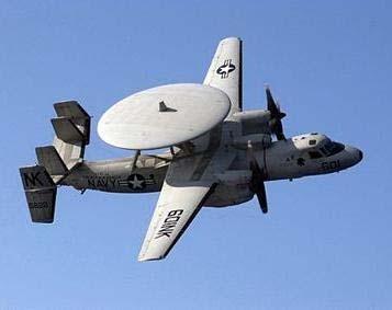
5 Radars for Which Clutter is a Issue AEGIS SPY 1 Courtesy of ITT Gillfillan Used with permission SPS-48 SPS-49 Courtesy of US Navy Courtesy of US Navy AWACS E-3A OTH Radar Courtesy of Raytheon Used with permission Courtesy of US Navy HAWKEYE E-2C Courtesy of US Air Force Radar Systems Course 5

")


6 Radars for Which Clutter is a Issue Courtesy of US Air Force JOINT STARS E-8 AEROSTAT RADAR APG-63 V(2) F-16 APG-68 Courtesy of Alphapapa Courtesy of Boeing Used with permission Courtesy of Northrop Grumman Used with permission FAA ARSR-4 TPS-79 WEDGETAIL Courtesy of Lockheed Martin Used with permission Courtesy of Wings777 Radar Systems Course 6
7 How to Handle Noise and Clutter Radar Systems Course 7

8 How to Handle Noise and Clutter If he doesn t take his arm off my shoulder I m going to hide his stash of Hershey Bars!! Why does Steve always talk me into doing ridiculous stunts like this? Radar Systems Course 8
 60 nautical miles 1.4 mw 875 W (700 1200 Hz) 1040 Hz average 12.8 rpm 4.8 m 2.")
9 Typical Air Surveillance Radar (Used for Sample Calculations) Radar Parameters Frequency FAA - Airport Surveillance Radar Instrumented range Peak power Average power Pulse repetition frequency Antenna rotation rate Antenna size S-band ( MHz) 60 nautical miles 1.4 mw 875 W ( Hz) 1040 Hz average 12.8 rpm 4.8 m 2.7 m Courtesy of MIT Lincoln Laboratory Used with permission Antenna gain 33 db Radar Systems Course 9
10 Outline Motivation Backscatter from unwanted objects Ground Sea Rain Birds and Insects Radar Systems Course 10
11 Outline - Ground Clutter Introduction Mean backscatter Frequency Terrain type Polarization Temporal statistics Doppler spectra Radar Systems Course 11
12 Attributes of Ground Clutter Mean value of backscatter from ground clutter Very large size relative to aircraft Varies statistically Frequency, spatial resolution, geometry, terrain type Doppler characteristics of ground clutter return Innate Doppler spread small (few knots) Mechanical scanning antennas add spread to clutter Relative motion of radar platform affects Doppler of ground clutter Ship Aircraft Radar Systems Course 12
 Display Map-like Display Radial distance to center Angle of radius vector Threshold crossings Range Azimuth Detections 0 db Shrader, W.")
13 Ground Based Radar Displays Mountainous Region of Lakehead, Ontario, Canada PPI Set for 30 nmi. Plan Position Indicator (PPI) Display Map-like Display Radial distance to center Angle of radius vector Threshold crossings Range Azimuth Detections 0 db Shrader, W. from Tutorial on MTI Radar presented at Selenia, Rome, Italy. Used with permission. Radar Systems Course 13

14 Photographs of Ground Based Radar s PPI (Different Levels of Attenuation) Mountainous Region of Lakehead, Ontario, Canada PPI Set for 30 nmi. Attenuation Level 0 db Attenuation Level 60 db Shrader, W. from Tutorial on MTI Radar presented at Selenia, Rome, Italy. Used with permission. Radar Systems Course 14


15 Photographs of Ground Based Radar s PPI 0 db Different Levels of Attenuation 10 db 40 db 50 db 0 db 20 db 30 db Shrader, W. from Tutorial on MTI Radar presented at Selenia, Rome, Italy. Used with permission. Radar Systems Course db 70 db
16 Geometry of Radar Clutter Radar Elevation View h ct / 2 φ ½ ct sec φ Plan View Radar θ B Clutter Rθ B σ = 0 σ A A = Rθ B [½ ct sec φ] Courtesy of MIT Lincoln Laboratory Used with permission Radar Systems Course 16
17 Calculation of Ground Clutter Typical Value of σ o = -20 db = c T σ Clutter = σ o A= σ o R θ B 2 For ASR-9 (Airport Surveillance Radar) c T R = 60 km 2 = 100m θ B = 1.5o = radians 0.01 m σ 2 Clutter = x 100 m x 60,000 m x radians = 1500 m 2 m 2 For σ Target = 1 m m 2 m 2 INPUT σ Target = σ Clutter OUTPUT σ Target = 20 σ Clutter Small single-engine aircraft Must suppress clutter by a factor of 1500 x 20 = 30,000 = 45 db For good detection Radar Systems Course 17 Courtesy of MIT Lincoln Laboratory Used with permission


18 Joint U.S./Canada Measurement Program Phase One radar VHF, UHF, L-, S-, X-bands Measurements conducted Archival data at Lincoln Laboratory Radar Systems Course sites Data shared with Canada and the United Kingdom Courtesy of MIT Lincoln Laboratory Used with permission
 El (deg) 13 42 5 15 3 10 1 4 1 4 Peak Power (kw) 10 10 10 10 10 Polarization HH,VV HH,VV HH,VV HH,VV HH,VV PRF (Hz) 500 500 500 500 500 Pulse Width (µs) 0.1, 0.")
19 Joint U.S./Canada Measurement Program Phase One Radar Radar System Parameters Frequency Band MHz) VHF UHF L-Band S-Band X-Band Antenna Gain (db) Antenna Beamwidth Az (deg) El (deg) Peak Power (kw) Polarization HH,VV HH,VV HH,VV HH,VV HH,VV PRF (Hz) Pulse Width (µs) 0.1, 0.25, and 1 0.1, 0.25, and 1 0.1, 0.25, and 1 0.1, 0.25, and 1 0.1, 0.25, and 1 Waveform A/D Converter Number of Bits Sampling Rate (MHz) Uncoded CW Pulse 13 10, 5, 1 Uncoded CW Pulse 13 10, 5, 1 Uncoded CW Pulse 13 10, 5, 1 Uncoded CW Pulse 13 10, 5, 1 Uncoded CW Pulse 13 10, 5, 1 Courtesy of MIT Lincoln Laboratory Adapted from Billingsley, Reference 2 Radar Systems Course 19
20 Clutter Physics R Depression H Angle Visible Terrain Microshadowing Clutter Coefficient σ o Radar Systems Course 20 Courtesy of MIT Lincoln Laboratory Used with permission
 = 24dB 50 90 99")
 50 90 99")
 99 10 Farmland VHF Percent 5 σ o F 4 = 23dB 5")
 Radar Systems Course 21 0-80 -70-60 -50-40 -30-20")
21 Percent 10 5 Forest X Band σ o F 4 Histograms of Measured Clutter Strength σ o F 4 (db) = 24dB Forest VHF 5 σ o F 4 = 11dB Blue Line Is Mean σ F 4 (db) Farmland X Band σ F 4 (db) Farmland VHF Percent 5 σ o F 4 = 23dB 5 σ o F 4 = 55dB σ F 4 (db) Radar Systems Course σ F 4 (db)
22 Clutter Physics Clutter Histogram Weibull Parameters R Depression H Angle Visible Terrain σ o w (f) a w (A) 4 σ o F (db) Microshadowing Clutter Coefficient σ o Radar Systems Course 22 Courtesy of MIT Lincoln Laboratory Used with permission
23 Weibull Probability Density Function p ( ) x = b log ( ) b 1 2 log 2 x b x 50 2 e b 50 x x b x a 50 b w x = Median value of = 1/ a = = σ o F w 4 x Weibull shape parameter In units of m 2 /m 2 The Weibull and Log Normal distributions are used to model ground clutter, because they are too parameter distributions which will allow for skewness (long tails) in the distribution of ground clutter For a w = 1, the Weibull distribution degenerates to an Exponential distribution in power (a Rayleigh distribution in voltage) Radar Systems Course 23
24 Clutter Physics Lobing Clutter Histogram Weibull Parameters a w (A) Free Space R Depression H Angle Visible Terrain σ o w (f) 4 σ o F (db) Multipath Microshadowing Propagation Factor F Clutter Coefficient σ o 4 Clutter Strength = σ o F Radar Systems Course 24 Courtesy of MIT Lincoln Laboratory Used with permission
25 Clutter Physics Lobing Clutter Histogram Weibull Parameters a w (A) Free Space R Depression H Angle Visible Terrain σ o w (f) 4 σ o F (db) Multipath Microshadowing Propagation Factor F Clutter Coefficient σ o 4 Clutter Strength = σ o F 1) Radar Parameters Frequency, f Spatial resolution, A 2) Geometry Depression angle (Range R, Height H) 3) Terrain Type Landform Land cover Radar Systems Course 25 Courtesy of MIT Lincoln Laboratory Used with permission
26 Mean Ground Clutter Strength vs. Frequency 0 10 Mean of σ F 4 (db) Radar Systems Course ,000 10,000 VHF UHF L- S- X-band Frequency (MHz) General Rural (36 Sites) Range Resolution (m) /36 15/36 Key Polarization H V H V Courtesy of MIT Lincoln Laboratory Used with permission
27 Major Clutter Variables in Data Collection Terrain type Forest Urban Farmland Mountains Farmland Desert, marsh, or grassland (few discrete scatterers) Terrain slope: High (>2 ) Low (<2 ) Moderately low (1 to 2 ) Very low (<1 ) Depression angle High 1 to 2 Intermediate 0.3 to 1 Low <0.3 Radar Systems Course 27
28 Land Clutter Backscatter vs. Terrain Type and Frequency Median Value of σ o F (db) Terrain Type Frequency Band VHF UHF L-Band S-Band X-Band URBAN MOUNTAINS FOREST/HIGH RELIEF (Terrain Slopes > 2 o ) High Depression Angle (> 1 o ) Low Depression Angle ( 0.2 o ) FOREST/LOW RELIEF (Terrain Slopes < 2 o ) High Depression Angle (> 1 o ) Intermediate Depression Angle (0. 4 o to 1 o ) Low Depression Angle ( 0.3 o ) AGRICULTURAL/HIGH RELIEF (Terrain Slopes 2 o ) AGRICULTURAL/LOW RELIEF Moderately Low Relief (1 o < Terrain Slopes < 2 o ) Moderately Low Relief (Terrain Slopes < 1 o ) DESERT, MARSH, GRASSLAND (Few Discretes) High Depression Angle ( 1 o ) Low Depression Angle ( 0.3 o ) Radar Systems Course 28 Adapted from Billingsley, Reference 2

29 Statistical Attributes of X-Band Ground Clutter aw o σ 50 σ o w Adapted from Billingsley, Reference 2 Radar Systems Course 29
 10 3 10 6 Adapted from Billingsley, Reference 2 Radar Systems Course")
30 Weibull Parameters for Ground Clutter Distributions o σ w ( db ) a w Frequency Bands Resolution(m 2 ) Adapted from Billingsley, Reference 2 Radar Systems Course 30
 El (deg) Peak Power (kw) Polarization PRF (Hz) Pulse Width (µs)")

31 L-Band Clutter Experiment Radar Radar System Parameters Frequency Band (MHz) Antenna Gain (db) Antenna Beamwidth Az (deg) El (deg) Peak Power (kw) Polarization PRF (Hz) Pulse Width (µs) Waveform A/D Converter Number of Bits Sampling Rate (MHz) L-Band (1230) HH, VV, HV, VH Uncoded CW Pulse 14 2 Courtesy of MIT Lincoln Laboratory Used with permission. Radar Systems Course 31
32 Windblown Clutter Spectral Model r r + 1 β 2 1 r + 1 ( ν) = δ( ν) + P ( ν) P ( ν) = exp( β ν ) ( ν ) Total spectral power density P tot from a cell containing windblown vegetation Ratio of DC power to AC power P tot ac DC spectral power density AC spectral power density ac P tot (ν) in db North Dakota Cropland (Wheat) Measured Data AC Contribution DC Contribution Doppler velocity in m/s Exponential shape parameter Doppler Velocity (m/s) Adapted from Billingsley, Reference 2 Radar Systems Course 32
 -20-40 Light Air Windy")
 Adapted from Billingsley,")
33 Measured Power Spectra of L-Band Radar Returns from Forest 20 LCE Radar Range 7 km Forest Wind 1-2 mph 6-7 mph mph Relative Power (db) Light Air Windy Breezy Curves are hand drawn lines through data in Billingsley Reference 2 Radar Systems Course Doppler Velocity (m/s) Adapted from Billingsley, Reference 2
34 Modeled Rates of Exponential Decay in the Tails of L-Band Spectra from Wind-Blown Trees Relative Power (db) P ac Light Air β = 23.5 β 2 Breezy β = 17.5 v 0. 2 Windy β = 10.7 ( ν) = exp ( β ν ) L-Band m / Doppler Velocity (m/s) s Exponential decay model agrees very well with measured data X-Band to L-band Variety of wind conditions Light thru heavy wind Over wide dynamic range > 50 db Previously used Gaussian and power law models break down at wide dynamic ranges Model parameter β empirically developed from measured data 1 β = [ log w ] Radar Systems Course 34 Exponential shape parameter Velocity of wind (statute miles per hour) Adapted from Billingsley, Reference 2
35 Estimated Ground Clutter at Medium Depression Angles (~3 to 70 ) γ max 0 (db) -10 Open Woods Urban Cultivated land γ = ψ = σ o = o σ sin ψ Grazing Angle Backscatter Coefficient -20 Desert Frequency GHz Many data collections indicate that from ~3 to ~70 o degrees is proportional to (Ref 6) σ sin ψ Curves are Skolnik s estimates from Nathanson data (see Reference 6) Radar Systems Course 35
36 High Depression Angle Ground Clutter can be large near vertical incidence σ o In this angle regime the reflected energy is due to backscatter from small flat surfaces on the ground The total backscatter is the sum of contributions from the different depression angles within the antenna s beam width For vertical incidence, σ measured is at exactly 90 o For an ideal smooth reflecting surface, σ G o This is a better approximation for smooth sea than typically more rough land (lower for land) generally > 1 and > than resolution cell size) σ o < σ o (see Reference 6) Antenna Gain Radar Systems Course 36
37 Ground Clutter Spectrum Spread Due to Mechanical Scanning of Antenna Backscatter from ground modulated by varying gain of antenna pattern as beam scans by ground clutter Ground clutters Doppler spread: σ σ clutter clutter = = Ω 3.78 θ n T B For FAA Airport Surveillance Radar (S-Band, = 10 cm): Ω = n = 12.7 RPM, 76.2 /sec 22 θb = 1.3 T = Ω = θ B n T 0.8 msec. = = = Antenna rotation rate (Hz) Antenna beamwidth (radians) Number of pulses in 3 db antenna beamwidth Time between radar pulses (sec) σ c 1.3 = radians λ 15 Hz Radar Systems Course 37
38 Outline Motivation Backscatter from unwanted objects Ground Sea Rain Birds and Insects Radar Systems Course 38
39 Attributes of Sea Clutter Mean cross section of sea clutter depends on many variables Radar frequency Wind and weather Sea State Grazing angle Radar Polarization Range resolution Cross range resolution Sea clutter is characterized by o σ Radar cross section per unit area σ - Cross section per unit area (db) Sea Clutter Radar Cross Section o σ = σ A Area Illuminated by Radar Beam Mean sea backscatter is about 100 times less than ground backscatter Grazing Angle (degrees) Figure by MIT OCW. Radar Systems Course 39
 Wind Velocity (knots) Descriptive Term 0 to 1 0 to 0.")


40 World Meteorological Organization Sea State Classification Sea State Wave Height (m) Wind Velocity (knots) Descriptive Term 0 to 1 0 to to 6 Calm, Rippled to to 10 Smooth, Wavelets to to 16 Slight to Moderate to to 21 Moderate to Rough to 4 22 to 27 Very Rough 6 4 to 6 28 to 47 High Sea State 1 Sea State 3 Sea State 5 Radar Systems Course 40 Courtesy of NOAA
41 Sea Clutter Environmental parameters Wave height Wind speed The length of time and distance (Fetch) over which the wind has been blowing Direction of the waves relative to the radar beam Whether the sea is building up or decreasing The presence of swell as well as sea waves The presence of contaminants that might affect the surface tension Radar parameters Frequency Polarization Grazing angle Range and cross range resolution The data has A curse of dimensionality The sea backscatter depends on a large number of variables Adapted from Nathanson, Reference 3 Radar Systems Course 41
42 Nathanson Data Compilation of Mean Backscatter Data Models compiled from experimental data Upwind, downwind, and crosswind data averaged over Adjusted from incidence/depression angle to grazing angle Median values adjusted to mean values Monostatic radar data; μs pulse; Rayleigh distributions Original data set (1968), 25 references Present data set (1991), about 60 references Grazing angles: 0.1, 0.3, 1.0, 3.0, 10.0, 30.0, 60.0 Adapted from Nathanson, Reference 3 Radar Systems Course 42
43 Normalized Mean Sea Backscatter Coefficient σ 0 (db below 1 m 2 /m 2 ) Grazing Angle = 1 UHF L S C X Ku Ka/W Sea State Polarization 0.5 GHz /95 0 V H 86* 68* 80* 75* 70* 60* 60* 60* 60* 60* 60* 1 V H 70* 84* 65* 73* * 48* 2 V H 63* 82* 58* 65* * 38* 3 V H 58* 73* 54* 60* V H 58* 63* 45 56* * 5 V H 60* 43 50* V H * 32* * 5-dB error not unlikely Adapted from Nathanson, Reference 3 Data Collections and Analyses by NRL underscore this note (See Reference 2, page 15-10) Radar Systems Course 43
44 Sea Clutter Reflectivity vs. Grazing Angle σ - Cross section per unit area (db) Radar Systems Course 44 V - Vertical Polarization H - Horizontal Polarization X- Band (V ) X- and L- Band (V ) L- Band (H ) 220 MHz (H ) 50 MHz (H ) X- and L- Band (V &H) L- Band (V ) Adapted from Skolnik, Reference 6 X- Band (H ) Grazing Angle (degrees) Sea Clutter is independent of polarization and frequency for grazing angles greater than ~45 In general, backscatter from the sea is less using horizontal polarization than vertical polarization For low grazing angles and horizontal polarization, the sea clutter backscatter increases as the wavelength is increased
45 Amplitude Distributions The distributions for sea echo are between Rayleigh and log normal Log of sea backscatter is normally distributed Generally, sea echo for HH polarization deviates from Rayleigh more than it does for VV polarization For a cell dimension less than about 50 m, sea waves are resolved; the echo is clearly non-rayleigh The distributions depend on sea state. The echo usually becomes more Rayleigh-like for the higher seas. For small cells and small grazing angles, sea clutter is approximately log normal for horizontal polarization Adapted from Skolnik, Reference 6 Radar Systems Course 45
46 More attributes of Sea Clutter Sea clutter has a mean Doppler velocity and spread Velocity of waves relative to radar (ship) Wind speed and direction Sea state Sea spikes Low grazing angles Short radar pulse widths Radar Systems Course 46
47 Effect of Wind Speed on Sea Clutter (Various Grazing Angles, Polarizations, and Frequencies) +10 σ - Cross section per unit area (db) X- Band (V & H) 90 X- Band (V & H) 60 X- Band (V) 10 X- Band (H) 10 L- Band (H) 10 Radar Systems Course Wind Speed (knots) Adapted from Skolnik, Reference 6
48 Sea Clutter Effects of the Wind and Waves σ o increases with increases in wind speed and wave height except at near-vertical incidence Wind speed and wave height, and wind direction and wave direction are not always highly correlated. At small grazing angles, σ o is highly sensitive to wave height At centimeter wavelengths, σ o is highly sensitive to wind speed at the small and intermediate grazing angles σ o is greatest looking into the wind and waves. For small grazing angles, the upwind/downwind ratio is often as much as 5 db and values of 10 db have been reported Adapted from Skolnik, Reference 6 Radar Systems Course 48
49 More attributes of Sea Clutter Sea clutter has a mean Doppler velocity and spread Velocity of waves relative to radar (ship) Wind speed and direction Sea state Sea spikes Low grazing angles Short radar pulse widths Radar Systems Course 49

50 Sea Spikes Figure by MIT OCW. Grazing angle 1.5 deg. Horizontal polarization At low grazing angles, sharp sea clutter peaks, known as sea spikes, begin to appear These sea spikes can cause excessive false detections From Lewis and Olin, NRL Radar Systems Course 50
51 Sea Clutter Distributions (Low Grazing Angles) Percent of time Clutter Exceeds Value Wind speed Low Wind speed Medium Area Of Sea Spikes Wind speed High X-band Data Grazing Angle 3 Polarization - Horizontal 90 Radar Systems Course σ - Cross Section per unit area (db) Adapted from Skolnik, reference 4
52 Sea Clutter Summary Mean backscatter from sea is about 100 times less than that of ground Amplitude of backscatter depends on Sea State and a number of other factors Radar wavelength, grazing angle, polarization, etc. The platform motion of ship based radars and the motion of the sea due to wind give sea clutter a mean Doppler velocity Sea spikes can cause a false target problem Occur at low grazing angles and moderate to high wind speeds Radar Systems Course 52
Introduction to Radar Systems. Clutter Rejection. MTI and Pulse Doppler Processing. MIT Lincoln Laboratory. Radar Course_1.ppt ODonnell
 Introduction to Radar Systems Clutter Rejection MTI and Pulse Doppler Processing Radar Course_1.ppt ODonnell 10-26-01 Disclaimer of Endorsement and Liability The video courseware and accompanying viewgraphs
Radar Systems Engineering Lecture 12 Clutter Rejection
 Radar Systems Engineering Lecture 12 Clutter Rejection Part 1 - Basics and Moving Target Indication Dr. Robert M. O Donnell Guest Lecturer Radar Systems Course 1 Block Diagram of Radar System Transmitter
Introduction to Radar Systems. The Radar Equation. MIT Lincoln Laboratory _P_1Y.ppt ODonnell
 Introduction to Radar Systems The Radar Equation 361564_P_1Y.ppt Disclaimer of Endorsement and Liability The video courseware and accompanying viewgraphs presented on this server were prepared as an account
Radar Systems Engineering Lecture 14 Airborne Pulse Doppler Radar
 Radar Systems Engineering Lecture 14 Airborne Pulse Doppler Radar Dr. Robert M. O Donnell Guest Lecturer Radar Systems Course 1 Examples of Airborne Radars F-16 APG-66, 68 Courtesy of US Navy Courtesy
Rec. ITU-R P RECOMMENDATION ITU-R P *
 Rec. ITU-R P.682-1 1 RECOMMENDATION ITU-R P.682-1 * PROPAGATION DATA REQUIRED FOR THE DESIGN OF EARTH-SPACE AERONAUTICAL MOBILE TELECOMMUNICATION SYSTEMS (Question ITU-R 207/3) Rec. 682-1 (1990-1992) The
THE NATURE OF GROUND CLUTTER AFFECTING RADAR PERFORMANCE MOHAMMED J. AL SUMIADAEE
 International Journal of Electronics, Communication & Instrumentation Engineering Research and Development (IJECIERD) ISSN(P): 2249-684X; ISSN(E): 2249-7951 Vol. 6, Issue 2, Apr 2016, 7-14 TJPRC Pvt. Ltd.
Radar Systems Engineering Lecture 15 Parameter Estimation And Tracking Part 1
 Radar Systems Engineering Lecture 15 Parameter Estimation And Tracking Part 1 Dr. Robert M. O Donnell Guest Lecturer Radar Systems Course 1 Block Diagram of Radar System Transmitter Propagation Medium
SODAR- sonic detecting and ranging
 Active Remote Sensing of the PBL Immersed vs. remote sensors Active vs. passive sensors RADAR- radio detection and ranging WSR-88D TDWR wind profiler SODAR- sonic detecting and ranging minisodar RASS RADAR
DOPPLER RADAR. Doppler Velocities - The Doppler shift. if φ 0 = 0, then φ = 4π. where
 Q: How does the radar get velocity information on the particles? DOPPLER RADAR Doppler Velocities - The Doppler shift Simple Example: Measures a Doppler shift - change in frequency of radiation due to
Detection of Targets in Noise and Pulse Compression Techniques
 Introduction to Radar Systems Detection of Targets in Noise and Pulse Compression Techniques Radar Course_1.ppt ODonnell 6-18-2 Disclaimer of Endorsement and Liability The video courseware and accompanying
Introduction to Radar Systems. Radar Antennas. MIT Lincoln Laboratory. Radar Antennas - 1 PRH 6/18/02
 Introduction to Radar Systems Radar Antennas Radar Antennas - 1 Disclaimer of Endorsement and Liability The video courseware and accompanying viewgraphs presented on this server were prepared as an account
DETECTION OF SMALL AIRCRAFT WITH DOPPLER WEATHER RADAR
 DETECTION OF SMALL AIRCRAFT WITH DOPPLER WEATHER RADAR Svetlana Bachmann 1, 2, Victor DeBrunner 3, Dusan Zrnic 2 1 Cooperative Institute for Mesoscale Meteorological Studies, The University of Oklahoma
Introduction to Radar Systems
 Introduction to Radar Systems Dr. Robert M. O Donnell Introduction-1 Disclaimer of Endorsement and Liability The video courseware and accompanying viewgraphs presented on this server were prepared as an
ECE 476/ECE 501C/CS Wireless Communication Systems Winter Lecture 6: Fading
 ECE 476/ECE 501C/CS 513 - Wireless Communication Systems Winter 2003 Lecture 6: Fading Last lecture: Large scale propagation properties of wireless systems - slowly varying properties that depend primarily
Radar Systems Engineering Lecture 5 Propagation through the Atmosphere
 Radar Systems Engineering Lecture 5 Propagation through the Atmosphere Dr. Robert M. O Donnell Guest Lecturer Radar Systems Course 1 Block Diagram of Radar System Target Radar Cross Section Propagation
ECE 476/ECE 501C/CS Wireless Communication Systems Winter Lecture 6: Fading
 ECE 476/ECE 501C/CS 513 - Wireless Communication Systems Winter 2004 Lecture 6: Fading Last lecture: Large scale propagation properties of wireless systems - slowly varying properties that depend primarily
ECE 476/ECE 501C/CS Wireless Communication Systems Winter Lecture 6: Fading
 ECE 476/ECE 501C/CS 513 - Wireless Communication Systems Winter 2005 Lecture 6: Fading Last lecture: Large scale propagation properties of wireless systems - slowly varying properties that depend primarily
CHAPTER 1 INTRODUCTION
 1 CHAPTER 1 INTRODUCTION In maritime surveillance, radar echoes which clutter the radar and challenge small target detection. Clutter is unwanted echoes that can make target detection of wanted targets
ESA Radar Remote Sensing Course ESA Radar Remote Sensing Course Radar, SAR, InSAR; a first introduction
 Radar, SAR, InSAR; a first introduction Ramon Hanssen Delft University of Technology The Netherlands r.f.hanssen@tudelft.nl Charles University in Prague Contents Radar background and fundamentals Imaging
Active Cancellation Algorithm for Radar Cross Section Reduction
 International Journal of Computational Engineering Research Vol, 3 Issue, 7 Active Cancellation Algorithm for Radar Cross Section Reduction Isam Abdelnabi Osman, Mustafa Osman Ali Abdelrasoul Jabar Alzebaidi
ATS 351 Lecture 9 Radar
 ATS 351 Lecture 9 Radar Radio Waves Electromagnetic Waves Consist of an electric field and a magnetic field Polarization: describes the orientation of the electric field. 1 Remote Sensing Passive vs Active
Introduction Active microwave Radar
 RADAR Imaging Introduction 2 Introduction Active microwave Radar Passive remote sensing systems record electromagnetic energy that was reflected or emitted from the surface of the Earth. There are also
Lecture 3 SIGNAL PROCESSING
 Lecture 3 SIGNAL PROCESSING Pulse Width t Pulse Train Spectrum of Pulse Train Spacing between Spectral Lines =PRF -1/t 1/t -PRF/2 PRF/2 Maximum Doppler shift giving unambiguous results should be with in
Know how Pulsed Doppler radar works and how it s able to determine target velocity. Know how the Moving Target Indicator (MTI) determines target
 determines target") Moving Target Indicator 1 Objectives Know how Pulsed Doppler radar works and how it s able to determine target velocity. Know how the Moving Target Indicator (MTI) determines target velocity. Be able to
Moving Target Indicator 1 Objectives Know how Pulsed Doppler radar works and how it s able to determine target velocity. Know how the Moving Target Indicator (MTI) determines target velocity. Be able to
Wave Sensing Radar and Wave Reconstruction
 Applied Physical Sciences Corp. 475 Bridge Street, Suite 100, Groton, CT 06340 (860) 448-3253 www.aphysci.com Wave Sensing Radar and Wave Reconstruction Gordon Farquharson, John Mower, and Bill Plant (APL-UW)
Radar Reprinted from "Waves in Motion", McGourty and Rideout, RET 2005
 Radar Reprinted from "Waves in Motion", McGourty and Rideout, RET 2005 What is Radar? RADAR (Radio Detection And Ranging) is a way to detect and study far off targets by transmitting a radio pulse in the
RECOMMENDATION ITU-R P The prediction of the time and the spatial profile for broadband land mobile services using UHF and SHF bands
 Rec. ITU-R P.1816 1 RECOMMENDATION ITU-R P.1816 The prediction of the time and the spatial profile for broadband land mobile services using UHF and SHF bands (Question ITU-R 211/3) (2007) Scope The purpose
Set No.1. Code No: R
 Set No.1 IV B.Tech. I Semester Regular Examinations, November -2008 RADAR SYSTEMS ( Common to Electronics & Communication Engineering and Electronics & Telematics) Time: 3 hours Max Marks: 80 Answer any
Microwave Remote Sensing (1)
") Microwave Remote Sensing (1) Microwave sensing encompasses both active and passive forms of remote sensing. The microwave portion of the spectrum covers the range from approximately 1cm to 1m in wavelength.
Microwave Remote Sensing (1) Microwave sensing encompasses both active and passive forms of remote sensing. The microwave portion of the spectrum covers the range from approximately 1cm to 1m in wavelength.
RADAR CHAPTER 3 RADAR
 RADAR CHAPTER 3 RADAR RDF becomes Radar 1. As World War II approached, scientists and the military were keen to find a method of detecting aircraft outside the normal range of eyes and ears. They found
Remote Sensing. Ch. 3 Microwaves (Part 1 of 2)
") Remote Sensing Ch. 3 Microwaves (Part 1 of 2) 3.1 Introduction 3.2 Radar Basics 3.3 Viewing Geometry and Spatial Resolution 3.4 Radar Image Distortions 3.1 Introduction Microwave (1cm to 1m in wavelength)
Remote Sensing Ch. 3 Microwaves (Part 1 of 2) 3.1 Introduction 3.2 Radar Basics 3.3 Viewing Geometry and Spatial Resolution 3.4 Radar Image Distortions 3.1 Introduction Microwave (1cm to 1m in wavelength)
A Bistatic HF Radar for Current Mapping and Robust Ship Tracking
 A Bistatic HF Radar for Current Mapping and Robust Ship Tracking Dennis Trizna Imaging Science Research, Inc. V. 703-801-1417 dennis @ isr-sensing.com www.isr-sensing.com Objective: Develop methods for
328 IMPROVING POLARIMETRIC RADAR PARAMETER ESTIMATES AND TARGET IDENTIFICATION : A COMPARISON OF DIFFERENT APPROACHES
 328 IMPROVING POLARIMETRIC RADAR PARAMETER ESTIMATES AND TARGET IDENTIFICATION : A COMPARISON OF DIFFERENT APPROACHES Alamelu Kilambi 1, Frédéric Fabry, Sebastian Torres 2 Atmospheric and Oceanic Sciences,
VHF Radar Target Detection in the Presence of Clutter *
 BULGARIAN ACADEMY OF SCIENCES CYBERNETICS AND INFORMATION TECHNOLOGIES Volume 6, No 1 Sofia 2006 VHF Radar Target Detection in the Presence of Clutter * Boriana Vassileva Institute for Parallel Processing,
Corresponding author address: Valery Melnikov, 1313 Haley Circle, Norman, OK,
 2.7 EVALUATION OF POLARIMETRIC CAPABILITY ON THE RESEARCH WSR-88D Valery M. Melnikov *, Dusan S. Zrnic **, John K. Carter **, Alexander V. Ryzhkov *, Richard J. Doviak ** * - Cooperative Institute for
RECOMMENDATION ITU-R P ATTENUATION IN VEGETATION. (Question ITU-R 202/3)
") Rec. ITU-R P.833-2 1 RECOMMENDATION ITU-R P.833-2 ATTENUATION IN VEGETATION (Question ITU-R 2/3) Rec. ITU-R P.833-2 (1992-1994-1999) The ITU Radiocommunication Assembly considering a) that attenuation
Rec. ITU-R P.833-2 1 RECOMMENDATION ITU-R P.833-2 ATTENUATION IN VEGETATION (Question ITU-R 2/3) Rec. ITU-R P.833-2 (1992-1994-1999) The ITU Radiocommunication Assembly considering a) that attenuation
Revision of Lecture One
 Revision of Lecture One System block Transceiver Wireless Channel Signal / System: Bandpass (Passband) Baseband Baseband complex envelope Linear system: complex (baseband) channel impulse response Channel:
RADAR DEVELOPMENT BASIC CONCEPT OF RADAR WAS DEMONSTRATED BY HEINRICH. HERTZ VERIFIED THE MAXWELL RADAR.
 1 RADAR WHAT IS RADAR? RADAR (RADIO DETECTION AND RANGING) IS A WAY TO DETECT AND STUDY FAR OFF TARGETS BY TRANSMITTING A RADIO PULSE IN THE DIRECTION OF THE TARGET AND OBSERVING THE REFLECTION OF THE
ESCI Cloud Physics and Precipitation Processes Lesson 10 - Weather Radar Dr. DeCaria
 ESCI 340 - Cloud Physics and Precipitation Processes Lesson 10 - Weather Radar Dr. DeCaria References: A Short Course in Cloud Physics, 3rd ed., Rogers and Yau, Ch. 11 Radar Principles The components of
Mobile Radio Propagation Channel Models
 Wireless Information Transmission System Lab. Mobile Radio Propagation Channel Models Institute of Communications Engineering National Sun Yat-sen University Table of Contents Introduction Propagation
Radar Imaging Wavelengths
 A Basic Introduction to Radar Remote Sensing ~~~~~~~~~~ Rev. Ronald J. Wasowski, C.S.C. Associate Professor of Environmental Science University of Portland Portland, Oregon 3 November 2015 Radar Imaging
Narrow- and wideband channels
 RADIO SYSTEMS ETIN15 Lecture no: 3 Narrow- and wideband channels Ove Edfors, Department of Electrical and Information technology Ove.Edfors@eit.lth.se 2012-03-19 Ove Edfors - ETIN15 1 Contents Short review
Analysis and Mitigation of Radar at the RPA
 Analysis and Mitigation of Radar at the RPA Steven W. Ellingson September 6, 2002 Contents 1 Introduction 2 2 Data Collection 2 3 Analysis 2 4 Mitigation 5 Bibliography 10 The Ohio State University, ElectroScience
Mesoscale Atmospheric Systems. Radar meteorology (part 1) 04 March 2014 Heini Wernli. with a lot of input from Marc Wüest
 04 March 2014 Heini Wernli. with a lot of input from Marc Wüest") Mesoscale Atmospheric Systems Radar meteorology (part 1) 04 March 2014 Heini Wernli with a lot of input from Marc Wüest An example radar picture What are the axes? What is the resolution? What are the
Mesoscale Atmospheric Systems Radar meteorology (part 1) 04 March 2014 Heini Wernli with a lot of input from Marc Wüest An example radar picture What are the axes? What is the resolution? What are the
Lecture 9. Radar Equation. Dr. Aamer Iqbal. Radar Signal Processing Dr. Aamer Iqbal Bhatti
 Lecture 9 Radar Equation Dr. Aamer Iqbal 1 ystem Losses: Losses within the radar system itself are from many sources. everal are described below. L PL =the plumbing loss. L PO =the polarization loss. L
Lecture Topics. Doppler CW Radar System, FM-CW Radar System, Moving Target Indication Radar System, and Pulsed Doppler Radar System
 Lecture Topics Doppler CW Radar System, FM-CW Radar System, Moving Target Indication Radar System, and Pulsed Doppler Radar System 1 Remember that: An EM wave is a function of both space and time e.g.
Channel. Muhammad Ali Jinnah University, Islamabad Campus, Pakistan. Multi-Path Fading. Dr. Noor M Khan EE, MAJU
 Instructor: Prof. Dr. Noor M. Khan Department of Electronic Engineering, Muhammad Ali Jinnah University, Islamabad Campus, Islamabad, PAKISTAN Ph: +9 (51) 111-878787, Ext. 19 (Office), 186 (Lab) Fax: +9
Radar Equations. for Modern Radar. David K. Barton ARTECH HOUSE BOSTON LONDON. artechhouse.com
 Radar Equations for Modern Radar David K Barton ARTECH HOUSE BOSTON LONDON artechhousecom Contents Preface xv Chapter 1 Development of the Radar Equation 1 11 Radar Equation Fundamentals 1 111 Maximum
A Bistatic HF Radar for Current Mapping and Robust Ship Tracking
 A Bistatic HF Radar for Current Mapping and Robust Ship Tracking D. B. Trizna Imaging Science Research, Inc. 6103B Virgo Court Burke, VA, 22015 USA Abstract- A bistatic HF radar has been developed for
AIR ROUTE SURVEILLANCE 3D RADAR
 AIR TRAFFIC MANAGEMENT AIR ROUTE SURVEILLANCE 3D RADAR Supplying ATM systems around the world for more than 30 years indracompany.com ARSR-10D3 AIR ROUTE SURVEILLANCE 3D RADAR ARSR 3D & MSSR Antenna Medium
Propagation Channels. Chapter Path Loss
 Chapter 9 Propagation Channels The transmit and receive antennas in the systems we have analyzed in earlier chapters have been in free space with no other objects present. In a practical communication
RECOMMENDATION ITU-R P Propagation effects relating to terrestrial land mobile and broadcasting services in the VHF and UHF bands
 Rec. ITU-R P.1406-1 1 RECOMMENDATION ITU-R P.1406-1 Propagation effects relating to terrestrial land mobile and broadcasting services in the VHF and UHF bands (Question ITU-R 203/3) (1999-2007) Scope This
Acknowledgment. Process of Atmospheric Radiation. Atmospheric Transmittance. Microwaves used by Radar GMAT Principles of Remote Sensing
 GMAT 9600 Principles of Remote Sensing Week 4 Radar Background & Surface Interactions Acknowledgment Mike Chang Natural Resources Canada Process of Atmospheric Radiation Dr. Linlin Ge and Prof Bruce Forster
Naval Surveillance Multi-beam Active Phased Array Radar (MAARS)
") Naval Surveillance Multi-beam Active Phased Array Radar (MAARS) MAARS MAARS purpose: MAARS is multimode C-band acquisition radar for surveillance and weapon assignment. It perform automatic detection,
Naval Surveillance Multi-beam Active Phased Array Radar (MAARS) MAARS MAARS purpose: MAARS is multimode C-band acquisition radar for surveillance and weapon assignment. It perform automatic detection,
A bluffer s guide to Radar
 A bluffer s guide to Radar Andy French December 2009 We may produce at will, from a sending station, an electrical effect in any particular region of the globe; (with which) we may determine the relative
Radar Environment RF Generation. Dr. Steffen Heuel Technology Manager Aerospace & Defense Rohde & Schwarz Munich, Germany
 Radar Environment RF Generation Dr. Steffen Heuel Technology Manager Aerospace & Defense Rohde & Schwarz Munich, Germany Typical navigation radar scenario Turning navigation radar antenna Tx Tx Tx Tx Rx
IEEE Working Group on Mobile Broadband Wireless Access <http://grouper.ieee.org/groups/802/mbwa>
 2003-01-10 IEEE C802.20-03/09 Project Title IEEE 802.20 Working Group on Mobile Broadband Wireless Access Channel Modeling Suitable for MBWA Date Submitted Source(s)
Models of Land Clutter vs Grazing Angle, Spatial Distribution and Temporal Distribution L-Band VV Polarisation Perspective
 CLASIFICATION Models of Land Clutter vs Grazing Angle, Spatial Distribution and Temporal Distribution L-Band VV Polarisation Perspective Yunhan Dong Electronic Warfare and Radar Division Electronics and
A new Sensor for the detection of low-flying small targets and small boats in a cluttered environment
 UNCLASSIFIED /UNLIMITED Mr. Joachim Flacke and Mr. Ryszard Bil EADS Defence & Security Defence Electronics Naval Radar Systems (OPES25) Woerthstr 85 89077 Ulm Germany joachim.flacke@eads.com / ryszard.bil@eads.com
Revision of Lecture One
 Revision of Lecture One System blocks and basic concepts Multiple access, MIMO, space-time Transceiver Wireless Channel Signal/System: Bandpass (Passband) Baseband Baseband complex envelope Linear system:
EITN90 Radar and Remote Sensing Lecture 2: The Radar Range Equation
 EITN90 Radar and Remote Sensing Lecture 2: The Radar Range Equation Daniel Sjöberg Department of Electrical and Information Technology Spring 2018 Outline 1 Radar Range Equation Received power Signal to
GNSS Ocean Reflected Signals
 GNSS Ocean Reflected Signals Per Høeg DTU Space Technical University of Denmark Content Experimental setup Instrument Measurements and observations Spectral characteristics, analysis and retrieval method
Next Generation Operational Met Office Weather Radars and Products
 Next Generation Operational Met Office Weather Radars and Products Pierre TABARY Jacques PARENT-DU-CHATELET Observing Systems Dept. Météo France Toulouse, France pierre.tabary@meteo.fr WakeNet Workshop,
Principles of Pulse-Doppler Radar p. 1 Types of Doppler Radar p. 1 Definitions p. 5 Doppler Shift p. 5 Translation to Zero Intermediate Frequency p.
 Preface p. xv Principles of Pulse-Doppler Radar p. 1 Types of Doppler Radar p. 1 Definitions p. 5 Doppler Shift p. 5 Translation to Zero Intermediate Frequency p. 6 Doppler Ambiguities and Blind Speeds
Exponential Decay in Windblown Radar Ground Clutter Doppler Spectra: Multifrequency Measurements and Model
 ESC-TR-95-098 Technical Report 997 Exponential Decay in Windblown Radar Ground Clutter Doppler Spectra: Multifrequency Measurements and Model J.B. Billingsley DTrc QUALITY wsmumb' 29 July 1996 Lincoln
Design and Performance Simulation of a Ku-Band Rotating Fan-Beam Scatterometer
 Design and Performance Simulation of a Ku-Band Rotating Fan-Beam Scatterometer Xiaolong DONG, Wenming LIN, Di ZHU, (CSSAR/CAS) PO Box 8701, Beijing, 100190, China Tel: +86-10-62582841, Fax: +86-10-62528127
Design of an Airborne SLAR Antenna at X-Band
 Design of an Airborne SLAR Antenna at X-Band Markus Limbach German Aerospace Center (DLR) Microwaves and Radar Institute Oberpfaffenhofen WFMN 2007, Markus Limbach, Folie 1 Overview Applications of SLAR
Imaging radar Imaging radars provide map-like coverage to one or both sides of the aircraft.
 CEE 6100 / CSS 6600 Remote Sensing Fundamentals 1 Imaging radar Imaging radars provide map-like coverage to one or both sides of the aircraft. Acronyms: RAR real aperture radar ("brute force", "incoherent")
P12R.14 A NEW C-BAND POLARIMETRIC RADAR WITH SIMULTANEOUS TRANSMISSION FOR HYDROMETEOR CLASSIFICATION AND RAINFALL MEASUREMENT
 P12R.14 A NEW C-BAND POLARIMETRIC RADAR WITH SIMULTANEOUS TRANSMISSION FOR HYDROMETEOR CLASSIFICATION AND RAINFALL MEASUREMENT J. William Conway 1, *, Dean Nealson 2, James J. Stagliano 2, Alexander V.
The Radio Channel. COS 463: Wireless Networks Lecture 14 Kyle Jamieson. [Parts adapted from I. Darwazeh, A. Goldsmith, T. Rappaport, P.
 The Radio Channel COS 463: Wireless Networks Lecture 14 Kyle Jamieson [Parts adapted from I. Darwazeh, A. Goldsmith, T. Rappaport, P. Steenkiste] Motivation The radio channel is what limits most radio
RECOMMENDATION ITU-R S.1340 *,**
 Rec. ITU-R S.1340 1 RECOMMENDATION ITU-R S.1340 *,** Sharing between feeder links the mobile-satellite service and the aeronautical radionavigation service in the Earth-to-space direction in the band 15.4-15.7
Fundamental Concepts of Radar
 Fundamental Concepts of Radar Dr Clive Alabaster & Dr Evan Hughes White Horse Radar Limited Contents Basic concepts of radar Detection Performance Target parameters measurable by a radar Primary/secondary
Multi-Path Fading Channel
 Instructor: Prof. Dr. Noor M. Khan Department of Electronic Engineering, Muhammad Ali Jinnah University, Islamabad Campus, Islamabad, PAKISTAN Ph: +9 (51) 111-878787, Ext. 19 (Office), 186 (Lab) Fax: +9
Groundwave Propagation, Part One
 Groundwave Propagation, Part One 1 Planar Earth groundwave 2 Planar Earth groundwave example 3 Planar Earth elevated antenna effects Levis, Johnson, Teixeira (ESL/OSU) Radiowave Propagation August 17,
Propagation data required for the design of Earth-space aeronautical mobile telecommunication systems
 Recommendation ITU-R P68-3 (0/01) Propagation data required for the design of Earth-space aeronautical mobile telecommunication systems P Series Radiowave propagation ii Rec ITU-R P68-3 Foreword The role
Propagation data required for the design of Earth-space aeronautical mobile telecommunication systems
 Recommendation ITU-R P2-2 (02/2007) Propagation data required for the design of Earth-space aeronautical mobile telecommunication systems P Series Radiowave propagation ii Rec ITU-R P2-2 Foreword The role
Synthetic aperture RADAR (SAR) principles/instruments October 31, 2018
 principles/instruments October 31, 2018") GEOL 1460/2461 Ramsey Introduction to Remote Sensing Fall, 2018 Synthetic aperture RADAR (SAR) principles/instruments October 31, 2018 I. Reminder: Upcoming Dates lab #2 reports due by the start of next
GEOL 1460/2461 Ramsey Introduction to Remote Sensing Fall, 2018 Synthetic aperture RADAR (SAR) principles/instruments October 31, 2018 I. Reminder: Upcoming Dates lab #2 reports due by the start of next
Rec. ITU-R P RECOMMENDATION ITU-R P PROPAGATION BY DIFFRACTION. (Question ITU-R 202/3)
") Rec. ITU-R P.- 1 RECOMMENDATION ITU-R P.- PROPAGATION BY DIFFRACTION (Question ITU-R 0/) Rec. ITU-R P.- (1-1-1-1-1-1-1) The ITU Radiocommunication Assembly, considering a) that there is a need to provide
Rec. ITU-R P.- 1 RECOMMENDATION ITU-R P.- PROPAGATION BY DIFFRACTION (Question ITU-R 0/) Rec. ITU-R P.- (1-1-1-1-1-1-1) The ITU Radiocommunication Assembly, considering a) that there is a need to provide
Radar observables: Target range Target angles (azimuth & elevation) Target size (radar cross section) Target speed (Doppler) Target features (imaging)
 Target size (radar cross section) Target speed (Doppler) Target features (imaging)") Fundamentals of Radar Prof. N.V.S.N. Sarma Outline 1. Definition and Principles of radar 2. Radar Frequencies 3. Radar Types and Applications 4. Radar Operation 5. Radar modes What What is is Radar? Radar?
Fundamentals of Radar Prof. N.V.S.N. Sarma Outline 1. Definition and Principles of radar 2. Radar Frequencies 3. Radar Types and Applications 4. Radar Operation 5. Radar modes What What is is Radar? Radar?
Rapid scanning with phased array radars issues and potential resolution. Dusan S. Zrnic, V.M.Melnikov, and R.J.Doviak
 Rapid scanning with phased array radars issues and potential resolution Dusan S. Zrnic, V.M.Melnikov, and R.J.Doviak Z field, Amarillo 05/30/2012 r=200 km El = 1.3 o From Kumjian ρ hv field, Amarillo 05/30/2012
ON WAVEFORM SELECTION IN A TIME VARYING SONAR ENVIRONMENT
 ON WAVEFORM SELECTION IN A TIME VARYING SONAR ENVIRONMENT Ashley I. Larsson 1* and Chris Gillard 1 (1) Maritime Operations Division, Defence Science and Technology Organisation, Edinburgh, Australia Abstract
Kalman Tracking and Bayesian Detection for Radar RFI Blanking
 Kalman Tracking and Bayesian Detection for Radar RFI Blanking Weizhen Dong, Brian D. Jeffs Department of Electrical and Computer Engineering Brigham Young University J. Richard Fisher National Radio Astronomy
Multifunction Phased Array
 Multifunction Phased Array Radar (MPAR) John Cho 18 November 2014 Sponsors: Michael Emanuel, FAA Advanced Concepts and Technology Development (ANG-C63) Kurt Hondl, NOAA National Severe Storms Laboratory
Mobile Communications
 Mobile Communications Part IV- Propagation Characteristics Professor Z Ghassemlooy School of Computing, Engineering and Information Sciences University of Northumbria U.K. http://soe.unn.ac.uk/ocr Contents
Channel Modelling ETIM10. Propagation mechanisms
 Channel Modelling ETIM10 Lecture no: 2 Propagation mechanisms Ghassan Dahman \ Fredrik Tufvesson Department of Electrical and Information Technology Lund University, Sweden 2012-01-20 Fredrik Tufvesson
Locally and Temporally Adaptive Clutter Removal in Weather Radar Measurements
 Locally and Temporally Adaptive Clutter Removal in Weather Radar Measurements Jörn Sierwald 1 and Jukka Huhtamäki 1 1 Eigenor Corporation, Lompolontie 1, 99600 Sodankylä, Finland (Dated: 17 July 2014)
STATISTICAL DISTRIBUTION OF INCIDENT WAVES TO MOBILE ANTENNA IN MICROCELLULAR ENVIRONMENT AT 2.15 GHz
 EUROPEAN COOPERATION IN COST259 TD(99) 45 THE FIELD OF SCIENTIFIC AND Wien, April 22 23, 1999 TECHNICAL RESEARCH EURO-COST STATISTICAL DISTRIBUTION OF INCIDENT WAVES TO MOBILE ANTENNA IN MICROCELLULAR
Comparison of Two Detection Combination Algorithms for Phased Array Radars
 Comparison of Two Detection Combination Algorithms for Phased Array Radars Zhen Ding and Peter Moo Wide Area Surveillance Radar Group Radar Sensing and Exploitation Section Defence R&D Canada Ottawa, Canada
Exam 3 is two weeks from today. Today s is the final lecture that will be included on the exam.
 ECE 5325/6325: Wireless Communication Systems Lecture Notes, Spring 2010 Lecture 19 Today: (1) Diversity Exam 3 is two weeks from today. Today s is the final lecture that will be included on the exam.
ECE 583 Lectures 15 RADAR History and Basics
 ECE 583 Lectures 15 RADAR History and Basics 1 -RADAR - A BIT OF HISTORY The acronym - RADAR is an acronym for Radio Detection and Ranging The Start: The thought/concept of using propagating EM waves began
MULTI-CHANNEL SAR EXPERIMENTS FROM THE SPACE AND FROM GROUND: POTENTIAL EVOLUTION OF PRESENT GENERATION SPACEBORNE SAR
 3 nd International Workshop on Science and Applications of SAR Polarimetry and Polarimetric Interferometry POLinSAR 2007 January 25, 2007 ESA/ESRIN Frascati, Italy MULTI-CHANNEL SAR EXPERIMENTS FROM THE
Lecture 6 SIGNAL PROCESSING. Radar Signal Processing Dr. Aamer Iqbal Bhatti. Dr. Aamer Iqbal Bhatti
 Lecture 6 SIGNAL PROCESSING Signal Reception Receiver Bandwidth Pulse Shape Power Relation Beam Width Pulse Repetition Frequency Antenna Gain Radar Cross Section of Target. Signal-to-noise ratio Receiver
Surface and Volume Clutter
 Chapter 6 Surface and Volume Clutter 6.1. Clutter Definition Clutter is a term used to describe any object that may generate unwanted radar returns that may interfere with normal radar operations. Parasitic
Broadband Temporal Coherence Results From the June 2003 Panama City Coherence Experiments
 Broadband Temporal Coherence Results From the June 2003 Panama City Coherence Experiments H. Chandler*, E. Kennedy*, R. Meredith*, R. Goodman**, S. Stanic* *Code 7184, Naval Research Laboratory Stennis
INTRODUCTION TO RADAR SIGNAL PROCESSING
 INTRODUCTION TO RADAR SIGNAL PROCESSING Christos Ilioudis University of Strathclyde c.ilioudis@strath.ac.uk Overview History of Radar Basic Principles Principles of Measurements Coherent and Doppler Processing
4-3-2 Renewal of the Radars of Rainfall Information System: Tokyo Amesh
 4-3-2 Renewal of the Radars of Rainfall Information System: Tokyo Amesh Tadahisa KOBUNA, Yoshinori YABUKI Staff Member and Senior Staff, Facilities Management Section, Facilities Management and Maintenance
RECOMMENDATION ITU-R P.1410
 Rec. ITU-R P.1410 1 RECOMMENDATION ITU-R P.1410 PROPAGATION DATA AND PREDICTION METHODS REQUIRED FOR THE DESIGN OF TERRESTRIAL BROADBAND MILLIMETRIC RADIO ACCESS SYSTEMS OPERATING IN A FREQUENCY RANGE
RADIO WAVE PROPAGATION IN THE AMAZON JUNGLE. Mauro S. Assis MAY 2011
 RADIO WAVE PROPAGATION IN THE AMAZON JUNGLE Mauro S. Assis MAY 2011 INTRODUCTION Amazon Region DENSE RAIN FOREST Annual precipitation of the order or higher than 2000 mm HOT AND HUMID CLIMATE Median temperature
MOBILE RAPID-SCANNING X-BAND POLARIMETRIC (RaXPol) DOPPLER RADAR SYSTEM Andrew L. Pazmany 1 * and Howard B. Bluestein 2
 DOPPLER RADAR SYSTEM Andrew L. Pazmany 1 * and Howard B. Bluestein 2") 16B.2 MOBILE RAPID-SCANNING X-BAND POLARIMETRIC (RaXPol) DOPPLER RADAR SYSTEM Andrew L. Pazmany 1 * and Howard B. Bluestein 2 1 ProSensing Inc., Amherst, Massachusetts 2 University of Oklahoma, Norman,
16B.2 MOBILE RAPID-SCANNING X-BAND POLARIMETRIC (RaXPol) DOPPLER RADAR SYSTEM Andrew L. Pazmany 1 * and Howard B. Bluestein 2 1 ProSensing Inc., Amherst, Massachusetts 2 University of Oklahoma, Norman,
Estimating RFI Levels Due to Air Surveillance Radar
 Estimating RFI Levels Due to Air Surveillance Radar Steven W. Ellingson February 14, 2002 Contents 1 Introduction 2 2 INR Considerations 2 3 Power/Linearity Considerations 5 4 Summary/Recommendations 5