Remarks: Before Installation, please read the instruction carefully.
|
|
|
- Philomena Carter
- 6 years ago
- Views:
Transcription

1 30 cm antenna Z24A30T37301 Remarks: Before Installation, please read the instruction carefully. This instruction book is for the installation of 0.3m ultra-high performance microwave antenna. Installation, maintenance and removal of antenna system are suggested being carried out by a qualified experienced personnel. To guarantee performance, the antenna system is suggested being inspected once a year by a qualified personnel.
2 1. Requirement of Installation 1.1 Mounting Pole Microwave antenna can be fixed to the Mounting Pole (self-feed) of diameter from ø50 mm to ø114 mm. 1.2 Tools Required for Installation Adjustable Spanner (Used for bolt M10-M12) Open-end Spanners (Used for bolt M10-M12) 3mm L-Spanner (Used for Screw M4) Cross Screw-driver (Used for M3-M5) Torque Spanner (Recommended) 1.3 Torque Parameters of Standard Parts Customer can use these torque parameters as reference to assembly the antenna.
3 3. Connect Hanging Bracket and Assembly Reflector 3.1 Mount Hanging Bracket Step1: Connect Y Type and E Type Extruded Profile with two M10 25 bolts, and then put two M bolts in the mounting hole of Y Type Extruded Profile (show in Fig 3.1). Step2: Put Azimuth Adjustor in another mounting hole of Y Type Extruded Profile, and then use Bolt M10 35 to fix it to the E Type Extruded Profile (shown in Fig 3.2). Step3: Connect the two clamps to the four pieces of M10X140 bolt as shown in Fig 3.3. Screw the nuts on the bolts into a position around 20mm to stabilize the clamps. Step4: Finishing the entire bracket assembly as shown in Fig 3.4.
4 3.2 Connect Hanging Bracket and Antenna As shown in the diagrams below, connect the mounted Hanging Bracket of Fig 3.5 and Reflector Assembly of 3.6 by bolts (shown in Fig 3.7). Use bolt to connect Hanging Bracket and Reflector Assembly in the arrow s direction (shown in Fig 3.8 and Fig3.9). 4. Antenna Overall Assembly 4.1 Mount Anti-slide Bracket Anti-slide Bracket could be mounted to the Mounting Pole(ø50~ ø114) in a way shown in Fig 4.1. Make sure tighten the two M6x110 bolts after fixing the position.
5 4.2 Antenna installation Following indications in Fig. 4.2 ~ 4.3, customer could install the antenna either on the left hand or right hand sides of the pole. After installation, make sure open the bottom draining-hole.
6 Antenna gets attached to the pole by clamps after tighten all bolts, as shown in Fig 4.3 and Fig4.4.
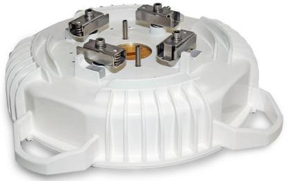
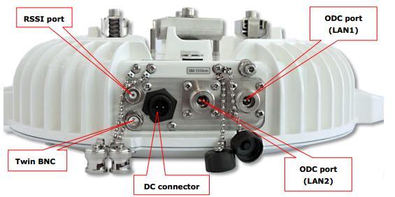
7 4.3 ODU radio Outdoor units Wi200 Hyperbridge ODU
8 Wi700 Hyperbridge ODU
9 5. Antenna Adjustment 5.1 Azimuth Adjustment Make coarse azimuth adjustment in the following way (shown in Fig 5.1): loosen the 4 nuts (No.1) of the Clamp (No.2) properly, and then push the whole structure slowly to make a rotation from 0 to 360 around the Mounting Pole. Use compass to determine the antenna s position if necessary, and then tighten the nuts (No.1). Make fine azimuth adjustment in the following way: loosen bolts (No. 5 and 6), and then adjust nuts (No.3) of Azimuth Adjustor back and forth slowly. Antenna can make fine azimuth adjustment from -15 to +15 ; tighten all the standard parts after the adjustment is done. 5.2 Elevation Adjustment Make elevation adjustment (shown in Fig 5.2): loosen the nuts (No.1), and then rotate Elevation Adjustor clockwise or counterclockwise. Antenna can make fine elevation adjustment from -15 to +15, tighten all the standard parts after the adjustment is done.
10 Make coarse elevation adjustment (shown in Fig 5.3): loosen the bolts (No.5). Use 1 & 4 thread holes, antenna can make elevation adjustment from +5 to +25. Use 2 & 3 thread holes, antenna can make elevation adjustment from -5 to -25. Tighten all the standard parts after the adjustment is done. 6. Antenna Assembly Finishing 6.1 Tighten all the standard parts after antenna assembly are done, regard it to torque of the standard parts is referred to the chapter Keep the antenna s bottom draining-hole open. Keep the top one sealed (shown in Fig.6.1 and Fig.6.1.1).
11 7. Appendix 1. Loosen M6X25 bolts (2PCS), and then put ODU into the Transition Section (shown in Fig 7.1). 2. Tighten all the standard parts (shown in Fig 7.2).
Remarks: Before Installation, please read the instruction carefully.
 60 cm antenna Z24A60T37301 Remarks: Before Installation, please read the instruction carefully. This instruction book is for the installation of 0.6m ultra-high performance microwave antenna. Installation,
Installation Instructions
 Installation Instructions For 4 foot / 1.2m Diameter Ultra-high Performance Antenna Model ADxxG-4-T2 Before Installation, please read the instructions carefully. This instruction guide covers the installation
Installation Instructions
 Installation Instructions For 0.2m Ultra-high Performance Antenna Model ADxxG-0-T2 Before Installation, please read these instructions carefully. This instruction guide is for the installation of 8 inch
Installation Instructions TMW Antenna Tower Mount for 4ft (1.2m) Antennas.
 Antennas.") Description The following pages show the steps required to assembly and fit the antenna mount to a vertical tower pipe of diameter 48 to 115 mm (1.9 to 4.5"). This mount provides ±20 azimuth or ±15 elevation
Description The following pages show the steps required to assembly and fit the antenna mount to a vertical tower pipe of diameter 48 to 115 mm (1.9 to 4.5"). This mount provides ±20 azimuth or ±15 elevation
These Installation Instructions are valid for antennas in the following version :
 Installation Instructions 2 ft Antennas (with M-Mount) SB, SBX (RFS CompactLine ) SP, SPF, SPX, SD, SDX, SU, SUX (RFS SlimLine ) PAL, DA, DAX, UA, UDA, UXA (Microwave) NMT 391-11(e) Antenna with integrated
Installation Instructions
 903-CIS0143-C Installation Instructions 0.9m Antenna LEAX Arkivator Telecom disclaims any liability for the results of improper or unsafe installation, inspection, maintenance, or removal practices. Torsgatan
Antenna Installation Manual
 High Performance Antennas 3 & 4 ft. (0.9 & 1.2 m) Antenna Installation Manual Please read the manual completely and carefully before installation. Instructions are intended for qualified and experienced
These Installation Instructions are valid for antennas in the following version:
 Installation Instructions 4 ft CompactLine Antennas (with E-Mount 200 km/h) SB, SBX NMT 480-12(e) These installation instructions have been written for qualified, skilled personnel. The antenna shall be
Instruction Sheet RADIO FREQUENCY SYSTEMS. Install. Instr. for Microwave Parabolic Antennas 2.4 m (8 ft) No Rev.
 No Rev.") Instruction Sheet No. 412764 Rev. B ECO 12469 Install. Instr. for Microwave Parabolic Antennas 2.4 m (8 ft) These Installation Instructions are valid for antennas in the following version: reflector 2.4
Instruction Sheet No. 412764 Rev. B ECO 12469 Install. Instr. for Microwave Parabolic Antennas 2.4 m (8 ft) These Installation Instructions are valid for antennas in the following version: reflector 2.4
Standard Pole Mount Parabolic Antenna Mounting Instructions 3 ft. (90cm) & 4 ft. (120cm)
 & 4 ft. (120cm)") 495 R Billerica Ave. N. Billerica, MA 01862 USA Tel: (978) 459-8800 Fax: (978) 459-3310 / 8814 www.radiowavesinc.com email: sales@radiowavesinc.com Standard Pole Mount Parabolic Antenna Mounting Instructions
495 R Billerica Ave. N. Billerica, MA 01862 USA Tel: (978) 459-8800 Fax: (978) 459-3310 / 8814 www.radiowavesinc.com email: sales@radiowavesinc.com Standard Pole Mount Parabolic Antenna Mounting Instructions
75 cm ODU (VS1300) Assembly Job Aid
 Assembly Job Aid") Summary This Job Aid covers: Verify AZ/EL Assembly Alignment Antenna Back Bracket Assembly Transport On Site Assembly This Job Aid supports all Technician audiences. This job aid covers the VS1200 ODU
Summary This Job Aid covers: Verify AZ/EL Assembly Alignment Antenna Back Bracket Assembly Transport On Site Assembly This Job Aid supports all Technician audiences. This job aid covers the VS1200 ODU
Installation Instructions 4 ft Antennas (with E-Mount) DA, DAX, UA, UDA, UXA SD, SDX, SU, SUX
 DA, DAX, UA, UDA, UXA SD, SDX, SU, SUX") Installation Instructions 4 ft Antennas (with E-Mount) DA, DAX, UA, UDA, UXA SD, SDX, SU, SUX NMT 553-01(e) These Installation Instructions are valid for antennas in the following version : Reflector Ø
Installation Instructions 4 ft Antennas (with E-Mount) DA, DAX, UA, UDA, UXA SD, SDX, SU, SUX NMT 553-01(e) These Installation Instructions are valid for antennas in the following version : Reflector Ø
75 cm ODU (VS1300 with the SurfBeam2 TRIA) Assembly Job Aid
 Assembly Job Aid") Summary This Job Aid covers: Verify AZ/EL Assembly Alignment Antenna Back Bracket Assembly TRIA, TRIA Bracket, and Boom Arm Assembly This Job Aid supports all Technician audiences. This job aid covers
Summary This Job Aid covers: Verify AZ/EL Assembly Alignment Antenna Back Bracket Assembly TRIA, TRIA Bracket, and Boom Arm Assembly This Job Aid supports all Technician audiences. This job aid covers
Installation Guide Flat Panel Antenna Mounting Kit For
 Installation Guide Flat Panel Antenna Mounting Kit For 103670-1 495R Billerica Ave. North Billerica, MA 01862 USA Tel (978)459-8800 fax (978)459-3310 / 8814 Email: sales@radiowaves.com www.radiowaves.com
STANDARD MICROWAVE COMBINER MODEL SMC-XX-X-HP-X
 SMC-XX-X-HP Standard Microwave Combiner STANDARD MICROWAVE COMBINER MODEL SMC-XX-X-HP-X Installation Manual Please read the manual completely and carefully before installation. Instructions are intended
INSTALLATION INSTRUCTION RRU DOUBLE LIGHT POLE MOUNT
 INSTALLATION INSTRUCTION RRU Double Light Pole Mount for installation of two RRU units on mast, towers or other vertical structures. CUE DEE YOUR INNOVATIVE PARTNER 1 CONTENTS 1. PRODUCT COVERED IN THIS
Pole Mount Installation Guide
 Pole Mount Installation Guide (No Fine Adjustment) 495R Billerica Ave. North Billerica, MA 01862 USA Tel (978)459-8800 fax (978)459-3310 / 8814 Email: sales@radiowaves.com www.radiowaves.com IMPORTANT!
Paradigm. Connect100 Installation Guide
 Paradigm GX Connect100 Installation Guide Paradigm GX Safe Use WARNING Radiation Hazard. Transmitter power levels are sufficient to cause blindness or other serious injury to body tissue. Do not power
Installation Guide. 2x2 MIMO Dish Antenna TL-ANT2424MD & TL-ANT5830MD
 Installation Guide 2x2 MIMO Dish Antenna TL-ANT2424MD & TL-ANT5830MD Contents Introduction 1 Specifications 1 Safety Notice 2 Package Contents 2 Installation Requirements 3 Hardware Overview 3 Hardware
ANTENNA EXPERTS. Website: AP MHz. 2.4 Meters 30dBi. Gain
 ANTENNA EXPERTS E-mail: info@antennaexperts.in Website: www.antennaexperts.in AP-180030 1700 1900 MHz. 2.4 Meters 30dBi. Gain INSTALLATION MANUAL GRID PARABOLIC ANTENNA NOTICE: Installation, maintenance
2 Pipe Clamp Bracket 3 11 M6 Screw with Tube M6 Hex Nut 2 4 M20 Flat Washer 4
 3842 Revision B, May 201 Mounting Kit, For Metro Cell Antennas MC-MNT-TOP-2 Mounting Kit GENERAL INFORMATION Top of pole mounting option Fits round members.3" to 8." (10 to 21 mm) pole diameter. PRE-INSTALLATION
Installation Guide For FPD Antenna
 Installation Guide For 104590-1 FPD.5-5.8-18 Antenna 495R Billerica Ave. North Billerica, MA 01862 USA Tel (978)459-8800 fax (978)459-3310 / 8814 Email: sales@radiowaves.com www.radiowaves.com IMPORTANT!
1.8 METER SERIES 1184 ANTENNA SYSTEM
 REVISION F January 10, 2002 ASSEMBLY MANUAL 1.8 METER SERIES 1184 ANTENNA SYSTEM PRODELIN CORPORATION 1500 Prodelin Drive Newton NC 28658 1.8 METER SERIES 1184 ANTENNA SYSTEM F Revised Address 1/10/02
Technical publication. Path alignment and cross polarization procedure for parabolic microwave antennas
 Technical publication Path alignment and cross polarization procedure for parabolic microwave antennas Contents 1.0 Introduction 3 2.0 Path alignment procedure 3 2.1 Setting azimuth marker 3 2.2 Test equipment
Mounting Instructions for Cisco Aironet 1550 Series Outdoor Access Point Pole-Mount Kits
 Mounting Instructions for Cisco Aironet 1550 Series Outdoor Access Point Pole-Mount Kits Date: April 2011 Part number: This document describes how to use the Cisco Aironet 1550 Series Outdoor Access Point
Cisco Aironet Dual-Band MIMO Wall-Mounted Omnidirectional Antenna (AIR-ANT2544V4M-R)
") Cisco Aironet Dual-Band MIMO Wall-Mounted Omnidirectional Antenna (AIR-ANT2544V4M-R) This document outlines the specifications for the Cisco Aironet 2.4-GHz/5-GHz Dual-Band MIMO Wall-Mounted Omnidirectional
Cisco Aironet Dual-Band MIMO Wall-Mounted Omnidirectional Antenna (AIR-ANT2544V4M-R) This document outlines the specifications for the Cisco Aironet 2.4-GHz/5-GHz Dual-Band MIMO Wall-Mounted Omnidirectional
1.2 METER SERIES 1130 Rx/O ANTENNA SYSTEM
 REVISION H April 20, 2016 ASSEMBLY MANUAL 1.2 METER SERIES 1130 Rx/O ANTENNA SYSTEM General Dynamics SATCOM Technologies 1700 Cable Drive NE Conover NC 28613 USA Phone 770-689-2040 www.gdsatcom.com 1.2
SAM. Model: STV-C65 LCD Mobile Visualized Stand Instruction Manual. Weight Capacity: 1251bs / 56.7kg Suits LCD Flat Panel Display: 42"-55" Page 20
 SAM Model: STV-C65 LCD Mobile Visualized Stand Instruction Manual Weight Capacity: 1251bs / 56.7kg Suits LCD Flat Panel Display: 42"-55" 20 Step 6 LCD Mobile Lift Stand Model: STV-C65 Cable management
On-Roof Mounting Sets for Flat-Plate Collectors
 Engineering Submittal Sheet Installation sets for collectors Fig. 1 Installation set for 2 collectors 1 basic installation set, 1 extension installation set Basic installation set for each collector array
1.8 METER SERIES 1194 ANTENNA SYSTEM
 January 14, 2002 REVISION G ASSEMBLY MANUAL 1.8 METER SERIES 1194 ANTENNA SYSTEM PRODELIN CORPORATION 1500 Prodelin Drive Newton NC 28658 1.8 METER SERIES 1194 ANTENNA SYSTEM G Revise Address 1/14/02 F
E4-WM5-Y525A00 MOUNTING INSTRUCTION
 RAM 2500/3500 4WD B8 5100 (Dual Steering Damper Kit) The installation of these steering dampers must be performed only by experienced and qualified personnel. Read and follow the installation instructions
SERIES M Ku-BAND Rx / Tx ANTENNA SYSTEM
 4096-432 June 15, 2011 REVISION D ASSEMBLY MANUAL SERIES 1125 1.2M Ku-BAND Rx / Tx ANTENNA SYSTEM General Dynamics 1500 PRODELIN DRIVE NEWTON, NC 28658 PRODELIN CORPORATION 4096-432 SERIES 1125 1.2M Ku-BAND
INSTRUCTION. Industrial Sewing Machines V7100/D,DE,F,ML W8100/D,DE,F,C W8042 W V7002-1S W8103-1S. No Third edition : March 2001
 INSTRUCTION Industrial Sewing Machines V7100/D,DE,F,ML W8100/D,DE,F,C W8042 W8042-1 V7002-1S W8103-1S Third edition : March 2001 No. 010012 INTRODUCTION Thank you for your purchasing Kansai Special's V.W
Installation Instructions
 Installation Instructions Feed Installation for 0.6m(2ft) Spread Spectrum Antennas Bulletin 239851 Revision F Antenna Assembly Sequence P2F/HP2F/PX2F/ HPX2F antenna 1 2 3 1a 1 Apply conductive grease (5)
Easy Step by Step Manual
 Easy Step by Step Manual Teletower Mini XL Wall-Floor installation The tower packages #1-#2-#3 Open Base Package #1 for the main tower parts. Here you see the three tower tubes (H-Head, M-Middle, F-Feed)
(6) Plastic Retainers. Passenger/Right. Passenger/Right Support Brackets
 Plastic Retainers. Passenger/Right. Passenger/Right Support Brackets") PART#R102580 PARTS LIST: 1 Driver/Left HD Running Board 4 8mm Bolt/Nut Plates 1 Passenger/Right HD Running Board 4 8mm Plastic Retainers 2 Driver/Left & Center Mount Bracket 14 8mm-1.25 x 30mm Hex Bolts
PART#R102580 PARTS LIST: 1 Driver/Left HD Running Board 4 8mm Bolt/Nut Plates 1 Passenger/Right HD Running Board 4 8mm Plastic Retainers 2 Driver/Left & Center Mount Bracket 14 8mm-1.25 x 30mm Hex Bolts
Constable Oak Extension Dining Table
 Constable Oak Extension Dining Table Assembly Instructions - Please keep for future reference 176/0325 Dimensions Width - 160/ 200cm Depth - 90cm Height - 75cm Important - Please read these instructions
08+ KAWASAKI KLR PD NERF
 08+ KAWASAKI KLR PD NERF 0505-1299 Before you begin, place the bike on a hard level surface where you have room to work. Lay out the parts included in this kit and compare to the parts list on page 5 of
LIGHT BEAM ANTENNA MaxRange Antenna Series Assembly Instructions MaxRange Plus Digital / High Definition Television Antennas
 LIGHT BEAM ANTENNA MaxRange Antenna Series Assembly Instructions MaxRange Plus Digital / High Definition Television Antennas Assembly Instructions 1 MaxRange Plus Antenna These instructions will lead you
Model POA-CHB-XL50. Assembly and Installation Manual. Projector Bracket. Contents. Be sure to consult with a qualified installation specialist
 Assembly and Installation Manual Projector Bracket Model POA-CHB-XL50 Be sure to consult with a qualified installation specialist This bracket is specifically for use with our projector. Be especially
Converting the MGL SERVO to a MGL CAPSTAN SERVO.
 Parts supplied in kit Converting the MGL SERVO to a MGL CAPSTAN SERVO. 1 x bracket, 1 x bracket clamp, 4 x cap head screws M4 x 8 1 x nut M6, 1 x washer M6, 1 x drum, 1 x shear screw M3, 2 x grub screws
4. Z-axis assembly. 4. Z-axis assembly. Written By: Josef Prusa manual.prusa3d.com Page 1 of 18
 4. Z-axis assembly Written By: Josef Prusa 2017 manual.prusa3d.com Page 1 of 18 Step 1 Get the necessary tools 13/17mm spanners 3.6mm flathead screwdriver Needle-nose pliers 2.5 and 1.5mm Allen key Step
Version 1.0 TWO PEOPLE BARBIE DREAMTOPIA ROBE 2 DOOR. REQUIRED
 Version 1.0 TWO PEOPLE BARBIE DREAMTOPIA ROBE 2 DOOR REQUIRED www.fantasticfurniture.com.au ENJOY Your purchase from Australia's Best Value Furniture Store www.fantasticfurniture.com.au PAGE 2 Assembly
QDV120 Operation and Pointing manual
 QDV120 Operation and Pointing manual MPAD1 Plus OP-080316-E1 page 1 Contents Item Description Page 1.0 Health and Safety for Operators and Installation Staff 3 2.0 Transit case Reflector/Mount/BUC/LNB
Instruction Manual for 98cm Elliptical Ka Antenna
 Instruction Manual for 98cm Elliptical Ka Antenna 98cm WB Issue 03 Caution This instruction leaflet will assist you in the correct installation of the product. Read it prior to starting any installation
Queen Wingback Bed King Wingback Bed
 Parts and Hardware List A. Side Rails with Attachment Hooks 2 pcs B. Foot Rail 1 pc C. Head Rail 1 pc D. Center Support Slat 1 pc E. Leg Supports 3 pcs F. Support Slats 4 pcs G. Flat Washers 8 pcs H. Lock
INSTALLATION INSTRUCTIONS
 Sheet 1 of 5 General: Upon receipt of fixture thoroughly inspect for any freight damage, which should be brought to the attention of the delivery carrier. Compare the catalog description listed on the
OTECO INC. MODEL ,000 PSI 4-1/16 PORT DM GATE VALVE MAINTENANCE MANUAL
 Page 1 of 7 OTECO INC. MODEL 45 4 5,000 PSI 4-1/16 PORT DM GATE VALVE MAINTENANCE MANUAL Page 2 of 7 TABLE OF CONTENTS 1. Assembly Blowout 2. Repair Kit Contents & Technical Specifications 3. Disassembly
MOUNTING INSTRUCTIONS CONCRETE PURLIN BRACKET
 CONCRETE PURLIN BRACKET VERSION MARCH 2015 GENERAL INSTRUCTIONS Safety: Systems may only be installed and operated by properly trained and technically suitable people (i.e. MCS accredited installers).
VIEWPOINT ALUMINUM RUNNING BOARD TOYOTA RAV4
 PARTS LIST: VIEWPOINT ALUMINUM RUNNING BOARD 1 Driver/Left Running Board 4 10-1.5mm x 50mm T-Bolt 1 Passenger/Right Running Board 12 10mm Plastic Retainers 1 Driver/Left Bracket 2 10-1.50mm x 40mm Hex
FBX1104P FBX1104 FBX1106P FBX1106
 FBX1104P FBX1104 FBX1106P FBX1106 Second edition : September 2004 No. 040037 INTRODUCTION Thank you for your purchasing Kansai Special's FBX Series. Read and study this instruction manual carefully before
4-Port Antenna Frequency Range Dual Polarization HPBW Adjust. Electr. DT
 Frequency Range Dual Polarization HPB Adjust. Electr. DT R1 698 960 Y1 1710 2690 1.5 10 2 8 set by hand or by optional RCU (Remote Control Unit) X 65 X 65 4-Port Antenna 698 960/1710 2690 65 /65 17/18.5dBi
1.2M Ku-BAND Rx/Tx SERIES 1132 ANTENNA SYSTEM
 August12, 2003 ASSEMBLY MANUAL Revision E 1.2M Ku-BAND Rx/Tx SERIES 1132 ANTENNA SYSTEM PRODELIN CORPORATION 1500 Prodelin Drive Newton NC 28658 1.2M Ku-BAND Rx/Tx SERIES 1132 ANTENNA SYSTEM E Revised
INSIDE PANEL NOT SHOWN TO DETAIL ANCHORING SYSTEM
 SIX INCH ALPHA MODULE INSTALLATION KEWAUNEE SCIENTIFIC CORPORATION SIX INCH ALPHA MODULE ANCHORING SYSTEM After Alpha module has been set in desired location. Adjust the four adjustment bolts until the
2009 ODU Point and Peak Job Aid
 Summary This Job Aid covers: Preparing the Antenna for Pointing and Peaking Point Elevation Set the Skew Point Azimuth Peak Azimuth Peak Elevation Push/Pull Test This Job Aid supports all Technician audiences.
6-Port Antenna Frequency Range Dual Polarization HPBW Adjust. Electr. DT set by hand or by optional RCU (Remote Control Unit)
") Frequency Range Dual Polarization HPB Adjust. Electr. DT 698 960 1710 2690 1710 2690 1.5 10 0 10 2 10 set by hand or by optional RCU (Remote Control Unit) X X 65 65 65 X 6-Port Antenna 698 960/1710 2690/1710
Frequency Range Dual Polarization HPB Adjust. Electr. DT 698 960 1710 2690 1710 2690 1.5 10 0 10 2 10 set by hand or by optional RCU (Remote Control Unit) X X 65 65 65 X 6-Port Antenna 698 960/1710 2690/1710
Model CR 146/440. ArrowAntennas.com Simply the Best. Corner Reflector for 146 & 440 MHz. (307)
") 911 E. Fox Farm Rd. #2 Cheyenne, WY 82007 ArrowAntennas.com Simply the Best (307) 222-4712 info@arrowantennas.com Corner Reflector for 146 & 440 MHz Guarantee No hassle refund If you are not completely
911 E. Fox Farm Rd. #2 Cheyenne, WY 82007 ArrowAntennas.com Simply the Best (307) 222-4712 info@arrowantennas.com Corner Reflector for 146 & 440 MHz Guarantee No hassle refund If you are not completely
Ceiling Tile Installations Part 1. Sheetrock Installations Part 2. WolfVision Support 2055 Sugarloaf Circle, Suite 125 Duluth, GA 30097
 Ceiling Tile Installations Part 1 Sheetrock Installations Part 2 WolfVision Support 2055 Sugarloaf Circle, Suite 125 Duluth, GA 30097 (877) 873-WOLF support@wolfvision.us 0 EYE Series Mounting Kit Part
6-Port Antenna Frequency Range Dual Polarization HPBW Adjust. Electr. DT set by hand or by optional RCU (Remote Control Unit)
") Frequency Range Dual Polarization HPB Adjust. Electr. DT 698 960 1710 2690 1710 2690 1 12 2 12 2 12 set by hand or by optional RCU (Remote Control Unit) X X 65 65 65 X 6-Port Antenna 698 960/1710 2690/1710
Frequency Range Dual Polarization HPB Adjust. Electr. DT 698 960 1710 2690 1710 2690 1 12 2 12 2 12 set by hand or by optional RCU (Remote Control Unit) X X 65 65 65 X 6-Port Antenna 698 960/1710 2690/1710
mila-wall (Series100) General Operating Instructions page 1 of 15
 General Operating Instructions page 1 of 15") mila-wall (Series100) General Operating Instructions page 1 of 15 Step #1: Before setting up walls, lower adjustable leveling feet on each panel approximately 1". This will allow access to the threaded
mila-wall (Series100) General Operating Instructions page 1 of 15 Step #1: Before setting up walls, lower adjustable leveling feet on each panel approximately 1". This will allow access to the threaded
Installation Job Aid (English) for Avaya WLAN 8100 series- WLAN AP 8120 with External Antenna
 for Avaya WLAN 8100 series- WLAN AP 8120 with External Antenna") Release 3.0 NN47251-311 Issue 02.01 June 2014 Installation Job Aid (English) for Avaya WLAN 8100 series- WLAN AP 8120 with External Antenna How to get help To access the complete range of services and
Release 3.0 NN47251-311 Issue 02.01 June 2014 Installation Job Aid (English) for Avaya WLAN 8100 series- WLAN AP 8120 with External Antenna How to get help To access the complete range of services and
8-Port Antenna Frequency Range Dual Polarization HPBW Adjust. Electr. DT
 Frequency Range Dual Polarization HPB Adjust. Electr. DT R1 790 960 B1 1710 1880 B2 1920 2170 Y1 2490 2690 X X X X 65 65 65 65 0.5 9.5 2 8 2 8 2 8 set by hand or by optional RCU (Remote Control Unit) 8-Port
Sliding Door Enclosure
 General Information Please inspect the product immediately upon rceipt for transit damage, missing packs or parts or damage. Damages reported outside the time period advised during your purchase will not
LIGHT BEAM ANTENNA MaxRange Antenna Series Assembly Instructions MaxRange Ultra Digital / High Definition Television Antennas
 LIGHT BEAM ANTENNA MaxRange Antenna Series Assembly Instructions MaxRange Ultra Digital / High Definition Television Antennas Assembly Instructions 1 MaxRange Ultra Antenna These instructions will lead
Mounting Accessories. Installation Guide. VIVOTEK SD83XXE Speed Dome
 VIVOTEK SD83XXE Speed Dome Mounting Accessories AM-116/117 Pendant Pipe AM-118 Pendant Head AM-221 Gooseneck AM-231 Parapet Mount AM-519 Pendant Adaptor Installation Guide Corresponding part numbers: AM-116:
model tsa-sa48 Sliding Crosscut Table installation guide
 model tsa-sa48 Sliding Crosscut Table installation guide A Note About Color Variations Among Anodized Aluminum Components Congratulations on the purchase of this SawStop Sliding Crosscut Table. We at SawStop
ASSEMBLY AND ADJUSTMENT
 EPPA MONITOR ARM EPPA Rev A 10/17 Model EPPA-XXX ASSEMBLY AND ADJUSTMENT EPPA MONITOR ARM PARTS AND TOOLS PLEASE REVIEW these instructions before beginning the assembly and adjustment procedures. Check
INSTALLATION INSTRUCTIONS DODGE RAM 2 & 4WD 1500 PART # P5058
 INSTALLATION INSTRUCTIONS 2009-13 DODGE RAM 2 & 4WD 1500 PART # P5058 PARTS LIST: Qty Description Qty Description 1 Grille Guard 12 12-1.75mm Hex Nuts 2 Upper Frame Mounting s (for trucks without tow hooks
Model CR146. ArrowAntennas.com Simply the Best. Corner Reflector for 146 MHz. (307)
") 911 E. Fox Farm Rd. #2 Cheyenne, WY 82007 ArrowAntennas.com Simply the Best (307) 222-4712 info@arrowantennas.com Corner Reflector for 146 MHz Guarantee No hassle refund If you are not completely satisfied
911 E. Fox Farm Rd. #2 Cheyenne, WY 82007 ArrowAntennas.com Simply the Best (307) 222-4712 info@arrowantennas.com Corner Reflector for 146 MHz Guarantee No hassle refund If you are not completely satisfied
MESA-HPX. Assembly and Installation Manual. w/appendix A for Prodelin Antenna. 901-Manual-MESA-HPX
 MESA-HPX Assembly and Installation Manual w/appendix A for Prodelin Antenna 901-Manual-MESA-HPX Rev 30 March 2011 2 INDEX Installation Cautions 4 Installation Pole Height Orientation of the Mount on the
INSTALLATION INSTRUCTIONS GRILLE GUARD RAM 1500 PART # 5058/5058-2
 INSTALLATION INSTRUCTIONS GRILLE GUARD PART # 5058/5058-2 PARTS LIST: Qty Description Qty Description 1 Grille Guard 8 12-1.75mm x 35mm Hex Bolts 2 Upper Frame Mounting s (for trucks without tow hooks
INSTALLATION INSTRUCTIONS
 AUTOMOTIVE PRODUCTS, INSTALLATION INSTRUCTIONS PLATINUM 4 OVAL STEP BAR (90 BENT END) APPLICATION: 2010-2015 Dodge Ram 2500/3500 Mega Cab PART NUMBER: 21-3570, 21-3575, 23-3570, 23-3575, 25-3570, 25-3575,
Single Band 125mm Profile Panel Antennas Installation and Operation Instructions Including APM-F-084-S4 & APM-T-085-S4 Mounting Kits
 General Single Band 125mm Profile Panel Antennas Installation and Operation Instructions Including APM-F-084-S4 & APM-T-085-S4 Mounting Kits This instruction sheet contains all necessary information required
UK10 UK11. First published: June No.KX03023
 UK10 UK11 First published: June 2003 No.KX03023 INTRODUCTION Thank you for purchasing Kansai Special s UK series machine. Please study this instruction manual carefully before operating the machine. 1.
IN 578. Tools Required. Torque Specification: 10mm Socket 7/16 Socket 1/2 Socket 1/2 Wrench 7/16 Wrench 1/8 Allen Wrench.
 Tools Required 2011-C Ford F250/F350 No Drilling into Vehicle is Required 10mm Socket 7/16 Socket 1/2 Socket 1/2 Wrench 7/16 Wrench 1/8 Allen Wrench FL277 x 1 Torque Specification: 1/4 Bolts - 6 Ft Lbs.
Installation and Operating Instructions
 INSTRUCTIONS Installation and Operating Instructions In these installation instructions is described the replacement of the elevating support with gas springs. This conversion kit applies to all California
Passenger/Right Center and Rear Support Brackets. Driver/Left Center and
 PARTS LIST: 1 Driver/Left HD Running Board 24 8mm x 24mm OD x 2mm Flat Washers 1 Passenger/Right HD Running Board 12 s 3 Driver/Left front, passenger center/rear Support Brackets 6 8mm-1.25 Hex Nuts 3
.98M Ku-BAND Rx/Tx ANTENNA SYSTEM
 Revision C January 2, 2002 ASSEMBLY MANUAL ANTENNA SYSTEM PRODELIN CORPORATION 1500 Prodelin Drive Newton NC 28658 ANTENNA SYSTEM C Revised Series text B Revised Address 1/2/02 RAH A Revise and Update
KAWASAKI KLRE PD NERF HTP4-8-5 & HIGHWAY PEGS HTP4-1-4B
 Thank you for purchasing Happy Trails products. Our products are proudly hand made in Boise Idaho, USA. If you have any questions or concerns about the installation of this product, please contact us directly
1.2M Ku-BAND Rx/Tx SERIES 1134 ANTENNA SYSTEM
 August 21, 1997 Revision D ASSEMBLY MANUAL 1.2M Ku-BAND Rx/Tx SERIES 1134 ANTENNA SYSTEM PRODELIN CORPORATION 1700 NE CABLE DRIVE CONOVER, NC 28613-0368 1.2M Ku-BAND Rx/Tx SERIES 1134 ANTENNA SYSTEM D
M2 Antenna Systems, Inc. Model No:
 M2 Antenna Systems, Inc. Model No: 400-600-10 SPECIFICATIONS: Model... 400-600-10 Frequency Range... 390 To 650 MHz *Gain... 12 To 13 dbic Front to back... 20 db Nominal Beamwidth... 46 Nominal Feed Impedance....
DO35 MAINTENANCE INSTRUCTIONS
 CUSTOMER INFORMATION SHEET NO. 038 DO35 MAINTENANCE INSTRUCTIONS (DO35 V3 LAUNCHED PRODUCTION JUNE 2017) Table of Contents 1.0 Replacing Spindle Bushes V3... 22 2.0 Replacing Locking Mechanism V3... 6
Tilting, Swiveling & Rotating Flat Panel Wall Mount
 Tilting, Swiveling & Rotating Flat Panel Wall Mount Model: VXA980TC +5 to -5 +5 to -5 Supports most 0-80 Flat Panel TVs Maximum Weight Capacity: 32 lbs. Supports VESA Sizes up to 600x500 For technical
INSTALLATION INSTRUCTIONS GRILLE GUARD 09-ON DODGE RAM PART #
 INSTALLATION INSTRUCTIONS GRILLE GUARD 09-ON DODGE RAM PART # PARTS LIST: Qty Description Qty Description 1 Grille Guard 8 12-1.75mm x 35mm Hex Bolts 2 Brackets (for trucks without 22 12mm x 30.1mm OD
2005 ODU Point & Peak Job Aid
 Summary This Job Aid covers: Preparing the Antenna for Pointing and Peaking Point Elevation Set the Skew Point Azimuth Peak Azimuth Peak Elevation Push/Pull Test This Job Aid supports all Technician audiences.
Rugged Ridge Engine Transmission Skid Plate JK
 Installation Time: 1-2 Hours Tools Required: Rugged Ridge Engine Transmission Skid Plate 2012-2017 JK Sockets: 16mm, 17mm, 18mm deep well Socket Wrench Wrenches: 16mm, 18mm Torque Wrench Drill ½ Drill
1. The electrodes are comprised of four main parts: the PEEK piece, glass rod, bolt and stainless steel rod.
 Assembly of dual immersion corrosion cell electrode mount 1. The electrodes are comprised of four main parts: the PEEK piece, glass rod, bolt and stainless steel rod. Figure 1. From left: PEEK piece, glass
Series 4 HV Single Monitor Lift Assembly Instructions
 6703 Zinser Street Schofield, WI 54476 6/13/17 Series 4 HV Single Monitor Lift Assembly Instructions Read all the instructions before beginning. Hardware Pack # 53368 Page1 OF 6 Tools Required for Assembly:
AR15 SUPER SLIM AND ULTRA SLIM FREE FLOAT RAIL SYSTEMS
 MUM066011803 AR15 SUPER SLIM AND ULTRA SLIM FREE FLOAT RAIL SYSTEMS Proudly Designed and Made in USA Super Lightweight, Flush Fitting, and Continuous with Flat Top AR15 Upper Receiver Features Integral
4-Port Antenna Frequency Range Dual Polarization HPBW Adjust. Electr. DT
 Frequency Range Dual Polarization HPB Adjust. Electr. DT R1 790 960 B1 1710 2180 0 14 0 8 set by hand or by optional RCU (Remote Control Unit) X 65 X 65 4-Port Antenna 790 960/1710 2180 65 /65 14.5/17.5dBi
INSTALLATION INSTRUCTIONS 6 OVAL BENT END SIDEBARS DODGE RAM 1500, CREW CAB PART#: /241533B
 PARTS LIST: 1 Driver/Left Sidebar 24 8mm x 24mm x 2mm Flat Washers 1 Passenger/Right Sidebar 12 8mm Lock Washers 3 Driver/left, Passenger Center and Rear 6 8mm Hex Nuts 3 INSTALLATION INSTRUCTIONS 6 OVAL
R-EVO MANUAL. English
 R-EVO MANUAL English 1 ENGLISH VERSION Adjusting the holster for your revolver With versatility, refined design, high quality, elegance and resistance - R-EVO, the new GR Holster for revolvers, supplies
TITAN-BIT KEY-CUTTING MACHINE INSTRUCTION MANUAL
 TITAN-BIT KEY-CUTTING MACHINE INSTRUCTION MANUAL Contents: 1 PRESENTATION AND GENERAL ASPECTS... 3 1.1 GENERAL POINTS... 3 1.2 TRANSPORT AND PACKING... 3 1.3 IDENTIFICATION LABEL... 3 2 CHARACTERISTICS
Sliding Crosscut Table installation guide
 Sliding Crosscut Table installation guide model tsa-sa48 A Note About Color Variations Among Anodized Aluminum Components Congratulations on the purchase of this SawStop Sliding Crosscut Table. We at SawStop
MULTI-ACTIVITY PLAY TABLE
 ASSEMBLY INSTRUCTIONS! WARNING: CHOKING HAZARD - Small parts. Not for children under 3 years.! CAUTION: Adult assembly required. C 2006 Melissa and Doug, Inc. All Rights Reserved www.melissaanddoug.com
White Quail Auto Trap
 White Quail Auto Trap WARNING SAFETY, STORAGE & USE IF THE MAIN SPRING IS ATTACHED AND THE TRAP ARM IS IN THE 6 O CLOCK POSITION, THE TRAP IS ARMED AND EXTREME CAUTION IS REQUIRED. TO DISARM, TURN THE
74CM KU-BAND TYPE 741 ANTENNA SYSTEM HIGH WIND with Factory Assembled Az/El Mount
 JULY 2016 Revision A ASSEMBLY MANUAL 8001114-01 74CM KU-BAND TYPE 741 ANTENNA SYSTEM HIGH WIND with Factory Assembled Az/El Mount A ORIGINAL RELEASE - EC-02522 JUL 2016 R. Thompson REV. DESCRIPTION DATE
Removing the Z-Axis lead screw
 Page 1 of 8 TITLE: Sabre Z-Axis Lead Screw Replacement Procedure Gerber FastFact #: 5048 Supplied by: Gerber Hardware Support Last Modified: June 14, 2007 Summary: Tools used: The following procedure explains
Fig. 2 DORMA-Glas Stand/Issue 02/03 Seite/Page 1/7
 FSW Installation instructions Track rail 75 x 72 mm 1. Ceiling substructure and installation of the track rail (Fig. 1): The track rail must be bolted over its entire length (including the stacking track
Projector Flush Mount
 Projector Flush Mount ABtUS SIGAPORE PTE LTD Model: AV819 www.abtussingapore.com Patent Pending Revision 21/05/2012 ABtUS SINGAPORE PTE LTD www.abtussingapore.com User Operation Guide IMPORTANT NOTES Thank