LAB II. INTRODUCTION TO LAB EQUIPMENT
|
|
|
- Baldric Harvey
- 5 years ago
- Views:
Transcription
 2430, the function generator Agilent")
1 1. OBJECTIVE LAB II. INTRODUCTION TO LAB EQUIPMENT In this lab you will learn how to properly operate the oscilloscope Keysight DSOX1102A, the Keithley Source Measure Unit (SMU) 2430, the function generator Agilent 33220A, and a bread board. 2. OVERVIEW This lab will take you through the basics of using all the lab equipment. The Lab procedure will test your comprehension of the background material, so be sure you have read and understood how to operate all the equipment. Information essential to your understanding of this lab: 1. Background Material Materials necessary for this Experiment 1. Standard testing station 2. Two resistors: 3.3 kω and 5.1 kω 3. BACKGROUND INFORMATION 3.1. BREADBOARD BASICS Breadboards are simply a set of pre-wired interconnects that aid you in the building of your circuits. By plugging a wire of one component into a hole you will connect it to all other components in that strip or bus. Using strips, buses, and jumper wires you can construct a circuit on your breadboard. You can tell which holes are connected in one node by the black lines connecting them in Figure 1. There are the component connection strips that run up and down and buses labeled with an A or B. After examining Figure 1 the use of a breadboard should be intuitive. Figure 1. A schematic diagram of the breadboard showing buses and strips. 1-1

2 3.2. KEITHLEY SOURCE MEASURE UNIT 2400 This section will instruct you on how to use the Keithley 2430 source measure unit (SMU). The Keithley SMU can be used as a voltage source, a current source, a voltmeter or ammeter. Examine the figure below before moving on to studying the main functions of the Keithley SMU. (See the Link: Lab Instrument Front Panels for more detailed images of all of the front panels of the three major pieces of equipment used in this laboratory to examine these panels in more detail) COMPLIANCE In order to properly operate the Keithley SMU 2430, you must understand the concept of compliance. Compliance is a safety feature incorporated in the Keithley SMU to protect the circuit components from unexpected high power of operation. It is a limiting factor input by the user. There are two types of compliance issues. When the output value is above the value preset by the user, then the CMPL blinks. To overcome this, you need to increase the compliance value. If the units displayed on the screen blink, it means the display range is less than the actual output range. You need to press AUTO button to overcome this. How to set the compliance? Press the Edit button twice. Use Range button and the arrow buttons to set the desired value. Figure 2. Front panel of the Keithley SMU VOLTAGE/CURRENT SOURCE CONFIGURATION In order to use the Keithley SMU as a voltage source or a current source, you need to follow the steps given below. 1. Press the V/I button in the Source group. 2. Press the EDIT button at the left of the front panel (see Figure 2). If you were successful, the voltage source value (V src /I src ) will start blinking. If it is not blinking press the EDIT button again. 3. To change the source value, you need to use the following buttons. and : The Up and Down arrows in the range group (at the bottom right side of the front panel next to Output On/Off light) are used to change the range of the source value. and : The Up and Down arrows in the source group are used to change the digit value. < and > : The Left and Right arrows in the EDIT group are used to select the digit you wish to alter. 4. Once you set the value, press Enter. 1-2

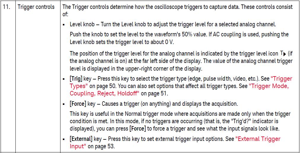
3 Once you have set the Keithley SMU as a voltage or a current source you need to push the ON/OFF button at the bottom right corner of the front panel. Check the compliance value in the display. If something blinks, there is a problem. In order for the Keithley SMU to work as a voltage source, you must set the output voltage that you want and set the compliance for output current. Similarly, in order for the Keithley SMU to work as a current source, you must set the output current that you want and set the compliance for output voltage VOLTMETER / AMMETER CONFIGURATION To configure the Keithley SMU as an Ammeter or a Voltmeter, use the following directions. Voltmeter instructions 1. Set the SMU up as a current source with no output current. 2. Then from the control panel area, press the V button in the MEAS group under the display. Ammeter instructions 1. Set the SMU up as a voltage source with no output voltage. 2. Then from the control panel area, press the I button in the MEAS group under the display Lab Exercise: 1. Connect the diode in your kit up to the Keithley SMU. Be sure to get the polarity correct. The longer lead is connected to the positive potential. 2. Set the Keithley SMU as a current source for the amount of current that your TA tells you. 3. Make sure that the compliance Voltage is set to 3 V. Make sure that the current will be less than 10 ma! If your LED burns out (and/or starts smoking), press the output button to turn off the output! DO NOT touch the LED or try to disconnect it with the output turned on! 4. If your current is < 100 μa, you probably have the LED connected backwards (the polarity is wrong.) 5. Turn on the Keithley SMU output and read the Voltage required to source the current. Tell your TA the value. (If you get it wrong, you will lose points.) 3.3. Keysight DSOX1102A OSCILLOSCOPE This section will instruct you on how to operate the Keysight DSOX1102A Oscilloscope OSCILLOSCOPE FRONT PANEL CONTROL The following is an extensive description of the controls used on the Keysight DSOX1102A Oscilloscope excerpted from the Keysight 1000X-Series Oscilloscope User s Guide. This User s Guide is also listed online for additional reference. The exact location of these controls on the front panel is shown in Figure 3 below. Please gain familiarity with the use of the Power switch, the Softkeys, the Entry knob, the [Auto Scale] key, the Horizontal and Acquisition controls, the Run Control keys, the Measure controls, the Vertical controls, and the Analog channel inputs discussed in more detail in the table below. These controls will be used repeatedly during this lab. The Cursors and Meas keys under the Measure Controls are particularly important for acquiring the data and are discussed in greater detail after the table. 1-3


4 Figure 3. Front panel of the Keysight DSOX1102A Oscilloscope. 1-4

5 1-5


6 1-6

7 MEASURING VOLTAGES AND TIME-RELATED PARAMETERS When measuring voltages with the oscilloscope, place the probes in parallel across the component where the voltage signal is being measured. Once you have the signal displayed on the screen, you can use buttons and keys to do the measurements. For measuring peak to peak, RMS, and DC voltages along with frequencies, time periods, and other time- related parameters use the following method: 1. Press the Auto Scale key to set the voltage and time parameters to an appropriate scale. 2. Press the Meas key under the Measure controls to take voltage and time measurements. 3. If no type of measurements have been saved to the scope at this point, then the scope will turn on an automatic frequency and V P-P measurement. Otherwise the oscilloscope will make the measurements using the previously saved type of measurements. 4. The scope can save up to four continuously updated measurements. Older measurements will be rolled off the screen. These measurements will be shown at the bottom of the screen. 5. To add a new type of measurement, first press the Type softkey located second from the top of the softkeys and then rotate the Entry knob until the type of measurement is highlighted. Then press the Entry knob, or alternatively press the Add Measurement softkey, to select this measurement. The data from the measurement will be shown on the right at the bottom of the screen. Repeat this procedure to generate additional measurements. 6. To change to a second oscilloscope channel, first press the Source softkey at the top of the softkeys and then rotate the Entry knob until the second source is highlighted. Then press the Entry knob to choose this channel. Then choose the appropriate type of measurement. Add additional measurements as required. 7. As an example, the frequency, V P-P, period, and V RMS of a sinusoidal signal with a V P-P of 5.3 V and a frequency of 100 Hz on Channel 1 was taken on the oscilloscope while a second sinusoidal signal was run on Channel 2 with a V P-P of 2.3 V and a frequency of 100 Hz. This measurement is shown directly below. No data has been generated for Channel 2. Similar measurements could be taken on Channel 2 by 1-7

 and Y-axis values (usually voltage) on a selected waveform source.")
8 changing the source to Source 2 and adding additional measurements. 8. You can clear any measurement by pressing Clear Meas at the bottom of the softkeys and then pressing the appropriate softkey to clear the appropriate measurement or to clear all measurements. For other measurements related to the voltage and time-related parameters, we use cursors. Cursors are horizontal and vertical markers that indicate X-axis values (usually time) and Y-axis values (usually voltage) on a selected waveform source. The position of these cursors can be moved by rotating the Cursors knob and the difference between the location of two cursors can be used to obtain either time-related parameters or voltage measurements. For making various voltage and time measurements with the cursors with the oscilloscope use the following method: 1. Press the Auto Scale key to set the voltage and time parameters to an appropriate scale. 2. Find the location of the Cursors knob located directly to the right of the Cursors key as shown below. 3. Press the Cursors key under the Measure controls to take voltage and time measurements using the cursors. 4. Press the Cursors knob and then rotate the knob until X1 is highlighted. Then press the Cursors knob to select this cursor. 5. Rotate the Cursors knob to position the cursor. 6. Then press the Cursors knob again and then rotate the knob until X2 is highlighted. Then press the Cursors knob to select this cursor. 7. Then rotate the Cursors knob again to position the the second cursor. 8. The difference in the position of these cursors can be used to determine the period and the frequency. 9. Press the Cursors knob and then rotate the knob until Y1 is highlighted. Then press the Cursors knob to select this cursor. 1-8

9 10. Rotate the Cursors knob to position the cursor. 11. Then press the Cursors knob again and then rotate the knob until Y2 is highlighted. Then press the Cursors knob to select this cursor. 12. Then rotate the Cursors knob again to position the the second cursor. 13. The difference in the position of these cursors can be used to determine the difference in the voltage between these two cursors 14. As an example, a signal generator was used to drive a square signal varying between 0 V and 1 V at a 20 khz frequency across a circuit formed in series with a 10 Ω resistor and a pn junction diode. The signal was measured between the output of the signal generator and ground on Channel 2 and between the node generated between the 10 Ω resistor and the pn junction diode and ground on Channel 1. The measured output is shown below where the difference between the steady state voltage of Channel 2 and Channel 1 was 175 mv and the frequency of the oscillating circuit as determined from where the signal generator goes from 0 V to 1 V is 20 khz with a period of 50 µs. Cursors are not always limited to the visible display. If you pan and zoom the waveform until the cursor is off screen, its value will not be changed, and if you pan the waveform back again it will have the cursor in the original place MEASURING CURRENTS This instrument can only measure current indirectly by reading the voltage across a resistor while it is in a circuit and then applying Ohm s Law to find the current or by using special probes using the Hall Effect to determine the current. If necessary, we will use Ohm s law to determine the current. If you have two signals and want to find the phase between similar points select the source of measurement for cursor 1 as channel 1 and the source for cursor 2 as channel 2. The difference readout is the delay between the two signals. If you divide that delay by the period then you have the phase value as a fraction of 360, or 2π radians. If you would like to represent that in degrees all you have to do is convert it from radians to degrees FUNCTION GENERATOR AGILENT 33220A The function generator is used to generate signals for your circuits. You will need to know how to set the function generator to get sine, square, triangle or ramp signals. In addition, you will have to 1-9

10 set up the frequency, the amplitude, offset voltage and the duty cycle. The default settings for this instrument are a sinewave of 1 khz, with an amplitude of 100 mv and a DC offset of 0.0 V. Figure 4. Front panel of the Agilent 33220A function generator. The function generator is very easy to use since each function has a specific button. If you want to select a waveform, just look for the button with the desired waveform such as a sine wave, a square wave, triangle wave, or ramp wave. Then, just press its button. All that you have to do now is set the parameters for the waveform. To set the frequency, amplitude, offset or the duty cycle you need to do the following: 1. Press the appropriate gray buttons beneath the display screen (Freq/Period, Ampl/Hi Level, Offset/Lo Level, or Duty Cycle). 2. You may enter the value one of two ways. a.) Turn the knob and the highlighted digit will change. You may select a different digit by using the < or the > buttons. b.) You can also key in the digit by using number buttons. 3. Press Output button on the bottom right of the front panel (right next to Sync cable) and make sure the light is on. IMPEDANCE MATCHING In order to make sure you read the exact value of the amplitude output by the function generator, You should make sure the output impedance of the function generator is matched to the impedance of the connected circuits. This function generator has 50 Ω output impedance. It has been configured by the manufacturer to deliver the voltage signal when a load of 50 Ω is attached to it. In the case of large impedance circuits the function generator may deliver up to twice the voltage that you have set it up to deliver. In our case, we use a series connected 5.1 kω resistor and 3.3 k Ω resistor, which is much higher than 50 Ω. Hence, when you set 1 V pp on the function generator, you will observe twice the amplitude (2 V pp ) on the oscilloscope. In order to overcome this, you need to set the function generator to have High Z output impedance. To do this, press the Utility button and press the output setup and you can change the output impedance to the High Z output mode. 1-10
11 4. PREPARATION There is no preparation for this lab except for reading and learning the background material. 5. PROCEDURE 5.1. FUNCTION GENERATOR AND OSCILLOSCOPE Turn on the function generator and the oscilloscope and perform the following tasks. 1. Build the circuit shown below in Figure Use the function generator to generate a signal with a frequency of 100 Hz and amplitude of 5 V. 3. Measure all voltages and all the time-related parameters (see section 3.3.2) across R 1. Since this is a single ended oscilloscope you cannot simply use one oscilloscope probe to measure the voltage across R1. You must make sure you use two oscilloscope probes with one used to measure the voltage between the positive side of R1 and ground (Channel 1) and the other used to measure the voltage between the positive side of R2 and ground (Channel 2) and then to subtract the Channel 2 signal from the Channel 1 signal in order to get the voltage across R1. Figure 5. Circuit being used for measuring the voltages and time parameters generated by the function generator with the oscilloscope KEITHLEY SMU This part of the lab experience will focus on the Keithley SMU. Notice that Figure 6 a) and b) are source transforms of each other. You should be able to compare and contrast the voltage and current measurements. Do all of the following. 1. Using the circuit of Figure 6 a), set up a Keithley SMU as a voltage source of 10 V DC. Use the second Keithley SMU to measure the voltages in R 1 and R 2. Measure the current in the circuit directly from the Keithley SMU used as the voltage source. 2. Using the circuit of Figure 6 b), set up a Keithley SMU as a current source of 5 ma DC. Set up the other Keithley to measure the current in R 3 and in R
12 Figure 6. Circuits for Keithley SMU to measure voltages and currents. 3. Measure the impedance of your two resistors using the Keithley SMU. Record the values and use these values to determine if your measurements were actually correct. 6. LAB REPORT Type a lab report with a cover sheet containing your name, class (including section number), date of the lab, and the report due date. Use the following outline to draft your lab report. Introduction: type a summary of the key features of the equipments used in this lab. Lab report: o Report all the measured data collected from this lab. (Make sure it is easily discernable which values are from a particular section of the procedure.) o Give theoretical descriptions for each section of the procedure and describe how the theory compared with the measured results. Include the circuit diagrams in your descriptions as necessary. Use the measured values for your resistors in finding the theoretical values. Conclusions: write up your conclusions for this lab. 1-12
LAB I. INTRODUCTION TO LAB EQUIPMENT
 1. OBJECTIVE LAB I. INTRODUCTION TO LAB EQUIPMENT In this lab you will learn how to properly operate the oscilloscope Agilent MSO6032A, the Keithley Source Measure Unit (SMU) 2430, the function generator
LAB I. INTRODUCTION TO LAB EQUIPMENT
 LAB I. INTRODUCTION TO LAB EQUIPMENT 1. OBJECTIVE In this lab you will learn how to properly operate the basic bench equipment used for characterizing active devices: 1. Oscilloscope (Keysight DSOX 1102A),
Lab #1 Lab Introduction
 Cir cuit s 212 Lab Lab #1 Lab Introduction Special Information for this Lab s Report Because this is a one-week lab, please hand in your lab report for this lab at the beginning of next week s lab. The
Introduction to basic laboratory instruments
 BEE 233 Laboratory-1 Introduction to basic laboratory instruments 1. Objectives To learn safety procedures in the laboratory. To learn how to use basic laboratory instruments: power supply, function generator,
Sept 13 Pre-lab due Sept 12; Lab memo due Sept 19 at the START of lab time, 1:10pm
 Sept 13 Pre-lab due Sept 12; Lab memo due Sept 19 at the START of lab time, 1:10pm EGR 220: Engineering Circuit Theory Lab 1: Introduction to Laboratory Equipment Pre-lab Read through the entire lab handout
University of Jordan School of Engineering Electrical Engineering Department. EE 204 Electrical Engineering Lab
 University of Jordan School of Engineering Electrical Engineering Department EE 204 Electrical Engineering Lab EXPERIMENT 1 MEASUREMENT DEVICES Prepared by: Prof. Mohammed Hawa EXPERIMENT 1 MEASUREMENT
Experiment #2: Introduction to Lab Equipment: Function Generator, Oscilloscope, and Multisim
 SCHOOL OF ENGINEERING AND APPLIED SCIENCE DEPARTMENT OF ELECTRICAL AND COMPUTER ENGINEERING ECE 2110: CIRCUIT THEORY LABORATORY Experiment #2: Introduction to Lab Equipment: Function Generator, Oscilloscope,
ECE 53A: Fundamentals of Electrical Engineering I
 ECE 53A: Fundamentals of Electrical Engineering I Laboratory Assignment #1: Instrument Operation, Basic Resistor Measurements and Kirchhoff s Laws Fall 2007 General Guidelines: - Record data and observations
EE 210: CIRCUITS AND DEVICES
 EE 210: CIRCUITS AND DEVICES LAB #3: VOLTAGE AND CURRENT MEASUREMENTS This lab features a tutorial on the instrumentation that you will be using throughout the semester. More specifically, you will see
EE 201 Lab! Tektronix 3021B function generator
 EE 201 Lab Tektronix 3021B function generator The function generator produces a time-varying voltage signal at its output terminal. The Tektronix 3021B is capable of producing several standard waveforms
Agilent 33220A Function Generator Tutorial
 Contents UNIVERSITY OF CALIFORNIA AT BERKELEY College of Engineering Department of Electrical Engineering and Computer Sciences EE105 Lab Experiments Agilent 33220A Function Generator Tutorial 1 Introduction
LAB 1: Familiarity with Laboratory Equipment (_/10)
") LAB 1: Familiarity with Laboratory Equipment (_/10) PURPOSE o gain familiarity with basic laboratory equipment oscilloscope, oscillator, multimeter and electronic components. EQUIPMEN (i) Oscilloscope
LAB 1: Familiarity with Laboratory Equipment (_/10) PURPOSE o gain familiarity with basic laboratory equipment oscilloscope, oscillator, multimeter and electronic components. EQUIPMEN (i) Oscilloscope
Notes on Experiment #1
 Notes on Experiment #1 Bring graph paper (cm cm is best) From this week on, be sure to print a copy of each experiment and bring it with you to lab. There will not be any experiment copies available in
ME 365 EXPERIMENT 1 FAMILIARIZATION WITH COMMONLY USED INSTRUMENTATION
 Objectives: ME 365 EXPERIMENT 1 FAMILIARIZATION WITH COMMONLY USED INSTRUMENTATION The primary goal of this laboratory is to study the operation and limitations of several commonly used pieces of instrumentation:
Group: Names: Resistor Band Colors Measured Value ( ) R 1 : 1k R 2 : 1k R 3 : 2k R 4 : 1M R 5 : 1M
 R 1 : 1k R 2 : 1k R 3 : 2k R 4 : 1M R 5 : 1M") 2.4 Laboratory Procedure / Summary Sheet Group: Names: (1) Select five separate resistors whose nominal values are listed below. Record the band colors for each resistor in the table below. Then connect
2.4 Laboratory Procedure / Summary Sheet Group: Names: (1) Select five separate resistors whose nominal values are listed below. Record the band colors for each resistor in the table below. Then connect
UNIVERSITY OF CALIFORNIA, SANTA BARBARA Department of Electrical and Computer Engineering. ECE 2A & 2B Laboratory Equipment Information
 UNIVERSITY OF CALIFORNIA, SANTA BARBARA Department of Electrical and Computer Engineering ECE 2A & 2B Laboratory Equipment Information Table of Contents Digital Multi-Meter (DMM)... 1 Features... 1 Using
Introduction to Basic Laboratory Instruments
 Introduction to Contents: 1. Objectives... 2 2. Laboratory Safety... 2 3.... 2 4. Using a DC Power Supply... 2 5. Using a Function Generator... 3 5.1 Turn on the Instrument... 3 5.2 Setting Signal Type...
EXAMPLE. Use this jack for the red test lead when measuring. current from 0 to 200mA. Figure P-1
 Digital Multimeters ON / OFF power switch Continuity / Diode Test Function Resistance Function Ranges from 200Ω to 200MΩ Transistor Test Function DC Current Function Ranges from 2mA to 20A. AC Current
Introduction to basic laboratory instruments
 Introduction to basic laboratory instruments 1. OBJECTIVES... 2 2. LABORATORY SAFETY... 2 3. BASIC LABORATORY INSTRUMENTS... 2 4. USING A DC POWER SUPPLY... 2 5. USING A FUNCTION GENERATOR... 3 5.1 TURN
Time-Varying Signals
 Time-Varying Signals Objective This lab gives a practical introduction to signals that varies with time using the components such as: 1. Arbitrary Function Generator 2. Oscilloscopes The grounding issues
EECS 318 Electronics Lab Laboratory #2 Electronic Test Equipment
 EECS 318 Electronics Lab Laboratory #2 Electronic Test Equipment Objectives: The purpose of this laboratory is to acquaint you with the electronic sources and measuring equipment you will be using throughout
Precalculations Individual Portion Introductory Lab: Basic Operation of Common Laboratory Instruments
 Name: Date of lab: Section number: M E 345. Lab 1 Precalculations Individual Portion Introductory Lab: Basic Operation of Common Laboratory Instruments Precalculations Score (for instructor or TA use only):
Experiment 1.A. Working with Lab Equipment. ECEN 2270 Electronics Design Laboratory 1
 .A Working with Lab Equipment Electronics Design Laboratory 1 1.A.0 1.A.1 3 1.A.4 Procedures Turn in your Pre Lab before doing anything else Setup the lab waveform generator to output desired test waveforms,
Combinational logic: Breadboard adders
 ! ENEE 245: Digital Circuits & Systems Lab Lab 1 Combinational logic: Breadboard adders ENEE 245: Digital Circuits and Systems Laboratory Lab 1 Objectives The objectives of this laboratory are the following:
Frequency and Time Domain Representation of Sinusoidal Signals
 Frequency and Time Domain Representation of Sinusoidal Signals By: Larry Dunleavy Wireless and Microwave Instruments University of South Florida Objectives 1. To review representations of sinusoidal signals
EENG-201 Experiment # 4: Function Generator, Oscilloscope
 EENG-201 Experiment # 4: Function Generator, Oscilloscope I. Objectives Upon completion of this experiment, the student should be able to 1. To become familiar with the use of a function generator. 2.
Laboratory 2 (drawn from lab text by Alciatore)
") Laboratory 2 (drawn from lab text by Alciatore) Instrument Familiarization and Basic Electrical Relations Required Components: 2 1k resistors 2 1M resistors 1 2k resistor Objectives This exercise is designed
Laboratory 2 (drawn from lab text by Alciatore) Instrument Familiarization and Basic Electrical Relations Required Components: 2 1k resistors 2 1M resistors 1 2k resistor Objectives This exercise is designed
Lab 0: Introduction to basic laboratory instruments. Revised by Dan Hoang & Tai-Chang Chen 03/30/2009
 Lab 0: Introduction to basic laboratory instruments Revised by Dan Hoang & Tai-Chang Chen 03/30/2009 1. Objectives 1. To learn safety procedures in the laboratory. 2. To learn how to use basic laboratory
Laboratory 3 (drawn from lab text by Alciatore)
") Laboratory 3 (drawn from lab text by Alciatore) The Oscilloscope Required Components: 1 10 resistor 2 100 resistors 2 lk resistors 1 2k resistor 2 4.7M resistors 1 0.F capacitor 1 0.1 F capacitor 1 1.0uF
Laboratory 3 (drawn from lab text by Alciatore) The Oscilloscope Required Components: 1 10 resistor 2 100 resistors 2 lk resistors 1 2k resistor 2 4.7M resistors 1 0.F capacitor 1 0.1 F capacitor 1 1.0uF
MASSACHUSETTS INSTITUTE OF TECHNOLOGY
 Name: MASSACHUSETTS INSTITUTE OF TECHNOLOGY 6.091 Hands-On Introduction to EE Lab Skills Laboratory No. 1 Oscilloscopes, Multimeter, Function Generator IAP 2008 1 Objective In this laboratory, you will
APPENDIX D DISCUSSION OF ELECTRONIC INSTRUMENTS
 APPENDIX D DISCUSSION OF ELECTRONIC INSTRUMENTS DC POWER SUPPLIES We will discuss these instruments one at a time, starting with the DC power supply. The simplest DC power supplies are batteries which
EXPERIMENT NUMBER 2 BASIC OSCILLOSCOPE OPERATIONS
 1 EXPERIMENT NUMBER 2 BASIC OSCILLOSCOPE OPERATIONS The oscilloscope is the most versatile and most important tool in this lab and is probably the best tool an electrical engineer uses. This outline guides
Lab 13 AC Circuit Measurements
 Lab 13 AC Circuit Measurements Objectives concepts 1. what is impedance, really? 2. function generator and oscilloscope 3. RMS vs magnitude vs Peak-to-Peak voltage 4. phase between sinusoids skills 1.
Introduction to Lab Instruments
 ECE316, Experiment 00, 2017 Communications Lab, University of Toronto Introduction to Lab Instruments Bruno Korst - bkf@comm.utoronto.ca Abstract This experiment will review the use of three lab instruments
Laboratory 2. Lab 2. Instrument Familiarization and Basic Electrical Relations. Required Components: 2 1k resistors 2 1M resistors 1 2k resistor
 Laboratory 2 nstrument Familiarization and Basic Electrical Relations Required Components: 2 1k resistors 2 1M resistors 1 2k resistor 2.1 Objectives This exercise is designed to acquaint you with the
The University of Jordan Mechatronics Engineering Department Electronics Lab.( ) Experiment 1: Lab Equipment Familiarization
 Experiment 1: Lab Equipment Familiarization") The University of Jordan Mechatronics Engineering Department Electronics Lab.(0908322) Experiment 1: Lab Equipment Familiarization Objectives To be familiar with the main blocks of the oscilloscope and
The University of Jordan Mechatronics Engineering Department Electronics Lab.(0908322) Experiment 1: Lab Equipment Familiarization Objectives To be familiar with the main blocks of the oscilloscope and
EE 201 Function / Arbitrary Waveform Generator and Oscilloscope Tutorial
 EE 201 Function / Arbitrary Waveform Generator and Oscilloscope Tutorial 1 This is a programmed learning instruction manual. It is written for the Agilent DSO3202A Digital Storage Oscilloscope. The prerequisite
ECE 2274 Lab 1 (Intro)
") ECE 2274 Lab 1 (Intro) Richard Dumene: Spring 2018 Revised: Richard Cooper: Spring 2018 Forward (DO NOT TURN IN) The purpose of this lab course is to familiarize you with high-end lab equipment, and train
ECE 2274 Lab 1 (Intro) Richard Dumene: Spring 2018 Revised: Richard Cooper: Spring 2018 Forward (DO NOT TURN IN) The purpose of this lab course is to familiarize you with high-end lab equipment, and train
Sonoma State University Department of Engineering Science Spring 2017
 EE 110 Introduction to Engineering & Laboratory Experience Saeid Rahimi, Ph.D. Lab 4 Introduction to AC Measurements (I) AC signals, Function Generators and Oscilloscopes Function Generator (AC) Battery
A semester of Experiments for ECE 225
 A semester of Experiments for ECE 225 Contents General Lab Instructions... 3 Notes on Experiment #1... 4 ECE 225 Experiment #1 Introduction to the function generator and the oscilloscope... 5 Notes on
Laboratory Equipment Instruction Manual 2011
 University of Toronto Department of Electrical and Computer Engineering Instrumentation Laboratory GB341 Laboratory Equipment Instruction Manual 2011 Page 1. Wires and Cables A-2 2. Protoboard A-3 3. DC
The oscilloscope and RC filters
 (ta initials) first name (print) last name (print) brock id (ab17cd) (lab date) Experiment 4 The oscilloscope and C filters The objective of this experiment is to familiarize the student with the workstation
A semester of Experiments for ECE 225
 A semester of Experiments for ECE 225 Contents General Lab Instructions... 3 Notes on Experiment #1... 4 ECE 225 Experiment #1 Introduction to the function generator and the oscilloscope... 5 Notes on
Parts to be supplied by the student: Breadboard and wires IRLZ34N N-channel enhancement-mode power MOSFET transistor
 University of Utah Electrical & Computer Engineering Department ECE 1250 Lab 3 Electronic Speed Control and Pulse Width Modulation A. Stolp, 12/31/12 Rev. Objectives 1 Introduce the Oscilloscope and learn
UNIVERSITY OF CALIFORNIA, BERKELEY. EE40: Introduction to Microelectronic Circuits Lab 1. Introduction to Circuits and Instruments Guide
 UNERSTY OF CALFORNA, BERKELEY EE40: ntroduction to Microelectronic Circuits Lab 1 ntroduction to Circuits and nstruments Guide 1. Objectives The electronic circuit is the basis for all branches of electrical
LABORATORY 4. Palomar College ENGR210 Spring 2017 ASSIGNED: 3/21/17
 LABORATORY 4 ASSIGNED: 3/21/17 OBJECTIVE: The purpose of this lab is to evaluate the transient and steady-state circuit response of first order and second order circuits. MINIMUM EQUIPMENT LIST: You will
Lab 2: Linear and Nonlinear Circuit Elements and Networks
 OPTI 380B Intermediate Optics Laboratory Lab 2: Linear and Nonlinear Circuit Elements and Networks Objectives: Lean how to use: Function of an oscilloscope probe. Characterization of capacitors and inductors
AME140 Lab #2 INTRODUCTION TO ELECTRONIC TEST EQUIPMENT AND BASIC ELECTRONICS MEASUREMENTS
 INTRODUCTION TO ELECTRONIC TEST EQUIPMENT AND BASIC ELECTRONICS MEASUREMENTS The purpose of this document is to guide students through a few simple activities to increase familiarity with basic electronics
University of Utah Electrical & Computer Engineering Department ECE 2210/2200 Lab 4 Oscilloscope
 University of Utah Electrical & Computer Engineering Department ECE 2210/2200 Lab 4 Oscilloscope Objectives 1 Introduce the Oscilloscope and learn some uses. 2 Observe Audio signals. 3 Introduce the Signal
Lab 3: RC Circuits. Construct circuit 2 in EveryCircuit. Set values for the capacitor and resistor to match those in figure 2 and set the frequency to
 Lab 3: RC Circuits Prelab Deriving equations for the output voltage of the voltage dividers you constructed in lab 2 was fairly simple. Now we want to derive an equation for the output voltage of a circuit
CHAPTER 6. Motor Driver
 CHAPTER 6 Motor Driver In this lab, we will construct the circuitry that your robot uses to drive its motors. However, before testing the motor circuit we will begin by making sure that you are able to
Laboratory Project 1a: Power-Indicator LED's
 2240 Laboratory Project 1a: Power-Indicator LED's Abstract-You will construct and test two LED power-indicator circuits for your breadboard in preparation for building the Electromyogram circuit in Lab
EE 3302 LAB 1 EQIUPMENT ORIENTATION
 EE 3302 LAB 1 EQIUPMENT ORIENTATION Pre Lab: Calculate the theoretical gain of the 4 th order Butterworth filter (using the formula provided. Record your answers in Table 1 before you come to class. Introduction:
Waveform Generators and Oscilloscopes. Lab 6
 Waveform Generators and Oscilloscopes Lab 6 1 Equipment List WFG TEK DPO 4032A (or MDO3012) Resistors: 10kΩ, 1kΩ Capacitors: 0.01uF 2 Waveform Generators (WFG) The WFG supplies a variety of timevarying
EXPERIMENT 1 PRELIMINARY MATERIAL
 EXPERIMENT 1 PRELIMINARY MATERIAL BREADBOARD A solderless breadboard, like the basic model in Figure 1, consists of a series of square holes, and those columns of holes are connected to each other via
EGRE 101 DC Motor II
 EGRE 101 DC Motor II Preamble In this week s laboratory exercise you will become familiar with: Converting a circuit schematic to a physical circuit implementation Measuring physical quantities relevant
Group: Names: (1) In this step you will examine the effects of AC coupling of an oscilloscope.
 In this step you will examine the effects of AC coupling of an oscilloscope.") 3.5 Laboratory Procedure / Summary Sheet Group: Names: (1) In this step you will examine the effects of AC coupling of an oscilloscope. Set the function generator to produce a 5 V pp 1kHz sinusoidal output.
3.5 Laboratory Procedure / Summary Sheet Group: Names: (1) In this step you will examine the effects of AC coupling of an oscilloscope. Set the function generator to produce a 5 V pp 1kHz sinusoidal output.
Name: Resistors and Basic Resistive Circuits. Objective: To gain experience with data acquisition proto-boards physical resistors. Table of Contents:
 Objective: To gain experience with data acquisition proto-boards physical resistors Table of Contents: Name: Resistors and Basic Resistive Circuits Pre-Lab Assignment 1 Background 2 National Instruments
Physics 120 Lab 1 (2018) - Instruments and DC Circuits
 - Instruments and DC Circuits") Physics 120 Lab 1 (2018) - Instruments and DC Circuits Welcome to the first laboratory exercise in Physics 120. Your state-of-the art equipment includes: Digital oscilloscope w/usb output for SCREENSHOTS.
Physics 120 Lab 1 (2018) - Instruments and DC Circuits Welcome to the first laboratory exercise in Physics 120. Your state-of-the art equipment includes: Digital oscilloscope w/usb output for SCREENSHOTS.
EE 210 Lab Exercise #3 Introduction to PSPICE
 EE 210 Lab Exercise #3 Introduction to PSPICE Appending 4 in your Textbook contains a short tutorial on PSPICE. Additional information, tutorials and a demo version of PSPICE can be found at the manufacturer
PHYSICS 171 UNIVERSITY PHYSICS LAB II. Experiment 4. Alternating Current Measurement
 PHYSICS 171 UNIVERSITY PHYSICS LAB II Experiment 4 Alternating Current Measurement Equipment: Supplies: Oscilloscope, Function Generator. Filament Transformer. A sine wave A.C. signal has three basic properties:
ECE 201 LAB 8 TRANSFORMERS & SINUSOIDAL STEADY STATE ANALYSIS
 Version 1.1 1 of 8 ECE 201 LAB 8 TRANSFORMERS & SINUSOIDAL STEADY STATE ANALYSIS BEFORE YOU BEGIN PREREQUISITE LABS Introduction to MATLAB Introduction to Lab Equipment Introduction to Oscilloscope Capacitors,
INTRODUCTION TO ENGINEERING AND LABORATORY EXPERIENCE Spring, 2015
 INTRODUCTION TO ENGINEERING AND LABORATORY EXPERIENCE Spring, 2015 Saeid Rahimi, Ph.D. Jack Ou, Ph.D. Engineering Science Sonoma State University A SONOMA STATE UNIVERSITY PUBLICATION CONTENTS 1 Electronic
Lab #5 Steady State Power Analysis
 Lab #5 Steady State Power Analysis Steady state power analysis refers to the power analysis of circuits that have one or more sinusoid stimuli. This lab covers the concepts of RMS voltage, maximum power
EE431 Lab 1 Operational Amplifiers
 Feb. 10, 2015 Report all measured data and show all calculations Introduction The purpose of this laboratory exercise is for the student to gain experience with measuring and observing the effects of common
USE OF BASIC ELECTRONIC MEASURING INSTRUMENTS Part II, & ANALYSIS OF MEASUREMENT ERROR 1
 EE 241 Experiment #3: USE OF BASIC ELECTRONIC MEASURING INSTRUMENTS Part II, & ANALYSIS OF MEASUREMENT ERROR 1 PURPOSE: To become familiar with additional the instruments in the laboratory. To become aware
54645D. Mixed Signal Oscilloscope
 54645D Mixed Signal Oscilloscope Page 1 of 42 Instructions for the use of the 54645D Mixed Signal Oscilloscope This pamphlet is intended to give you (the student) an overview on the use of the 54645D Mixed
EE EXPERIMENT 1 (2 DAYS) BASIC OSCILLOSCOPE OPERATIONS INTRODUCTION DAY 1
 BASIC OSCILLOSCOPE OPERATIONS INTRODUCTION DAY 1") EE 2101 - EXPERIMENT 1 (2 DAYS) BASIC OSCILLOSCOPE OPERATIONS INTRODUCTION The oscilloscope is the most versatile and most important tool in this lab and is probably the best tool an electrical engineer
EE 2101 - EXPERIMENT 1 (2 DAYS) BASIC OSCILLOSCOPE OPERATIONS INTRODUCTION The oscilloscope is the most versatile and most important tool in this lab and is probably the best tool an electrical engineer
Lab: Operational Amplifiers
 Page 1 of 6 Laboratory Goals Familiarize students with Integrated Circuit (IC) construction on a breadboard Introduce the LM 741 Op-amp and its applications Design and construct an inverting amplifier
Exercise 1: AC Waveform Generator Familiarization
 Exercise 1: AC Waveform Generator Familiarization EXERCISE OBJECTIVE When you have completed this exercise, you will be able to operate an ac waveform generator by using equipment provided. You will verify
Introduction to Electronic Equipment
 Introduction to Electronic Equipment INTRODUCTION This semester you will be exploring electricity and magnetism. In order to make your time in here more instructive we ve designed this laboratory exercise
EXPERIMENT 2 DIGITAL STORAGE OSCILLOSCOPE
 EXPERIMENT 2 DIGITAL STORAGE OSCILLOSCOPE 2.1 Objective: In this experiment, you will learn the basic usage of digital storage oscilloscope (DSO) of GW Instek Technologies. More specifically you will learn,
Notes on Experiment #2
 Notes on Experiment #2 The purpose of this experiment is to get some practice measuring voltage using the oscilloscope. You will be practicing direct and differential measuring techniques. You will also
ECE65 Introduction to the Function Generator and the Oscilloscope Created by: Eldridge Alcantara (Spring 2007)
") ECE65 Introduction to the Function Generator and the Oscilloscope Created by: Eldridge Alcantara (Spring 2007) I. Getting Started with the Function Generator OUTPUT Red Clip Small Black Clip 1) Turn on
ECE65 Introduction to the Function Generator and the Oscilloscope Created by: Eldridge Alcantara (Spring 2007) I. Getting Started with the Function Generator OUTPUT Red Clip Small Black Clip 1) Turn on
ET 304A Laboratory Tutorial-Circuitmaker For Transient and Frequency Analysis
 ET 304A Laboratory Tutorial-Circuitmaker For Transient and Frequency Analysis All circuit simulation packages that use the Pspice engine allow users to do complex analysis that were once impossible to
EC310 Security Exercise 20
 EC310 Security Exercise 20 Introduction to Sinusoidal Signals This lab demonstrates a sinusoidal signal as described in class. In this lab you will identify the different waveform parameters for a pure
BME/ISE 3511 Laboratory One - Laboratory Equipment for Measurement. Introduction to biomedical electronic laboratory instrumentation and measurements.
 BME/ISE 3511 Laboratory One - Laboratory Equipment for Measurement Learning Objectives: Introduction to biomedical electronic laboratory instrumentation and measurements. Supplies and Components: Breadboard
Tektronix Courseware. Academic Labs. Sample Labs from Popular Electrical and Electronics Engineering Curriculum
 Tektronix Courseware Academic Labs Sample Labs from Popular Electrical and Electronics Engineering Curriculum March 3, 2014 HalfWaveRectifier -- Overview OBJECTIVES After performing this lab exercise,
University of California, San Diego Department of Electrical and Computer Engineering
 University of California, San Diego Department of Electrical and Computer Engineering Part One: Introduction of Lab TAs ECE65, Spring 2007 Lab 0, ECE 65 Lab Orientation 1) James Liao, geniojames@yahoo.com
EE-4022 Experiment 2 Amplitude Modulation (AM)
") EE-4022 MILWAUKEE SCHOOL OF ENGINEERING 2015 Page 2-1 Student objectives: EE-4022 Experiment 2 Amplitude Modulation (AM) In this experiment the student will use laboratory modules to implement operations
EE-4022 MILWAUKEE SCHOOL OF ENGINEERING 2015 Page 2-1 Student objectives: EE-4022 Experiment 2 Amplitude Modulation (AM) In this experiment the student will use laboratory modules to implement operations
Lab 1: Basic Lab Equipment and Measurements
 Abstract: Lab 1: Basic Lab Equipment and Measurements This lab exercise introduces the basic measurement instruments that will be used throughout the course. These instruments include multimeters, oscilloscopes,
EK 307 Lab: Light-Emitting Diodes. In-lab Assignment (Complete Level 1 and additionally level 2 if you choose to):
:") EK 307 Lab: Light-Emitting Diodes Laboratory Goal: To explore the characteristics of the light emitting diode. Learning Objectives: Voltage, Current, Power, and Instrumentation. Suggested Tools: Voltage
EK 307 Lab: Light-Emitting Diodes Laboratory Goal: To explore the characteristics of the light emitting diode. Learning Objectives: Voltage, Current, Power, and Instrumentation. Suggested Tools: Voltage
1. Hand Calculations (in a manner suitable for submission) For the circuit in Fig. 1 with f = 7.2 khz and a source vin () t 1.
 For the circuit in Fig. 1 with f = 7.2 khz and a source vin () t 1.") Objectives The purpose of this laboratory project is to introduce to equipment, measurement techniques, and simulations commonly used in AC circuit analysis. In this laboratory session, each student will:
Objectives The purpose of this laboratory project is to introduce to equipment, measurement techniques, and simulations commonly used in AC circuit analysis. In this laboratory session, each student will:
Appendix A: Laboratory Equipment Manual
 Appendix A: Laboratory Equipment Manual 1. Introduction: This appendix is a manual for equipment used in experiments 1-8. As a part of this series of laboratory exercises, students must acquire a minimum
Diodes This week, we look at switching diodes, LEDs, and diode rectification. Be sure to bring a flash drive for recording oscilloscope traces.
 Diodes This week, we look at switching diodes, LEDs, and diode rectification. Be sure to bring a flash drive for recording oscilloscope traces. 1. Basic diode characteristics Build the circuit shown in
Lab 6 Instrument Familiarization
 Lab 6 Instrument Familiarization What You Need To Know: Voltages and currents in an electronic circuit as in a CD player, mobile phone or TV set vary in time. Throughout todays lab you will investigate
Lab Equipment EECS 311 Fall 2009
 Lab Equipment EECS 311 Fall 2009 Contents Lab Equipment Overview pg. 1 Lab Components.. pg. 4 Probe Compensation... pg. 8 Finite Instrumentation Impedance. pg.10 Simulation Tools..... pg. 10 1 - Laboratory
PHASORS AND PHASE SHIFT CIRCUITS
 PHASORS AND PHASE SHIFT CIRCUITS YOUR NAME GTA S SIGNATURE LAB MEETING TIME PHASOR CIRCUIT 4. Assemble the series RC circuit with the following circuit element values: C = 0.027 μf R = 10 kω v s (t) =
Non_Inverting_Voltage_Follower -- Overview
 Non_Inverting_Voltage_Follower -- Overview Non-Inverting, Unity-Gain Amplifier Objectives: After performing this lab exercise, learner will be able to: Understand and comprehend working of opamp Design
Instrument Usage in Circuits Lab
 Instrument Usage in Circuits Lab This document contains descriptions of the various components and instruments that will be used in Circuit Analysis laboratory. Descriptions currently exist for the following
Revision: Jan 29, E Main Suite D Pullman, WA (509) Voice and Fax
 Voice and Fax") Revision: Jan 29, 2011 215 E Main Suite D Pullman, WA 99163 (509) 334 6306 Voice and Fax Overview The purpose of this lab assignment is to provide users with an introduction to some of the equipment which
Revision: Jan 29, 2011 215 E Main Suite D Pullman, WA 99163 (509) 334 6306 Voice and Fax Overview The purpose of this lab assignment is to provide users with an introduction to some of the equipment which
332:223 Principles of Electrical Engineering I Laboratory Experiment #2 Title: Function Generators and Oscilloscopes Suggested Equipment:
 RUTGERS UNIVERSITY The State University of New Jersey School of Engineering Department Of Electrical and Computer Engineering 332:223 Principles of Electrical Engineering I Laboratory Experiment #2 Title:
LABORATORY 3 v3 CIRCUIT ELEMENTS
 University of California Berkeley Department of Electrical Engineering and Computer Sciences EECS 100, Professor Leon Chua LABORATORY 3 v3 CIRCUIT ELEMENTS The purpose of this laboratory is to familiarize
ENGR 210 Lab 6 Use of the Function Generator & Oscilloscope
 ENGR 210 Lab 6 Use of the Function Generator & Oscilloscope In this laboratory you will learn to use two additional instruments in the laboratory, namely the function/arbitrary waveform generator, which
Lab 2: Common Base Common Collector Design Exercise
 CSUS EEE 109 Lab - Section 01 Lab 2: Common Base Common Collector Design Exercise Author: Bogdan Pishtoy / Lab Partner: Roman Vermenchuk Lab Report due March 26 th Lab Instructor: Dr. Kevin Geoghegan 2016-03-25
Equipment: You will use the bench power supply, function generator and oscilloscope.
 EE203 Lab #0 Laboratory Equipment and Measurement Techniques Purpose Your objective in this lab is to gain familiarity with the properties and effective use of the lab power supply, function generator
LLS - Introduction to Equipment
 Published on Advanced Lab (http://experimentationlab.berkeley.edu) Home > LLS - Introduction to Equipment LLS - Introduction to Equipment All pages in this lab 1. Low Light Signal Measurements [1] 2. Introduction
ECE 2274 Lab 2. Your calculator will have a setting that will automatically generate the correct format.
 ECE 2274 Lab 2 Forward (DO NOT TURN IN) You are expected to use engineering exponents for all answers (p,n,µ,m, N/A, k, M, G) and to give each with a precision between one and three leading digits and
Notes on Experiment #3
 Notes on Experiment #3 This week you learn to measure voltage, current, and resistance with the digital multimeter (DMM) You must practice measuring each of these quantities (especially current) as much
48520 Electronics and Circuits. Lab Notes
 Family Name: First Name: 48520 Electronics and Circuits Lab Notes 2015 R R L V i L V o R 2 10 k +15 V 10 nf R 1 1 k v 1 2 3 7 10 F 6 TL071 4 10 F v 2 v S 500 mv pp 1.0 khz 10 nf -15 V PMcL i Introduction