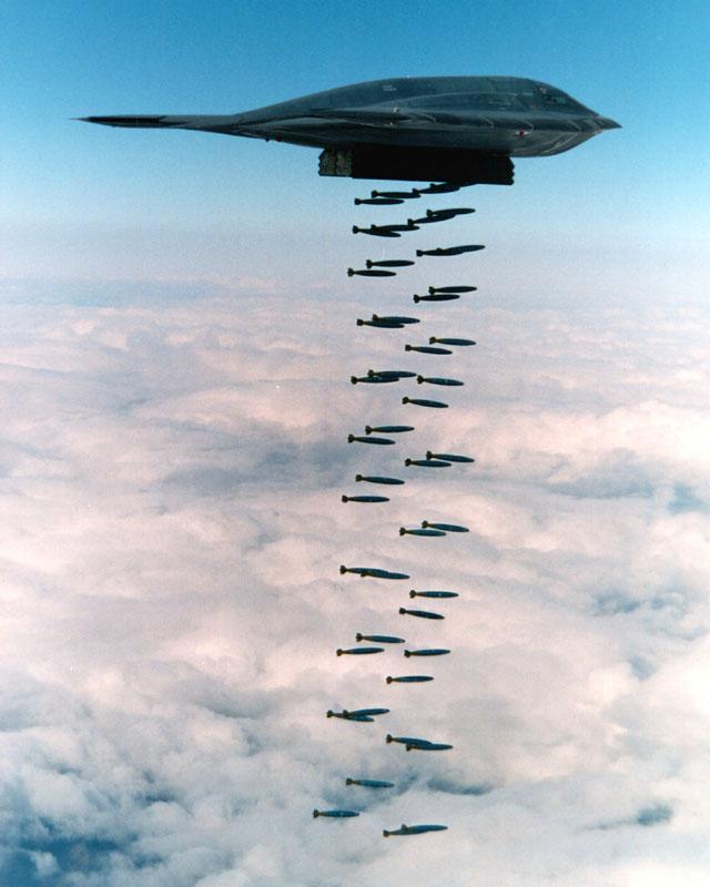
AircraftScatterSharp New Features
|
|
|
- Alison Bethany Bishop
- 5 years ago
- Views:
Transcription
1
2
3 Aircraft Scatter Is using aircraft to redirect or scatter RF that would otherwise be lost in space Increases Communications Distance Has increasing advantage over troposcatter as frequency increases Has increasing advantage as distance increases, up to ~ 900 km (560 miles) Truly a weak-signal mode
4
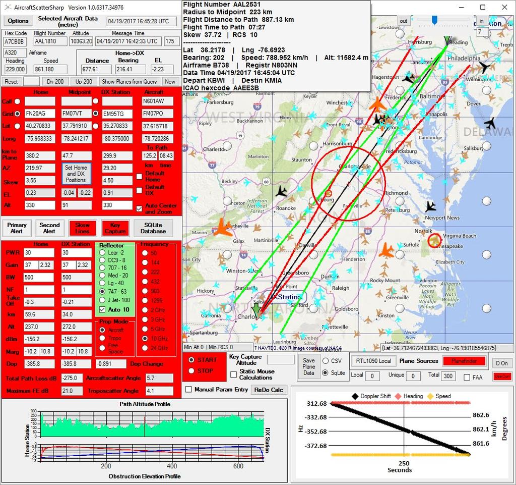
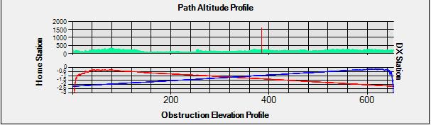
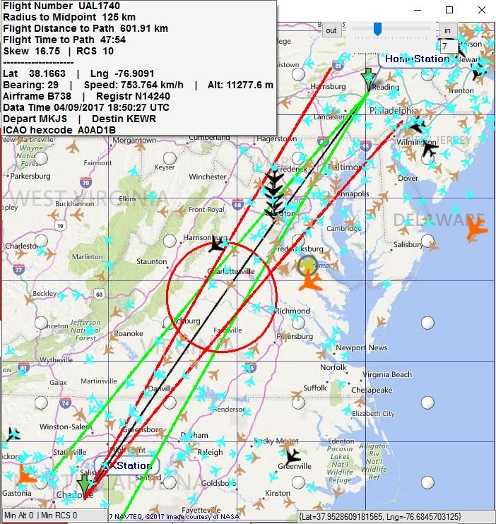
5 AircraftScatterSharp New Features Doppler Calculations (value and rate of change) Radar Cross Section modeling with estimated RCS for more than 100 aircraft Optionally, program will automatically assign RCS to selected aircraft using this model Adjustable lower limits for altitude and RCS below which planes will not be displayed Planes not meeting these limits will be removed from display Plane icon size and color indexed to RCS More extensive Manual Parameter Entry options including both static and dynamic modeling Rolling terrain elevation reporting

6 Aircraft Scatter is Bistatic Radar
7 Bistatic Radar Bistatic Radar Equation for Path Loss (db): L = 10 log((lambda**2)*s/(((rt**2)*(rr)**2))) 153 L = total loss (db) Rt = distance from transmitter to reflector (km) Rr = distance from receiver to reflector (km) Lambda = wavelength (m) S = radar cross section of aircraft (sq m) For lambda = 2M and Rt = Rr = 450km and S = 63 (B747): AS Path Loss = db Free Space -135; Troposcatter -241; EME -252 db
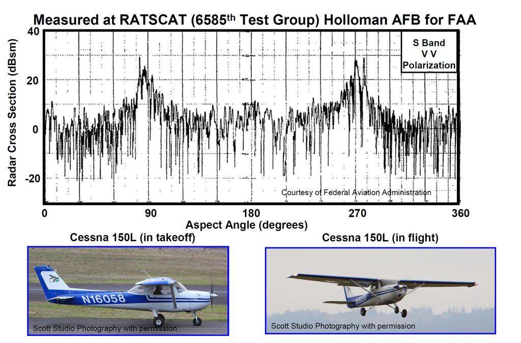
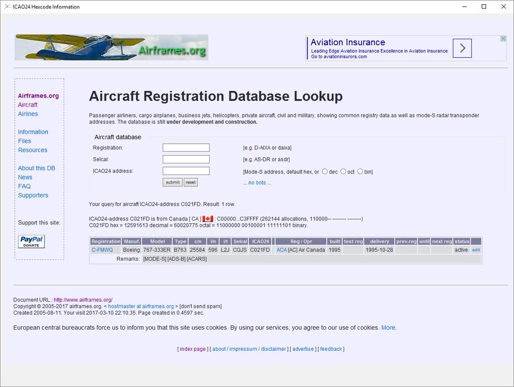
8 Radar Cross Section meters2 B-1 bomber 0.01 Radar Cross Sections Advanced tactical fighter Small single engine aircraft 1* Small fighter or 4-passenger jet (LearJet) 2*# Douglas DC-9 8# Boeing # Medium bomber or medium jet airliner 20 * Large bomber or large jet airliner 40 * Boeing # Jumbo jet 100* Bird 0.01 Man F-117 fighter B-2 bomber Automobile * Skolnik # ARRL UHF/Microwave Experime nter s Manual
9
10 Estimated Radar Cross Sections A B B B B A A B B777-VIP 67 B B B A B A A A B B B
11
12 Bistatic Radar Signal Loss is proportional to: Log((Frequency)2) = 20 (Log(Frequency)) db Log((Distance)4) = 40 Log(Distance) db Signal Loss is inversely proportional to: Log(Radar Cross Section) = 10 Log(RCS) db
13 Aircraft Scatter s Competition Troposcatter Frequency dependence of loss (db) 30 log(frequency) Distance dependence of loss ~9 db / 100km Meteor Scatter Loss (db) proportional to 30 Log(Frequency) Best at distances of km Aircraft scatter loss in db is proportional to: 20 Log(Frequency) and 40 Log(Distance) Which mode has best chance of success for a particular choice of frequency and distance?
14
15 LearJet RCS = 2 B747 RCS = * Log(2/63) = -15 db
16
17
18
19 Troposcatter s Achilles Heel
20 If we subtract 10 db of signal from Tropo for Take Off Angle of only 1 degree or add 20 db of signal to AS for Forward Scatter Enhancement, Balance shifts in favor of AS even for lower frequencies and shorter distances! But if the aircraft s RCS is lower than expected, then balance shifts in favor of troposcatter
21 Forward Scatter Enhancement Aircraft Scattering Angle
22
23
24 Aircraft Scattering Angle
25 Remember, AS Angle depends on the SUM of your skew angle PLUS your partner s skew angle Take-home message: Keep YOUR skew angle less than 3-5 degrees to keep FSE within 10 db of maximum possible value There is also a distance effect, but it is weaker than the skew-angle effect
26
27

28 FSE 144 MHz Beamwidth = * λ / radius FSE 10 GHz
29
30 Theory vs Reality - VK7MO 144 thru 1296 MHz 12/13 results were within 10 db Moncur R. Aircraft Enhancement Some Insights from Bistatic Radar Theory. CQ VHF Magazine Fall 2003.
31
32 What Do We Know So Far? Relative benefit of AS increases with frequency and with distance Must be along the interstation path or within about 3 degrees to get db Forward Scattering Enhancement Longer distances ( km or miles) will give greater FSE than shorter distances Path loss is high, generally above 200 db for 144 MHz and up, even with maximum Forward Scattering Enhancement The RCS is never precisely known for any particular case, so exact prediction of signal strengths is not possible. The calculations should be considered to be order of magnitude
33 Complications Antenna Pointing Doppler Shift
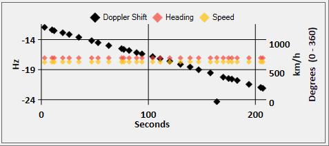
34 Is Pointing at the Aircraft Necessary? Consider both Elevation and Horizontal Skew compared with beamwidth of antenna array Elevation and Scattering Angle vs Distance for Aircraft Altitude 10,000 meters QSO Distance 200 km 400 km 600 km 800 km 1000 km Distance to Aircraft 100 km 200 km 300 km 400 km 500 km Elevation Scattering Angle * Maximum Forward Scattering Enhancement *
35 Complications: Doppler Shift Aircraft speeds km/h ( mph) Δf = (1/λ) * (VTx + VRx) λ = wavelength VTx = Plane s Velocity component along path from aircraft to Tx station VRx = Plane s Velocity component along path from aircraft to Rx station When plane is moving along the direct path between Tx and Rx stations, the two Doppler Velocities cancel out When plane is moving perpendicular to the direct path between the Tx and Rx stations, the two Doppler Velocities ADD This is another HUGE reason why it is GREAT when you can make use of a plane traveling along the direct path between your station and your QSO partner s station
36 Maximum Doppler Shift (Hz) Flight Perpendicular to Interstation Path (Single Station Component) MHz km/h
37 Maximum Doppler Shift Single Station Component
38 Doppler Shift (Hz) Flight Perpendicular to Interstation Path (Both Station Components) MHz km/h
39 Maximum Doppler Shift Both Station Components
40

41 16.48 Hz/second change in Doppler Shift is 247 Hz during a single 15 second ISCAT-A cycle Compare to Hz/ second for parallel flight path example just shown which gives change of 0.09 Hz over 15 second cycle


42 Doppler shift at 10 GHz for 1000 km/h = 9260 Hz * 2 = 18,530 Hz Change speed by 1% to 1010 km/h and Doppler changes by 1%, or 185 Hz!
43
44
45
46
47
48 Manual Calculations and Calculations on SQLite Database Aircraft Examples for RF Calculations, Max FSE,Tropo Angle, Doppler

49 Digital Modes and AS
50 Reasons to use Digital Modes for Aircraft Scatter Pull weak signals out of the noise Short chopped signal segments on upper bands Because it s cool
51 Complications to using Digital Modes with Aircraft Scatter Doppler shift Short chopped up signal blocks Short period to complete QSO if plane flying perpendicular to interstation path
52 Which Digital Mode to Use? Mode Spacing BW (Hz) Baud rate) Duration (s) S/N (db) JT4A JT9A JT65A QRA64A ISCAT-A * ISCAT-B * JT9E JT9F JT9G JT9H MSK /-8# MSK144 Sh & For Microwaves, ISCAT is preferred due to its tolerance for Doppler shifts, its 15 second periods and ability to cope with short bursts. MSK144 can t handle the Doppler shifts and JT65 is too slow and can t handle bursts. *with 30s average #for 70/500 ms burst &20 ms burst
53 Summary Try to use aircraft with minimal skew (< 3-5 degrees) to maximize FSE Try to use aircraft flying along interstation path to maximize QSO time, maximize FSE, minimize Doppler shift and its rate of change Use a program like Aircraft Scatter Sharp to track aircraft in real time Digital modes greatly increase your likelihood of completing QSOs (path losses greater than 200 db); ISCAT preferred for uwaves Whether or not you need to point at aircraft rather than at remote station depends on your beamwidth, skew angle, aircraft elevation Aircraft Scatter Sharp will track aircraft, allow you to estimate signal levels, compare with tropo signal levels, and see Doppler shift all in real time
54 Preferred Mode vs Band / Distance MHz km 300 or less T T/M M M 144 T A M/A M 222 T A A A# 432 T A A A# 903 T / A* A A A# 1296 and up T / A* A A A# T = TS, A=AS, M = MS. * TS will be favored over AS for high aircraft elevation angles # AS will be useful if the aircraft is above the horizon for both stations
55 Questions? Mach 9.6 (11,850 km/h)
56
 For 1296 MHz, if there is 29-49 db enhancement, then 8 db signal margin becomes 37-57 db signal")
57 Not just any Magic, but Physics Magic When the forward scattering angle is 180 degrees: We get constructive interference of the scattered radiation, called Diffractive Scattering which gives us Forward scatter enhancement = 4*Pi* A/(lambda**2) For 1296 MHz, if there is db enhancement, then 8 db signal margin becomes db signal margin
58
59 Something for Nothing? Beamwidth (in degrees) = (14.32 * lambda) / (radius) Frequency MHz G 5G 10G 1 meter 3 db beamwidth deg meters 3 db beamwidth deg meters 3 db beamwidth deg Radius
. Guy Fletcher, VK2KU also wrote an excellent theoretical paper on this subject 5
 Aircraft Scatter on VHF, UHF, and Microwave Frequencies: Increasing Understanding and Using Improved Tools to Increase Communications Distance and Maximize Success by Roger Rehr, W3SZ I. Basics and Review
Aircraft Scatter Propagation on 10 GHz using JT65C
 Aircraft Scatter Propagation on 10 GHz using JT65C Results of initial Tests over a 624 km Path By Rex Moncur VK7MO and David Smith VK3HZ This is an initial report of our first tests of 10 GHz propagation
Aircraft Scatter on 10 and 24 GHz using JT65c and ISCAT-A
 Aircraft Scatter on 10 and 24 GHz using JT65c and ISCAT-A By VK7MO and David Smith VK3HZ The authors have been using the digital modes JT65C and ISCAT-A to work aircraft scatter at distances of up to 842
The Analysis of the Airplane Flutter on Low Band Television Broadcasting Signal
 The Analysis of the Airplane Flutter on Low Band Television Broadcasting Signal A. Wonggeeratikun 1,2, S. Noppanakeepong 1, N. Leelaruji 1, N. Hemmakorn 1, and Y. Moriya 1 1 Faculty of Engineering and
Aircraft Scatter for the Microwave Enthusiast Roger Rehr, W3SZ 9/27/2013
 Aircraft Scatter for the Microwave Enthusiast Roger Rehr, W3SZ 9/27/2013 I. Basics. For our purposes, we will define aircraft scatter as the reflection of radio signals by airplanes. It is a specific example
255 km Aircraft Scatter QSO on 24 GHz
 255 km Aircraft Scatter QSO on 24 GHz First crossing of Bass Strait on 24 GHz By Rex Moncur VK7MO and David Smith VK3HZ On 13 March 2012, VK3HZ at Mt Liptrap near Wilson s Promontory in Victoria worked
Sw earth Dw Direct wave GRw Ground reflected wave Sw Surface wave
 WAVE PROPAGATION By Marcel H. De Canck, ON5AU Electromagnetic radio waves can propagate in three different ways between the transmitter and the receiver. 1- Ground waves 2- Troposphere waves 3- Sky waves
VHF/UHF Beyond FM Bob Witte KØNR Page 1
 VHF/UHF Beyond FM Technical Coordinator Colorado Section Page 1 Objective The objective of this presentation is to provide an introduction to operating on VHF/UHF, going beyond the usual FM / Repeater
Aircraft Scatter for the Microwave Enthusiast Roger Rehr, W3SZ 4/12/2014
 Aircraft Scatter for the Microwave Enthusiast Roger Rehr, W3SZ 4/12/2014 I. Basics. For our purposes, we will define aircraft scatter as the enhancement of radio signals by airplanes. It is a specific
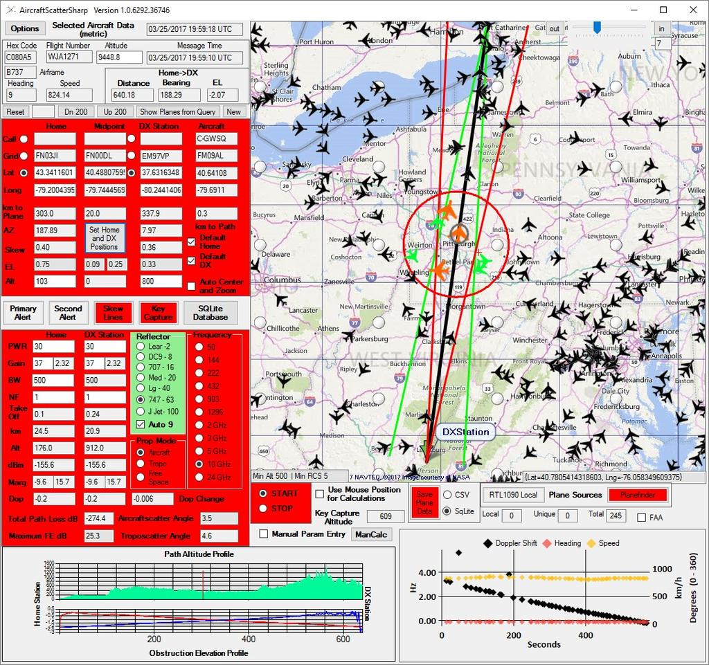
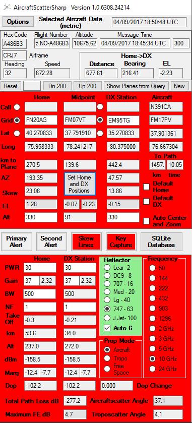
AircraftScatterSharp An Aircraft Scatter Assistance program for Datahounds --by Roger Rehr, W3SZ
 AircraftScatterSharp An Aircraft Scatter Assistance program for Datahounds --by Roger Rehr, W3SZ I wrote AircraftScatterSharp to assist those wanting to do aircraft scatter. This text highlights improvements
Annex 5. Determination of the interference field strength in the Land Mobile Service
 Annex 5 Determination of the interference field strength in the Land Mobile Service Annex 5, page 2 of 18 1 General 1.1 This calculation method is based on Recommendation ITU-R P.1546, taking into account
AircraftScatterSharp An Aircraft Scatter Assistance program for Datahounds --by Roger Rehr, W3SZ
 AircraftScatterSharp An Aircraft Scatter Assistance program for Datahounds --by Roger Rehr, W3SZ I wrote AircraftScatterSharp to assist those wanting to do aircraft scatter. This text highlights improvements
The Radio Channel. COS 463: Wireless Networks Lecture 14 Kyle Jamieson. [Parts adapted from I. Darwazeh, A. Goldsmith, T. Rappaport, P.
 The Radio Channel COS 463: Wireless Networks Lecture 14 Kyle Jamieson [Parts adapted from I. Darwazeh, A. Goldsmith, T. Rappaport, P. Steenkiste] Motivation The radio channel is what limits most radio
RECOMMENDATION ITU-R S.1340 *,**
 Rec. ITU-R S.1340 1 RECOMMENDATION ITU-R S.1340 *,** Sharing between feeder links the mobile-satellite service and the aeronautical radionavigation service in the Earth-to-space direction in the band 15.4-15.7
Experiments with Tropo-Scatter on 24 GHz
 Experiments with Tropo-Scatter on 24 GHz By Rex Moncur VK7MO and David Smith VK3HZ While it is possible to readily work up to around 200 km on 24 GHz with line of sight propagation between mountains, those
SODAR- sonic detecting and ranging
 Active Remote Sensing of the PBL Immersed vs. remote sensors Active vs. passive sensors RADAR- radio detection and ranging WSR-88D TDWR wind profiler SODAR- sonic detecting and ranging minisodar RASS RADAR
Introduction to Radar Systems. The Radar Equation. MIT Lincoln Laboratory _P_1Y.ppt ODonnell
 Introduction to Radar Systems The Radar Equation 361564_P_1Y.ppt Disclaimer of Endorsement and Liability The video courseware and accompanying viewgraphs presented on this server were prepared as an account
ATS 351 Lecture 9 Radar
 ATS 351 Lecture 9 Radar Radio Waves Electromagnetic Waves Consist of an electric field and a magnetic field Polarization: describes the orientation of the electric field. 1 Remote Sensing Passive vs Active
PART 1 RECOMMENDATION ITU-R P.1144 GUIDE TO THE APPLICATION OF THE PROPAGATION METHODS OF RADIOCOMMUNICATION STUDY GROUP 3
 Rec. ITU-R P.1144 1 PART 1 SECTION P-A: TEXTS OF GENERAL INTEREST Rec. ITU-R P.1144 RECOMMENDATION ITU-R P.1144 GUIDE TO THE APPLICATION OF THE PROPAGATION METHODS OF RADIOCOMMUNICATION STUDY GROUP 3 (1995)
EME with digital modes 144 MHz
 EME with digital modes 144 MHz SM4GGC Stig Larsson Ham radio licensed since 1973 Active on VHF/UHF 1973-1983 and from 2012- EME 1979-1983 and from 2012- Agenda Modes for digital EME WSJT 10 Weak Signal
Working Small Stations on 10 and 24 GHz EME with the help of WSJT
 Working Small Stations on 10 and 24 GHz EME with the help of WSJT Al Ward W5LUA October 19, 2013 Morehead State University Morehead, Kentucky The Bands Band Frequency Range Weak signal work in NA 33 cm
RECOMMENDATION ITU-R S.1341*
 Rec. ITU-R S.1341 1 RECOMMENDATION ITU-R S.1341* SHARING BETWEEN FEEDER LINKS FOR THE MOBILE-SATELLITE SERVICE AND THE AERONAUTICAL RADIONAVIGATION SERVICE IN THE SPACE-TO-EARTH DIRECTION IN THE BAND 15.4-15.7
Chapter 4 The RF Link
 Chapter 4 The RF Link The fundamental elements of the communications satellite Radio Frequency (RF) or free space link are introduced. Basic transmission parameters, such as Antenna gain, Beamwidth, Free-space
Acknowledgment. Process of Atmospheric Radiation. Atmospheric Transmittance. Microwaves used by Radar GMAT Principles of Remote Sensing
 GMAT 9600 Principles of Remote Sensing Week 4 Radar Background & Surface Interactions Acknowledgment Mike Chang Natural Resources Canada Process of Atmospheric Radiation Dr. Linlin Ge and Prof Bruce Forster
Detection of Targets in Noise and Pulse Compression Techniques
 Introduction to Radar Systems Detection of Targets in Noise and Pulse Compression Techniques Radar Course_1.ppt ODonnell 6-18-2 Disclaimer of Endorsement and Liability The video courseware and accompanying
Selected answers * Problem set 6
 Selected answers * Problem set 6 Wireless Communications, 2nd Ed 243/212 2 (the second one) GSM channel correlation across a burst A time slot in GSM has a length of 15625 bit-times (577 ) Of these, 825
ECE 476/ECE 501C/CS Wireless Communication Systems Winter Lecture 6: Fading
 ECE 476/ECE 501C/CS 513 - Wireless Communication Systems Winter 2003 Lecture 6: Fading Last lecture: Large scale propagation properties of wireless systems - slowly varying properties that depend primarily
DIGITAL BEAM-FORMING ANTENNA OPTIMIZATION FOR REFLECTOR BASED SPACE DEBRIS RADAR SYSTEM
 DIGITAL BEAM-FORMING ANTENNA OPTIMIZATION FOR REFLECTOR BASED SPACE DEBRIS RADAR SYSTEM A. Patyuchenko, M. Younis, G. Krieger German Aerospace Center (DLR), Microwaves and Radar Institute, Muenchner Strasse
Narrow- and wideband channels
 RADIO SYSTEMS ETIN15 Lecture no: 3 Narrow- and wideband channels Ove Edfors, Department of Electrical and Information technology Ove.Edfors@eit.lth.se 2012-03-19 Ove Edfors - ETIN15 1 Contents Short review
ESA Radar Remote Sensing Course ESA Radar Remote Sensing Course Radar, SAR, InSAR; a first introduction
 Radar, SAR, InSAR; a first introduction Ramon Hanssen Delft University of Technology The Netherlands r.f.hanssen@tudelft.nl Charles University in Prague Contents Radar background and fundamentals Imaging
Multipath fading effects on short range indoor RF links. White paper
 ALCIOM 5, Parvis Robert Schuman 92370 CHAVILLE - FRANCE Tel/Fax : 01 47 09 30 51 contact@alciom.com www.alciom.com Project : Multipath fading effects on short range indoor RF links DOCUMENT : REFERENCE
Extreme Grid QF km North of Broken Hill
 Extreme Grid QF09 100 km North of Broken Hill By Rex VK7MO and Dave VK3HZ A relatively easy ISCAT-B QSO over 753 km so the opportunity was taken to do an ISCAT-A test to see if we could get a better understanding
ECE 476/ECE 501C/CS Wireless Communication Systems Winter Lecture 6: Fading
 ECE 476/ECE 501C/CS 513 - Wireless Communication Systems Winter 2004 Lecture 6: Fading Last lecture: Large scale propagation properties of wireless systems - slowly varying properties that depend primarily
ECE 476/ECE 501C/CS Wireless Communication Systems Winter Lecture 6: Fading
 ECE 476/ECE 501C/CS 513 - Wireless Communication Systems Winter 2005 Lecture 6: Fading Last lecture: Large scale propagation properties of wireless systems - slowly varying properties that depend primarily
Radar Reprinted from "Waves in Motion", McGourty and Rideout, RET 2005
 Radar Reprinted from "Waves in Motion", McGourty and Rideout, RET 2005 What is Radar? RADAR (Radio Detection And Ranging) is a way to detect and study far off targets by transmitting a radio pulse in the
Terrain Reflection and Diffraction, Part One
 Terrain Reflection and Diffraction, Part One 1 UHF and VHF paths near the ground 2 Propagation over a plane Earth 3 Fresnel zones Levis, Johnson, Teixeira (ESL/OSU) Radiowave Propagation August 17, 2018
Radio Propagation Fundamentals
 Radio Propagation Fundamentals Concept of Electromagnetic Wave Propagation Mechanisms Modes of Propagation Propagation Models Path Profiles Link Budget Fading Channels Electromagnetic (EM) Waves EM Wave
A Bistatic HF Radar for Current Mapping and Robust Ship Tracking
 A Bistatic HF Radar for Current Mapping and Robust Ship Tracking Dennis Trizna Imaging Science Research, Inc. V. 703-801-1417 dennis @ isr-sensing.com www.isr-sensing.com Objective: Develop methods for
Dr. John S. Seybold. November 9, IEEE Melbourne COM/SP AP/MTT Chapters
 Antennas Dr. John S. Seybold November 9, 004 IEEE Melbourne COM/SP AP/MTT Chapters Introduction The antenna is the air interface of a communication system An antenna is an electrical conductor or system
Fundamental Concepts of Radar
 Fundamental Concepts of Radar Dr Clive Alabaster & Dr Evan Hughes White Horse Radar Limited Contents Basic concepts of radar Detection Performance Target parameters measurable by a radar Primary/secondary
Revision of Lecture One
 Revision of Lecture One System blocks and basic concepts Multiple access, MIMO, space-time Transceiver Wireless Channel Signal/System: Bandpass (Passband) Baseband Baseband complex envelope Linear system:
Study of Factors which affect the Calculation of Co- Channel Interference in a Radio Link
 International Journal of Electronic and Electrical Engineering. ISSN 0974-2174 Volume 8, Number 2 (2015), pp. 103-111 International Research Publication House http://www.irphouse.com Study of Factors which
Modern radio techniques
 Modern radio techniques for probing the ionosphere Receiver, radar, advanced ionospheric sounder, and related techniques Cesidio Bianchi INGV - Roma Italy Ionospheric properties related to radio waves
Radar level measurement - The users guide
 Radar level measurement The user's guide Radar level measurement - The users guide Peter Devine written by Peter Devine additional information Karl Grießbaum type setting and layout Liz Moakes final drawings
VK7MO 10 GHz EME Grid Square Tour across Australia
 VK7MO 10 GHz EME Grid Square Tour across Australia From mid November to mid December VK7MO took his portable 10 GHz system (Fig 1 and Fig 2) across Australia and activated some 25 grid squares (Fig 3)
RADAR EQUATIONS 4-0.1
 RADAR EQUATIONS Field Intensity and Power Density... 4-1 Power Density... 4- One-Way Radar Equation / RF Propagation... 4-3 Two-Way Radar Equation (Monostatic)... 4-4 Alternate Two-Way Radar Equation...
Colubris Networks. Antenna Guide
 Colubris Networks Antenna Guide Creation Date: February 10, 2006 Revision: 1.0 Table of Contents 1. INTRODUCTION... 3 2. ANTENNA TYPES... 3 2.1. OMNI-DIRECTIONAL ANTENNA... 3 2.2. DIRECTIONAL ANTENNA...
FORMATION FLYING PICOSAT SWARMS FOR FORMING EXTREMELY LARGE APERTURES
 FORMATION FLYING PICOSAT SWARMS FOR FORMING EXTREMELY LARGE APERTURES Presented at the ESA/ESTEC Workshop on Innovative System Concepts February 21, 2006 Ivan Bekey President, Bekey Designs, Inc. 4624
Narrow- and wideband channels
 RADIO SYSTEMS ETIN15 Lecture no: 3 Narrow- and wideband channels Ove Edfors, Department of Electrical and Information technology Ove.Edfors@eit.lth.se 27 March 2017 1 Contents Short review NARROW-BAND
Lecture Topics. Doppler CW Radar System, FM-CW Radar System, Moving Target Indication Radar System, and Pulsed Doppler Radar System
 Lecture Topics Doppler CW Radar System, FM-CW Radar System, Moving Target Indication Radar System, and Pulsed Doppler Radar System 1 Remember that: An EM wave is a function of both space and time e.g.
1. Transverse Waves: the particles in the medium move perpendicular to the direction of the wave motion
 Mechanical Waves Represents the periodic motion of matter e.g. water, sound Energy can be transferred from one point to another by waves Waves are cyclical in nature and display simple harmonic motion
Multi Band Passive Forward Scatter Radar
 Multi Band Passive Forward Scatter Radar S. Hristov, A. De Luca, M. Gashinova, A. Stove, M. Cherniakov EESE, University of Birmingham Birmingham, B15 2TT, UK m.cherniakov@bham.ac.uk Outline Multi-Band
Project = An Adventure : Wireless Networks. Lecture 4: More Physical Layer. What is an Antenna? Outline. Page 1
 Project = An Adventure 18-759: Wireless Networks Checkpoint 2 Checkpoint 1 Lecture 4: More Physical Layer You are here Done! Peter Steenkiste Departments of Computer Science and Electrical and Computer
Noise and Propagation mechanisms
 2 Noise and Propagation mechanisms Noise Johnson-Nyquist noise Physical review 1928 V rms2 = 4kTBR k : Bolzmann s constant T : absolute temperature B : bandwidth R : Resistance P=4kTB 1 1 Why is this a
August, Antennas 101: A Course in RF Basics
 August, 2012 Antennas 101: A Course in RF Basics Antenna Basics Agenda: In today s training, we will go over a brief summary of the following topics at a basic level: Electromagnetic Waves Frequency and
Chapter 15: Radio-Wave Propagation
 Chapter 15: Radio-Wave Propagation MULTIPLE CHOICE 1. Radio waves were first predicted mathematically by: a. Armstrong c. Maxwell b. Hertz d. Marconi 2. Radio waves were first demonstrated experimentally
Radio Propagation - VHF and higher
 Radio Propagation - VHF and higher (Without the Mathematics) Presented by Dr John Worsnop G4BAO RSGB Propagation Studies Committee RadCom GHz bands Columnist With a little help from http://www.mike-willis.com/tutorial/propagation.html
UNIT Derive the fundamental equation for free space propagation?
 UNIT 8 1. Derive the fundamental equation for free space propagation? Fundamental Equation for Free Space Propagation Consider the transmitter power (P t ) radiated uniformly in all the directions (isotropic),
Elevation and Pseudo-Brewster Angle Formation of Ground- Mounted Vertical Antennas
 Robert J. Zavrel, Jr., W7SX PO Box 9, Elmira, OR 97437; w7sx@arrl.net Elevation and Pseudo-Brewster Angle Formation of Ground- Mounted Vertical Antennas The formation of the elevation pattern of ground
Introduction to Radar Systems. Radar Antennas. MIT Lincoln Laboratory. Radar Antennas - 1 PRH 6/18/02
 Introduction to Radar Systems Radar Antennas Radar Antennas - 1 Disclaimer of Endorsement and Liability The video courseware and accompanying viewgraphs presented on this server were prepared as an account
Characteristics of HF Coastal Radars
 Function Characteristics System 1 Maximum operational (measurement) range** Characteristics of HF Coastal Radars 5 MHz Long-range oceanographic 160-220 km average during (daytime)* System 2 System 3 System
Naval Surveillance Multi-beam Active Phased Array Radar (MAARS)
") Naval Surveillance Multi-beam Active Phased Array Radar (MAARS) MAARS MAARS purpose: MAARS is multimode C-band acquisition radar for surveillance and weapon assignment. It perform automatic detection,
Naval Surveillance Multi-beam Active Phased Array Radar (MAARS) MAARS MAARS purpose: MAARS is multimode C-band acquisition radar for surveillance and weapon assignment. It perform automatic detection,
Information on the Evaluation of VHF and UHF Terrestrial Cross-Border Frequency Coordination Requests
 Issue 1 May 2013 Spectrum Management and Telecommunications Technical Bulletin Information on the Evaluation of VHF and UHF Terrestrial Cross-Border Frequency Coordination Requests Aussi disponible en
Evolution of the WSJT Digital Modes
 Evolution of the WSJT Digital Modes Mike Hasselbeck WB2FKO New Mexico TechFest 25 February 2017 WSJT: A software package for digital radio communication Weak Signal communication by Professor Joe Taylor
Yagi Antenna Tutorial. Copyright K7JLT 1
 Yagi Antenna Tutorial Copyright K7JLT Yagi: The Man & Developments In the 920 s two Japanese electrical engineers, Hidetsugu Yagi and Shintaro Uda at Tohoku University in Sendai Japan, investigated ways
Link Budget Calculation
 Link Budget Calculation Training materials for wireless trainers This 60 minute talk is about estimating wireless link performance by using link budget calculations. It also introduces the Radio Mobile
Amateur Radio License. Propagation and Antennas
 Amateur Radio License Propagation and Antennas Todays Topics Propagation Antennas Propagation Modes Ground wave Low HF and below, ground acts as waveguide Line-of-Sight (LOS) VHF and above, radio waves
Earth Station Coordination
 1 Overview Radio spectrum is a scarce resource that should be used as efficiently as possible. This can be achieved by re-using the spectrum many times - having many systems operate simultaneously on the
Revision of Lecture One
 Revision of Lecture One System block Transceiver Wireless Channel Signal / System: Bandpass (Passband) Baseband Baseband complex envelope Linear system: complex (baseband) channel impulse response Channel:
Rec. ITU-R P RECOMMENDATION ITU-R P *
 Rec. ITU-R P.682-1 1 RECOMMENDATION ITU-R P.682-1 * PROPAGATION DATA REQUIRED FOR THE DESIGN OF EARTH-SPACE AERONAUTICAL MOBILE TELECOMMUNICATION SYSTEMS (Question ITU-R 207/3) Rec. 682-1 (1990-1992) The
Range Considerations for RF Networks
 TI Technology Days 2010 Range Considerations for RF Networks Richard Wallace Abstract The antenna can be one of the most daunting components of wireless designs. Most information available relates to large
1 PERFORMANCE COMPARISION BETWEEN HIGHER-ORDER AND RWG BASIS FUNCTIONS
 1 PERFORMANCE COMPARISION BETWEEN HIGHER-ORDER AND RWG BASIS FUNCTIONS Two monopoles are mounted on a PEC cylinder oriented along the z axis. The length and radius of the cylinder are 5. m and 1. m, respectively.
Ch. III - Limits of single polarity antennas in the VHF and UHF bands
 Ch. III - Limits of single polarity antennas in the VHF and UHF bands Ch. I 2014 QSB origins 2 m Faraday Ch. II 2016 Extension of Excel sheet to VHF and UHF bands From studies by Giorgio Marchi, IK1UWL
Basic Radio Physics. Developed by Sebastian Buettrich. ItrainOnline MMTK 1
 Basic Radio Physics Developed by Sebastian Buettrich 1 Goals Understand radiation/waves used in wireless networking. Understand some basic principles of their behaviour. Apply this understanding to real
OCEAN SURFACE ROUGHNESS REFLECTOMETRY WITH GPS MULTISTATIC RADAR FROM HIGH-ALTITUDE AIRCRAFT
 OCEAN SURFACE ROUGHNESS REFLECTOMETRY WITH GPS MULTISTATIC RADAR FROM HIGH-ALTITUDE AIRCRAFT VALERY U. ZAVOROTNY 1, DENNIS M. AKOS 2, HANNA MUNTZING 3 1 NOAA/Earth System Research Laboratory/ Physical
Active Cancellation Algorithm for Radar Cross Section Reduction
 International Journal of Computational Engineering Research Vol, 3 Issue, 7 Active Cancellation Algorithm for Radar Cross Section Reduction Isam Abdelnabi Osman, Mustafa Osman Ali Abdelrasoul Jabar Alzebaidi
Investigation of Board-Mounted Omni- Directional Antennas for WLAN- Applications
 Investigation of Board-Mounted Omni- Directional Antennas for WLAN- Applications Luis Quineche ISE Master Student EEE: Communications Engineering Index Description of Problem Thesis Task Background Theory
This article reports on
 Millimeter-Wave FMCW Radar Transceiver/Antenna for Automotive Applications A summary of the design and performance of a 77 GHz radar unit David D. Li, Sam C. Luo and Robert M. Knox Epsilon Lambda Electronics
Amateur Microwave Communications. Ray Perrin VE3FN, VY0AAA April 2010
 Amateur Microwave Communications Ray Perrin VE3FN, VY0AAA April 2010 Introduction Microwaves are the frequencies above 1000 MHz More than 99% of the radio amateur frequency allocation is in the microwave
Characteristics and protection criteria for radars operating in the aeronautical radionavigation service in the frequency band
 Recommendation ITU-R M.2008 (03/2012) Characteristics and protection criteria for radars operating in the aeronautical radionavigation service in the frequency band 13.25-13.40 GHz M Series Mobile, radiodetermination,
RECOMMENDATION ITU-R P Guide to the application of the propagation methods of Radiocommunication Study Group 3
 Rec. ITU-R P.1144-2 1 RECOMMENDATION ITU-R P.1144-2 Guide to the application of the propagation methods of Radiocommunication Study Group 3 (1995-1999-2001) The ITU Radiocommunication Assembly, considering
BYU SAR: A LOW COST COMPACT SYNTHETIC APERTURE RADAR
 BYU SAR: A LOW COST COMPACT SYNTHETIC APERTURE RADAR David G. Long, Bryan Jarrett, David V. Arnold, Jorge Cano ABSTRACT Synthetic Aperture Radar (SAR) systems are typically very complex and expensive.
New functions and changes summary
 New functions and changes summary A comparison of PitLab & Zbig FPV System versions 2.50 and 2.40 Table of Contents New features...2 OSD and autopilot...2 Navigation modes...2 Routes...2 Takeoff...2 Automatic
The LoRa Protocol. Overview. Interference Immunity. Technical Brief AN205 Rev A0
 Technical Brief AN205 Rev A0 The LoRa Protocol By John Sonnenberg Raveon Technologies Corp Overview The LoRa (short for Long Range) modulation scheme is a modulation technique combined with a data encoding
Composite Messenger Antenna Array 8 (CMAA8)
") 15 db, 5.9 7.4 GHz, Seven-Panel Array Plus Up-look Antenna Family The most important thing we build is trust. Applications Long Distance A/V Mobile Links Airborne Surveillance Links Electronic News Gathering
15 db, 5.9 7.4 GHz, Seven-Panel Array Plus Up-look Antenna Family The most important thing we build is trust. Applications Long Distance A/V Mobile Links Airborne Surveillance Links Electronic News Gathering
Vehicle Networks. Wireless communication basics. Univ.-Prof. Dr. Thomas Strang, Dipl.-Inform. Matthias Röckl
 Vehicle Networks Wireless communication basics Univ.-Prof. Dr. Thomas Strang, Dipl.-Inform. Matthias Röckl Outline Wireless Signal Propagation Electro-magnetic waves Signal impairments Attenuation Distortion
Ham Radio Training. Level 1 Technician Level. Presented by Richard Bosch KJ4WBB
 Ham Radio Training Level 1 Technician Level Presented by Richard Bosch KJ4WBB In this chapter, you ll learn about: What is a radio signal The characteristics of radio signals How modulation adds information
RECOMMENDATION ITU-R SA (Question ITU-R 210/7)
") Rec. ITU-R SA.1016 1 RECOMMENDATION ITU-R SA.1016 SHARING CONSIDERATIONS RELATING TO DEEP-SPACE RESEARCH (Question ITU-R 210/7) Rec. ITU-R SA.1016 (1994) The ITU Radiocommunication Assembly, considering
Rec. ITU-R SA.1016 1 RECOMMENDATION ITU-R SA.1016 SHARING CONSIDERATIONS RELATING TO DEEP-SPACE RESEARCH (Question ITU-R 210/7) Rec. ITU-R SA.1016 (1994) The ITU Radiocommunication Assembly, considering
Propagation mechanisms
 RADIO SYSTEMS ETIN15 Lecture no: 2 Propagation mechanisms Ove Edfors, Department of Electrical and Information Technology Ove.Edfors@eit.lth.se Contents Short on db calculations Basics about antennas Propagation
ECE 476/ECE 501C/CS Wireless Communication Systems Winter Lecture 3: Cellular Fundamentals
 ECE 476/ECE 501C/CS 513 - Wireless Communication Systems Winter 2004 Lecture 3: Cellular Fundamentals Chapter 3 - The Cellular Concept - System Design Fundamentals I. Introduction Goals of a Cellular System
What is VOACAP Trying to Tell Me?
 What is VOACAP Trying to Tell Me? A Presentation to The Yankee Clipper Contest Club Feb. 1, 2003 Milford, CT by Dean Straw, N6BV Senior Assistant Technical Editor, ARRL VOACAP VOACAP has been under development
RCS Computation, Reduction and Stealth Design
 RCS Computation, Reduction and Stealth Design Micah Li PhD EM Application Engineer Flomerics U.K. micah.li@flomerics.co.uk Agenda Introduction Background of TLM (MICROSTRIPES) Numerically predicting the
Subsystems of Radar and Signal Processing and ST Radar
 Advance in Electronic and Electric Engineering. ISSN 2231-1297, Volume 3, Number 5 (2013), pp. 531-538 Research India Publications http://www.ripublication.com/aeee.htm Subsystems of Radar and Signal Processing
Radar observables: Target range Target angles (azimuth & elevation) Target size (radar cross section) Target speed (Doppler) Target features (imaging)
 Target size (radar cross section) Target speed (Doppler) Target features (imaging)") Fundamentals of Radar Prof. N.V.S.N. Sarma Outline 1. Definition and Principles of radar 2. Radar Frequencies 3. Radar Types and Applications 4. Radar Operation 5. Radar modes What What is is Radar? Radar?
Fundamentals of Radar Prof. N.V.S.N. Sarma Outline 1. Definition and Principles of radar 2. Radar Frequencies 3. Radar Types and Applications 4. Radar Operation 5. Radar modes What What is is Radar? Radar?
IBIS range. GeoRadar Division. GeoRadar Division. Static and Dynamic Monitoring of Civil Engineering Structures by Microwave Interferometry
 Static and Dynamic Monitoring of Civil Engineering Structures by Microwave Interferometry Garry Spencer and Mark Bell 1 PRODUCTS IBIS range APPLICATIONS IBIS - FL LANDSLIDE & DAM MONITORING IBIS - FM SLOPE
Fundamentals Of Commercial Doppler Systems
 Fundamentals Of Commercial Doppler Systems Speed, Motion and Distance Measurements I. Introduction MDT manufactures a large variety of microwave oscillators, transceivers, and other components for the
Spectrum & Power Measurements Using the E6474A Wireless Network Optimization Platform Application Note By Richard Komar
 Spectrum & Power Measurements Using the E6474A Wireless Network Optimization Platform Application Note By Richard Komar Contents Introduction...1 Band Clearing...2 Using the spectrum analyzer for band
Channel Modeling and Characteristics
 Channel Modeling and Characteristics Dr. Farid Farahmand Updated:10/15/13, 10/20/14 Line-of-Sight Transmission (LOS) Impairments The received signal is different from the transmitted signal due to transmission
Lecture Note on Wireless Communication Engineering I
 Lecture Note on Wireless Communication Engineering I Prof. Kiyomichi Araki Department of Electrical & Electronics Tokyo Institute of Technology South III Bld. Room No. 912 TEL/FAX: 03-5734-3495 E-mail:
ANTENNA INTRODUCTION / BASICS
 Rules of Thumb: 1. The Gain of an antenna with losses is given by: G 0A 8 Where 0 ' Efficiency A ' Physical aperture area 8 ' wavelength ANTENNA INTRODUCTION / BASICS another is:. Gain of rectangular X-Band