RESEARCH COUNCIL ON STRUCTURAL CONNECTIONS (RCSC) MINUTES of SPECIFICATION COMMITTEE A.1 6 June 2013, 8:00AM, Cincinnati, OH
|
|
|
- Britton Waters
- 5 years ago
- Views:
Transcription
1 RESEARCH COUNCIL ON STRUCTURAL CONNECTIONS (RCSC) MINUTES of SPECIFICATION COMMITTEE A.1 6 June 2013, 8:00AM, Cincinnati, OH Members T. Anderson, P. Birkemoe, D. Bogarty, D. Bornstein, R. Brown, C. Curven, Present: D. Ferrell, P. Fortney, B. Germuga, J. Gialamas, J. Greenslade, A. Harrold, (37) T. Helwig, C. Kanapicki, P. Kasper, L. Kruth, C. Larson, B. Lindley, K. Lohr, C. Mayes, C. McGee, K. Menke, G. Miazga, G. Mitchell, H. Mitchell, G. Rassati, T. Schlafly, G. Schroeder, R. Shaw, V. Shneur, L. Shoemaker, J. Swanson, W. Thornton, R. Tide, F. Vissat, A. Wong, J. Yura Members A. Astaneh-Asi, R. Baxter, B. Cornelissen, N. Deal, D. Droddy, J. Fisher, Absent: K. Frank, R. Gibble, M. Gilmor, C. Hundley, J. Kennedy, N. McMillan, J. Mehta, (15) T.Tarpy, C. Wilson Guest: D. Auer-Collis, R. Babik, G. Byrne, R. Connor, C. Carter, G. DePhillis, P. Dusicka (19) M. Eatherton, M. Friel, B. Goldsmith, P. Herbst, E. Jefferson, J. McGormley, J. Ocel, B. Porter, R. Shanley, J. Soma, T. Ude, W. Wloszek AGENDA ITEM 1.0 Chairman s Remarks: (Harrold) Specification Committee Chairman Harrold introduced hosts Jim Swanson & Gian Rassati from the University of Cincinnati. Specification Committee A.1 meeting will conclude around 12:00 Noon. Task Groups can meet after lunch; 2:00pm testing of super-high-strength bolts at high bay lab; 4:00pm tour of the Cincinnati Museum Center (old train station). Council Roster was circulated for verification and update of address, phone and fax numbers and any additional comments as required. Presently, there are fifty-two members on Specification Committee A.1; guests were also asked to sign-in. Introduction of attendees. Discussions and voting shall be limited to Specification Committee A.1 members only. Discussions shall be limited only to agenda items listed. New specification to be issued by end of 2014; therefore ballot items need to be resolved by 2014 annual meeting. ITEM 2.0 Approval of Minutes of the June 2012 Meeting: (Harrold) Vissat noted that Item 5.4 was incorrectly written in the 2012 meeting minutes. The corrected editorial changes are as follows: Pretension (verb). The act of tightening a fastener assembly such that the minimum specified tensile force exists. to a specific level of tension or higher. Pretension (noun). A level of minimum specified tensile force remaining tension achieved in a fastener assembly through after its installation, as required for pretensioned and slip-critical joints. No additional comments, corrections and discussions took place; therefore Harrold concluded an approval of the minutes as noted. 1
2 ITEM 3.0 Approval of Agenda: (Harrold) Changes to agenda are as follows: Requested by Brown to add Item 6.4 to Discussion of Proposed Specification Changes section as related to ASTM F959 revision. Requested by Shaw to add Item 9.2 to New Business section regarding XTB bolts. Requested by Mayes to add Item 9.3 to New Business section regarding Snug Tight definition. Requested by Shaw to add Item 9.4 to New Business section regarding large holes and large bolts. No additional agenda items were suggested; therefore Harrold concluded that the proposed agenda, with noted changes incorporated, is approved as modifed. ITEM 4.0 Membership: (Harrold) Roster was circulated for sign-in and updating of information. If guests are interested in joining Specification Committee A.1, they were asked to see Harrold during the break, after the meeting or send an to Harrold. Geoff Kulak was approved by exec committee as a life member and has resigned from Specification Committee A.1. After the meeting, Rachel Shanley, Jim Soma and Peter Dusicka sent Harrold requesting Specification Committee A.1 membership. ITEM 5.0 Resolution of Ballot Results (Affirmative/Negative/Abstain): (Harrold) 5.1 S Sections 8.2, 8.2.1, and Pre-installation Verification Testing Language (Curven): ( Ballot Item 1 summary: 61/5/2 Affirmative /Negative/Abstention). The ballot had 5 negatives (Ferrell, McGormley, G. Mitchell, H. Mitchell, and Tide). Addressing the first negative, Curven moved and Shaw seconded to find Ferrell s negative vote for the balloted proposed change to be non-persuasive. Discussion followed (Ferrell, McGormley, Carter, Harrold, Curven, Schroder, H. Mitchell, G. Mitchell, Yura). All five negative votes had similar comments; repeating the pre-installation verification in the definition of each installation method is not necessary. Incorrect references need to be corrected; considered editorial in nature. Harrold requested a vote for the motion to find Ferrell s negative vote non-persuasive, with results as follows: 2 for the vote to be non-persuasive 19 against the vote to be non-persuasive 11 abstained A task group was created to modify the language. ACTION ITEM (A.1) (S11-038): The as-balloted item with proposed changes to the Specification was considered and defeated for inclusion into the next revision of the Specification. A task group composed of Curven (chair), Carter, G. Mitchell, Shaw, and Ude will review and revise the as presented proposal language. 5.2 S Table 2.1 Delete Zn/Al coating from F1852 and F2280 assemblies (Schlafly): ( Ballot Item 2 summary: 61/3/4 Affirmative/Negative/Abstention). The ballot had three negatives (Kasper, Lohr, Mayes), all generally had similar issues; successful usage worldwide of Zn/Al coatings on TC bolts without ASTM language explicitly allowing the coating. Discussion followed (Harrold, Lohr, Larsen, Schafly, Curven, Kasper, Mayes, Greenslade, McGormley, Shaw). With several new coatings being introduced to the market, suggest referencing ASTM approved coatings list verses constantly updating RCSC Table 2.1. If the manufacture or user introduces a secondary process change (coating or lubrication) to the assembly, then the entire assembly needs to be tested and re-certified. Tide moved and Shneur seconded to find all three negative votes for the balloted proposed change to be non-persuasive. Harrold requested a vote for the motion with the understanding that a Task Group would add Commentary language; result of the vote was as follows: 2
3 24 for the votes to be non-persuasive 5 against the votes to be non-persuasive 6 abstained ACTION ITEM (A.1) (S12-039): The as-balloted item with proposed changes to the Specification was considered and accepted for inclusion into the next revision of the Specification with the understanding that a Task Group will draft Commentary language that discusses ramifications of using non-astm approved coatings on ASTM F1852 & F2280 TC bolt assemblies. The Task Group is composed of Schlafly (chair), Auer-Collis, Babik, Gialamas, Kasper, Lohr, Mayes, G. Mitchell and Soma. 5.3 S Section 5.4 Slip Critical Equations (Schlafly): ( Ballot Item 3 summary: 48/3/17 Affirmative/Negative/Abstention). The ballot had eight affirmative votes with comments. Schlafly considered no actions/changes required from Baxton, Eatherton and Helwig comments. Changes as follows from Birkemoe, Chen, Connor, H. Mitchell and Schlafly were considered and accepted as editorial: in new Commentary language, include the words reliability index, before the word beta, ; in Section 5.4, third paragraph, replace The available slip resistance for the limit state.with The nominal slip resistance per bolt for the limit state ; remove Item (4) from Section 1.4; delete Commentary paragraph that begins with Because of the greater. ; change Commentary Item (2), second sentence should be to are ; change Commentary Item (3), first sentence can be to is. The ballot had three negatives (Tide, Yura & Wong). Comments from Tide were editorial in nature; poor grammar and poor specification writing. Schlafly will include in the first sentence of Section 5.4 references to Sections 5.1, 5.2 and 5.3 for bearing-type connection limit states. With the understanding that editorial comments from Tide would be considered and accepted, Tide withdrew his negative vote. Yura suggested that in Section 5.4, reference to ASD and Canadian LSD be removed; Schlafly agreed with removing the Canadian reference, but not the LRFD & ASD duel system callout (LRFD ( ) & ASD ( ) is used throughout the Specification to align with AISC; see Ballot Item S11-033). Schlafly previously agreed with deleting Commentary paragraph that begins with Because of the greater., change Commentary Item (2), second sentence should be to are and change Commentary Item (3), first sentence can be to is. Schlafly agreed to include at the end of the second to last sentence of the first paragraph in the Commentary for specimens tightened using the calibrated wrench method and remove from the first sentence of the seventh paragraph approximately in the single value of the slip probability factor D u. With the additions and deletions discussed and agreed upon, Yura withdrew his negative vote. Wong provided no explanation for the negative and per the bylaws of the Council that negative vote was ignored. ACTION ITEM (A.1) (S12-042): The as-balloted item with proposed changes to the Specification were considered and accepted for inclusion into the next revision of the Specification with the understanding that several editorial comments from affirmative and negative votes be included. 5.4 S Section 8.1 Commentary TC bolts in Snug Tight joints (Schlafly): ( Ballot Item 4 summary: 66/1/1 Affirmative/Negative/Abstention). Ballot language was written to eliminate economical or esthetical favoritism to either condition of having the splines of TC bolts twisted off or left in place. The ballot had five affirmative votes with comments. Schlafly considered no actions/changes required from Astaneh, Hay and Vissat comments. Chen comment not related to the ballot proposal, but considered new business if Chen desires to pursue. McGormley suggested that the word twisted-off be replaced with the word removed. A twisted-off condition would indicate that the bolt assembly was fully pre-tensioned. Discussion followed (McGormley, G. Mitchell, H. Mitchell, Mayes, Schroder, Ferrell, Kruth). Schlafly will consider the revised wording. The ballot had one negative (Frank). Further discussion followed (Yura, Shoemaker, Harrold, Fortney, Shneur, Larsen, Shaw, Ferrell). If so 3
4 required by the engineer that a snug tightened joint not have the splines removed, Commentary language should direct that required information be included on the Design Drawing or in the Specification. There is no maximum preload required for a snug tightened joint. Schlafly moved and Ferrell seconded to find the negative vote for the balloted proposed change to be non-persuasive. Harrold requested a vote for the motion as follows: 33 for the vote to be non-persuasive 0 against the vote to be non-persuasive 3 abstained ACTION ITEM (A.1) (S12-043): The as-balloted item with proposed changes to the Specification was considered and accepted for inclusion into the next revision of the Specification. 5.5 S Section 5.1 Fillers (Schlafly): ( Ballot Item 5 summary: 57/2/9 Affirmative/Negative/Abstention). The ballot had eight affirmative votes with comments. Schlafly considered no actions/changes required from Birkemoe comment; changes from Chen, Ricles & Tide were considered and accepted as editorial; Conner comment to change they to the connection was accepted; Frank comment not related to the ballot proposal, but considered new business if Frank desires to pursue; Shaw comment that (4) be split into (4) and (5) was considered and accepted as editorial; Shoemaker comment regarding clarification to the number of tests using 24-bolt connections was considered and accepted as editorial. The ballot had two negatives (Baxter, Dusicka). Further discussion followed (Schlafly, Yura, Shaw, Harrold). Baxter negative vote does not have data to support including alternate design fasteners (TC bolts) in (4). Schlafly moved and Shaw seconded to find Baxter s negative vote for the balloted proposed change to be non-persuasive. Harrold requested a vote for the motion as follows: 25 for the vote to be non-persuasive 0 against the vote to be non-persuasive 12 abstained Dusicka negative vote basis needs further work with supporting data, therefore Schafly requested Dusicka to withdraw his negative vote and consider negative comment as New Business; Dusicka agreed to withdraw his negative vote. ACTION ITEM (A.1) (S12-044): The as-balloted item with proposed changes to the Specification was considered and accepted for inclusion into the next revision of the Specification with the understanding that several affirmative votes with comments would be included. 5.6 S Sections 8.2.3, 9.2.1, 9.2.2, Inspection Process (Curven): ( Ballot Item 6 summary: 52/10/6 Affirmative/Negative/Abstention). The ballot had 10 negatives (Ferrell, Hay, Helwig, Lohr, Mayes, McGormley, G. Mitchell, H. Mitchell, Tide and Ude). Discussion followed (Curven, Harrold, Shaw). Since this ballot item is similar to Ballot Item 1 (S11-038), it was suggested that the 10 negative votes be found persuasive and the same Task Group for Ballot Item 1 also address Ballot Item 6. ACTION ITEM (A.1) (S12-045): The as-balloted item with proposed changes to the Specification was considered and defeated for inclusion into the next revision of the Specification. A task group composed of Curven (chair), Carter, G. Mitchell, Shaw, and Ude will review and revise the as presented proposal language. 5.7 S Section 3.3 Hole Definitions (Kruth): ( Ballot Item 7 summary: 63/3/2 Affirmative/Negative/Abstention). The ballot had three negatives (Curven, Frank, Helwig). Modifications (5/10/13) to the as-balloted items, shown as either double strikethrough or double underline, were made to satisfy Frank and Helwig negatives. These modifications in 4
5 essence find Frank and Helwig negative votes persuasive. Kurth moved and Shneur seconded to find Curven negative vote for the balloted proposed change to be non-persuasive. Discussion followed (McGormley, Harrold, Kruth, Ferrell, Shneur, H. Mitchell, Fortney, Helwig). Since changes have been made to the as-balloted items, these changes will need to be reballoted. The re-write to Section Commentary needs to address end connection rotation effects on beam/girder members that are not laterally or torsionally restrained. The EOR needs to define not using short slotted holes; use permitted unless otherwise defined as not acceptable. The ballot item was returned to the task group for further discussion regarding the proposal. ACTION ITEM (A.1) (S12-047): The as-balloted item with proposed changes was considered and defeated for inclusion into the next revision of the specification. The original task group composed of Kurth (chair), Carter, Ferrell, Fortney, Gibble, and Shneur will review and revise the as presented proposal language. ITEM 6.0 Discussions of Proposed Specification Changes: (Harrold) To make changes to the present specification, download from the RCSC web site a Proposed Change form, fill-out the proposed change, include rationale or justification for the change and add commentary as needed. The completed form needs to be submitted to the Chairman of the Executive Committee for consideration and assignment to the specification committee chair for creation of a task group or to become an agenda item at the next committee meeting. Proposed changes submitted after the Executive Committee meeting, typically in March, will not be acted on until the following year. 6.1 S Section 1.5 ASTM Name (Harrold): ASTM, as referenced in the Specification, is now referred to as ASTM International without spelling out what the letters ASTM formerly meant. Executive Committee approved the change as editorial. 6.2 S Section Hardened Washers with DTI s (Brown): Section is very specific regarding the use of ASTM F436 hardened washers in conjunction with ASTM F959 DTI s. Rowan University published testing results of curved protrusion DTI s without incorporating hardened washers, with acceptable pre-installation tensioning results. For bolt sizes 1-inch and less, ASTM F436 hardened washers have a flatness deviation tolerance of inch and for bolt sizes greater than 1-inch, the flatness deviation tolerance is inch. Recent field pre-installation verification testing results indicated unacceptable pre-tension results due to hardened washer installation orientation (concaved face). Further discussion followed (Brown, Harrold, Curven, Kasper, Schroeder, Shneur, G. Mitchell, Shaw). Remove language that addresses proprietary requirements as related to curved protrusions. Section addresses Alternative Washer-Type Indicating Devices; suggest including a section that includes Alternative Fastener Installation Methods. Hole diameter tolerance for ASTM F436 hardened washers provides challenges in obtaining pre-installation tensioning results. A task group composed of Brown (chair), Curven, G. Mitchell & Shaw shall propose new specification language which addresses the usage of ASTM F436 hardened washers with ASTM F959 DTI s and include the removal of heat treatment requirements in Section Commentary per the latest ASTM F959. ACTION ITEM (A.1): Task group to propose new language and submit to Harrold for consideration. In order for the proposed change to be included in the next revision to the Specification, the change will need to be balloted. Task group is composed of Brown (chair), Curven, G. Mitchell, and Shaw. 6.3 S Section 2.3 Commentary Bolt Length Increments (H. Mitchell): Further discussion followed (Harrold, Friel, Miazga). No reference made in Commentary to support adjusting Table C-2.2 to the nearest ½-inch length increment for bolt lengths exceeding 5 or 6 5
6 inches. A task group composed of H. Mitchell (chair), Germuga & Gialamas will propose new language in Section 2.3 Commentary to define length increment value(s) based on input obtained from the various bolt manufacturers. ACTION ITEM (A.1): Task group to propose new language and submit to Harrold for consideration. In order for the proposed change to be included in the next revision to the Specification, the change will need to be balloted. Task group is composed of H. Mitchell (chair), Germuga, and Gialamas. 6.4 S Section Commentary Removal of Hardened Requirement (Brown): Due to lack of time, no discussion took place. Subject will be addressed by Item 6.2 task group. ACTION ITEM (A.1): Task group to propose new language and submit to Harrold for consideration. In order for the proposed change to be included in the next revision to the Specification, the change will need to be balloted. Task group is composed of Brown (chair), Curven, G. Mitchell, and Shaw. ITEM 7.0 Task Group (TG) Reports: 7.1 Match-marking language for Turn-of-Nut (Kasper): Present language in the Specification does not require match-marking the nut and bolt position when pre-tensioning the assembly using the turn-of-nut method. In other parts of the world, match-marking is a requirement. Task group (Kasper (chair), Mayes, G Mitchell, Shaw) did not meet, but Kasper recommended continuing the task group. In addition to match-marking requirements, the task group will also consider introducing new tool technology that controls nut rotation. ACTION ITEM (A.1): Task group to propose new language and submit to Harrold for consideration. In order for the proposed change to be included in the next revision to the Specification, the change will need to be balloted. Task group is composed of Kasper (chair), Mayes, G. Mitchell, and Shaw. 7.2 Glossary Definition of Torque (Curven): A task group composed of Curven (chair), Birkemoe, Brown, Mayes & Shneur is close to language agreement and ready to issue recommendation for balloting. ACTION ITEM (A.1): Task group to propose new language and submit to Harrold for consideration. In order for the proposed change to be included in the next revision to the Specification, the change will need to be balloted. Task group is composed of Curven (chair), Birkemoe, Brown, Mayes, and Shneur. ITEM 8.0 Old Business: (Harrold) 8.1 Failures due to tightening bolts from the head side (G. Mitchell): Delayed failures of ASTM A325 galvanized and A490 black bolts on bridge and power plant work when tightened from the head side. Limited testing has taken place, but not completed. Set-up similar to that of a compression slip test specimen: (3) ¾-inch Grade 50 steel plates, 7/8-inch diameter A325 bolts, hardened washer under the turned element, installed by turn-of-nut method. Checking torque values when bolt heads and nuts are turned with a load applied to the ¾-inch steel plates, which bears on the shank of the bolt. Further discussion followed (Schroder, Harrold, Brown, Larson). Consider lubricating the turned element (bolt head and or hardened washer). Second paragraph of Section 8.2 will need to be re-written to include lubrication requirements. Pre-installation verification testing will need to consider the as installed condition; with and without lubrication. ACTION ITEM (A.1): Research Committee chair, Todd Ude, to look for funding from RCSC, AISC, AASHTO and FHWA to support additional research on this issue. 6
7 8.2 Thick Coatings (Birkemoe): Due to lack of time, no discussion took place. 8.3 Shear Allowables (from Ballot S08-024) (Yura): Due to lack of time, no discussion took place. 8.4 Oversize Holes - Slip Critical? (Shear Connections) (Yura): Due to lack of time, no discussion took place. ITEM 9.0 New Business: (Harrold) 9.1 Appendix A creep tests at service load level (Yura): Due to lack of time, no discussion took place. 9.2 XTB (Shaw): Due to lack of time, no discussion took place. 9.3 Snug-Tight Definition: Mayes (LPR Construction) conducted a field study of nut rotations from snug-tight condition for turn-of-nut pre-tensioning and found pre-tension results not in line with specification requirements. A new Task Group composed of Mayes (chair), Larson, McGormley, Birkemoe, Kasper, G. Mitchell, Shneur, and Jefferson to re-study snugtight definition as currently written in the Specification Glossary. ACTION ITEM (A.1): Task group to propose new language and submit to Harrold for consideration. In order for the proposed change to be included in the next revision to the Specification, the change will need to be balloted. Task group is composed of Mayes (chair), Birkemoe, Jefferson, Kasper, Larson, McGormley, G. Mitchell, and Shneur. 9.4 Large Holes and Large Bolts: (Shaw): Due to lack of time, no discussion took place. ITEM 10.0 Liaison Reports: 10.1 AISC (Carter): Due to lack of time, no reports were presented S16 (Miazga): Due to lack of time, no reports were presented ASTM F16 (Greenslade): Due to lack of time, no reports were presented. ITEM 11.0 Date and time of next meeting: To be coincident with the next annual meeting of the Research Council on Structural Connections ITEM 12.0 Adjournment: No motion was presented, Harrold declared the Specification Committee A.1 meeting adjourned; meeting disbanded at 12:04PM. ITEM 13.0 Attachments: 13.1 Agenda (Item 3.0): 13.2 Resolution of Ballot Results (Item 5.0) S S
8 S S S S S Discussions of Proposed Specification Changes (Item 6.0) S S S
9 0.1 ATTENDANCE 1.0 CHAIRMAN'S REMARKS RESEARCH COUNCIL ON STRUCTURAL CONNECTIONS SPECIFICATION COMMITTEE A.1 MEETING JUNE 6, :00 AM - 12:00 PM AGENDA 2.0 APPROVAL OF MINUTES OF JUNE 2012 MEETING 3.0 APPROVAL OF AGENDA 4.0 MEMBERSHIP 4.1 Review and Update Membership List 5.0 RESOLUTION OF BALLOT RESULTS (Affirmative/Negative/Abstain) 5.1 S Sections 8.2, 8.2.1, and Pre-install Verif. Testing Language (61/5/2) (Curven) 5.2 S Table 2.1 Delete Zn/Al coating from F1852 and F2280 assemblies (61/3/4) (Schlafly) 5.3 S Section 5.4 Slip Critical Equations (48/3/17) (Schlafly) 5.4 S Section 8.1 Commentary TC bolts in Snug Tight joints (66/1/1) (Schlafly) 5.5 S Section 5.1 Fillers (57/2/9) (Schlafly) 5.6 S Sections 8.2.3, 9.2.1, 9.2.2, Inspection Process (52/10/6) (Curven) 5.7 S Section 3.3 Hole Definitions (63/3/2) (Kurth) 6.0 DISCUSSION OF PROPOSED SPECIFICATION CHANGES 6.1 S Section 1.5 ASTM Name (Approved Editorially) (Harrold) 6.2 S Section Hardened Washers with DTI s (Brown) 6.3 S Section 2.3 Commentary Bolt Length Increments (H. Mitchell) 7.0 TASK GROUP REPORTS 7.1 Matchmarking language for turn-of-the-nut (Kasper) 7.2 Glossary Definition of Torque (Curven) 8.0 OLD BUSINESS 8.1 Failures due to tightening bolts from the head side (G. Mitchell) 8.2 Thick Coatings (Birkemoe) 8.3 Shear Allowables (from Ballot S08-024) (Yura) 8.4 Oversize Holes - Slip Critical? (Shear Connections) (Yura) 9.0 NEW BUSINESS 9.1 Appendix A creep tests at service load level (Yura) 10.0 LIAISON REPORTS 10.1 AISC (Carter/Schlafly) 10.2 S16 (Miazga) 10.3 ASTM F16 (Greenslade) 11.0 NEXT MEETING 12.0 ADJOURNMENT
10 RCSC Proposed Change: S Name: Chris Curven Phone: Fax: Ballot History: Ballot Item # 1 61 Affirmative, 5 Negative (Ferrell, McGormley, G. Mitchell, H. Mitchell, Tide) 2 Abstain Proposed Change: 8.2. Pretensioned Joints and Slip-Critical Joints One of the pretensioning methods in Sections through shall be used, except when alternative-design fasteners that meet the requirements of Section 2.8 or alternative washer-type indicating devices that meet the requirements of Section are used, in which case, installation instructions provided by the manufacturer and approved by the Engineer of Record shall be followed. {Table 8.1 Minimum Bolt Pretension, Pretensioned and Slip-Critical Joints is unchanged and will not be reproduced here.} When it is impractical to turn the nut, pretensioning by turning the bolt head is permitted while rotation of the nut is prevented, provided that the washer requirements in Section 6.2 are met. A pretension that is equal to or greater than the value in Table 8.1 shall be provided. The pre-installation verification procedures specified in Section 7 shall be performed as indicated in Sections through 8.2.4, using fastener assemblies that are representative of the condition of those that will be pretensioned in the work. The required ppre-installation testing shall be performed for each fastener assembly lot prior to the use of that assembly lot in the work. The testing shall be done at the start of the work. For calibrated wrench pretensioning, this testing shall be performed daily for the calibration of the installation wrench. Commentary: {There are no proposed changes to the commentary for this subsection.} Turn-of-Nut Pretensioning: The pre-installation verification procedures specified in Section 7 shall demonstrate that the required rotation from snug-tight shall reach at least the minimum required tension in Table 7.1. All bolts shall be For Committee Use Below Date Received: 6/10/11 Exec Com Meeting: _6/11 Forwarded: Yes X /No Committee Assignment: Executive -A. Editorial -B. Nominating -C. Specifications -A.1 X Research -A.2 Membership & Funding -A.3 Education -A.4 Committee Chair: Harrold Task Group #: T.G. Chair: Curven Date Sent to Main Committee: Final Disposition: Revision 4/01/10
11 installed in accordance with the requirements in Section 8.1, with washers positioned as required in Section 6.2. Subsequently, the nut or head rotation specified in Table 8.2 shall be applied to all fastener assemblies in the joint, progressing systematically from the most rigid part of the joint in a manner that will minimize relaxation of previously pretensioned bolts. The part not turned by the wrench shall be prevented from rotating during this operation. Upon completion of the application of the required nut rotation for pretensioning, it is not permitted to turn the nut in the loosening direction except for the purpose of complete removal of the individual fastener assembly. Such fastener assemblies shall not be reused except as permitted in Section {Table 8.2 Nut Rotation from Snug-Tight Condition for Turn-of-Nut Pretensioning is unchanged and will not be reproduced here.} Commentary: {There are no proposed changes to the commentary for this subsection.} Calibrated Wrench Pretensioning: {There are no proposed changes to this subsection.} Twist-Off-Type Tension-Control Bolt Pretensioning: Twist-off-type tensioncontrol bolt assemblies that meet the requirements of ASTM F1852 or F2280 shall be used. The pre-installation verification procedures specified in Section 7 shall demonstrate that, when the splined end is severed off with the required tool, the bolt tension shall be at least equal to that required in Table 7.1. All fastener assemblies shall be installed in accordance with the requirements in Section 8.1 without severing the splined end and with washers positioned as required in Section 6.2. If a splined end is severed during this operation, the fastener assembly shall be removed and replaced. Subsequently, all bolts in the joint shall be pretensioned with the twist-off-type tension-control bolt installation wrench, progressing systematically from the most rigid part of the joint in a manner that will minimize relaxation of previously pretensioned bolts. Commentary: {There are no proposed changes to the commentary for this subsection.} Direct-Tension-Indicator Pretensioning: {There are no proposed changes to this subsection.} RCSC Proposed Change S11-038
12 Rationale or Justification for Change (attach additional pages as needed): Sections and make a reference to the pre-installation verification testing in Sections and respectively. There is currently no language in Sections and that refer to the pre-installation testing. This proposal corrects that omission and makes all four subsections of Section 8.2 refer to Chapter 7 pre-installation requirements in an equivalent manner. Ballot Actions and Information: Ballot Item # 1 61 Affirmative, 5 Negative (Ferrell, McGormley, G. Mitchell, H. Mitchell, Tide) 2 Abstain Affirmative with Comments: Peter Birkemoe: Commentary in Section 7 suggests that the hydraulic calibrator is softer than solid steel and the readings of turns to achieve a given load will be higher. Without specific recommendations on how to account for this when verifying T.O.N., it would be assumed that the verification is that the assembly can reach the required pretension by turning. Similarly, for bolts too short to fit in a calibrator it is permitted to verify T.O.N. by tightening an assembly in solid steel by turning the nut. Since the force in the bolt can not be verified, it would be assumed here that the verification is the survival by the assembly of the applied turn. The clarification in this Ballot puts more focus on the parallel requirement for Verification of T.0.N. and I would suggest some clarification of this aspect of the associated commentary. Also, in 8.2 the first amended paragraph would be improved by adding and configuration after condition. If the bolt head is turned, that is the way the assembly performance should be verified. Robert Hay: Language provided helps to clarify preinstallation requirements. Bob Shaw: Editorial only in third line, change reach to provide Joe Yura: For turn-of-nut method, the last sentence in the Commentary of Section 7.1 states that short bolts do not need verification of the bolt tension in Table 7.1 so perhaps the following should be added to Section 8.2.1: in Table 7.1, except for short bolts where the required turns must be verified. Negative with Comments: Doug Ferrell: In my opinion the requirement of pre-installation verification is adequately stated in the wording of 8.2. Repeating this requirement in the definition of each installation method is not necessary. Also the additional performance requirements of each method is not necessary. Jonathan McGormley: As it stands today, the current text indirectly achieves its purpose via Section 8.2. The proposed text could be eliminated by changing the references to and in Sections and RCSC Proposed Change S11-038
13 9.2.3, respectively, to Section 8.2 which currently, without modification, requires pre-installation verification. Similar modifications should be made to and Less text is better, in my opinion. Eugene Mitchell: Section 7 doesn t detail any installation procedures. This can be handled once in 8.2 with a statement like: Regardless of the installation method, the pre-installation verification shall demonstrate that the bolt assemblies tested reach an installed tension that is equal to or greater than the minimum required tension in Table 7.1. The current wording in can be removed and nothing needs to be added to & Heath Mitchell: I m not convinced that there is any confusion resulting from the spec as-is in this case, but for the sake of consistency these changes are likely warranted. I think the implementation can use a little more work to be consistent in style and terminology across all installation methods. See attached revisions and comments (See Attachment A). Ray Tide: Item S11 038, I agree that Chris has uncovered some inconsistencies in the Spec. However, the topic of pre-installation verification has been contentious for many years. Now would be a good time to make one more effort to resolve the broader problem. My recommendation is for the steel industry reps to get together and come up with the language that will remove the more onerous part of pre-installation verification. First, separate Calibrated wrench from the other three methods (turn-of-nut, tension control and load indicator washers). Second, accept the fact that there are times when some Contractors/Fabricators/Erectors take short cuts and there are job-site screw ups. The steel industry representatives need to come up with the language that will protect the EOR and the Owner in these cases. Short of new language with this in mind you will NEVER get the votes to make the appropriate changes. Because of the inconsistencies that Chris has uncovered, now is the time and opportunity to make a meaningful overall change on this topic. RCSC Proposed Change S11-038
14 Attachment A - Heath Mitchell RCSC Proposed Change: S Name: Chris Curven Phone: chrisc@appliedbolting.com Fax: Ballot History: Ballot Item # 1 Proposed Change: 8.2. Pretensioned Joints and Slip-Critical Joints One of the pretensioning methods in Sections through shall be used, except when alternative-design fasteners that meet the requirements of Section 2.8 or alternative washer-type indicating devices that meet the requirements of Section are used, in which case, installation instructions provided by the manufacturer and approved by the Engineer of Record shall be followed. {Table 8.1 Minimum Bolt Pretension, Pretensioned and Slip-Critical Joints is unchanged and will not be reproduced here.} When it is impractical to turn the nut, pretensioning by turning the bolt head is permitted while rotation of the nut is prevented, provided that the washer requirements in Section 6.2 are met. A pretension that is equal to or greater than the value in Table 8.1 shall be provided. The pre-installation verification procedures specified in Section 7 shall be performed as indicated in Sections through 8.2.4, using fastener assemblies that are representative of the condition of those that will be pretensioned in the work. The required ppre-installation testing shall be performed for each fastener assembly lot prior to the use of that assembly lot in the work. The testing shall be done at the start of the work. For calibrated wrench pretensioning, this testing shall be performed daily for the calibration of the installation wrench. Commentary: {There are no proposed changes to the commentary for this subsection.} Turn-of-Nut Pretensioning: The pre-installation verification procedures specified in Section 7 shall demonstrate that the required rotation from snug-tight shall reach at least the minimum required tension in Table 7.1. All bolts shall be installed in accordance with the requirements in Section 8.1, with washers positioned as required in Section 6.2. Subsequently, the nut or head rotation specified in Table 8.2 shall be applied to all fastener assemblies in the joint, For Committee Use Below Date Received: 6/10/11 Exec Com Meeting: _6/11 Forwarded: Yes X /No Committee Assignment: Executive -A. Editorial -B. Nominating -C. Specifications -A.1 X Research -A.2 Membership & Funding -A.3 Education -A.4 Committee Chair: Harrold Task Group #: T.G. Chair: Curven Date Sent to Main Committee: Final Disposition: Revision 4/01/10
15 Attachment A - Heath Mitchell progressing systematically from the most rigid part of the joint in a manner that will minimize relaxation of previously pretensioned bolts. The part not turned by the wrench shall be prevented from rotating during this operation. Upon completion of the application of the required nut rotation for pretensioning, it is not permitted to turn the nut in the loosening direction except for the purpose of complete removal of the individual fastener assembly. Such fastener assemblies shall not be reused except as permitted in Section {Table 8.2 Nut Rotation from Snug-Tight Condition for Turn-of-Nut Pretensioning is unchanged and will not be reproduced here.} Commentary: {There are no proposed changes to the commentary for this subsection.} Calibrated Wrench Pretensioning: {There are no proposed changes to this subsection.} Twist-Off-Type Tension-Control Bolt Pretensioning: Twist-off-type tensioncontrol bolt assemblies that meet the requirements of ASTM F1852 or F2280 shall be used. The pre-installation verification procedures specified in Section 7 shall demonstrate that, when the splined end is severed off with the required tool, the bolt tension shall be at least equal to that required in Table 7.1. All fastener assemblies shall be installed in accordance with the requirements in Section 8.1 without severing the splined end and with washers positioned as required in Section 6.2. If a splined end is severed during this operation, the fastener assembly shall be removed and replaced. Subsequently, all bolts in the joint shall be pretensioned with the twist-off-type tension-control bolt installation wrench, progressing systematically from the most rigid part of the joint in a manner that will minimize relaxation of previously pretensioned bolts. Commentary: {There are no proposed changes to the commentary for this subsection.} Direct-Tension-Indicator Pretensioning: {There are no proposed changes to this subsection.} RCSC Proposed Change S11-038
16 Attachment A - Heath Mitchell RCSC Proposed Change: S Name: Chris Curven Phone: chrisc@appliedbolting.com Fax: Ballot Actions: Ballot Item # 6 Proposed Changes: Twist-Off-Type Tension-Control Bolt Pretensioning: Twist-off-type tensioncontrol bolt assemblies that meet the requirements of ASTM F1852 or F2280 shall be used. All fastener assemblies shall be installed in accordance with the requirements in Section 8.1 without severing the splined end and with washers positioned as required in Section 6.2. If a splined end is severed during this operation, the fastener assembly shall be removed and replaced. Subsequently, all bolts in the joint shall be pretensioned tightened with the twist-off-type tensioncontrol bolt installation wrench until the splined-end shears off, progressing systematically from the most rigid part of the joint in a manner that will minimize relaxation of previously pretensioned bolts. Commentary: ASTM F1852 and F2280 twist-off-type tension-control bolt assemblies have a splined end that extends beyond the threaded portion of the bolt. During installation, this splined end is gripped by a specially designed wrench chuck and provides a means for turning the nut relative to the bolt. This product is, in fact, based upon a torque-controlled installation method to which the fastener assembly variables affecting torque that were discussed in the Commentary to Section apply, except for wrench calibration, because torque is controlled within the fastener assembly. Twist-off-type tension-control bolt assemblies must be used in the asdelivered, clean, lubricated condition as specified in Section 2. Adherence to the requirements in this Specification, especially those for storage, cleanliness and verification, is necessary for their proper use Turn-of-Nut Pretensioning: The inspector shall observe the pre-installation verification testing required in Section Subsequently, but prior to pretensioning and optional match-marking, it shall be ensured by routine observation that the plies have been brought into firm contact. Subsequently, it shall be ensured by routine observation that the bolting crew properly rotates the turned element relative to the unturned element by the amount specified in Table For Committee Use Below Date Received: 5/31/12 Exec Com Meeting: 6/6/12 Forwarded: Yes X /No Committee Assignment: Executive -A. Editorial -B. Nominating -C. Specifications -A.1 X Research -A.2 Membership & Funding -A.3 Education -A.4 Committee Chair: Harrold Task Group #: T.G. Chair: Date Sent to Main Committee: Final Disposition: Revision 4/01/10
17 Attachment A - Heath Mitchell 8.2. Alternatively, when fastener assemblies are match-marked after the initial fit-up of the joint but prior to pretensioning, visual inspection after pretensioning is permitted in lieu of routine observation. No further evidence of conformity is required. A pretension that is greater than the value specified in Table 8.1 shall not be cause for rejection. Commentary: Match-marking of the assembly during installation as discussed in the Commentary to Section improves the ability to inspect bolts that have been pretensioned with the turn-of-nut pretensioning method. The sides of nuts and bolt heads that have been impacted sufficiently to induce the Table 8.1 minimum pretension will appear slightly peened. The turn-of-nut pretensioning method, when properly applied and verified during the construction, provides more reliable installed pretensions than after-thefact inspection testing. Therefore, proper inspection of the method is for the inspector to observe the required pre-installation verification testing of the fastener assemblies and the method to be used, followed by monitoring of the work in progress to ensure that the method is routinely and properly applied, or visual inspection of match-marked assemblies. Some problems with the turn-of-nut pretensioning method have been encountered with hot-dip galvanized bolts. In some cases, the problems have been attributed to an especially effective lubricant applied by the manufacturer to ensure that bolts and nuts from stock will meet the ASTM Specification requirements for minimum turns testing of galvanized fasteners. Job-site testing in the tension calibrator demonstrated that the lubricant reduced the coefficient of friction between the bolt and nut to the degree that the full effort of an ironworker using an ordinary spud wrench to snug-tighten the joint actually induced the full required pretension. Also, because the nuts could be removed with an ordinary spud wrench, they were erroneously judged by the inspector to be improperly pretensioned. Excessively lubricated high-strength bolts may require significantly less torque to induce the specified pretension. The required pre-installation verification will reveal this potential problem. Conversely, the absence of lubrication or lack of proper over-tapping can cause seizing of the nut and bolt threads, which will result in a twist failure of the bolt at less than the specified pretension. For such situations, the use of a tension calibrator to check the bolt assemblies to be installed will be helpful in establishing the need for lubrication Calibrated Wrench Pretensioning: The inspector shall observe the daily preinstallation verification testing required in Section Subsequently, but prior to pretensioning, it shall be ensured by routine observation that the plies have been brought into firm contact. Subsequently, it shall be ensured by routine observation that the bolting crew properly applies the calibrated wrench to the turned element. No further evidence of conformity is required. A pretension that is greater than the value specified in Table 8.1 shall not be cause for rejection. RCSC Proposed Change S12-045
18 Attachment A - Heath Mitchell Commentary: For proper inspection of the method, it is necessary for the inspector to observe the required pre-installation verification testing of the fastener assemblies and the method to be used, followed by monitoring of the work in progress to ensure that the method is routinely and properly applied within the limits on time between removal from protected storage and final pretensioning Twist-Off-Type Tension-Control Bolt Pretensioning: The inspector shall observe the pre-installation verification testing required in Section Subsequently, but prior to pretensioning, it shall be ensured by routine observation that the plies have been brought into firm contact without the splined ends being severed. If the splined end is severed, the bolt must be removed and replaced. Subsequently, it shall be ensured by routine observation that the splined ends are properly severed during installation by the bolting crew. No further evidence of conformity is required. A pretension that is greater than the value specified in Table 8.1 shall not be cause for rejection. Commentary: The sheared-off splined end of an installed twist-off-type tension-control bolt assembly merely signifies that at some time the bolt was subjected to a torque that was adequate to cause the shearing. If in fact all fasteners are individually pretensioned in a single continuous operation without first properly snug-tightening all fasteners, they may give a misleading indication that the bolts have been properly pretensioned. Therefore, it is necessary that the inspector observe the required pre-installation verification testing of the fastener assemblies, and the ability to apply partial tension prior to twist-off is demonstrated. This is followed by monitoring of the work in progress to ensure that the method is routinely and properly applied within the limits on time between removal from protected storage and final twist-off of the splined end. Rationale or Justification for Change (attach additional pages as needed): does not actually state when the installer is to stop tightening or when the bolt is deemed tight. It states what type of installation tool to be used, but not what the installer is looking for. For example, states to rotate the head or nut as specified in table 8.2., states to apply the installation torque determined by the pre-installation verification, and has the installer making sure the achieved gap is less than the job inspection gap. Also, Section is the only installation method that has the inspector verify that snugging of the bolts and plies have taken place before the chosen pretensioning method takes place , ,and would obviously like to have inspection of the snug condition, but it is not listed. For example, All bolts shall be installed in accordance with the requirements in Section 8.1, with washers positioned as required in Section 6.2. The installer shall verify that the direct-tension-indicator protrusions have not been compressed to a gap that is less RCSC Proposed Change S12-045
19 RCSC Proposed Change: S Name: Tom Schlafly Phone: Fax: Ballot History: Ballot Item # 2 61 Affirmative 3 Negative (Kasper, Lohr, Mayes) 4 Abstain. Proposed Change: Table 2.1 Table 2.1. Acceptable ASTM A563 Nut Grade and Finish and ASTM F436 Washer Type and Finish ASTM Desig. Bolt Type Bolt Finish d ASTM A563 nut grade and finish d A325 1 Plain (uncoated) Galvanized Zn/Al Inorganic, per ASTM F1136 Grade 3 C, C3, D, DH c and DH3; plain DH c ; galvanized and lubricated DH c ; Zn/Al Inorganic, per ASTM F1136 Grade 5 ASTM F436 washer type and finish a,d 1; plain 1; galvanized 1; Zn/Al Inorganic, per ASTM F1136 Grade 3 b 3 Plain C3 and DH3; plain 3; plain Plain (uncoated) C, C3, DH c and DH3; plain 1; plain b F Mechanically Galvanized Zn/Al Inorganic, per ASTM F1136 Grade 3 DH c ; mechanically galvanized and lubricated DH c ; Zn/Al Inorganic, per ASTM F1136 Grade 5 1; mechanically galvanized b 1; Zn/Al Inorganic, per ASTM F1136 Grade 3 b 3 Plain C3 and DH3; plain 3; plain b Plain DH c and DH3; plain 1; plain A490 1 Zn/Al Inorganic, per ASTM F1136 Grade 3 DH c ; Zn/Al Inorganic, per ASTM F1136 Grade 5 1; Zn/Al Inorganic, per ASTM F1136 Grade 3 b 3 Plain DH3; plain 3; plain For Committee Use Below Date Received: 1/05/12 Exec Com Meeting: 1/19/12 Forwarded: Yes X /No Committee Assignment: Executive -A. Editorial -B. Nominating -C. Specifications -A.1 X Research -A.2 Membership & Funding -A.3 Education -A.4 Committee Chair: Harrold Task Group #: T.G. Chair: Date Sent to Main Committee: Final Disposition: Revision 4/01/10
20 F Plain DH c and DH3; plain 1; plain 3 Plain DH3; plain 3; plain a Applicable only if washer is required in Section 6. b Required in all cases under nut per Section 6. c The substitution of ASTM A194 grade 2H nuts in place of ASTM A563 grade DH nuts is permitted. d Galvanized as used in this table refers to hot-dip galvanizing in accordance with ASTM F2329 or mechanical galvanizing in accordance with ASTM B695. e "Zn/Al Inorganic" as used in this table refers to application of a Zn/Al Corrosion Protective Coating in accordance with ASTM F1136 which has met all the requirements of IFI-144. Section Commentary {Modification is to the fourth paragraph of the commentary. All other portions of the Commentary are unchanged.} An extensive investigation conducted in accordance with IFI-144 was completed in 2006 and presented to the ASTM F16 Committee on Fasteners (F16 Research Report RR: F ). The investigation demonstrated that Zn/Al Inorganic Coating, when applied per ASTM F1136 Grade 3 to ASTM A490 bolts, does not cause delayed cracking by internal hydrogen embrittlement, nor does it accelerate environmental hydrogen embrittlement by cathodic hydrogen absorption. It was determined that this is an acceptable finish to be used on Type 1 ASTM A325 and A490 bolts and F1852 and F2280 twist-off-type tension-control bolt assemblies. Rationale or Justification for Change (attach additional pages as needed): At the present time, ASTM has not accepted the use of the Zn/Al Inorganic coating on either the F1852 or F2280 tension-control bolt assemblies. There have been some concerns raised regarding the proper fabrication of the assembly parts given the significantly different coefficient of friction generated by the Zn/Al coating in comparison with normal lubricated assemblies. This difference could result in bolts that have not been properly tensioned. Ballot Actions and Information: Ballot Item # 2 61 Affirmative 3 Negative (Kasper, Lohr, Mayes) 4 Abstain. Affirmative with Comments: Abolhassan Astaneh: I support the change and hope research can be done to convince ASTM to accept Zn/Al Inorganic coating on F1852 and F2280 tension-control bolt assemblies. This can be helpful particularly for steel bridges. Salim Brahimi: This comment is for consideration by the committee. The question of formal inclusion in ASTM standards of Zn/Al coatings, or any other metallic coating on TC bolt products has nothing to do with the coatings themselves, but has to do with the fact that the product must be sold as a RCSC Proposed Change S12-039
21 calibrated assembly by the manufacturer. If a manufacturer coats his F1850 products with an F1136 coating, then he will make the necessary process/product modifications to ensure that the assembly reaches a mimum tension consistently. The risk here is that concerns the ASTM F16 committee is if a distributor, end user or third party (other than the manufacturer decides to coat the parts. In that case the assembly will certainly perform differently during tightening. Having sated the above, if there was to be a coating formally approved in ASTM F1850 (to be applied by the manufacturer only), Zn/Al coatings such as ASTM F1136 and F2833 would be the most appropriate for consistency and controllability of torque/tension characteristics. I would venture that these coatings might even be easier to control from a manufacturing point of view. Respectfully submitted. Bruce Butler: Since we verify proper tension, I m assuming the reason for deleting Zn/Al is that there is excessive variability in a single lot. Robert Connor: In the commentary, reference is made to F2280 bolts, though they are not and were not included in the table at least not in my version. In the rational, reference is made to the fact that a significantly different coefficient of friction is observed. I presume this means lower. Negative with Comments: Peter Kasper: I see no reason not to list Zinc Aluminum Flake Coatings as acceptable for use on TC style bolting. These finishes have been used on TC bolting regularly for many projects, and are available from many manufacturers mainly outside of the USA. While these finishes are deemed acceptable for hex bolts, including A490 bolting, ASTM still needs to adequately require functional testing of the coated hex head bolt assembly (similar to galvanized A325 bolting/assemblies), so unlike for coated hex bolting, any questions for functionality are covered in the TC bolt standards because there already is functional testing required of the assemblies after the coatings are applied. In my opinion, the only area lacking may be for environmental testing, but this is not a requirement for plain finish TC bolts either, so the same pattern applies. I would suggest that we leave the listing for F1136 finishes as currently shown, and consider to expand it to include the F2833 Zinc Aluminum finish which has been shown to be accept able for A490 bolting at ASTM also. Ken Lohr: I disagree with the rational, based on the fact that using Zn/Al Inorganic Coatings on F1852 and F2280 TC have been supplied successfully for a number of years. We have been successfully supplying this coating for many years for use on power plants, chemical plants, industrial and mining construction, both in the US and overseas. There are sufficient safeguards listed in ASTM that require the manufacturer to conduct and report testing to assure the fastener sets meet the specification. Further addition safeguards are required in RCSC that the fasteners must pass the pre-installation verification testing prior to use on the project. There have been many successful installations using Zn/Al Inorganic Coatings; therefore I feel there is no reason to penalize suppliers that are supplying fasteners that can be properly tensioned. Curtis Mayes: LPR has successfully installed 1000 s of Dacromet coated F1852 TC bolts on multiple jobs with no problems. Any TC bolt manufacturer is responsible for proper fabrication, design and assembly of the fastener and must find a successful combination of material, surface roughness, coating, lubrication and geometry for the tension control fastener assemblies to work as intended. Just because someone has had difficulty finding the right combination to make a fastener assembly work, is not a good reason to disallow use of Zn/Al coatings on TC fasteners. Am I correct to say that we know that Zn/Al is a good coating and the chemical interaction of Zn/Al with A325 is exactly the same as with F1852? RCSC Proposed Change S12-039
22 RCSC Proposed Change S12-039
23 RCSC Proposed Change: S Name: Tom Schlafly Phone: Fax: Ballot Actions: Ballot Item # 3 48 Affirmative 3 Negative (Tide, Yura, Wong) 17 Abstain Proposed Change: {Proposal S which blended Appendix B back into the main Specification also had modified Section 5.4. This proposal will fully replace the language proposed by that proposal for this section.} 5.4. Design Slip Resistance Slip-critical connections shall be designed to prevent slip and for the limit states of bearing-type connections. When slip-critical bolts pass through fillers, all faying surfaces subject to slip shall be prepared to achieve design slip resistance. At US LRFD or Canadian LSD load levels the design slip resistance is fr n and at ASD load levels the allowable slip resistance is R n /W where R n,, f and W are defined below. The available slip resistance for the limit state of slip shall be determined as follows: R n = μd u h f T b n s k sc Equation 5.6 For standard size and short-slotted holes perpendicular to the direction of the load f = 1.00 (LRFD, LSD) Ω = 1.50 (ASD) For oversized and short-slotted holes parallel to the direction of the load f = 0.85 (LRFD, LSD) Ω = 1.76 (ASD) For long-slotted holes f = 0.70 (LRFD, LSD) Ω = 2.14 (ASD) where μ = mean slip coefficient for Class A or B surfaces, as applicable, and determined as follows, or as established by tests: For Committee Use Below Date Received: 5/30/12 Exec Com Meeting: 6/6/12 Forwarded: Yes X /No Committee Assignment: Executive -A. Editorial -B. Nominating -C. Specifications -A.1 X Research -A.2 Membership & Funding -A.3 Education -A.4 Committee Chair: Harrold Task Group #: T.G. Chair: Schlafly Date Sent to Main Committee: Final Disposition: Revision 4/01/10
24 (1) For Class A surfaces (unpainted clean mill scale steel surfaces or surfaces with Class A coatings on blast-cleaned steel or hot-dipped galvanized and roughened surfaces) m = 0.30 (2) For Class B surfaces (unpainted blast-cleaned steel surfaces or surfaces with Class B coatings on blast-cleaned steel) m = 0.50 D u = 1.13; a multiplier that reflects the ratio of the mean installed bolt pretension to the specified minimum bolt pretension; the use of other values may be approved by the engineer of record. T b = minimum fastener tension given in Table 8.1, kips h f = factor for fillers, determined as follows: (1) Where there are no fillers or bolts have been added to distribute loads in the filler h f = 1.0 (2) Where bolts have not been added to distribute the load in the filler: (i) For one filler between connected parts h f = 1.0 (ii) For two or more fillers between connected parts h f = 0.85 n s = number of slip planes required to permit the connection to slip Tu k sc =1- (LRFD, LSD) DTn = where u b b 1.5T - (ASD) DTn a 1 u b b T a = required tension force using ASD load combinations, kips T u = required tension force using US LRFD or Canadian LSD load combinations, kips n b = number of bolts carrying the applied tension At the Factored-Load Level: The design slip resistance is fr n, where f is as defined below and: RCSC Proposed Change S12-042
25 Tu Rn =mdt u mnb 1- Ł DT u mnb ł (Equation 5.6) where f = 1.0 for standard holes = 0.85 for oversized and short-slotted holes = 0.70 for long-slotted holes perpendicular to the direction of load = 0.60 for long-slotted holes parallel to the direction of load; R n = nominal strength (slip resistance) of a slip plane, kips; µ = mean slip coefficient for Class A, B or C faying surfaces, as applicable, or as established by testing in accordance with Appendix A (see Section 3.2.2(b)) = 0.33 for Class A faying surfaces (uncoated clean mill scale steel surfaces or surfaces with Class A coatings on blast-cleaned steel) = 0.50 for Class B surfaces (uncoated blast-cleaned steel surfaces or surfaces with Class B coatings on blast-cleaned steel) = 0.35 for Class C surfaces (roughened hot-dip galvanized surfaces); D u = 1.13, a multiplier that reflects the ratio of the mean installed bolt pretension to the specified minimum bolt pretension T m ; the use of other values of D u shall be approved by the Engineer of Record; T m = specified minimum bolt pretension (for pretensioned joints as specified in Table 8.1), kips; N b = number of bolts in the joint; and, T u = required strength in tension (tensile component of applied factored load for combined shear and tension loading), kips = zero if the joint is subject to shear only At the Service-Load Level: The service-load slip resistance is fr s, where f is as defined in Section and: T Rn =mdtmn b 1- Ł DTmN b ł (Equation 5.7) where D T = 0.80, a slip probability factor that reflects the distribution of actual slip coefficient values about the mean, the ratio of mean installed bolt pretension to the specified minimum bolt pretension, T m, and a slip probability level; the use of other values of D must be approved by the Engineer of Record; and, = applied service load in tension (tensile component of applied service load for combined shear and tension loading), kips = zero if the joint is subject to shear only RCSC Proposed Change S12-042
26 and all other variables are as defined for Equation 5.6. Commentary: The design check for slip resistance can be made either at the factored-load level (Section 5.4.1) or at the service-load level (Section 5.4.2). These alternatives are based upon different design philosophies, which are discussed below. They have been calibrated to produce results that are essentially the same. The factored-load level approach is provided for the expedience of only working with factored loads. Irrespective of the approach, the limit state is based upon the prevention of slip at service-load levels. If the factored-load provision is used, the The nominal strength R n represents the mean resistance, which is a function of the mean slip coefficient µ and the specified minimum bolt pretension (clamping force) T m. The 1.13 multiplier in Equation 5.6 accounts for the expected 13 percent higher mean value of the installed bolt pretension provided by the calibrated wrench pretensioning method compared to the specified minimum bolt pretension T m used in the calculation. statistical relationship between calculated slip resistance and historical measured test results. In the absence of other field test data, this value is used for all methods. If the service-load approach is used, a probability of slip is identified. It implies that there is 90 percent reliability that slip will not occur at the calculated slip load if the calibrated wrench pretensioning method is used, or that there is 95 percent reliability that slip will not occur at the calculated slip load if the turn-of-nut pretensioning method is used. The probability of loading occurrence was not considered in developing these slip probabilities (Kulak et al., 1987; p. 135). For most applications, the assumption that the slip resistance at each fastener is equal and additive with that at the other fasteners is based on the fact that all locations must develop the slip force before a total joint slip can occur at that plane. Similarly, the forces developed at various slip planes do not necessarily develop simultaneously, but one can assume that the full slip resistances must be mobilized at each plane before full joint slip can occur. Equations 5.6 and 5.7 are formulated for the general case of a single slip plane. The total slip resistance of a joint with multiple slip planes can be calculated as that for a single slip plane multiplied by the number of slip planes. The nominal resistance in 5.4 results in a reliability consistent with the reliability of structural member design. The engineer should not need to design to a higher reliability in normal structural applications. Only the Engineer of Record can determine whether the potential slippage of a joint is critical at the service-load level as a serviceability consideration only or whether slippage could result in distortions of the frame such that the ability of the frame to resist the factored loads would be reduced. The following comments reflect the collective thinking of the Council and are provided as guidance and an indication of the intent of the Specification (see also the Commentary to Sections 4.2 and 4.3): (1) If joints with standard holes have only one or two bolts in the direction of the applied load, a small slip may occur. In this case, joints subject to vibration should be proportioned to resist slip at the service-load level; RCSC Proposed Change S12-042
27 (2) In built-up compression members, such as double-angle struts in trusses, a small relative slip between the elements especially at the end connections can increase the effective length of the combined cross-section to that of the individual components and significantly reduce the compressive strength of the strut. Therefore, the connection between the elements at the ends of built-up members should be checked at the factored-load levelto prevent slip, whether or not a slip-critical joint is required for serviceability. As given by Sherman and Yura (1998), the required slip resistance is 0.008P u LQ/I, where P u is the axial compressive force in the built-up member, kips, L is the total length of the built-up member, in., Q is the first moment of area of one component about the axis of buckling of the built-up member, in. 3, and I is the moment of inertia of the built-up member about the axis of buckling, in. 4 ; (3) In joints with long-slotted holes that are parallel to the direction of the applied load, the designer has two alternatives. The joint can be designed to prevent slip in the service-load range using either the factored-load-level provision in Section or the service-load-level provision in Section In either case, however, the effect of the factored loads acting on the deformed structure (deformed by the maximum amount of slip in the long slots at all locations) must be included in the structural analysis; and, (4) In joints subject to fatigue, design should be based upon service-load criteria and the design slip resistance of Section the governing cyclic design specification because fatigue is a function of the service load performance rather than that of the factored load. Extensive data developed through research sponsored by the Council and others during the past twenty years has been statistically analyzed to provide improved information on slip probability of joints in which the bolts have been pretensioned to the requirements of Table 8.1. Two variables, the mean slip coefficient of the faying surfaces and the bolt pretension, were found to affect the slip resistance of joints. Field studies (Kulak and Birkemoe, 1993) of installed bolts in various structural applications indicate that the Table 8.1 pretensions have been achieved as anticipated in the laboratory research. An examination of the slip-coefficient data for a wide range of surface conditions indicates that the data are distributed normally and the standard deviation is essentially the same for each surface condition class. This means that different reduction factors should be applied to classes of surfaces with different mean slip coefficients the smaller the mean value of the coefficient of friction, the smaller (more severe) the appropriate reduction factor to provide equivalent reliability of slip resistance. The bolt clamping force data indicate that bolt pretensions are distributed normally for each pretensioning method. However, the data also indicate that the mean value of the bolt pretension is different for each method. As noted previously, if If the calibrated wrench method is used to pretension ASTM A325 bolts, the mean value of bolt pretension is about 1.13 times the specified minimum pretension in Table 8.1. If the turn-of-nut pretensioning method is used, the mean pretension is about 1.35 times the specified minimum pretension for ASTM A325 bolts and about 1.26 for ASTM A490 bolts. RCSC Proposed Change S12-042
28 The combined effects of the variability of the mean slip coefficient and bolt pretension have been accounted for approximately in the single value of the slip probability factor DD u in the equation for nominal slip resistance in Section This implies 90 percent reliability that slip will not occur if the calibrated wrench pretensioning method is used and 95 percent reliability if the turn-of-nut pretensioning method is used. For values of D that are appropriate for other mean slip coefficients and slip probabilities, refer to the Guide (Kulak et al., 1987; p. 135). The values given therein are suitable for direct substitution into the formula for slip resistance in Section with a beta of at least 2.6 regardless of the method of pretensioning. The calibrated wrench installation method targets a specific bolt pretension, which is 5 percent greater than the specified minimum value given in Table 8.1. Thus, regardless of the actual strength of production bolts, this target value is unique for a given fastener grade. On the other hand, the turn-of-nut installation method imposes an elongation on the fastener. Consequently, the inherent strength of the bolts being installed will be reflected in the resulting pretension because this elongation will bring the fastener to its proportional limit under combined torsion and tension. As a result of these differences, the mean value and nature of the frequency distribution of pretensions for the two installation methods differ. Turn-of-nut installations result in higher mean levels of pretension than do calibrated wrench installations. Twist-off type tension control bolt and direct tension indicator pretensions are similar to those of calibrated wrench. These differences were taken into account when the design criteria for slip-critical joints were developed. Statistical information on the pretension characteristics of bolts installed in the field using direct tension indicators and twist-off-type tension-control bolts is limited. In any of the foregoing installation methods, it can be expected that a portion of the bolt assembly (the threaded portion of the bolt within the grip length and/or the engaged threads of the nut and bolt) will reach the inelastic region of behavior. This permanent distortion has no undesirable effect on the subsequent performance of the bolt. Because of the greater likelihood that significant deformation can occur in joints with oversized or slotted holes, lower values of design slip resistance are provided for joints with these hole types through a modification of the resistance factor f. For the case of long-slotted holes, even though the slip load is the same for loading transverse or parallel to the axis of the slot, the value for loading parallel to the axis has been further reduced, based upon judgment, in recognition of the greater consequences of slip. Although the design philosophy for slip-critical joints presumes that they do not slip into bearing when subject to loads in the service range, it is mandatory that slipcritical joints also meet the requirements of Sections 5.1, 5.2 and 5.3. Thus, they must meet the strength requirements to resist the factored loads as shear/bearing joints. Section 3.2.2(b) permits the Engineer of Record to authorize the use of faying surfaces with a mean slip coefficient µ that is less than 0.50 (Class B) and other than (Class A). This authorization requires that the mean slip coefficient µ must be determined in accordance with Appendix A. following restrictions are met: (1) The mean slip coefficient µ must be determined in accordance with Appendix A; and, RCSC Proposed Change S12-042
29 (2) The appropriate slip probability factor D must be selected from the Guide (Kulak et al., 1987) for design at the service-load level. Prior to the 1994 edition of this Specification, µ for Class C galvanized surfaces was taken as This value was reduced to 0.35 in the 1994 edition for better agreement with the available research (Kulak et al., 1987; pp ) and to 0.30 in the 2014 edition to be consistent with slip coefficients cited previously. RCSC Proposed Change S12-042
30 Rationale or Justification for Change (attach additional pages as needed): Modify the RCSC equations to reflect the information that is contained in the AISC 2010 Specification. This reflects the most recent research on the subject. Recent research by Hajjar et al, Dusicka et al and Grondin support changes to the formulation for slip resistance. The proposal results in reliability at levels acceptable for use in slip critical connections regardless of whether the slip limit state is considered to be a serviceability or strength limit. Significant changes from the current specification include: The current specification includes three formulae for slip resistance Tu o Rn =mdt u mnb 1- (Equation 5.6) Ł DT u mnb ł T o Rn =mdtmn b 1- (Equation 5.7) Ł DTmN b ł T o Rn = HmDTmN b 1- (Equation B5.5) Ł DTmN b ł All three equations should lead to the same number of bolts. Eq 5.6 uses LRFD loads. Eqs 5.7 and B5.5 use ASD loads. Bolt limit states can be formulated as a nominal resistance factored by a resistance factor (phi) or a safety factor (omega). This method is clear and concise and recommended as (near) future business. But it has not been adopted by RCSC so for consistency this proposal uses the nominal resistance formulation in the text and refers to it in Annex B. The basic slip coefficient is 0.30 instead of This results in more uniform reliability across bolt strength levels and faying surface slip classes The current RCSC equation is for one slip plane but all bolts. The proposed is for any number of slip planes but one bolt. Caution has been added to commentary regarding galvanized surfaces because no research has been done subsequent to finding some surfaces with a low coefficient. Ballot Actions and Information: Ballot Item # 3 48 Affirmative 3 Negative (Tide, Yura, Wong) 17 Abstain Affirmative with Comments: Rodney Baxter: Appears to be a typo, delete and from first sentence in Section 5.4. Peter Birkemoe: In the third added text in the commentary with a beta at least 2.6 regardless etc. BETA should be defined or replaced with wording more common to the reader. I vote affirmative on the basis that the numbers for ASD have been checked. RCSC Proposed Change S12-042
31 Helen Chen: See Attachment B. Robert Connor: The sentence above proposed Eq. 5.6 should read, The available slip resistance per bolt for the limit...i.e., ad per bolt. It would be nice to define what ksc is for since it is a new variable. Though not part of this ballot, item #1 in the commentary that refers to joints with only one or two bolts. The text states that a small slip may occur. As a result, we say joints subjected to vibration should be proportioned to resist slip. This statement always troubled me. Are we saying that if they are 1 or 2 bolt connections AND subjected to vibration, then they should be proportioned for slip? If no vibration is expected, than no need to worry about slip? It seems to me this should be up to the designer regardless. If they are not worried about slip under vibration, it is up to the designer. Mention is made of coefficients cited previously in last sentence of the commentary. Cited previously where? Previous sentence, in previous editions? Need to clarify. Lastly, in rational, mention is made that caution is give regarding slip coef. For galvanized joints. I don t see any caution, just information. If caution is needed, should come out and say it clearly. Matthew Eatherton: It s a shame we re losing some of the discussion about the probability of slip in the commentary, but I can understand why it s being replaced by the statement that the probability is consistent with member design. Todd Helwig: I voted affirmative for this, but I had a few comments about the material pulled out of the appendix and also on some of the changes in the commentary to the section. I see a factor 1.5 has been added to Ta in the ASD formulation of ksc while this seems like a reasonable effective load factor has there been much discussion on this? I think there should be some explanation of this in the commentary. Also, in the commentary it talks about the reliability of the connection resistance is consistent with the reliability of the member. Does the work cited in the rational for this change (Hajjar et al, Dusicka et al and Grondin) provide the reliability comparison? If so we should cite that work where the commentary says the reliability of the connection is the same as in the member. Heath Mitchell: I suggest that we change the Commentary reference from beta of at least 2.6 to something like reliability coefficient, beta, of at least 2.6 and maybe add a reference to the JSE LRFD edition. I believe this is the only place that beta is mentioned in our Specification. Commentary should also be added to explain this change. Both the direct inclusion of ASD and the reversion to a single slip equation. The rationale could be used as a basis for such Commentary. Finally, item (4) in Section 1.4 should be stricken since we no longer have two levels of slip resistance. Tom Schlafly: Delete para in commentary starting Because of the greater likelihood that significant. Change should be to are in (2) Change can be to is in (3) Negative with Comments: Ray Tide: I agree with the principle of the changes, but I believe it needs considerable editorial clean-up before I can approve. See my mark-ups. I think the 20 years needs revision. Time as slipped by. See Attachment C. RCSC Proposed Change S12-042
32 Joe Yura: I do not have any problem with the basic formulas or any numbers but I feel this section needs a major rewrite. The introduction of references to AISC, Canadian, ASD Specs and the use of omegas deviates from the form throughout the other sections of the Bolt Spec. For fatigue, simply use phi x Rn / 1.5 for the service load check. I have attached a marked version to illustrate how the section can be simplified without changing the formulations. There are some comments in the Commentary that I do not agree with. These are noted in the attachment. See Attachment D. Alfred Wong: Voted negative with no comment. Abstain with Comments: Larry Kloiber: I find this ballot technical correct but I find the provisions for determining Filler Factor to be ambiguous with no clear procedure for determining how to design bolts to be added to develop multiple fillers. The commentary on end connections for built up members indicates slip should be checked per Sherman/Yura equation and does not provide comment on the simple requirement in the AISC specification that the connection to be detailed slip critical but designed for shear/bearing. We are currently finding that EOR s are requiring that we provide calculations for every limit state even if it is obvious they do not control because the AISC publications show this procedure. We can not even reference other connections in the connection design package to indicate they do not control. The alternate provision should be referenced or removed from the AISC Specification. RCSC Proposed Change S12-042
33 Attachment B - Helen Chen RCSC Proposed Change: S Name: Tom Schlafly Phone: schlafly@aisc.org Fax: Ballot Actions: Ballot Item # 3 Proposed Change: {Proposal S which blended Appendix B back into the main Specification also had modified Section 5.4. This proposal will fully replace the language proposed by that proposal for this section.} 5.4. Design Slip Resistance 1 Slip-critical connections shall be designed to prevent slip and for the limit states of bearing-type connections. When slip-critical bolts pass through fillers, all faying surfaces subject to slip shall be prepared to achieve design slip resistance. At US LRFD or Canadian LSD load levels the design slip resistance is R n and at ASD load levels the allowable slip resistance is R n / where R n,, and are defined below. 2 The available slip resistance for the limit state of slip shall be determined as follows: R n = D u h f T b n s k sc Equation 5.6 For standard size and short-slotted holes perpendicular to the direction of the load = 1.00 (LRFD, LSD) = 1.50 (ASD) For oversized and short-slotted holes parallel to the direction of the load = 0.85 (LRFD, LSD) = 1.76 (ASD) For long-slotted holes = 0.70 (LRFD, LSD) = 2.14 (ASD) where = mean slip coefficient for Class A or B surfaces, as applicable, and determined as follows, or as established by tests: (1) For Class A surfaces (unpainted clean mill scale steel surfaces or surfaces with Class A coatings on blast-cleaned steel or hot-dipped galvanized and roughened surfaces) For Committee Use Below Date Received: 5/30/12 Exec Com Meeting: 6/6/12 Forwarded: Yes X /No Committee Assignment: Executive -A. Editorial -B. Nominating -C. Specifications -A.1 X Research -A.2 Membership & Funding -A.3 Education -A.4 Committee Chair: Harrold Task Group #: T.G. Chair: Schlafly Date Sent to Main Committee: Final Disposition: Revision 4/01/10
34 Summary of Comments on Microsoft Word - S Section 8.2 PreInstallation Page: 6 Attachment B - Helen Chen Number: 1 Author: hchen Subject: Sticky Note Date: 1/23/ :41:22 AM The first sentence seems not tight with the available strength proposed. The following recommendation is for your consideration:"slip-critical connections shall be designed with the available resistance for the limit state of slip and with the bearing resistance for the limit state of bearingtype connections in accordance with AISC Specification Section (?). Number: 2 Author: hchen Subject: Sticky Note Date: 1/23/ :41:41 AM Revise "available" to "nominal"


35 Attachment C - Ray Tide


36 Attachment C - Ray Tide


37 Attachment C - Ray Tide


38 Attachment C - Ray Tide


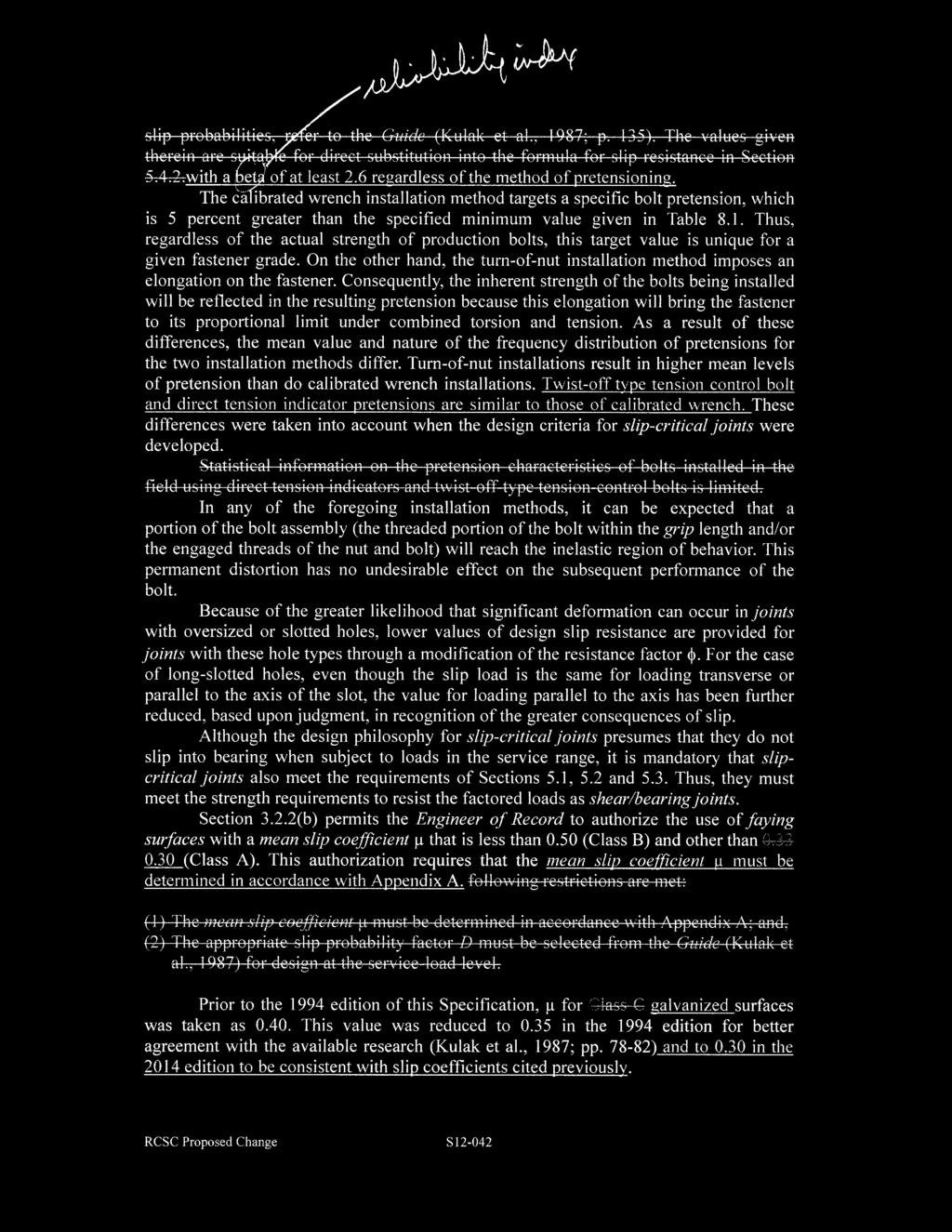
39 Attachment C - Ray Tide
40 Attachment D - Joe Yura
41 Attachment D - Joe Yura
42 Attachment D - Joe Yura
43 Attachment D - Joe Yura
44 Attachment D - Joe Yura
45 RCSC Proposed Change: S Name: Tom Schlafly Phone: Fax: Ballot Actions: Ballot Item # 4 66 Affirmative 1 Negative (Frank) 1 Abstain Proposed Change: 8.1. Snug-Tightened Joints All bolt holes shall be aligned to permit insertion of the bolts without undue damage to the threads. Bolts shall be placed in all holes with washers positioned as required in Section 6.1 and nuts threaded to complete the assembly. Compacting the joint to the snug-tight condition shall progress systematically from the most rigid part of the joint. Snug tight is the condition that exists when all of the plies in a connection have been pulled into firm contact by the bolts in the joint and all of the bolts in the joint have been tightened sufficiently to prevent the removal of the nuts without the use of a wrench. Commentary: As discussed in the Commentary to Section 4, the bolted joints in most shear connections and in many tension connections can be specified as snug-tightened joints. The snug tightened condition is typically achieved with a few impacts of an impact wrench, application of an electric torque wrench until the wrench begins to slow or the full effort of a worker on an ordinary spud wrench. More than one cycle through the bolt pattern may be required to achieve the snug-tightened joint. The splines on twist-off type tension-control bolts may be twisted off or left in place in snug tightened joints. The actual pretensions that result in individual fasteners in snug-tightened joints will vary from joint to joint depending upon the thickness, flatness, and degree of parallelism of the connected plies, as well as the effort applied. In most joints, plies of joints involving material of ordinary thickness and flatness can be drawn into complete contact at relatively low levels of pretension. However, in some joints in thick material or in material with large burrs, it may not be possible to reach continuous contact throughout the faying surface area as is commonly achieved in joints of thinner plates. This is generally not detrimental to the performance of the joint For Committee Use Below Date Received: 5/29/12 Exec Com Meeting: 6/6/12 Forwarded: Yes X /No Committee Assignment: Executive -A. Editorial -B. Nominating -C. Specifications -A.1 X Research -A.2 Membership & Funding -A.3 Education -A.4 Committee Chair: Harrold Task Group #: T.G. Chair: Date Sent to Main Committee: Final Disposition: Revision 4/01/10
46 As used in Section 8.1, the term undue damage is intended to mean damage that would be sufficient to render the product unfit for its intended use. Rationale or Justification for Change (attach additional pages as needed): The proposed revision is in response to occasional inspector requirements to remove the splines of TC bolts even where they are to be snug tight. Ballot Actions and Information: Ballot Item # 4 66 Affirmative 1 Negative (Frank) 1 Abstain Affirmative with Comments: Abolhassan Astaneh: I wonder why it says The splines may be twisted off... OIsn t twisting off the splines costs money? Why not just say may be left in place? May be the intention of mentioning may be twisted off is to ensure that in case the fabricators/erectors tighten the slip critical bolts by mistake and twist off the spline, the inspectors would not force them to take the bolts out and replace them with bolts not tightened beyond the snug-tight position? This can be a good justification, but, then the problem might be that in a snug tight connections some bolts can have spline twisted off and some kept in place (snug tight). Doesn t this create some problem with the behavior and make those tightened bolts unequal to others in carrying the load, at least before they slip? May be it could say something to the effect that in a given snug tight bolted connection either ALL splines should be left in place or ALL should be twisted off. With this change, if some bolts are tightened and spline is twisted off, the others in the same connection can also be tightened to have uniform load distribution to all bolts. Helen Chen: See Attachment E. Robert Hay: This one of the most frequently asked questions regarding snug tight bolts. Jonathan McGormley: I agree with proposal; however, suggest that the word twisted be replaced with removed in the proposed text because twisted would require the bolt be fully pre-tensioned to break the spline. In some cases, engineers do not want anything more than snug-tight and pretensioning the bolt to break the spline will not achieve this result. Floyd Vissat: I support the language presented for Section 8.1, Commentary. It was suggested at the 2012 Specification Committee A.1 meeting that the same language be included in Section 9.1, Commentary; editorial in nature. Negative with Comments: Karl Frank: If the splines are broken off the bolt is not snug tight but fully tensioned. I think the wording should be: The splines on twist-off type tension-control bolts shall be left in place in snug tightened joints. RCSC Proposed Change S12-043
47 Attachment E - Helen Chen RCSC Proposed Change: S Name: Tom Schlafly Phone: schlafly@aisc.org Fax: Ballot Actions: Ballot Item # 4 Proposed Change: 8.1. Snug-Tightened Joints All bolt holes shall be aligned to permit insertion of the bolts without undue damage to the threads. Bolts shall be placed in all holes with washers positioned as required in Section 6.1 and nuts threaded to complete the assembly. Compacting the joint to the snug-tight condition shall progress systematically from the most rigid part of the joint. Snug 1 tight is the condition that exists when all of the plies in a connection have been pulled into firm contact by the bolts in the joint and all of the bolts in the joint have been tightened sufficiently to prevent the removal of the nuts without the use of a wrench. Commentary: As discussed in the Commentary to Section 4, the bolted joints in most shear connections and in many tension connections can be specified as snug-tightened joints. The snug tightened condition is typically achieved with a few impacts of an impact wrench, application of an electric torque wrench until the wrench begins to slow or the full effort of a worker on an ordinary spud wrench. More than one cycle through the bolt pattern may be required to achieve the snug-tightened joint. The splines on twist-off type tension-control bolts may be twisted off or left in place in snug tightened joints. The actual pretensions that result in individual fasteners in snug-tightened joints will vary from joint to joint depending upon the thickness, flatness, and degree of parallelism of the connected plies, as well as the effort applied. In most joints, plies of joints involving material of ordinary thickness and flatness can be drawn into complete contact at relatively low levels of pretension. However, in some joints in thick material or in material with large burrs, it may not be possible to reach continuous contact throughout the faying surface area as is commonly achieved in joints of thinner plates. This is generally not detrimental to the performance of the joint. As used in Section 8.1, the term undue damage is intended to mean damage that would be sufficient to render the product unfit for its intended use For Committee Use Below Date Received: 5/29/12 Exec Com Meeting: 6/6/12 Forwarded: Yes X /No Committee Assignment: Executive -A. Editorial -B. Nominating -C. Specifications -A.1 X Research -A.2 Membership & Funding -A.3 Education -A.4 Committee Chair: Harrold Task Group #: T.G. Chair: Date Sent to Main Committee: Final Disposition: Revision 4/01/10
48 Page: 14 Attachment E - Helen Chen Number: 1 Author: hchen Subject: Sticky Note Date: 1/23/ :42:48 AM The last sentence is in the definition of "snug-tightened joint" and may not be needed (not a spec language).
49 RCSC Proposed Change: S Name: Tom Schlafly Phone: Fax: Ballot Actions: Ballot Item # 5 57 Affirmative 2 Negative (Baxter, Dusicka) 9 Abstain Proposed Change: {Note: Proposed Change S also makes modifications to this section. The proposed changes are mutually exclusive and should not impact technical decisions on this item.} 5.1. Design Shear and Tensile Strengths Shear and tensile strengths shall not be reduced by the installed bolt pretension. For joints, the design shear and tensile strengths shall be taken as the sum of the strengths of the individual bolts. The design strength in shear or the design strength in tension for an ASTM A325, A490, F1852 or F2280 bolt is fr n, where f= 0.75 and: R = FA (Equation 5.1) n n b where R n = nominal strength (shear strength per shear plane or tensile strength) of a bolt, kips; Table 5.1. Nominal Strengths per Unit Area of Bolts Applied Load Condition Nominal Strength per Unit Area, F n, ksi ASTM A325 or F1852 ASTM A490 or F2280 Tension a Static Fatigue See Section 5.5 Shear a,b Threads included in shear plane Threads excluded from shear plane L s 38 in L s > 38 in L s 38 in L s > 38 in For Committee Use Below Date Received: 5/31/12 Exec Com Meeting: 6/6/12 Forwarded: Yes X /No Committee Assignment: Executive -A. Editorial -B. Nominating -C. Specifications -A.1 X Research -A.2 Membership & Funding -A.3 Education -A.4 Committee Chair: Harrold Task Group #: T.G. Chair: Date Sent to Main Committee: Final Disposition: Revision 4/01/10
50 a b Except as required in Section 5.2. Reduction for values for L s > 38 in. applies only when the joint is end loaded, such as splice plates on a beam or column flange. F n = nominal strength per unit area from Table 5.1 for the appropriate applied load conditions, ksi, adjusted for the presence of fillers as required below, and, A b = cross-sectional area based upon the nominal diameter of bolt, in. 2 When a bolt that carries load passes through fillers or shims in a shear plane that are equal to or less than 1/4 in. thick, F n from Table 5.1 shall be used without reduction. When a bolt that carries load passes through fillers or shims that are greater than 1/4 in. thick, they shall be designed in accordance with one of the following procedures: (1) For fillers or shims that are equal to or less than 3/4 in. thick, F n from Table 5.1 shall be multiplied by the factor [1-0.4(t )] but not less than 0.85, where t is the total thickness of fillers or shims, in., up to 3/4 in.; (2) The fillers or shims shall be extended beyond the joint and the filler or shim extension shall be secured with enough bolts to uniformly distribute the total force in the connected element over the combined cross-section of the connected element and the fillers or shims; (3) The size of the joint shall be increased to accommodate a number of bolts that is equivalent to the total number required in (2) above; or, (4) The joint shall be designed as a slip-critical joint using Class A surfaces with Turn-of-Nut pretensioning or Class B surfaces. The slip resistance of the joint shall not be reduced for the presence of fillers or shims. Commentary: The nominal shear and tensile strengths of ASTM A325, F1852, A490 and F2280 bolts are given in Table 5.1. These values are based upon the work of a large number of researchers throughout the world, as reported in the Guide (Kulak et al., 1987; Tide, 2010). The design strength equals the nominal strength multiplied by a resistance factor f. The nominal shear strength is based upon the observation that the shear strength of a single high-strength bolt is about 0.62 times the tensile strength of that bolt (Kulak et al., 1987; pp ). In addition, a reduction factor of 0.90 is applied to joints up to 38 in. in length to account for an increase in bolt force due to minor secondary effects resulting from simplifying assumptions made in the modeling of structures that are commonly accepted in practice (e.g. truss bolted connections assumed pinned in the analysis model). Second order effects such as those resulting from the action of the applied loads on the deformed structure, should be accounted for through a second order analysis of the structure. As noted in Table 5.1, the average shear strength of bolts in joints longer than 38 in. in length is reduced by a factor of 0.75 instead of This factor accounts for both the non-uniform force distribution between the bolts in a long joint and the minor RCSC Proposed Change S12-044
51 secondary effects discussed above. Note that the 0.75 reduction factor does not apply in cases where the distribution of force is essentially uniform along the joint, such as the bolted joints in a shear connection at the end of a deep plate girder. The average ratio of nominal shear strength for bolts with threads included in the shear plane to the nominal shear strength for bolts with threads excluded from the shear plane is 0.83 with a standard deviation of 0.03 (Frank and Yura, 1981). Conservatively, a reduction factor of 0.80 is used to account for the reduction in shear strength for a bolt with threads included in the shear plane but calculated with the area corresponding to the nominal bolt diameter. The case of a bolt in double shear with a non-threaded section in one shear plane and a threaded section in the other shear plane is not covered in this Specification for two reasons. First, the manner in which load is shared between these two dissimilar shear areas is uncertain. Second, the detailer's lack of certainty as to the orientation of the bolt placement might leave both shear planes in the threaded section. Thus, if threads are included in one shear plane, the conservative assumption is made that threads are included in all shear planes. The tensile strength of a high-strength bolt is the product of its ultimate tensile strength per unit area and some area through the threaded portion. This area, called the tensile stress area, is a derived quantity that is a function of the relative thread size and pitch. For the usual sizes of structural bolts, it is about 75 percent of the nominal cross-sectional area of the bolt. Hence, the nominal tensile strengths per unit area given in Table 5.1 are 0.75 times the tensile strength of the bolt material. According to Equation 5.1, the nominal area of the bolt is then used to calculate the design strength in tension. The nominal strengths so-calculated are intended to form the basis for comparison with the externally applied bolt tension plus any additional tension that results from prying action that is produced by deformation of the connected elements. If pretensioned bolts are used in a joint that loads the bolts in tension, the question arises as to whether the pretension and the applied tension are additive. Because the compressed parts are being unloaded during the application of the external tensile force, the increase in bolt tension is minimal until the parts separate (Kulak et al., 1987; pp ). Thus, there will be little increase in bolt force above the pretension load under service loads. After the parts separate, the bolt acts as a tension member, as expected, and its design strength is that given in Equation 5.1 multiplied by the resistance factor f. Pretensioned bolts have torsion present during the installation process. Once the installation is completed, any residual torsion is quite small and will disappear entirely when the fastener is loaded to the point of plate separation. Hence, there is no question of torsion-tension interaction when considering the ultimate tensile strength of a high-strength bolt (Kulak et al., 1987; pp ). When required, pretension is induced in a bolt by imposing a small axial elongation during installation, as described in the Commentary to Section 8. When the joint is subsequently loaded in shear, tension or combined shear and tension, the bolts will undergo significant deformations prior to failure that have the effect of overriding the small axial elongation that was introduced during RCSC Proposed Change S12-044
52 installation, thereby removing the pretension. Measurements taken in laboratory tests confirm that the pretension that would be sustained if the applied load were removed is essentially zero before the bolt fails in shear (Kulak et al., 1987; pp ). Thus, the shear and tensile strengths of a bolt are not affected by the presence of an initial pretension in the bolt. See also the Commentary to Section 5.5. Tests of 24 bolt A /8 diameter connections indicated the reduction in bolt shear strength in connections with filler as required in section 5.1 (1) is limited to 85%. (Borello, Denavit, Hajjar Behavior of Bolted Steel Slip Critical Connections with Fillers UIUC August 2009). Review of available data on slip critical connections revealed that connections with Class A surfaces pretensioned by Turn-of-Nut and connections with Class B surfaces provide a sufficient reliability against slip to eliminate the need to fasten the fills outside the connection or reduce the bolt shear capacity. Grondin, Ming, Josi Slip Critical Bolted Connections - A Reliability Analysis for Design at the Ultimate Limit State. University of Alberta, April Rationale or Justification for Change (attach additional pages as needed): The provisions governing fillers in Section 5.1 have limits and may be incorrect. Example issues include: The equation in (1) stops at ¾ in. Fillers can be thicker. There is a question about whether (4) can be considered valid if slip critical joints need to be checked for bearing. Dr Hajjar conducted a study of the effect of fillers on SC joints. Dr Grondin performed a statistical review of slip critical connections. The proposal is an outcome of those studies. The equations as proposed match the equivalent equations in the AISC Specification. Ballot Actions and Information: Ballot Item # 5 57 Affirmative 2 Negative (Baxter, Dusicka) 9 Abstain Affirmative with Comments: Peter Birkemoe: Looks like TON required for Class A Helen Chen: See Attachment F. Robert Connor: Seems to be some typos where dimensions are made regarding ¼ When a bolt that carries load passes through fillers or shims that are greater than 4 in. thick, they shall be designed in accordance with one of the following procedures: May be good to clarify what they refers to. Fills, fasteners, both. RCSC Proposed Change S12-044
53 Karl Frank: At some point we should consider the equation used in AASHTO which accounts for the 0.85 reduction in an explicit manner. James Ricles: Equal to or less than /4 in. thick. Is it supposed to read one-quarter? Seems the pdf may have mucked up fraction, or there is a typo (this appears twice in the paragraph in question). Bob Shaw: Editorial only Suggest that (4) be split and become (4) The joint shall be designed as a slipcritical joint using Class A surfaces and bolts installed using the turn-of-nut pretensioning method. and (5) The joint shall be designed as a slip-critical joint using class B faying surfaces. Lee Shoemaker: Commentary is worded oddly to start were the tests with 24 bolts in the connection or were there 24 tests? Ray Tide: I agree with the principle of the changes, but I suggest that the commentary section that I have marked up needs a little clean up concerning "brackets and quotation marks". See Attachment G. Negative with Comments: Rodney Baxter: Section 5.1 (4) should include Alt. Design fasteners (F1852/.F2280) for SC-A Joints. Peter Dusicka: Reduction limit of 0.85 may not always be applicable. While appropriate for single side filler of a single splice connection such as those tested with 24 bolts A /8 diameter (Borello, Denavit & Hajjar), single side filler on a double-splice connections have since been shown to result in larger strength reductions, especially for oversized holes. These tests conducted as part of Dusicka s RCSC research were not available at time of Borello et al report. It may be that single side with double-splice connection with large filler thickness is not common/practical in which case this negative vote can be overturned, but I did want to point this out in case this aspect should be considered. Abstain with Comments: Larry Kloiber: The provision in 5.1(4) indicates its propose is to increase reliability of fillers in slip critical joints. It is not clear but it appears to be to be an addition to the Filler Factor provisions to develop multiple fillers and use a factor of 1.0. If this is the intent the provision should be moved to the filler factor section or at least the proper filler factor should be clearly shown for multiple fills. RCSC Proposed Change S12-044
54 Attachment F - Helen Chen were removed is essentially zero before the bolt fails in shear (Kulak et al., 1987; pp ). Thus, the shear and tensile strengths of a bolt are not affected by the presence of an initial pretension in the bolt. See also the Commentary to 1Section 5.5. Tests of 24 bolt A /8 diameter connections indicated the reduction in bolt shear strength in connections with filler as required in section 5.1 (1) is limited to 85%. (Borello, Denavit, Hajjar Behavior of Bolted Steel Slip Critical Connections with Fillers UIUC August 2009). Review of available data on slip critical connections revealed that connections with Class A surfaces pretensioned by Turn-of-Nut and connections with Class B surfaces provide a sufficient reliability against slip to eliminate the need to fasten the fills outside the 2 connection or reduce the bolt shear capacity. Grondin, Ming, Josi Slip Critical Bolted Connections - A Reliability Analysis for Design at the Ultimate Limit State. University of Alberta, April Rationale or Justification for Change (attach additional pages as needed): The provisions governing fillers in Section 5.1 have limits and may be incorrect. Example issues include: The equation in (1) stops at ¾ in. Fillers can be thicker. There is a question about whether (4) can be considered valid if slip critical joints need to be checked for bearing. Dr Hajjar conducted a study of the effect of fillers on SC joints. Dr Grondin performed a statistical review of slip critical connections. The proposal is an outcome of those studies. The equations as proposed match the equivalent equations in the AISC Specification. RCSC Proposed Change S12-044
55 Page: 19 Attachment F - Helen Chen Number: 1 Author: hchen Subject: Sticky Note Date: 1/23/ :13:48 AM add a dash: "1-1/8" Number: 2 Author: hchen Subject: Sticky Note Date: 1/23/ :18:39 AM Should a pair of parentheses be added to the last sentence to be consistent with the other reference in the para.?


56 Attachment G - Ray Tide
57 RCSC Proposed Change: S Name: Chris Curven Phone: Fax: Ballot Actions: Ballot Item # 6 52 Affirmative 10 Negative (Ferrell, Hay, Helwig, Lohr, Mayes, McGormley, G. Mitchell, H. Mitchell, Tide, Ude) 6 Abstain Proposed Changes: Twist-Off-Type Tension-Control Bolt Pretensioning: Twist-off-type tensioncontrol bolt assemblies that meet the requirements of ASTM F1852 or F2280 shall be used. All fastener assemblies shall be installed in accordance with the requirements in Section 8.1 without severing the splined end and with washers positioned as required in Section 6.2. If a splined end is severed during this operation, the fastener assembly shall be removed and replaced. Subsequently, all bolts in the joint shall be pretensioned tightened with the twist-off-type tensioncontrol bolt installation wrench until the splined-end shears off, progressing systematically from the most rigid part of the joint in a manner that will minimize relaxation of previously pretensioned bolts. Commentary: ASTM F1852 and F2280 twist-off-type tension-control bolt assemblies have a splined end that extends beyond the threaded portion of the bolt. During installation, this splined end is gripped by a specially designed wrench chuck and provides a means for turning the nut relative to the bolt. This product is, in fact, based upon a torque-controlled installation method to which the fastener assembly variables affecting torque that were discussed in the Commentary to Section apply, except for wrench calibration, because torque is controlled within the fastener assembly. Twist-off-type tension-control bolt assemblies must be used in the asdelivered, clean, lubricated condition as specified in Section 2. Adherence to the requirements in this Specification, especially those for storage, cleanliness and verification, is necessary for their proper use Turn-of-Nut Pretensioning: The inspector shall observe the pre-installation verification testing required in Section Subsequently, but prior to pretensioning and optional match-marking, it shall be ensured by routine For Committee Use Below Date Received: 5/31/12 Exec Com Meeting: 6/6/12 Forwarded: Yes X /No Committee Assignment: Executive -A. Editorial -B. Nominating -C. Specifications -A.1 X Research -A.2 Membership & Funding -A.3 Education -A.4 Committee Chair: Harrold Task Group #: T.G. Chair: Date Sent to Main Committee: Final Disposition: Revision 4/01/10
58 observation that the plies have been brought into firm contact. Subsequently, it shall be ensured by routine observation that the bolting crew properly rotates the turned element relative to the unturned element by the amount specified in Table 8.2. Alternatively, when fastener assemblies are match-marked after the initial fit-up of the joint but prior to pretensioning, visual inspection after pretensioning is permitted in lieu of routine observation. No further evidence of conformity is required. A pretension that is greater than the value specified in Table 8.1 shall not be cause for rejection. Commentary: Match-marking of the assembly during installation as discussed in the Commentary to Section improves the ability to inspect bolts that have been pretensioned with the turn-of-nut pretensioning method. The sides of nuts and bolt heads that have been impacted sufficiently to induce the Table 8.1 minimum pretension will appear slightly peened. The turn-of-nut pretensioning method, when properly applied and verified during the construction, provides more reliable installed pretensions than after-thefact inspection testing. Therefore, proper inspection of the method is for the inspector to observe the required pre-installation verification testing of the fastener assemblies and the method to be used, followed by monitoring of the work in progress to ensure that the method is routinely and properly applied, or visual inspection of match-marked assemblies. Some problems with the turn-of-nut pretensioning method have been encountered with hot-dip galvanized bolts. In some cases, the problems have been attributed to an especially effective lubricant applied by the manufacturer to ensure that bolts and nuts from stock will meet the ASTM Specification requirements for minimum turns testing of galvanized fasteners. Job-site testing in the tension calibrator demonstrated that the lubricant reduced the coefficient of friction between the bolt and nut to the degree that the full effort of an ironworker using an ordinary spud wrench to snug-tighten the joint actually induced the full required pretension. Also, because the nuts could be removed with an ordinary spud wrench, they were erroneously judged by the inspector to be improperly pretensioned. Excessively lubricated high-strength bolts may require significantly less torque to induce the specified pretension. The required pre-installation verification will reveal this potential problem. Conversely, the absence of lubrication or lack of proper over-tapping can cause seizing of the nut and bolt threads, which will result in a twist failure of the bolt at less than the specified pretension. For such situations, the use of a tension calibrator to check the bolt assemblies to be installed will be helpful in establishing the need for lubrication Calibrated Wrench Pretensioning: The inspector shall observe the daily preinstallation verification testing required in Section Subsequently, but prior to pretensioning, it shall be ensured by routine observation that the plies have been brought into firm contact. Subsequently, it shall be ensured by routine observation that the bolting crew properly applies the calibrated wrench to the RCSC Proposed Change S12-045
59 turned element. No further evidence of conformity is required. A pretension that is greater than the value specified in Table 8.1 shall not be cause for rejection. Commentary: For proper inspection of the method, it is necessary for the inspector to observe the required pre-installation verification testing of the fastener assemblies and the method to be used, followed by monitoring of the work in progress to ensure that the method is routinely and properly applied within the limits on time between removal from protected storage and final pretensioning Twist-Off-Type Tension-Control Bolt Pretensioning: The inspector shall observe the pre-installation verification testing required in Section Subsequently, but prior to pretensioning, it shall be ensured by routine observation that the plies have been brought into firm contact without the splined ends being severed. If the splined end is severed, the bolt must be removed and replaced. Subsequently, it shall be ensured by routine observation that the splined ends are properly severed during installation by the bolting crew. No further evidence of conformity is required. A pretension that is greater than the value specified in Table 8.1 shall not be cause for rejection. Commentary: The sheared-off splined end of an installed twist-off-type tension-control bolt assembly merely signifies that at some time the bolt was subjected to a torque that was adequate to cause the shearing. If in fact all fasteners are individually pretensioned in a single continuous operation without first properly snug-tightening all fasteners, they may give a misleading indication that the bolts have been properly pretensioned. Therefore, it is necessary that the inspector observe the required pre-installation verification testing of the fastener assemblies, and the ability to apply partial tension prior to twist-off is demonstrated. This is followed by monitoring of the work in progress to ensure that the method is routinely and properly applied within the limits on time between removal from protected storage and final twist-off of the splined end. Rationale or Justification for Change (attach additional pages as needed): does not actually state when the installer is to stop tightening or when the bolt is deemed tight. It states what type of installation tool to be used, but not what the installer is looking for. For example, states to rotate the head or nut as specified in table 8.2., states to apply the installation torque determined by the pre-installation verification, and has the installer making sure the achieved gap is less than the job inspection gap. Also, Section is the only installation method that has the inspector verify that snugging of the bolts and plies have taken place before the chosen pretensioning method takes place , ,and would obviously like to have inspection of the snug condition, but it is not listed. RCSC Proposed Change S12-045
60 For example, All bolts shall be installed in accordance with the requirements in Section 8.1, with washers positioned as required in Section 6.2. The installer shall verify that the direct-tension-indicator protrusions have not been compressed to a gap that is less than the job inspection gap during this operation, and if this has occurred, the direct tension indicator shall be removed and replaced. Ballot Actions and Information: Ballot Item # 6 52 Affirmative 10 Negative (Ferrell, Hay, Helwig, Lohr, Mayes, McGormley, G. Mitchell, H. Mitchell, Tide, Ude) 6 Abstain Affirmative with Comments: Peter Birkemoe: Re: The second subsequently if changed to afterward would improve the distinction of the two requirements. The note of indication of impacting in the Commentary to 8.2, Par 1 should be amended unless only impact wrenches can be employed to perform the prescribed turns; if that remains, electric geared reaction wrenches and the hydraulic wrenches that are used on larger fastener assemblies are implicitly disallowed. Helen Chen: See Attachment H. Chris Curven: snug tightened needs to be hyphenated. Bob Shaw: Editorial only suggest th line use twists off instead of shears off Joe Yura: Editorial suggestions remove the word subsequently in all the sections. There is one subsequently followed by another subsequently. The word is just not necessary. Negative with Comments: Doug Ferrell: Commentary of 8.2 adequately explains the requirements of snug-tight and all plies in firm contact before pretensioning. Perhaps this paragraph of commentary should be moved to within the main text of 8.2. This is a necessary requirement of all installation methods, except perhaps DTI. Robert Hay: The proposed additional language regarding the inspection of the snug tight condition would be redundant since 9.1 clearly requires the inspection prior to pretensioning. The modification to is subtle and I have no objection to that. Todd Helwig: While you can tell around the edge that the plies have been brought into contact, how do you tell in the middle of the plate that the plies have been brought into contact? I m don t think this is something that can be reliably checked. RCSC Proposed Change S12-045
61 Ken Lohr: I feel we need to look at the wording proposed and that if changes are needed that they be applied to all methods of installation. Curtis Mayes: This ballot item does not change the spec which is already clear. All Pretensioning methods already require snug tightening section 9.1. This proposal adds redundancy to the spec. We need less redundancy. I might vote for only modifying section with, If the splined end is severed, the bolt must be removed and replaced. Jonathan McGormley: Section 9.1 already requires that the inspector verify that the plies are in firm contact. Section 9.2 which includes all of the tightening methods requires conformance with Section 9.1; therefore, adding repeated language to the tightening methods is verbose. With respect to the langue in Section 9.2.4, it is needed in order to form the basis (start point) for determining whether the pretension method has worked. Eugene Mitchell: Instead of adding the statement to all the other installation methods, delete from the DTI specification. Heath Mitchell: Voted negative with no comment. Ray Tide: Although a slightly different topic, if the above changes are forthcoming then these changes recommended by Chris would require additional changes. One editorial item is raised by Chris in the second paragraph of Section 8.2.3, fifth line where he has changed pretensioned to tightened. However, throughout the total RCSC Spec we use pretensioned. I do NOT agree with this proposed change. Todd Ude: As I read 9.2 and 9.3, they both flow back to require the 9.1 inspection and verification of the snug tight condition (plies in firm contact) prior to final tensioning, regardless of method? This makes additions to and unnecessary? I take no exception and would vote affirmative to the changes proposed for and Abstain with Comments: Matthew Eatherton: I m abstaining on this ballot item because I m not confident about whether the change is appropriate or not. I m unsure if specifying daily inspections in is necessary or too onerous. Also, it s unclear to me why the snug tight condition would need to be inspected for the calibrated wrench method or the twist-off bolt method. RCSC Proposed Change S12-045
62 Attachment H - Helen Chen Commentary: For proper inspection of the method, it is necessary for the inspector to observe the required pre-installation verification testing of the fastener assemblies and the method to be used, followed by monitoring of the work in progress to ensure that the method is routinely and properly applied within the limits on time between removal from protected storage and final pretensioning Twist-Off-Type Tension-Control Bolt Pretensioning: The inspector shall observe the pre-installation verification testing required in Section Subsequently, but prior to pretensioning, it shall be ensured by routine observation that the plies have been brought into firm contact without 1 the splined ends being severed. If the splined end is severed, the bolt must be removed and replaced. Subsequently, it shall be ensured by routine observation that the splined ends are properly severed during installation by the bolting crew. No further evidence of conformity is required. A pretension that is greater than the value specified in Table 8.1 shall not be cause for rejection. Commentary: The sheared-off splined end of an installed twist-off-type tension-control bolt assembly merely signifies that at some time the bolt was subjected to a torque that was adequate to cause the shearing. If in fact all fasteners are individually pretensioned in a single continuous operation without first properly snug-tightening all fasteners, they may give a misleading indication that the bolts have been properly pretensioned. Therefore, it is necessary that the inspector observe the required pre-installation verification testing of the fastener assemblies, and the ability to apply partial tension prior to twist-off is demonstrated. This is followed by monitoring of the work in progress to ensure that the method is routinely and properly applied within the limits on time between removal from protected storage and final twist-off of the splined end. Rationale or Justification for Change (attach additional pages as needed): does not actually state when the installer is to stop tightening or when the bolt is deemed tight. It states what type of installation tool to be used, but not what the installer is looking for. For example, states to rotate the head or nut as specified in table 8.2., states to apply the installation torque determined by the pre-installation verification, and has the installer making sure the achieved gap is less than the job inspection gap. Also, Section is the only installation method that has the inspector verify that snugging of the bolts and plies have taken place before the chosen pretensioning method takes place , ,and would obviously like to have inspection of the snug condition, but it is not listed. For example, All bolts shall be installed in accordance with the requirements in Section 8.1, with washers positioned as required in Section 6.2. The installer shall verify that the direct-tension-indicator protrusions have not been compressed to a gap that is less RCSC Proposed Change S12-045
63 Attachment H - Helen Chen Page: 22 Number: 1 Author: hchen Subject: Sticky Note Date: 1/23/ :21:32 AM change "must" to "shall"
64 RCSC Proposed Change: S Name: Lawrence F. Kruth Phone: Fax: Ballot Actions: Ballot Item # 7 63 Affirmative 3 Negative (Curven, Frank, Helwig) 2 Abstain Proposed Change: {This proposal is in response to persuasive negatives on Proposal S The proposed language modifies the current 2009 Specification language without regard to the previous proposal S which has been terminated.} 1.4. Drawing Information The Engineer of Record shall specify the following information in the contract documents: (1) The ASTM designation and type (Section 2) of bolt to be used; (2) The joint type (Section 4); (3) The required class of slip resistance if slip-critical joints are specified (Section 4); and, (4) Whether slip is checked at the factored-load level or the service-load level, if slip-critical joints are specified (Section 5). Commentary: A summary of the information that the Engineer of Record is required to provide in the contract documents is provided in this Section. The parenthetical reference after each listed item indicates the location of the actual requirement in this Specification. In addition, the approval of the Engineer of Record is required in this Specification in the following cases: (1) For the reuse of non-galvanized ASTM A325 bolts (Section 2.3.3); (2) For the use of alternative washer-type indicating devices that differ from those that meet the requirements of ASTM F959, including the corresponding installation and inspection requirements that are provided by the manufacturer (Section 2.6.2); For Committee Use Below Date Received: 6/8/12 Exec Com Meeting: Forwarded: Yes /No Committee Assignment: Executive -A. Editorial -B. Nominating -C. Specifications -A.1 X Research -A.2 Membership & Funding -A.3 Education -A.4 Committee Chair: Harrold Task Group #: T.G. Chair: Kurth Date Sent to Main Committee: Final Disposition: Revision 4/01/10
65 (3) For the use of alternative-design fasteners, including the corresponding installation and inspection requirements that are provided by the manufacturer (Section 2.8); (4) For the use of faying-surface coatings in slip-critical joints that provide a mean slip coefficient determined per Appendix A, but differing from Class A or Class B (Section 3.2.2(b)); (5) For the use of thermal cutting in the production of bolt holes (Section 3.3); (6) For the use of oversized (Section 3.3.2), short-slotted (Section 3.3.3) or long slotted holes (Section 3.3.4) in lieu of standard holes; (7) For the use of a value of D u other than 1.13 (Section 5.4.1); and, (8) For the use of a value of D other than 0.80 (Section 5.4.2) Bolt Holes The nominal dimensions of standard, oversized, short-slotted and long-slotted holes for high-strength bolts shall be equal to or less than those shown in Table 3.1. Holes larger than those shown in Table 3.1 are permitted when specified or approved by the Engineer of Record. Where thermally cut holes are permitted, the surface roughness profile of the hole shall not exceed 1,000 microinches as defined in ASME B46.1. Occasional gouges not more than z in. in depth are permitted. Thermally cut holes produced by mechanically guided means are permitted in statically loaded joints. Thermally cut holes produced free hand shall be permitted in statically loaded joints if approved by the Engineer of Record. For cyclically loaded joints, thermally cut holes shall be permitted if approved by the Engineer of Record. Commentary: The footnotes in Table 3.1 provide for slight variations in the dimensions of bolt holes from the nominal dimensions. When the dimensions of bolt holes are such that they exceed these permitted variations, the bolt hole must be treated as the next larger type. Slots longer than standard long slots may be required to accommodate construction tolerances or expansion joints. Larger oversized holes may be necessary to accommodate construction tolerances or misalignments. In the latter two cases, the Specification provides no guidance for further reduction of design strengths or allowable loads. Engineering design considerations should include, as a minimum, the effects of edge distance, net section, reduction in clamping force in slip-critical joints, washer requirements, bearing capacity, and hole deformation. For thermally cut holes produced free hand, it is usually necessary to grind the hole surface after thermal cutting in order to achieve a maximum surface roughness profile of 1,000 microinches. Slotted holes in statically loaded joints are often produced by punching or drilling the hole ends and thermally cutting the sides of the slots by mechanically RCSC Proposed Change S12-047
66 guided means. The sides of such slots should be ground smooth, particularly at the junctures of the thermal cuts to the hole ends. For cyclically loaded joints, test results have indicated that when no major slip occurs in the joint, fretting fatigue failure usually occurs in the gross section prior to fatigue failure in the net section (Kulak et al., 1987, pp. 116, 117). Conversely, when slip occurs in the joints of cyclically loaded connections, failure usually occurs in the net section and the edge of a bolt hole becomes the point of crack initiation (Kulak et al., 1987, pp. 118). Therefore, for cyclically loaded joints designed as slip critical, the method used to produce bolt holes (either thermal cutting or drilling) should not influence the ultimate failure load, as failure usually occurs in the gross section when no major slip occurs Standard Holes: In the absence of approval by the Engineer of Record for the use of other hole types, standard Standard holes shall are permitted to be used in all plies of snug-tightened joints as defined in Section 4.1, pretensioned joints as defined in Section 4.2 and slip critical joints as defined in Section 4.3. bolted joints. Table 3.1. Nominal Bolt Hole Dimensions Nominal Bolt Diameter, d b, in. Standard (diameter) Oversized (diameter) Nominal Bolt Hole Dimensions a,b, in. Short-slotted (width length) Long-slotted (width length) ½ 9/16 5/8 9/16 11/16 9/16 1 1/4 5/8 11/16 13/16 11/16 7/8 11/16 1 9/16 ¾ 13/16 15/16 13/ /16 1 7/8 7/8 15/16 1 1/16 15/16 1 1/8 15/16 2 3/ /16 1 ¼ 1 1/16 1 5/16 1 1/16 2 ½ 1 1/16 d b + 1/16 d b + 5/16 (d b + 1/16) (d b + 3/8) (d b + 1/16) (2.5d b) a b The upper tolerance on the tabulated nominal dimensions shall not exceed 1/32 in. Exception: In the width of slotted holes, gouges not more than 1/16 in. deep are permitted. The slightly conical hole that naturally results from punching operations with properly matched punches and dies is acceptable. Commentary: The use of bolt holes 1/16 in. larger than the bolt installed in them has been permitted since the first publication of this Specification. Allen and Fisher (1968) showed that larger holes could be permitted for high-strength bolts without adversely affecting the bolt shear or member bearing strength. However, the slip resistance can be reduced by the failure to achieve adequate pretension initially or by the relaxation of the bolt pretension as the highly compressed material yields at the edge of the hole or slot. The provisions for oversized and slotted holes in this Specification are based upon these findings and the additional concern for the consequences of a slip of significant magnitude if it should occur in the direction RCSC Proposed Change S12-047
67 of the slot. Because an increase in hole size generally reduces the net area of a connected part, the use of oversized holes or of slotted holes is subject to approval by the Engineer of Record Oversized Holes: When approved by the Engineer of Record, oversized holes are permitted in any or all plies of slip-critical joints as defined in Section 4.3. Commentary: See the Commentary to Section Short-Slotted Holes: When approved by the Engineer of Record, sshortslotted holes are permitted in any or all plies of snug-tightened joints as defined in Section 4.1, and pretensioned joints as defined in Section 4.2 and slip critical joints as defined in Section 4.3, provided the applied load is approximately perpendicular (between 80 and 100 degrees) to the axis of the slot. When approved by the Engineer of Record, short-slotted holes are permitted in any or all plies of slip-critical joints as defined in Section 4.3 without regard for the direction of the applied load. Commentary: See the Commentary to Section Long-Slotted Holes: When approved by the Engineer of Record, long-slotted holes are permitted in only one ply at any individual faying surface of snugtightened joints as defined in Section 4.1, and pretensioned joints as defined in Section 4.2, provided the applied load is approximately perpendicular (between 80 and 100 degrees) to the axis of the slot. When approved by the Engineer of Record, long-slotted holes are permitted in one ply only at any individual faying surface of slip-critical joints as defined in Section 4.3 without regard for the direction of the applied load. Fully inserted finger shims between the faying surfaces of load-transmitting elements of bolted joints are not considered a longslotted element of a joint; nor are they considered to be a ply at any individual faying surface. However, finger shims must have the same faying surface as the rest of the plies. Commentary: See the Commentary to Section Finger shims are devices that are often used to permit the alignment and plumbing of structures. When these devices are fully and properly inserted, they do not have the same effect on bolt pretension relaxation or the connection performance, as do long-slotted holes in an outer ply. When fully inserted, the shim provides support around approximately 75 percent of the perimeter of the bolt in contrast to the greatly reduced area that exists with a bolt that is centered in a long slot. Furthermore, finger shims are always enclosed on both sides by the connected material, which should be effective in bridging the space between the fingers. RCSC Proposed Change S12-047
68 Rationale or Justification for Change (attach additional pages as needed): This ballot language is the result of a task group consensus formed following the 2012 RCSC Specification Committee meeting. The requirements for the responsibility in specifying hole types in the RCSC Specification are in conflict with the AISC and CSC Specification. By making this change, the RCSC Specification is more in compliance with the AISC and CSC Specification. The need to use perpendicular short slots is a constructability issue as opposed to a design issue. Due to the varying web thicknesses of beams, the outstanding legs of clip angle connections are required to have short slots in them to meet the fabricator s need to standardize connection clip angles. Short slots are also required by erectors to account for variations in plumbness in the structure due to mis-located anchor rods, sweep in columns and other erection tolerances. These issues are rarely understood or accounted for by the engineer of record. The statement, In the absence of the approval of the Engineer of Record for the use of other hole types, standard holes shall be used has caused engineers to believe that there is something wrong with the use of any other type of hole rather than a standard hole. In order to be conservative, engineers have required that standard holes be used no matter what the fabricator s or erector s reasons might be. Ballot Actions and Information: Ballot Item # 7 63 Affirmative 3 Negative (Curven, Frank, Helwig) 2 Abstain Affirmative with Comments: Abolhassan Astaneh: This is an excellent change. Peter Birkemoe: It would be an easier read if presented as a list of three items Standard holes are permitted to be used in all plies of: 1 Snug-tightened joints as defined in Section 4.1; 2 Pre-tensioned joints.. note that these Ballot Comments are restricted to text input and if the italics shown used in the recommended changes are adopted they should be used in a parallel manner in the series whether a list is used or not. Allen Harrold: Table 3.1 has a variety of bogus entries due to format conversions, however there were no proposed changes to the table in actuality. Editorial corrections will be made to insure that the table reads correctly in the final version. Joe Yura: Although it is not part of this ballot, item 1.4 (4) needs to be removed because of the changes recommended in Ballot #3 RCSC Proposed Change S12-047
69 Negative with Comments: Chris Curven: Current wording is concise in its requirements. It allows short-slotted allows but keeps the EOR in the decision making process. Proposed changes makes it easy for fabricators to misinterpret the specification. For 3.3.1, new wording, in particular permitted implies that hole type is an option without contacting EOR. For 3.3.3, the first sentence makes short-slotted hole permissible without contacting EOR. Current wording clearly states that the EOR must approve hole type, not limiting them. The RCSC need not follow AISC s lead. They are two different groups. AISC can choose not to adopt the RCSC specification. Karl Frank: I firmly believe that short slotted holes should not be used unless the EOR approves their use. I would think the commentary could be expanded to point out in simple shear connections of gravity loaded beams, short slotted holes in conjunction with snug tight bolts can provide the shear capacity and allow the beam to rotate which matches the design assumptions. Todd Helwig: I don t have a problem with getting rid of the first sentence of Section 3.3.1; however I don t agree with the changes to the change on the paragraph in section While the use of slotted holes can make erection easier, I think the EOR needs to be consulted in many applications where the use of the slot can affect the behavior of the structural member. The end connections are very important to the stability of the member and the use of slotted holes can result in relatively large twists/lateral movements that can affect the behavior of the member. There are cases where member stability could be affected if a short slotted hole is used with a snug tight bolt. 5/10/13 Proposal with changes to satisfy the Frank and Helwig negatives: {Modifications are shown as either double strikeout or double underscore to distinguish the proposed changes from the balloted changes. Changes exist in the Commentary to Sections 3.3.1, 3.3.2, and 3.3.3} 1.4. Drawing Information The Engineer of Record shall specify the following information in the contract documents: (5) The ASTM designation and type (Section 2) of bolt to be used; (6) The joint type (Section 4); (7) The required class of slip resistance if slip-critical joints are specified (Section 4); and, (8) Whether slip is checked at the factored-load level or the service-load level, if slip-critical joints are specified (Section 5). Commentary: A summary of the information that the Engineer of Record is required to provide in the contract documents is provided in this Section. The parenthetical reference after each listed item indicates the location of the actual requirement in this Specification. In addition, the approval of the Engineer of Record is required in this Specification in the following cases: (9) For the reuse of non-galvanized ASTM A325 bolts (Section 2.3.3); (10) For the use of alternative washer-type indicating devices that differ from those that meet the requirements of ASTM F959, including the RCSC Proposed Change S12-047
70 corresponding installation and inspection requirements that are provided by the manufacturer (Section 2.6.2); (11) For the use of alternative-design fasteners, including the corresponding installation and inspection requirements that are provided by the manufacturer (Section 2.8); (12) For the use of faying-surface coatings in slip-critical joints that provide a mean slip coefficient determined per Appendix A, but differing from Class A or Class B (Section 3.2.2(b)); (13) For the use of thermal cutting in the production of bolt holes (Section 3.3); (14) For the use of oversized (Section 3.3.2), short-slotted (Section 3.3.3) or long slotted holes (Section 3.3.4) in lieu of standard holes; (15) For the use of a value of D u other than 1.13 (Section 5.4.1); and, (16) For the use of a value of D other than 0.80 (Section 5.4.2) Bolt Holes The nominal dimensions of standard, oversized, short-slotted and long-slotted holes for high-strength bolts shall be equal to or less than those shown in Table 3.1. Holes larger than those shown in Table 3.1 are permitted when specified or approved by the Engineer of Record. Where thermally cut holes are permitted, the surface roughness profile of the hole shall not exceed 1,000 microinches as defined in ASME B46.1. Occasional gouges not more than z in. in depth are permitted. Thermally cut holes produced by mechanically guided means are permitted in statically loaded joints. Thermally cut holes produced free hand shall be permitted in statically loaded joints if approved by the Engineer of Record. For cyclically loaded joints, thermally cut holes shall be permitted if approved by the Engineer of Record. Commentary: The footnotes in Table 3.1 provide for slight variations in the dimensions of bolt holes from the nominal dimensions. When the dimensions of bolt holes are such that they exceed these permitted variations, the bolt hole must be treated as the next larger type. Slots longer than standard long slots may be required to accommodate construction tolerances or expansion joints. Larger oversized holes may be necessary to accommodate construction tolerances or misalignments. In the latter two cases, the Specification provides no guidance for further reduction of design strengths or allowable loads. Engineering design considerations should include, as a minimum, the effects of edge distance, net section, reduction in clamping force in slip-critical joints, washer requirements, bearing capacity, and hole deformation. RCSC Proposed Change S12-047
71 For thermally cut holes produced free hand, it is usually necessary to grind the hole surface after thermal cutting in order to achieve a maximum surface roughness profile of 1,000 microinches. Slotted holes in statically loaded joints are often produced by punching or drilling the hole ends and thermally cutting the sides of the slots by mechanically guided means. The sides of such slots should be ground smooth, particularly at the junctures of the thermal cuts to the hole ends. For cyclically loaded joints, test results have indicated that when no major slip occurs in the joint, fretting fatigue failure usually occurs in the gross section prior to fatigue failure in the net section (Kulak et al., 1987, pp. 116, 117). Conversely, when slip occurs in the joints of cyclically loaded connections, failure usually occurs in the net section and the edge of a bolt hole becomes the point of crack initiation (Kulak et al., 1987, pp. 118). Therefore, for cyclically loaded joints designed as slip critical, the method used to produce bolt holes (either thermal cutting or drilling) should not influence the ultimate failure load, as failure usually occurs in the gross section when no major slip occurs Standard Holes: In the absence of approval by the Engineer of Record for the use of other hole types, standard Standard holes shall are permitted to be used in all plies of snug-tightened joints as defined in Section 4.1, pretensioned joints as defined in Section 4.2 and slip critical joints as defined in Section 4.3. bolted joints. Table 3.1. Nominal Bolt Hole Dimensions Nominal Bolt Diameter, d b, in. Standard (diameter) Oversized (diameter) Nominal Bolt Hole Dimensions a,b, in. Short-slotted (width length) Long-slotted (width length) ½ 9/16 5/8 9/16 11/16 9/16 1 1/4 5/8 11/16 13/16 11/16 7/8 11/16 1 9/16 ¾ 13/16 15/16 13/ /16 1 7/8 7/8 15/16 1 1/16 15/16 1 1/8 15/16 2 3/ /16 1 ¼ 1 1/16 1 5/16 1 1/16 2 ½ 1 1/16 d b + 1/16 d b + 5/16 (d b + 1/16) (d b + 3/8) (d b + 1/16) (2.5d b) a b The upper tolerance on the tabulated nominal dimensions shall not exceed 1/32 in. Exception: In the width of slotted holes, gouges not more than 1/16 in. deep are permitted. The slightly conical hole that naturally results from punching operations with properly matched punches and dies is acceptable. Commentary: The use of bolt holes 1/16 in. larger than the bolt installed in them has been permitted since the first publication of this Specification. Allen and Fisher (1968) showed that larger holes could be permitted for high-strength bolts without adversely affecting the bolt shear or member bearing strength. However, the slip RCSC Proposed Change S12-047
72 resistance can be reduced by the failure to achieve adequate pretension initially or by the relaxation of the bolt pretension as the highly compressed material yields at the edge of the hole or slot. The provisions for oversized and slotted holes in this Specification are based upon these findings and the additional concern for the consequences of a slip of significant magnitude if it should occur in the direction of the slot. Because an increase in hole size generally reduces the net area of a connected part, the use of oversized holes or of slotted holes is subject to approval by the Engineer of Record Oversized Holes: When approved by the Engineer of Record, oversized holes are permitted in any or all plies of slip-critical joints as defined in Section 4.3. Commentary: See the Commentary to Section The provisions for oversized holes in this Specification are based upon these findings and the additional concern for the consequences of a slip of significant magnitude if it should occur in the oversized hole. Because an increase in hole size generally reduces the net area of a connected part, the use of oversized holes is subject to approval by the Engineer of Record Short-Slotted Holes: When approved by the Engineer of Record, sshortslotted holes are permitted in any or all plies of snug-tightened joints as defined in Section 4.1, and pretensioned joints as defined in Section 4.2 and slip critical joints as defined in Section 4.3, provided the applied load is approximately perpendicular (between 80 and 100 degrees) to the axis of the slot. When approved by the Engineer of Record, short-slotted holes are permitted in any or all plies of slip-critical joints as defined in Section 4.3 without regard for the direction of the applied load. Commentary: See the Commentary to Section The use of short-slotted holes approximately perpendicular to the applied load in conjunction with snug tight bolts can provide the shear capacity and may allow the beam to rotate which matches the design assumptions. End connections are very important to the stability of the member. The use of short-slotted holes may result in twists and or lateral movement that may affect the behavior of the member. In cases where the use of short-slotted holes affects the behavior of the structural member, the Engineer of Record should be consulted. The provisions for short-slotted holes in a direction that is other than perpendicular to the applied loading are based upon these findings and the additional concern for the consequences of a slip of significant magnitude if it should occur in the short-slotted hole. Because an increase in hole size generally reduces the net area of a connected part, the use of slotted holes other than RCSC Proposed Change S12-047
73 perpendicular to the applied loading is subject to approval by the Engineer of Record Long-Slotted Holes: When approved by the Engineer of Record, long-slotted holes are permitted in only one ply at any individual faying surface of snugtightened joints as defined in Section 4.1, and pretensioned joints as defined in Section 4.2, provided the applied load is approximately perpendicular (between 80 and 100 degrees) to the axis of the slot. When approved by the Engineer of Record, long-slotted holes are permitted in one ply only at any individual faying surface of slip-critical joints as defined in Section 4.3 without regard for the direction of the applied load. Fully inserted finger shims between the faying surfaces of load-transmitting elements of bolted joints are not considered a longslotted element of a joint; nor are they considered to be a ply at any individual faying surface. However, finger shims must have the same faying surface as the rest of the plies. Commentary: See the Commentary to Section Finger shims are devices that are often used to permit the alignment and plumbing of structures. When these devices are fully and properly inserted, they do not have the same effect on bolt pretension relaxation or the connection performance, as do long-slotted holes in an outer ply. When fully inserted, the shim provides support around approximately 75 percent of the perimeter of the bolt in contrast to the greatly reduced area that exists with a bolt that is centered in a long slot. Furthermore, finger shims are always enclosed on both sides by the connected material, which should be effective in bridging the space between the fingers. RCSC Proposed Change S12-047
74 RCSC Proposed Change: S Name: Allen Harrold Phone: Fax: Ballot Actions: Approved Editorially by Exec Committee on 2/25/13 Proposed Change: Section Referenced Standards and Specifications The following standards and specifications are referenced herein: American Institute of Steel Construction Specification for Structural Steel Buildings, June 22, 2010 American National Standards Institute ANSI/ASME B Fasteners for Use in Structural Applications American Society for Testing and Materials ASTM International ASTM A Standard Specification for Zinc (Hot-Dip Galvanized) Coatings on Iron and Steel Products {Remainder of section is unchanged.} Rationale or Justification for Change (attach additional pages as needed): ASTM now goes by the name ASTM International without actually spelling out what the letters ASTM formerly meant. This is in line with their efforts to expand recognition of these standards worldwide and diminish the old label of American Society For Committee Use Below Date Received: _Nov 2012 Exec Com Meeting: 2/25/13 Forwarded: Yes /No Committee Assignment: Executive -A. Editorial -B. Nominating -C. Specifications -A.1 Research -A.2 Membership & Funding -A.3 Education -A.4 Committee Chair: Task Group #: T.G. Chair: Date Sent to Main Committee: Final Disposition: Approved - Editorial Revision 4/01/10
75 RCSC Proposed Change: S Name: Rich Brown Phone: Fax: Proposed Change: Direct-Tension-Indicator Pretensioning: When the direct-tension-indicator pretensioning method is used, an ASTM F436 washer shall be used as follows: (1) When the nut is turned and the direct tension indicator is located under the bolt head, an ASTM F436 washer shall be used under the nut; (2) When the nut is turned and the direct tension indicator is located under the nut, an ASTM F436 washer shall be used between the nut and the direct tension indicator except when using direct tension indicator designs with curved protrusions, then the ASTM F436 washer can be eliminated; (3) When the bolt head is turned and the direct tension indicator is located under the nut, an ASTM F436 washer shall be used under the bolt head, except when using direct tension indicator designs with curved protrusions, then the ASTM F436 washer can be eliminated; and, (4) When the bolt head is turned and the direct tension indicator is located under the bolt head, an ASTM F436 washer shall be used between the bolt head and the direct tension indicator. {Table 6.1 is not included here. There are no changes to the table.} {Note the commentary is for the entire Section 6, not just section } Commentary: It is important that shop drawings and connection details clearly reflect the number and disposition of washers when they are required, especially the thick hardened washers or plate washers that are required for some slotted hole applications. The total thickness of washers in the grip affects the length of bolt that must be supplied and used. The primary function of washers is to provide a hardened non-galling surface under the turned element, particularly for torque-based pretensioning methods such as the calibrated wrench pretensioning method and twist-off-type tension-control bolt pretensioning method. Circular flat washers that meet the requirements of ASTM F436 provide both a hardened non-galling surface and an increase in bearing area that is approximately 50 percent larger than that provided by a heavy-hex bolt head or nut. However, tests have shown that washers of the standard E in. thickness have a minor influence on the pressure distribution of the induced bolt pretension. Furthermore, they showed that a larger thickness is required when ASTM A490 bolts are used with material that has a minimum specified yield strength that is less than 40 ksi. This is necessary to For Committee Use Below Date Received: 02/12/13 Exec Com Meeting: Forwarded: Yes /No Committee Assignment: Executive -A. Editorial -B. Nominating -C. Specifications -A.1 Research -A.2 Membership & Funding -A.3 Education -A.4 Committee Chair: Task Group #: T.G. Chair: Date Sent to Main Committee: Final Disposition: Revision 4/01/10
76 mitigate the effects of local yielding of the material in the vicinity of the contact area of the head and nut. The requirement for standard thickness hardened washers, when such washers are specified, is waived for alternative design fasteners that incorporate a bearing surface under the head of the same diameter as the hardened washer. The elimination of the hardened washer when using Direct Tension Indicators under the turned element must be approved during the Pre-Verification Installation Tests. Heat-treated washers not less than 5/16 in. thick are required to cover oversized and short-slotted holes in external plies, when ASTM A490 or F2280 bolts of diameter larger than 1 in. are used, except as permitted by Table 6.1 footnotes a and d. This was found necessary to distribute the high clamping pressure so as to prevent collapse of the hole perimeter and enable the development of the desired clamping force. Preliminary investigation has shown that a similar but less severe deformation occurs when oversized or slotted holes are in the interior plies. The reduction in clamping force may be offset by keying, which tends to increase the resistance to slip. These effects are accentuated in joints of thin plies. When long-slotted holes occur in an outer ply, ⅜ in. thick plate washers or continuous bars and one ASTM F436 washer are required in Table 6.1. This requirement can be satisfied with material of any structural grade. Alternatively, either of the following options can be used: (1) The use of material with F y greater than 40 ksi will eliminate the need to also provide ASTM F436 washers in accordance with the requirements in Section for ASTM A490 or F2280 bolts of any diameter; or, (2) Material with F y equal to or less than 40 ksi can be used with ASTM F436 washers in accordance with the requirements in Section This specification previously required a washer under bolt heads with a bearing area smaller than that provided by an ASTM F436 washer. Tests indicate that the pretension achieved with a bolt having the minimum ASTM F1852 or F2280 bearing circle diameter is the same as that of a bolt with the larger bearing circle diameter equal to the size of an ASTM F436 washer, provided that the hole size meets the RCSC Specification limitations (Schnupp, 2003). Rationale or Justification for Change (attach additional pages as needed): Research performed and published in the Engineering Journal by Douglas B. Cleary, William T. Riddell and Christopher J. Lacke of Rowan University on the Effect of Washer Placement on the Performance of Direct Tension Indicators with Curved Protrusions, provides evidence that the use of an ASTM F436 washer is not needed in these applications. Excerpt from Summary and Conclusions: Based on the results of this test program, it is concluded that the use of direct tension indicators with curved protrusions with or without hardened washers against the turned element for ASTM A325 3/4- and 7/8-in.-diameter bolts and ASTM A490 1-in.-diameter bolts results in comparable performance in providing the required bolt pretension if a Grade DH or harder nut is used. In addition, the presence or absence of the hardened washer made no difference in the performance of the direct tension indicators at the load levels required to close all but one or all of the gaps. RCSC Proposed Change S13-049

77 Engineering Journal American lnstitute of Steel Construction g.'. -t. ;' ;,1 ;,,,, i,j ;;:; :;;;;.!* The Eff+ct 0f :,1 : 87
78 Effect of Washer Placement on Performance of Direct Tension Indicators with Curved Protrusions Douglas B. Cleary, William T. Riddell and Christopher J. Lacke ABSTRACT A series of tests was performed to evaluate the effect of a hardened washer placed between the turned element and a direct tension indicator (DTI) with curved protrusions. Configurations with w-, d- and 1.0-in.-diameter bolts with and without hardened washers were evaluated. Tests were also performed with w- and d-in. bolts using a new type of DTI, where the DTI is staked to a nut. The purpose of these tests was to compare the performance of the various configurations, as measured by the number of gaps open at the specified pretension level, the load required to close at least half of the gaps, and the tensile load on the bolts when all or all but one of the gaps in the DTI are closed. When an ASTM A563 grade DH nut was used for a given bolt diameter, some differences were observed to be statistically significant. However, no consistent trends were observed in these differences, and the actual differences were of the same order of magnitude as the load increments used in testing. Therefore, it was concluded that there are no practical differences between the various configurations considered when grade DH nuts are used. However, the DTI did not perform well without a secondary hardened washer when an ASTM A563 Grade C nut was used. Keywords: direct tension indicators, hardness, washers, bolting. Tension indicating washers, commonly called direct tension indicators (DTIs), are one of several methods used to achieve or demonstrate adequate bolt pretension when such pretension is required in a bolted connection. Other methods include turn-of-the-nut, calibrated wrenches, and twist-off-type tension-control bolts. astm F states that a direct tension indicator is a washer-type element inserted under the bolt head or hardened washer, having the capability of indicating the achievement of a required minimum bolt tension by the degree of direct tension indicator plastic deformation. The plastic deformation is indicated by the collapse of protrusions on the face of the tension indicating washer. The extent to which the protrusions have collapsed is determined by the number of gaps between protrusions that a in.-thick indicator can be inserted. Direct tension indicators were introduced in the 1960s and their design has evolved over the ensuing years. Previous studies of use of DTIs in structural connections can be found in the literature (Schmeckpeper et al., 1999; Struik et al., 1973). Douglas B. Cleary, Ph.D., P.E., Associate Professor, Department of Civil and Environmental Engineering, Rowan University, Glassboro, NJ (corresponding author). cleary@rowan.edu William T. Riddell, Ph.D., Associate Professor, Department of Civil and Environmental Engineering, Rowan University, Glassboro, NJ. riddell@ rowan.edu Christopher J. Lacke, Ph.D., Associate Professor, Department of Mathematics, Rowan University, Glassboro, NJ. lacke@rowan.edu The Research Council on Structural Connections (RCSC, 2004) Specification for Structural Joints Using ASTM A325 or A490 Bolts notes that washers are not required in pretensioned joints and slip-critical joints except in cases of sloping surfaces, oversized or slotted holes, and for certain situations with lower yield strength base material and A490 connectors. In addition, there are requirements for the use of washers under turned elements when using calibrated wrench pretensioning, twist-off-type, tension-control bolt pretensioning and direct tension indicators. As noted in the Commentary of Section 6 of the RCSC specification, The primary function of washers is to provide a hardened non-galling surface under the turned element, particularly for torque-based pretensioning methods Although direct tension indicators are not torque-based, the specification does require an astm F436 washer between the direct tension indicator and the turned element. The original tension indicating washers developed by Cooper and Turner Ltd. required use of hardened washers per the manufacturer s installation instructions because the indicator protrusions in some cases were outside the bearing surface of the bolt or nut. In addition, the protrusions were harder and had a straight-sided shape that could cut or gall the bearing surface of the turned element (Laboratory Testing Inc., 1999). An amendment to astm F959 in 1993 ensured that DTIs conforming to that specification would have protrusions that fall within the geometric limits of bolt or nut bearing surfaces. The hardness of current DTIs varies by manufacturer. ENGINEERING JOURNAL / SECOND QUARTER / 2012 / 55


79 Diameter, in. Table 1. Matrix of Configurations Considered in Testing Type Surface Finish Hardened Washer Nut Grade Number of Tests TurnaSure DTI Lot 343I76 ¾ 325 Plain Yes DH 30 Lot 343I76 ¾ 325 Plain No DH 30 Lot 783F63-3 d 325 Plain Yes DH 30 Lot 783F63-3 d 325 Plain No DH 30 Lot 014B Plain Yes DH 30 Lot 014B Plain No DH 30 Lot 343I74 ¾ 325 Plain No DH 10 Lot 783F63-3 d 325 Plain No C 10 TurnAnut DTI 34TNA6A ¾ 325 Plain No DH 30 34TNA7A ¾ 325 Galvanized No DH 30 78TNA6A d 325 Plain No DH 30 78TNA6A d 325 Galvanized No DH 30 PURPOSE AND SCOPE The purpose of this study was to evaluate the performance of direct tension indicators with curved protrusions for various washer configurations under controlled laboratory conditions. Tests were performed for astm A325 w- and d-in.-diameter bolts and astm A490 1-in.-diameter bolts with standard astm F959 direct tension indicators, with and without astm F436 standard hardened washers against astm A563 Grade DH nuts. For the astm A325 w- and d-in. bolts, both galvanized and plain finish proprietary TurnAnut DTIs are also evaluated. The TurnAnut DTI consists of a nut to which a DTI has been attached by staking. An additional test series with d-in.-diameter bolts with astm A563 Grade C nuts was also performed. All DTIs were manufactured by TurnaSure, llc. The test conditions are summarized in Table 1. CODE REQUIREMENTS FOR DIRECT TENSION INDICATORS Direct tension indicators must meet the requirements of astm F959. Section 7 of the RCSC Specification describes the requirements to verify that fastener assemblies (a) TurnaSure DTI (b) TurnaSure TurnAnut DTI Fig. 1. Views of TurnaSure DTI and TurnAnut DTI. The images show the devices before and after testing. 56 / ENGINEERING JOURNAL / SECOND QUARTER / 2012

80 Nominal Bolt Diameter, d b, in. Table 2. Relevant Tensile Forces for Pretensioned and Slip Critical Bolts Specified Minimum Bolt Pretension, T m, kips ASTM A325 Bolts ASTM A490 Bolts 1.05 times Specified Minimum Bolt Pretension, kips ASTM A325 Bolts ASTM A490 Bolts Minimum Tensile Capacity, kips ASTM A325 Bolts ASTM A490 Bolts ¾ d and procedures result in the required post tightening performance (RCSC, 2004). The specification calls for the use of a tension calibrator to confirm the performance of the fastener assembly and the pretensioning method to be used by the bolting crew. Section 8 describes installation of fastener components. Section specifically describes directtension-indicator pretensioning. The RCSC Specification calls for a representative sample of fastener assemblies to be tested for each combination of diameter, length, grade and lot to be used. In the snug-tight condition at least half of the DTI gaps must remain open. Testing then proceeds until at least half of the gaps are closed to a in. feeler gage. The purpose of the testing is to ascertain that the fastener assembly and fastening procedure develops a pretension equal to or greater than 1.05 times the values specified in Table 8.1 of the RCSC Specification. The values from Table 8.1 of interest to this test program, as well as the values scaled by 1.05 used for initial pretensioning in this study are reported in Table 2. EXPERIMENTAL PROGRAM The experimental program consisted of tension tests of TurnaSsure DTIs (Type 325 w in., d in. and Type in.) and TurnaSure TurnAnut DTIs (Type 325 w in. diameter and d in. diameter). The devices tested are shown in Figure 1. The tests of DTIs were performed with four configurations, including plain-finish DTIs bearing directly against the face of the nut, plain-finish DTIs bearing against a hardened washer, and both plain and mechanically galvanized TurnAnut DTIs as shown in Figures 1 and 2. In the initial round of testing, 30 assemblies of each configuration were tested with Grade DH nuts. All DTIs of the same size were from the same production lot in the initial round of testing. Two additional series consisted of 10 assembly tests each. The first employed w-in.-diameter assemblies with Grade DH nuts and no hardened washer, employing DTIs from a different production lot than was used in the initial round. The second additional series was for d-in. assemblies using the same DTI lot as the initial series against Grade C nuts without hardened washers. The nuts were turned with an electric wrench. A summary of the program was provided in Table 1. The Rockwell hardness measurements for all DTIs, nuts, and washers used are shown in Table 3. While the nuts were tightened, the tension of the bolts was measured with a Skidmore-Wilhelm bolt tension calibrator with a digital readout. For loading, the bolts were placed through the back of the calibrator and the nut was the turned element. The bolts were initially tensioned to 1.05 times the load specified in Table 8.1 of the RCSC Specification. The number of gaps open more than in. was determined using a feeler gauge. The bolts were then subjected to incremental increases in tension, with the number of open gaps measured and recorded at each increment, until only one gap remained open. The load increments were on the order of 1 kip to 3 kips. In some instances, the final load increment resulted in all gaps closing. The tension load required to close all or all but one gap was recorded. After loading, it was verified that the nut could be rethreaded for the length of the bolt. The loading plates of the bolt tension calibrator required re-facing at regular intervals. No more than 20 test repetitions were performed on a plate without re-facing. The test equipment is shown in Figure 3. Fig 2. Test configurations from left to right; DTI without washer, DTI with washer, plain TurnAnut DTI, galvanized TurnAnut DTI. ENGINEERING JOURNAL / SECOND QUARTER / 2012 / 57
 Lot 783F63-3 d 94.4/1.74 (B) 40.2/1.64 (C) 26.6/1.75 (C) Lot 014B10 1 83.4/8.91 (B) 42.8/0.84 (C) 28.9/2.53 (C) Lot 343I74 ¾ 90.4/3.80 (B) 43.0/2.53 (C) 30.3/2.")
81 Table 3. Rockwell Hardness of Connection Components (Scale) Diameter, in. TurnaSure DTI Tests with DH Nuts DTI Avg./STD Washer Avg./STD Nut Avg./STD Lot 343I76 ¾ 87.6/3.09 (B) 39.1/2.48 (C) 30.1/0.42 (C) Lot 783F63-3 d 94.4/1.74 (B) 40.2/1.64 (C) 26.6/1.75 (C) Lot 014B /8.91 (B) 42.8/0.84 (C) 28.9/2.53 (C) Lot 343I74 ¾ 90.4/3.80 (B) 43.0/2.53 (C) 30.3/2.84 (C) TurnaSure DTI Tests with C Nuts Lot 783F63-3 d 94.4/1.74 (B) Not used 88.37/3.00 (B) RESULTS Results of three key load points are reported in this study. The first result reported is the number of gaps open when the pretension in the bolt reaches 1.05 times that specified in Table 8.1 of the RCSC Specification. These required pretension values were noted in Table 2. These data are used, similar to pre-installation verification of assemblies as outlined in Section 7 of the RCSC Specification, to verify that the required pretension is reached. The required pretension values should be reached prior to half of the DTI gaps closing. The second result reported is the load required to close all or all but one of the DTI gaps. The third finding is the distribution of measured bolt tensions when the DTI indicated that the specified bolt pretension requirements were met (half of the gaps closed). The average numbers of gaps open at 1.05 times the minimum pretension load and the standard deviation of these results are provided in Table 4. Table 5 provides the distribution of the number of gaps open at this load from tests on w, d- and 1-in.-diameter bolts, respectively. The preload values were 29 kips for w in.-diameter A325 bolts, 41 kips for d in.-diameter A325 bolts, and 67 kips for 1 in.-diameter A490 bolts. Fig. 3. Test setup. 58 / ENGINEERING JOURNAL / SECOND QUARTER / 2012
RESEARCH COUNCIL ON STRUCTURAL CONNECTIONS (RCSC) MINUTES of SPECIFICATION COMMITTEE A.1 5 June 2014, 8:00AM (MDT), Estes Park, CO
 MINUTES of SPECIFICATION COMMITTEE A.1 5 June 2014, 8:00AM (MDT), Estes Park, CO") RESEARCH COUNCIL ON STRUCTURAL CONNECTIONS (RCSC) MINUTES of SPECIFICATION COMMITTEE A.1 5 June 2014, 8:00AM (MDT), Estes Park, CO Members Present: (34) Members Absent: (20) Guests: (19) R. Baxter, P.
RESEARCH COUNCIL ON STRUCTURAL CONNECTIONS (RCSC) MINUTES of SPECIFICATION COMMITTEE A.1 5 June 2014, 8:00AM (MDT), Estes Park, CO Members Present: (34) Members Absent: (20) Guests: (19) R. Baxter, P.
RESEARCH COUNCIL ON STRUCTURAL CONNECTIONS (RCSC) MINUTES of SPECIFICATION COMMITTEE A.1 16 June 2011, 8:00AM, Oakland, CA
 MINUTES of SPECIFICATION COMMITTEE A.1 16 June 2011, 8:00AM, Oakland, CA") RESEARCH COUNCIL ON STRUCTURAL CONNECTIONS (RCSC) MINUTES of SPECIFICATION COMMITTEE A.1 16 June 2011, 8:00AM, Oakland, CA Members P. Birkemoe, D. Bogarty, R. Brown, B. Cornelissen, C. Curven, N. Deal,
RESEARCH COUNCIL ON STRUCTURAL CONNECTIONS (RCSC) MINUTES of SPECIFICATION COMMITTEE A.1 16 June 2011, 8:00AM, Oakland, CA Members P. Birkemoe, D. Bogarty, R. Brown, B. Cornelissen, C. Curven, N. Deal,
2017 Annual Meeting. RCSC Specification Committee Agenda. 1:15 p.m. 2:15 p.m., June 8, Radisson Blu Mall of America Bloomington, MN
 2017 Annual Meeting RCSC Specification Committee Agenda 1:15 p.m. 2:15 p.m., June 8, 2017 Radisson Blu Mall of America Bloomington, MN 1. Welcome and Introduction 2. Approval of Agenda 3. Approval of Summary
RCSC Specification Committee, Task Group 1, General Requirements June 9, 2016
 RCSC Specification Committee, Task Group 1, General Requirements June 9, 2016 1. Introduction a. Scope of Task Group 1 b. Introduction of Members c. Adoption of Agenda Holiday Inn Lafayette--City Centre,
Procedure for Wrench Calibration and Snug Tightening
 Procedure for Wrench Calibration and Snug Tightening 1. Scope: This procedure provides the method for calibration of a manual torque wrench or an adjustable impact wrench and the snug tightening procedure
From reformatting the entire
 Revised RCSC Specification: Simplified, Clarified, and Improved Charles J. Carter, S.E., P.E. and Heath E. Mitchell From reformatting the entire document for simplicity, ease of use and clarity to adding
Instruction Manual for installing
 Instruction Manual for installing Preloaded (HSFG) Bolting with TurnaSure DIRECT TENSION INDICATORS CE Marked EN 14399-9 TurnaSure LLC TABLE OF CONTENTS Introduction... 1 Theory of Preloaded Bolting Assemblies...
Instruction Manual for installing
 Instruction Manual for installing Preloaded (HSFG) Bolting with TurnaSure DIRECT TENSION INDICATORS TurnaSure LLC TABLE OF CONTENTS Introduction... 1 Theory of Preloaded Bolting Assemblies... 2 Tightening
Structural Bolting. Notice the Grade 5 has a much smaller head configuration and a shorter shank then the grade A325 structural bolt.
 Structural Bolting ASTM F3125/F3125M is a structural bolt specification covering inch and metric bolt grades. This specification contains 4 inch series bolting grades: A325, F1852, A490, and F2280. These
2016 AASHTO BRIDGE COMMITTEE AGENDA ITEM: 24 (REVISION 1) SUBJECT: LRFD Bridge Design Specifications: Section 6, Various Articles (2)
 SUBJECT: LRFD Bridge Design Specifications: Section 6, Various Articles (2)") 2016 AASHTO BRIDGE COMMITTEE AGENDA ITEM: 24 (REVISION 1) SUBJECT: LRFD Bridge Design Specifications: Section 6, Various Articles (2) TECHNICAL COMMITTEE: T-14 Steel REVISION ADDITION NEW DOCUMENT DESIGN
2016 AASHTO BRIDGE COMMITTEE AGENDA ITEM: 24 (REVISION 1) SUBJECT: LRFD Bridge Design Specifications: Section 6, Various Articles (2) TECHNICAL COMMITTEE: T-14 Steel REVISION ADDITION NEW DOCUMENT DESIGN
Specification for Structural Joints Using ASTM A325 or A490 Bolts
 Specification for Structural Joints Using ASTM A325 or A490 Bolts June 30, 2004 Supersedes the June 23, 2000 Specification for Structural Joints Using ASTM A325 or A490 Bolts. Prepared by RCSC Committee
Instruction Manual for Installing HIGH-STRENGTH BOLTS
 Instruction Manual for Installing HIGH-STRENGTH BOLTS with DIRECT TENSION INDICATORS (ASTM F959M) SERIES EDITION TurnaSure LLC TABLE OF CONTENTS Introduction... 1 Theory of High-Strength Bolting... 2 Direct
Instruction Manual for Installing HIGH-STRENGTH BOLTS
 Instruction Manual for Installing HIGH-STRENGTH BOLTS with DIRECT TENSION INDICATORS (ASTM F959) SERIES EDITION TurnaSure LLC TABLE OF CONTENTS Introduction... 1 Theory of High-Strength Bolting... 2 Direct
LOAD INDICATOR WASHERS USING DTI S WITH TENSION CONTROL BOLTS
 Studying the use of DTI s in conjunction with Tension Control Bolts and the ramifications associated with this practice. The use of Direct Tension Indicator Washers with Tension Control Bolts has been
ODOT ITB Group 4 Item 33 Qty. 1
 ODOT ITB 180-17 Group 4 Item 33 Qty. 1 ODOT ITB 180-17 Group 4 Item 34 Qty. 1 ODOT ITB 180-17 Group 4 Item 35 Qty. 1 ODOT ITB 180-17 Group 4 Item 36 Qty. 1 STRUCTURAL BOLTS NUCOR FASTENER TECHNICAL
Tightening of Structural Joints
 The design, fabrication, assembly and inspection of steel structures using metric high strength structural bolts and nuts to AS 1252 are covered in AS 4100 - SAA Steel Structures Code which should be referred
Procedure for Testing Direct Tension Indicators (DTI) Assemblies
 Assemblies") Procedure for Testing Direct Tension Indicators (DTI) Assemblies 1. Scope: This test is to ensure that the bolt will be at or above the specified minimum bolt tension after installation when the direct
Procedure for Testing Direct Tension Indicators (DTI) Assemblies 1. Scope: This test is to ensure that the bolt will be at or above the specified minimum bolt tension after installation when the direct
Contents. Grade 2, 5, 8 Hex Bolts 4. Heavy Hex Head Structural Bolts 6. A325 and A490 Tension Control Bolts (TC) 13. Nuts 22.
 13. Nuts 22.") Who we are Amcan Jumax is the result of a merging between Boulons Jumax and Amcan Threaded Products, two successful companies well established, both with excellent reputations. The new entity is a bigger
Who we are Amcan Jumax is the result of a merging between Boulons Jumax and Amcan Threaded Products, two successful companies well established, both with excellent reputations. The new entity is a bigger
INSTALLATION CHARACTERISTICS OF ASTM F1852 TWIST-OFF TYPE TENSION CONTROL STRUCTURAL BOLT/NUT/WASHER ASSEMBLIES
 FINAL REPORT Phase 1 INSTALLATION CHARACTERISTICS OF ASTM F1852 TWIST-OFF TYPE TENSION CONTROL STRUCTURAL BOLT/NUT/WASHER ASSEMBLIES Weiyan Tan Vladimir V. Maleev Peter C. Birkemoe Department of Civil
712 - STRUCTURAL STEEL CONSTRUCTION SECTION 712 STRUCTURAL STEEL CONSTRUCTION
 SECTION 712 STRUCTURAL STEEL CONSTRUCTION 712.1 DESCRIPTION Fabricate and erect the structural steel as designated in the Contract Documents. See SECTION 705 for fabrication of structural steel. Provide
ERECTION & CONSTRUCTION
 ERECTION & CONSTRUCTION High Strength Structural Bolting Author: Clark Hyland Affiliation: Steel Construction New Zealand Inc. Date: 24 th August 2007 Ref.: Key Words High Strength Bolts; Property Class
6o ft (18.3 m) Southwest Windpower, Inc West Route 66 Flagstaff, Arizona USA Phone: Fax:
 Southwest Windpower, Inc West Route 66 Flagstaff, Arizona USA Phone: Fax:") 6o ft (18.3 m) sectional MONOPOLE TOWER INSTALLATION MANUAL Southwest Windpower, Inc. 1801 West Route 66 Flagstaff, Arizona 86001 USA Phone: 928.779.9463 Fax: 928.779.1485 www.skystreamenergy.com 3-CMLT-1390-01
6o ft (18.3 m) sectional MONOPOLE TOWER INSTALLATION MANUAL Southwest Windpower, Inc. 1801 West Route 66 Flagstaff, Arizona 86001 USA Phone: 928.779.9463 Fax: 928.779.1485 www.skystreamenergy.com 3-CMLT-1390-01
Bolted Joint Types Grip Washer
 Structural Bolting The Research Council on Structural Connections (RCSC) prepares specifications and documents related to structural connections RCSC s Specification for Structural Joints Using ASTM A325
Copyright. Michael Joseph Gilroy. May 1997
 Copyright by Michael Joseph Gilroy May 1997 Tightening of High Strength Metric Bolts by Michael Joseph Gilroy, B.S. Thesis Presented to the Faculty of the Graduate School of The University of Texas at
USER MANUAL MODEL MZ-100 BOLT TENSION CALIBRATOR
 USER MANUAL MODEL MZ-100 BOLT TENSION CALIBRATOR 442 SOUTH GREEN ROAD SOUTH EUCLID, OHIO 44121 USA VOICE: 216-481-4774 FAX: 216-481-2427 www.skidmore-wilhelm.com TABLE OF CONTENTS Introduction... 2 Typical
Tex-452-A, Rotational Capacity Testing of Fasteners Using a Tension Measuring Device
 Using a Tension Measuring Device Contents: Section 1 Overview...2 Section 2 Definitions...3 Section 3 Apparatus...4 Section 4 Part I, Rotational Capacity Testing...5 Section 5 Part II, Values for Fasteners
SPECIFICATION FOR HIGH STRENGTH STRUCTURAL BOLTS
 UDC 621.882.211 [669.14.018.291] IS : 3757-1985 (Reaffirmed 2003) Edition 3.2 (1989-07) Indian Standard SPECIFICATION FOR HIGH STRENGTH STRUCTURAL BOLTS ( Second Revision ) (Incorporating Amendment Nos.
Effect of Washer Placement on Performance of Direct Tension Indicators
 Effect of Washer Placement on Performance of Direct Tension Indicators A Study Prepared for TurnaSure, LLC 340 E. Maple Avenue Suite 206 Langhorne, PA 19047 U.S.A. July 23, 2009 By Douglas Cleary, Ph.D,
TECHNICAL CORRECTION October Process Industry Practices Structural. PIP STF05121 Fabrication and Installation of Anchor Bolts
 TECHNICAL CORRECTION October 2006 Process Industry Practices Structural PIP STF05121 Fabrication and Installation of Anchor Bolts PURPOSE AND USE OF PROCESS INDUSTRY PRACTICES In an effort to minimize
Bolt Tensioning. This document is a summary of...
 If you want to learn more about best practice machinery maintenance, or world class mechanical equipment maintenance and installation practices, follow the link to our Online Store and see the Training
Standard Specification for High-Strength Bolts for Structural Steel Joints [Metric] 1
![Standard Specification for High-Strength Bolts for Structural Steel Joints [Metric] 1](/thumbs/75/72528177.jpg "Standard Specification for High-Strength Bolts for Structural Steel Joints [Metric] 1") Designation: A 325M 00 METRIC An American National Standard Standard Specification for High-Strength Bolts for Structural Steel Joints [Metric] 1 This standard is issued under the fixed designation A 325M;
Designation: A 325M 00 METRIC An American National Standard Standard Specification for High-Strength Bolts for Structural Steel Joints [Metric] 1 This standard is issued under the fixed designation A 325M;
Welded connections Welded connections are basically the same design in AISI as in AISC. Minor differences are present and outlined below.
 Cold-Formed Steel Design for the Student E. CONNECTIONS AND JOINTS E1 General Provisions Connections shall be designed to transmit the maximum design forces acting on the connected members. Proper regard
ISO INTERNATIONAL STANDARD. Fasteners Torque/clamp force testing. Éléments de fixation Essais couple/tension. First edition
 Provläsningsexemplar / Preview INTERNATIONAL STANDARD ISO 16047 First edition 2005-02-01 Fasteners Torque/clamp force testing Éléments de fixation Essais couple/tension Reference number ISO 16047:2005(E)
INSTALLATION PROCEDURE FOR TENSION CONTROL BOLTS
 INSTALLATION PROCEDURE FOR TENSION CONTROL BOLTS Introduction This booklet is for steel erectors and inspectors and should be referred to as a guide when making structural bolted connections. Tension Control
Standard Specification for Carbon and Alloy Steel Nuts [Metric] 1
![Standard Specification for Carbon and Alloy Steel Nuts [Metric] 1](/thumbs/78/77316211.jpg "Standard Specification for Carbon and Alloy Steel Nuts [Metric] 1") Designation: A 563M 04 METRIC Standard Specification for Carbon and Alloy Steel Nuts [Metric] 1 This standard is issued under the fixed designation A 563M; the number immediately following the designation
Designation: A 563M 04 METRIC Standard Specification for Carbon and Alloy Steel Nuts [Metric] 1 This standard is issued under the fixed designation A 563M; the number immediately following the designation
ISO INTERNATIONAL STANDARD. Fasteners Torque/clamp force testing. Éléments de fixation Essais couple/tension. First edition
 INTERNATIONAL STANDARD ISO 16047 First edition 2005-02-01 Fasteners Torque/clamp force testing Éléments de fixation Essais couple/tension Reference number ISO 16047:2005(E) ISO 2005 PDF disclaimer This
Government Recognized Export House OHSAS 18001:2007 ISO 14001:2004 PED Approved Company.
 Government Recognized Export House OHSAS 800:200 ISO 400:2004 PED Approved Company. Phone : +9 22 44 (2 Lines) Fax : +9 22 289 4 Email : export@reliablepipes.com domestic@reliablepipes.com Designation:
CIRRUS AIRPLANE MAINTENANCE MANUAL
 FASTENER AND HARDWARE GENERAL REQUIREMENTS 1. DESCRIPTION This section contains general requirements for common hardware installation. Covered are selection and installation of cotter pins, installation
Designation: F
 Designation: F 852 05 Standard Specification for Twist Off Type Tension Control Structural Bolt/Nut/Washer Assemblies, Steel, Heat Treated, 20/05 ksi Minimum Tensile Strength This standard is issued under
Guidelines for use of High Strength Friction Grip (HSFG) bolts on bridges on Indian Railways. Ordinary Bolt action 1: Bearing of bolt/ plate
 bolts on bridges on Indian Railways. Ordinary Bolt action 1: Bearing of bolt/ plate") Guidelines for use of High Strength Friction Grip (HSFG) bolts on bridges on Indian Railways 1. Introduction: High Strength Friction Grip Bolts (HSFG) bolts are high strength structural bolts which have
Guidelines for use of High Strength Friction Grip (HSFG) bolts on bridges on Indian Railways 1. Introduction: High Strength Friction Grip Bolts (HSFG) bolts are high strength structural bolts which have
FASTENER FUNDAMENTALS
 FASTENER FUNDAMENTALS Chad Larson Vice President LeJeune Bolt Company AISC Live Webinars Thank you for joining us. The presentation will begin shortly. Please standby. There s always a solution in steel
Standard Specification for Steel Transmission Tower Bolts, Zinc-Coated and Bare 1
 Designation: A 94 0 Standard Specification for Steel Transmission Tower olts, Zinc-Coated and are This standard is issued under the fixed designation A 94; the number immediately following the designation
Standard Specification for Steel Transmission Tower Bolts, Zinc-Coated and Bare 1
 Designation: A 94 0 e Standard Specification for Steel Transmission Tower olts, Zinc-Coated and are This standard is issued under the fixed designation A 94; the number immediately following the designation
High Strength Weathering Steel Structural Bolting Assemblies PC 8.8 Hex. Cooper & Turner Ltd. Worldclass products for a.
 Cooper & Turner Ltd Worldclass products for a worldwide market 2015 Cooper & Turner Ltd Sheffield Road Sheffield, S9 1RS South Yorkshire England United Kingdom T: +44 (0) 114 256 0057 E: sales@cooperadnturner.co.uk
Proposal for new standard. Determination of interface friction between painted parts. Orientation. p. 1 (15) Draft1, Revised
 Draft1, Revised") p. 1 (15) Draft1, Revised 2018-03-29 Proposal for new standard Determination of interface friction between painted parts. Orientation This standard specifies the method and conditions to evaluate interface
p. 1 (15) Draft1, Revised 2018-03-29 Proposal for new standard Determination of interface friction between painted parts. Orientation This standard specifies the method and conditions to evaluate interface
Mechanical joints. Major diameter Mean diameter Minor diameter Pitch p chamfer. Root Crest. Thread angle 2a. Dr. Salah Gasim Ahmed YIC 1
 Screw fasteners Helical threads screws are an extremely important mechanical invention. It is the basis of power screws (which change angular motion to linear motion) and threaded fasteners such as bolts,
ISO INTERNATIONAL STANDARD. Fasteners Hot dip galvanized coatings. Éléments de fixation Revêtements de galvanisation à chaud
 INTERNATIONAL STANDARD ISO 10684 First edition 2004-07-15 Fasteners Hot dip galvanized coatings Éléments de fixation Revêtements de galvanisation à chaud Reference number ISO 10684:2004(E) ISO 2004 PDF
Threaded Fasteners 2. Shigley s Mechanical Engineering Design
 Threaded Fasteners 2 Bolted Joint Stiffnesses During bolt preload bolt is stretched members in grip are compressed When external load P is applied Bolt stretches further Members in grip uncompress some
ISO INTERNATIONAL STANDARD. Tapping screw and washer assemblies with plain washers. Vis à tôle à rondelle plate imperdable
 INTERNATIONAL STANDARD ISO 10510 Second edition 2011-04-01 Tapping screw and washer assemblies with plain washers Vis à tôle à rondelle plate imperdable Reference number ISO 10510:2011(E) ISO 2011 ISO
PIP STF05121 Anchor Fabrication and Installation Into Concrete
 June 2017 Structural PIP STF05121 Anchor Fabrication and Installation Into Concrete PURPOSE AND USE OF PROCESS INDUSTRY PRACTICES In an effort to minimize the cost of process industry facilities, this
SIGN STRUCTURE BOLT TESTING AND INSPECTION! WHAT HAVE WE FOUND AND WHAT ARE WE DOING
 The Golden Anniversary of the Mid-Atlantic Quality Assurance Workshop SIGN STRUCTURE BOLT TESTING AND INSPECTION! WHAT HAVE WE FOUND AND WHAT ARE WE DOING Maryland State Highway Administration Bruce L.
A training course delivered at a company s facility by Matrix Engineering, an approved provider of Bolt Science Training
 A training course delivered at a company s facility by Matrix Engineering, an approved provider of Bolt Science Training Following is an outline of the material covered in the training course. Each person
Evaluation of In-Pavement Light Fixture Designs and Performance
 Evaluation of In-Pavement Light Fixture Designs and Performance Presented to: IES ALC Fall Technology Meeting By: Joseph Breen Date: Background In-Pavement Light Fixture Assemblies Utilize a Circle of
Fluid Sealing Association
 Fluid Sealing Association STANDARD FSA-MG-501-02 STANDARD TEST METHOD FOR INWARD BUCKLING OF SPIRAL-WOUND GASKETS 994 Old Eagle School Road, Suite 1019 Wayne, Pennsylvania 19087-1866 Phone: (610) 971-4850
TECH SHEET PEM - REF / THREAD GALLING. SUBJECT: Root causes and guidelines to promote optimized fastener performance TECH SHEET
 PEM - REF / THREAD GALLING SUBJECT: Root causes and guidelines to promote optimized fastener performance Introduction Occasionally, users of our self-clinching fasteners encounter thread binding issues
Standard Specification for Carbons and Alloy Steel Nuts 1
 Designation: A 563 07 Standard Specification for Carbons and Alloy Steel Nuts 1 This standard is issued under the fixed designation A 563; the number immediately following the designation indicates the
ISO INTERNATIONAL STANDARD. Fasteners Non-electrolytically applied zinc flake coatings
 INTERNATIONAL STANDARD ISO 63 First edition 2000-07-1 Fasteners Non-electrolytically applied zinc flake coatings Éléments de fixation Revêtements non électrolytiques de lamelles de zinc Reference number
SteelConstruction.info The free encyclopedia for UK steel construction information
 Preloaded bolting Bolting is generally preferred for the site connections in short and medium span steel bridges because it can be carried out more quickly than welding, and with less interruption to the
NATIONAL STANDARD OF THE PEOPLE S REPUBLIC OF CHINA
 Translated English of Chinese Standard: GB/T18230.1-2000 Translated by: www.chinesestandard.net Wayne Zheng et al. Email: Sales@ChineseStandard.net NATIONAL STANDARD OF THE PEOPLE S REPUBLIC OF CHINA GB/T
MEMORANDUM. Water Additives for Fire Control and Vapor Mitigation. Jeanne Moreau-Correia, Project Administrator Supervisor
 MEMORANDUM To: From: Water Additives for Fire Control and Vapor Mitigation Jeanne Moreau-Correia, Project Administrator Supervisor Date: September 4, 2008 Subject: Circulation of Votes - Report on Proposals
Bolted Joint Design. Mechanical Properties of Steel Fasteners in Service
 Bolted Joint Design There is no one fastener material that is right for every environment. Selecting the right fastener material from the vast array of those available can be a daunting task. Careful consideration
ALLOY STEEL SOCKET SET SCREWS 1
 1 IFI NOTE: - is reprinted with permission from the Annual Book of ASTM Standards, copyright American Society for Testing and Materials, 100 Barr Harbor Drive, West Conshohocken, PA 19428-2959, U.S.A,
METRIC FASTENERS 1520 METRIC FASTENERS
 1520 METRIC FASTENERS METRIC FASTENERS A number of American National Standards covering metric bolts, screws, nuts, and washers have been established in cooperation with the Department of Defense in such
Standard Specification for Quenched and Tempered Steel Bolts and Studs 1
 Designation: A 44 00 Standard Specification for Quenched and Tempered Steel Bolts and Studs This standard is issued under the fixed designation A 44; the number immediately following the designation indicates
USER MANUAL Nord-Lock X-series washers
 USER MANUAL Nord-Lock X-series washers JOINT GUIDE 3 ASSEMBLY INSTRUCTIONS 4 TECHNICAL DATA 5 TORQUE GUIDE 5 THE EXCEPTIONAL SYSTEM THAT PREVENTS BOLT LOOSENING AND SLACKENING Nord-Lock X-series washers
Investigation of High-Strength Bolt-Tightening Verification Techniques
 InTrans Project Reports Institute for Transportation 3-2016 Investigation of High-Strength Bolt-Tightening Verification Techniques Brent Phares Institute for Transportation, bphares@iastate.edu Yoon-Si
KANSAS DEPARTMENT OF TRANSPORTATION SPECIAL PROVISION TO THE STANDARD SPECIFICATIONS, 1990 EDITION
 Sheet 1 of 20 KANSAS DEPARTMENT OF TRANSPORTATION SPECIAL PROVISION TO THE STANDARD SPECIFICATIONS, 1990 EDITION SECTION 702 STRUCTURAL STEEL CONSTRUCTION Page 392, subsection 702.01. Add the following
SECTION STRUCTURAL STEEL. A. PART A and DIVISION 1 of PART B are hereby made a part of this SECTION.
 SECTION 051200 PART 1 GENERAL 1.01 GENERAL REQUIREMENTS A. PART A and DIVISION 1 of PART B are hereby made a part of this SECTION. B. Examine all conditions as they exist at the project prior to submitting
Two basic types of single
 Designing with Single Plate Connections M. Thomas Ferrell M. Thomas Ferrell is president of Ferrell Engineering, Inc., of Birmingham, AL. He is a member of the AISC Committee on Manuals and Textbooks,
A training course delivered at a company s facility by Matrix Engineering, an approved provider of Bolt Science Training
 A training course delivered at a company s facility by Matrix Engineering, an approved provider of Bolt Science Training Following is an outline of the material covered in the training course. Each person
1/2/2016. Lecture Slides. Screws, Fasteners, and the Design of Nonpermanent Joints. Reasons for Non-permanent Fasteners
 Lecture Slides Screws, Fasteners, and the Design of Nonpermanent Joints Reasons for Non-permanent Fasteners Field assembly Disassembly Maintenance Adjustment 1 Introduction There are two distinct uses
AVOID INSECURE AND IMPROPER DIE FASTENING
 AVOID INSECURE AND IMPROPER DIE FASTENING Bad diesetting practices are counterproductive and usually very unsafe. To institute good clamping practices in the plant, it is necessary to: 1. Provide enough
ISO INTERNATIONAL STANDARD. Fasteners Hot dip galvanized coatings. Éléments de fixation Revêtements de galvanisation à chaud
 Provläsningsexemplar / Preview INTERNATIONAL STANDARD ISO 10684 First edition 2004-07-15 Fasteners Hot dip galvanized coatings Éléments de fixation Revêtements de galvanisation à chaud Reference number
Fasteners. Fastener. Chapter 18
 Fasteners Chapter 18 Material taken from Mott, 2003, Machine Elements in Mechanical Design Fastener A fastener is any device used to connect or join two or more components. The most common are threaded
AN, MS, NAS Bolts. AN3 20 bolts are identified by a multi-part code:
 AN, MS, NAS Bolts Most bolts used in aircraft structures are either (a) general-purpose, (b) internal-wrenching or (c) close-tolerance AN, NAS, or MS bolts. Design specifications are available in MIL-HDBK-5,
2002 ADDENDUM to the 1997 NDS and PRIOR EDITIONS
 AMERICAN FOREST & PAPER ASSOCIATION American Wood Council Engineered and Traditional Wood Products March 2002 2002 ADDENDUM to the 1997 NDS and PRIOR EDITIONS The 2001 Edition of the National Design Specification
DTI s. Direct Tension Indicators. Hardened Steel Washers. Leading provider of bolt loading & removal solutions
 Direct Tension Indicators Stationary Nuts Gap Gap Hardened Steel Washers Before Tensioning After Tensioning Patented bolt load measuring technology Eliminates fugitive emissions Verifies correct tension
Changes in the 2001 NDS for Wood Construction
 Changes in the 2001 NDS for Wood Construction Philip Line, P.E.; Dr. Robert Taylor, P.Eng.; John Buddy Showalter, P.E.; Bradford K. Douglas, P.E. Introduction The 2001 Edition of the National Design Specification
HARDLOCK NUT RIM & HARDLOCK NUT BASIC
 1 Clamp Load [kn] FEATURES OF HARDLOCK NUT Reusable without reduction in performance! Full torque management and completely fastened even with ZERO (0) clamp load! Available in various materials and surface
SECTION 3. BOLTS. bolt is a standard AN-type or a special-purpose bolt, and sometimes include the manufacturer.
 9/8/98 AC 43.13-1B SECTION 3. BOLTS 7-34. GENERAL. Hardware is the term used to describe the various types of fasteners and small items used to assemble and repair aircraft structures and components. Only
NYIT Instructors : Alfred Sanabria and Rodrigo Suarez
 NYIT Instructors : Alfred Sanabria and Rodrigo Suarez Historically, rivets were used Now bolts and welds are almost exclusively used Bolts are more expensive on their own Skilled Labor (US) not required
DIVISION: WOOD, PLASTICS AND COMPOSITES SECTION: WOOD, PLASTIC, AND COMPOSITE FASTENINGS REPORT HOLDER:
 0 Most Widely Accepted and Trusted ICC ES Evaluation Report ICC ES 000 (800) 423 6587 (562) 699 0543 www.icc es.org ESR 2761 Reissued 10/2017 This report is subject to renewal 10/2019. DIVISION: 06 00
MSATCS302A. Detail bolts and welds for structural steelwork connections.
 MSATCS32A Detail bolts and welds for structural steelwork connections. First Published February 211 2 nd Edition February 213 This work is copyright. directed to the writer. Any inquiries about the use
Proposed changes on NZS 3404 specified part-turn method of tensioning high strength friction grip (HSFG) property class 8.8 bolts
 property class 8.8 bolts") Proposed changes on NZS 3404 specified part-turn method of tensioning high strength friction grip (HSFG) property class 8.8 bolts S. Ramhormozian, G.C. Clifton Department of Civil Engineering, University
Proposed changes on NZS 3404 specified part-turn method of tensioning high strength friction grip (HSFG) property class 8.8 bolts S. Ramhormozian, G.C. Clifton Department of Civil Engineering, University
TECH SHEET PEM - REF / AXIAL THREAD CLEARANCE. SUBJECT: Method for providing adequate axial thread clearance
 SUBJECT: Method for providing adequate axial thread clearance In our long history of working with customers in the application of our self-clinching nuts, PennEngineering has seen numerous instances of
Joint Preparation prior to Tensioning: General:
 `Hydraulic Tensioner Procedure for 50% tensioning: Document: PWL-HTS-101 Joint Preparation prior to Tensioning: General: Clean Flanges and check for scars on the flange surface area Check studs and nuts
Practical Bolting and Gasketing for the Non Standard-Flanged Joint
 Practical Bolting and Gasketing for the Non Standard-Flanged Joint Points of Discussion Introduction Joint Analysis Existing Flange Data Machining Procedure Bolting Radial Shear Available Gasket Styles
SECTION METAL FABRICATIONS
 SECTION 05100 PART 1 - GENERAL 1.01 DESCRIPTION A. Section includes specifications for metal fabrications, including minimum requirements for fabricator, and galvanizing. 1.02 REFERENCE STANDARDS A. ASTM
SECTION 1050 STEEL BRIDGE SUPERSTRUCTURE
 1050.1 1050.3(b) SECTION 1050 STEEL BRIDGE SUPERSTRUCTURE 1050.1 DESCRIPTION This work is the construction of a steel bridge superstructure. 1050.2 MATERIAL (a) Deck and Barriers. Cement Concrete Structures
AS Australian Standard METRIC SCREW THREADS FOR FASTENERS. This is a free 6 page sample. Access the full version online.
 AS 1275 1985 Australian Standard METRIC SCREW THREADS FOR FASTENERS This Australian standard was prepared by Committee ME/28, Screw Threads. It was approved on behalf of the Council of the Standards Association
CH # 8. Two rectangular metal pieces, the aim is to join them
 CH # 8 Screws, Fasteners, and the Design of Non-permanent Joints Department of Mechanical Engineering King Saud University Two rectangular metal pieces, the aim is to join them How this can be done? Function
ISO INTERNATIONAL STANDARD. Cross recessed pan head drilling screws with tapping screw thread
 INTERNATIONAL STANDARD ISO 15481 First edition 1999-08-01 Cross recessed pan head drilling screws with tapping screw thread Vis autoperceuses à tête cylindrique bombée large à empreinte cruciforme, avec
In normal joints, the clamping force should equal the working load. In gasketed joints, it should be sufficient to create a seal.
 Fastener Quality Act Information Unbrako offers this link to the National Institute of Standards homepage on the Fastener Quality Act as an aide to individuals who need detailed and complete information
BOLTS, SCREWS, NUTS AND PLAIN WASHERS
 BRITISH STANDARD SPECIFICATION UNIFIED BLACK HEXAGON BOLTS, SCREWS, NUTS AND PLAIN WASHERS (UNC & UNF THREADS) B Te HEAVY SERIES B.S. 1769 : 1951 incorporating amendments issued March 1955 (PD 2141) May
Australian/New Zealand Standard
 AS/NZS 2451:1998 Australian/New Zealand Standard Bolts, screws and nuts with British Standard Whitworth threads (rationalized series) AS/NZS 2451:1998 This Joint Australian/New Zealand Standard was prepared
Plain bearings Wrapped bushes
 BRITISH STANDARD BS ISO 3547-5:2007 Licensed Copy: :FULLNAME, : DATE, Uncontrolled Copy, (c) BSI Plain bearings Wrapped bushes Part 5: Checking the outside diameter ICS 21.100.10 National foreword Licensed
ICC-ES Evaluation Report
 ICC-ES Evaluation Report ESR-6 Reissued April, 009 This report is subject to re-examination in two years. www.icc-es.org (800) 4-6587 (56) 699-054 A Subsidiary of the International Code Council DIVISION:
AIRCRAFT HARDWARE What You Need To Know By Ron Alexander
 Page 1 of 6 AIRCRAFT CONSTRUCTION An Article Series by Ron Alexander AIRCRAFT HARDWARE What You Need To Know By Ron Alexander The quality of our workmanship in building an airplane is very important. We
AN, MS, NAS Bolts. AN3 20 bolts are identified by a multi-part code:
 AN, MS, NAS Bolts Most bolts used in aircraft structures are either (a) general-purpose, (b) internal-wrenching or (c) close-tolerance AN, NAS, or MS bolts. Design specifications are available in MIL-HDBK-5,
SECTION STRUCTURAL STEEL FRAMING PART 1 - GENERAL 1.1 RELATED DOCUMENTS
 SECTION 05 12 00 - STRUCTURAL STEEL FRAMING PART 1 - GENERAL 1.1 RELATED DOCUMENTS A. Drawings and general provisions of the Contract, including General and Supplementary Conditions and Division 01 Specification