Operating Instructions and Parts Manual 10" Sliding Dual Bevel Compound Miter Saw Benchtop Series Model No. JMS-10SCMS
|
|
|
- Adam McGee
- 6 years ago
- Views:
Transcription


1 Operating Instructions and Parts Manual 10" Sliding Dual Bevel Compound Miter Saw Benchtop Series Model No. JMS-10SCMS R C US JET 427 New Sanford Road LaVergne, Tennessee Part No. M Ph.: Revision B3 05/ Copyright 2014 JET
2 Warranty and Service JET warrants every product it sells against manufacturers defects. If one of our tools needs service or repair, please contact Technical Service by calling , 8AM to 5PM CST, Monday through Friday. Warranty Period The general warranty lasts for the time period specified in the literature included with your product or on the official JET branded website. JET products carry a limited warranty which varies in duration based upon the product. (See chart below) Accessories carry a limited warranty of one year from the date of receipt. Consumable items are defined as expendable parts or accessories expected to become inoperable within a reasonable amount of use and are covered by a 90 day limited warranty against manufacturer s defects. Who is Covered This warranty covers only the initial purchaser of the product from the date of delivery. What is Covered This warranty covers any defects in workmanship or materials subject to the limitations stated below. This warranty does not cover failures due directly or indirectly to misuse, abuse, negligence or accidents, normal wear-and-tear, improper repair, alterations or lack of maintenance. Warranty Limitations Woodworking products with a Five Year Warranty that are used for commercial or industrial purposes default to a Two Year Warranty. Please contact Technical Service at for further clarification. How to Get Technical Support Please contact Technical Service by calling Please note that you will be asked to provide proof of initial purchase when calling. If a product requires further inspection, the Technical Service representative will explain and assist with any additional action needed. JET has Authorized Service Centers located throughout the United States. For the name of an Authorized Service Center in your area call or use the Service Center Locator on the JET website. More Information JET is constantly adding new products. For complete, up-to-date product information, check with your local distributor or visit the JET website. How State Law Applies This warranty gives you specific legal rights, subject to applicable state law. Limitations on This Warranty JET LIMITS ALL IMPLIED WARRANTIES TO THE PERIOD OF THE LIMITED WARRANTY FOR EACH PRODUCT. EXCEPT AS STATED HEREIN, ANY IMPLIED WARRANTIES OF MERCHANTABILITY AND FITNESS FOR A PARTICULAR PURPOSE ARE EXCLUDED. SOME STATES DO NOT ALLOW LIMITATIONS ON HOW LONG AN IMPLIED WARRANTY LASTS, SO THE ABOVE LIMITATION MAY NOT APPLY TO YOU. JET SHALL IN NO EVENT BE LIABLE FOR DEATH, INJURIES TO PERSONS OR PROPERTY, OR FOR INCIDENTAL, CONTINGENT, SPECIAL, OR CONSEQUENTIAL DAMAGES ARISING FROM THE USE OF OUR PRODUCTS. SOME STATES DO NOT ALLOW THE EXCLUSION OR LIMITATION OF INCIDENTAL OR CONSEQUENTIAL DAMAGES, SO THE ABOVE LIMITATION OR EXCLUSION MAY NOT APPLY TO YOU. JET sells through distributors only. The specifications listed in JET printed materials and on official JET website are given as general information and are not binding. JET reserves the right to effect at any time, without prior notice, those alterations to parts, fittings, and accessory equipment which they may deem necessary for any reason whatsoever. JET branded products are not sold in Canada by JPW Industries, Inc. Product Listing with Warranty Period 90 Days Parts; Consumable items; Light-Duty Air Tools 1 Year Motors; Machine Accessories; Heavy-Duty Air Tools; Pro-Duty Air Tools 2 Year Metalworking Machinery; Electric Hoists, Electric Hoist Accessories; Woodworking Machinery used for industrial or commercial purposes 5 Year Woodworking Machinery Limited Lifetime JET Parallel clamps; VOLT Series Electric Hoists; Manual Hoists; Manual Hoist Accessories; Shop Tools; Warehouse & Dock products; Hand Tools NOTE: JET is a division of JPW Industries, Inc. References in this document to JET also apply to JPW Industries, Inc., or any of its successors in interest to the JET brand. 2
3 Table of Contents Warranty and Service... 2 Table of Contents... 3 Warnings... 4 Compound Miter Saw Safety... 6 Introduction... 7 Specifications... 7 Cutting Capacity... 7 Electrical... 8 Features... 9 Shipping Contents Assembly Adjustments Operation Crown Molding Chart Maintenance Troubleshooting Motor Troubleshooting Operation Parts Wiring Diagram The specifications in this manual are given as general information and are not binding. JET reserves the right to effect, at any time and without prior notice, changes or alterations to parts, fittings, and accessory equipment deemed necessary for any reason whatsoever. 3
4 Warnings 1. Read and understand the entire owners' manual before attempting assembly or operation. 2. Read and understand the warnings posted on the machine and in this manual. Failure to comply with all of these warnings may cause serious injury. 3. Replace the warning labels if they become obscured or removed. 4. This saw is designed and intended for use by properly trained and experienced personnel only. If you are not familiar with the proper and safe operation of a compound miter saw, do not use until proper training and knowledge have been obtained. 5. Do not use this saw for other than its intended use. If used for other purposes, JET disclaims any real or implied warranty and holds itself harmless from any injury that may result from that use. 6. Always wear approved safety glasses/face shields while using this miter saw. Everyday eyeglasses only have impact resistant lenses; they are not safety glasses. 7. Before operating this saw, remove tie, rings, watches and other jewelry, and roll sleeves up past the elbows. Remove all loose clothing and confine long hair. Non-slip footwear or anti-skid floor strips are recommended. Do not wear gloves. 8. Wear ear protectors (plugs or muffs) during extended periods of operation. 9. Some dust created by power sanding, sawing, grinding, drilling and other construction activities contain chemicals known to cause cancer, birth defects or other reproductive harm. Some examples of these chemicals are: Lead from lead based paint. Crystalline silica from bricks, cement and other masonry products. Arsenic and chromium from chemically treated lumber. Your risk of exposure varies, depending on how often you do this type of work. To reduce your exposure to these chemicals, work in a well-ventilated area and work with approved safety equipment, such as face or dust masks that are specifically designed to filter out microscopic particles. 10. Do not operate this machine while tired or under the influence of drugs, alcohol or any medication. 11. Make certain the switch is in the OFF position before connecting the machine to the power supply. 12. Make certain the machine is properly grounded. 13. Make all machine adjustments or maintenance with the machine unplugged from the power source. 14. Remove adjusting keys and wrenches. Form a habit of checking to see that keys and adjusting wrenches are removed from the machine before turning it on. 15. Keep safety guards in place at all times when the machine is in use. If removed for maintenance purposes, use extreme caution and replace the guards immediately. 16. Make sure this machine is firmly secured to the floor or bench before use. 17. Check damaged parts. Before further use of the machine, a guard or other part that is damaged should be carefully checked to determine that it will operate properly and perform its intended function. Check for alignment of moving parts, binding of moving parts, breakage of parts, mounting and any other conditions that may affect its operation. A guard or other part that is damaged should be properly repaired or replaced. 18. Provide for adequate space surrounding work area and non-glare, overhead lighting. 19. Keep the floor around the machine clean and free of scrap material, oil and grease. 20. Don't use in dangerous environment. Don't use power tools in damp or wet locations, or expose them to rain. Keep work area well lighted. 4
5 21. Keep visitors a safe distance from the work area. Keep children away. 22. Make your workshop child proof with padlocks, master switches or by removing starter keys. 23. Give your work undivided attention. Looking around, carrying on a conversation and horse-play are careless acts that can result in serious injury. 24. Maintain a balanced stance at all times so that you do not fall or lean against the blade or other moving parts. Do not overreach or use excessive force to perform any machine operation. 25. Use the right tool at the correct speed and feed rate. Do not force a tool or attachment to do a job for which it was not designed. The right tool will do the job better and safer. 26. Use recommended accessories; improper accessories may be hazardous. 27. Maintain tools with care. Keep saw blades sharp and clean for the best and safest performance. Follow instructions for lubricating and changing accessories. 28. Disconnect tools before servicing and when changing accessories such as blades. 29. Make sure the work piece is securely attached or clamped to the table. 30. Turn off the machine before cleaning. Use a brush or compressed air to remove chips or debris do not use your hands. 31. Do not stand on the machine. Serious injury could occur if the machine tips over. 32. Never leave the machine running unattended. Turn the power off and do not leave the machine until it comes to a complete stop. 33. Remove loose items and unnecessary work pieces from the area before starting the machine. Familiarize yourself with the following safety notices used in this manual: This means that if precautions are not heeded, it may result in minor injury and/or possible machine damage. even death. This means that if precautions are not heeded, it may result in serious injury or possibly 5
6 Compound Miter Saw Safety Specific safety instructions for this compound miter saw: 1. Do not operate the miter saw until it is completely assembled and installed according to these instructions. 2. If you are not thoroughly familiar with the operation of miter saws, seek guidance from your supervisor, instructor or other qualified person. 3. Always hold the work firmly against the fence and table. 4. Do not perform any operation free hand (use clamp wherever possible). 5. Keep hands out of the path of the saw blade. If the workpiece you are cutting would cause your hands to be within 8-3/4 in. of the saw blade, the workpiece should be clamped in place before making the cut. 6. Be sure the blade is sharp, runs freely and is free of vibration. 7. Allow the motor to come up to full speed before starting a cut. 8. Keep the motor air slots clean and free of chips or dust. 9. Always make sure all handles are tight before cutting, even if the table is positioned in one of the positive stops. 10. Be sure both the blade and the collar are clean and the arbor bolt is tightened securely. 11. Use only blade collars specified for your saw. 12. Never use blades larger in diameter than 10 inches. 13. Never apply lubricants to the blade when it is running. 14. Always check the blade for cracks or damage before operation. Replace a cracked or damaged blade immediately. 15. Never use blades recommended for operation at less than 4200 RPM. 16. Always keep the blade guards in place and use at all times. 17. Never reach around the saw blade. 18. Make sure the blade is not contacting the workpiece before the switch is turned ON. 19. Important: After completing the cut, release the trigger and wait for the blade to stop before returning the saw to the raised position. 20. Make sure the blade has come to a complete stop before removing or securing the workpiece, changing the workpiece angle or changing the angle of the blade. 21. Never cut metals or masonry products with this tool. This miter saw is designed for use on wood and wood-like products. 22. Never cut small pieces. If the workpiece being cut would cause your hand or fingers to be within 8-3/4 in. of the saw blade the workpiece is too small. 23. Provide adequate support to the sides of the saw table for long work pieces. 24. Never use the miter saw in an area with flammable liquids or gases. 25. Never use solvents to clean plastic parts. Solvents could possibly dissolve or otherwise damage the material. 26. Shut off the power before servicing or adjusting the tool. 27. Disconnect the saw from the power source and clean the machine when finished using. 28. Make sure the work area is clean before leaving the machine. 29. Should any part of your miter saw be missing, damaged, or fail in any way, or any electrical component fail to perform properly, lock the switch and remove the plug from the power supply outlet. Replace missing, damaged, or failed parts before resuming operation. 6
7 Introduction This manual is provided by JET covering the safe operation and maintenance procedures for the JET Model JMS-10SCMS Dual Bevel Sliding Compound Miter Saw with laser. This manual contains instructions on installation, safety precautions, general operating procedures, maintenance instructions and parts breakdown. This machine has been designed and constructed to provide years of trouble free operation if used in accordance with instructions set forth in this manual. If there are any questions or comments, please contact either your local supplier or JET. JET can also be reached at our web site: Specifications Model Number... JMS-10SCMS Stock Number Motor V, 60Hz, 15A No Load Speed (Arbor) RPM Motor Arbor Shaft Size... 5/8" Blade... 10", 40T, carbide tipped Blade Arbor Size... 5/8" Miter Stops...10 stops, -45 to 60 Bevel Stops... 0, 33.9 and 45 left and right Base Dimensions (WxD) /2 x 26-1/4 Footprint, without optional extensions (WxD)* x 42 Cord Length Net Weight lbs. Shipping Weight lbs. * Space required for full range of miter, bevel and slide motions The above specifications were current at the time this manual was published, but because of our policy of continuous improvement, JET reserves the right to change specifications at any time and without prior notice, without incurring obligations. Cutting Capacity Cut Type Miter Angle Bevel Angle Cutting Capacity Cross Cut 0º 0º 3-5/8" x 12" Miter 45º Right & Left 0º 3-5/8" x 8" Miter 60º Right 0º 3-5/8" x 5-3/4" Bevel 0º 45º Left 1-5/8" x 12" Bevel 0º 45º Right 1-3/8" x 12" Compound Cut 45º Right & Left 45º Left 1-5/8" x 8" Compound Cut 45º Right & Left 45º Right 1-3/8" x 8" Compound Cut 60º Right 45º Right 1-3/8" x 5-3/4" Vertical Capacity (Baseboard) 0º 0º 4-3/4" Read and understand the entire contents of this manual before attempting assembly or operation! Failure to comply may cause serious injury! 7
8 Electrical Power Supply and Motor Specifications The AC motor used in this saw is a universal, nonreversible type (see Motor in the Specifications section on page 7). To avoid electrical hazards, fire hazards, or damage to the machine, use proper circuit protection. Your saw is wired at the factory for 120V operation. Connect to a 120V, 15 Amp circuit and use a 15 amp time delay fuse or circuit breaker. If power cord is worn or cut, or damaged in any way, have it replaced immediately to avoid shock or fire. Electrical Requirements This machine is double insulated to provide a double thickness of insulation between the user and the machine's electrical system. All exposed metal parts are isolated from the internal metal motor components with protective insulation. This saw has a plug that looks like the one shown in Figure A. Extension Cords Make sure your extension cord is in good condition. When using an extension cord, be sure to use one heavy enough to carry the current your machine will draw. An undersized cord will cause a drop in the line voltage resulting in power loss and overheating. The table below shows the correct size to use depending on the cord length and nameplate ampere rating. If in doubt, use the next heavier gauge. Remember, the smaller the gauge number, the heavier the cord. Cord Length AWG 00 25ft ft 014 Important: Make certain the receptacle in question is properly grounded. If you are not sure, have a registered electrician check the receptacle. Figure A To reduce the risk of electrical shock, this saw has a polarized plug (one blade is wider than the other). This plug will fit in a polarized outlet only one way; if the plug does not fit fully in the outlet, reverse the plug. If it still does not fit, contact a qualified electrician to install the proper outlet. Do not change the plug in any way. Double insulation does not take the place of normal safety precautions when operating this tool. To avoid electrocution: 1. Use only identical replacement parts when servicing a tool with double insulation. Servicing should be performed by a qualified technician. 2. Do not use power tools in wet or damp locations or expose them to rain or snow. 8

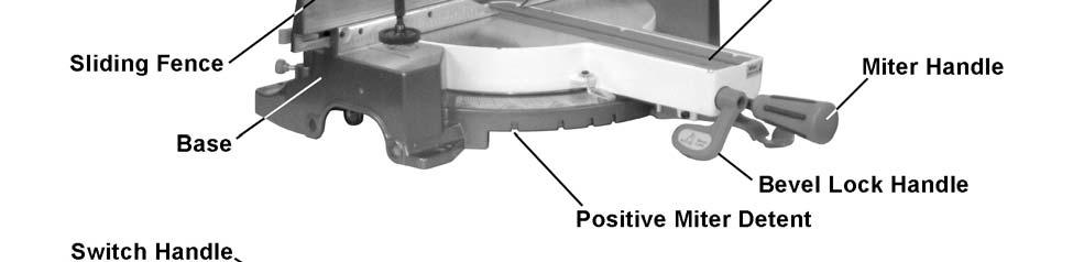

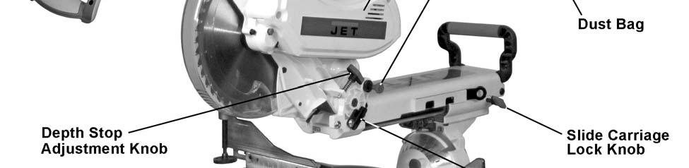
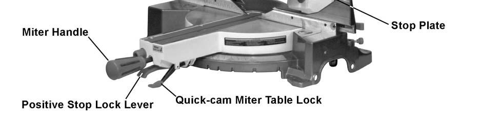
9 Features 9

10 Shipping Contents Unpacking 1. Remove the contents from the shipping container. 2. Compare the contents of the shipping container with the list found below. Make certain that all items are accounted for before discarding any packing material. Report any shortages or damage to your JET distributor. Contents of the Shipping Container A Compound Miter Saw (1) B Dust Bag (1) C Hold-down Clamp (1) D Lock Knob (2) -- Owner s Manual (1) -- Warranty Registration Card Tools Supplied for Assembly E Blade Wrench Tools not included 00Adjustable Wrench 006mm Hex Wrench 00Crosspoint Screwdriver 00Slotted Screwdriver 00Combination Wrench C D E Read and understand all assembly instructions before attempting assembly! Failure to comply may cause serious injury! Contents of Shipping Container Note: Optional work support extensions (stock no ) are available for your miter saw. Contact Walter Meier customer service to order. Assembly Unlocking the Slide Carriage Loosen the slide carriage lock knob (A). When transporting or storing the miter saw, the slide carriage (B) should always be locked in position. Figure 1 10
. 2. Pull out the hold-down latch (A, Fig. 2). 3. Raise the cutting head to the up position.")


 in a mounting hole located behind the right or left fence. 2. Thread the hold-down clamp knob (D) into the hole located at the rear of the saw base. 3.")
11 Releasing the Cutting Head When not in use, lock the cutting head in the down position. Failure to comply can cause serious injury or damage equipment. Unlocking 1. Push down on the switch handle (page 9). 2. Pull out the hold-down latch (A, Fig. 2). 3. Raise the cutting head to the up position. Locking Note: When not in use, lock the cutting head in the down position. 1. Push the cutting head down 2. Press the hold-down latch (A, Fig. 2) in to lock. Important: Always use the carrying handles when lifting or moving to avoid damage to the machine. Figure 2 Installing the Dust Bag 1. Squeeze the metal collar wings (B, Fig. 3) of the dust bag (A, Fig. 3). 2. Place the dust bag neck opening around the exhaust port (C, Fig. 3), and release the collar wings (B). To empty the dust bag, remove from exhaust port, open zipper on underside of bag and empty into waste container. Note: Check and empty bag frequently. Do not wait for it to get full. Figure 3 Installing the Safety Hold-down Clamp 1. Place the hold-down clamp assembly (A, Fig. 4) in a mounting hole located behind the right or left fence. 2. Thread the hold-down clamp knob (D) into the hole located at the rear of the saw base. 3. Tighten the hold-down clamp knob (D). Figure 4 Saw Blade Wrench For convenience, a storage clip (A, Fig. 5) is located on the right side of the sliding carriage for storing the blade wrench (B). Figure 5 11
12 Table Inserts Always unplug the saw to avoid accidental starting. Failure to comply may cause serious injury! Remove table insert to remove all small pieces of debris from the table cavity before performing any cuts. For portable use: Place the saw on a 3/4 in. thick piece of plywood and bolt the base securely to the plywood using the mounting holes on the base. Mounting hardware is not included and must be purchased separately. Use C-clamps to clamp this mounting board to a stable work surface at the worksite. Be sure to reattach the table insert prior to performing a cutting operation. Removing or Installing the Blade Do not start the saw without checking for interference between the blade and table insert. Damage could result to the blade, table insert or turntable if blade strike occurs during the cutting operation. To remove: 1. Loosen and remove six screws on the table inserts (see page 9) with a crosspoint screwdriver 2. Remove the inserts. To install: 3. Reposition the table inserts. 4. Install the six screws and tighten. Check for blade clearance by moving the slide carriage through the full motion of the blade in the table slot. Mounting the Saw Observe the following safety measures to avoid injury form unexpected saw movement: Disconnect the power cord and lock the cutting head in the lower position. Lock the slide carriage in place. When lifting: Use the carrying handles on the top of the saw. Bend at the knees, not from the back. Clamp or bolt the saw on a level work surface. Disconnect power and make sure the switch is in the OFF position to avoid accidental starts. Failure to comply may cause serious injury! Removing Blade Referring to Figure 6: 1. Unplug the saw from the outlet. 2. Raise the miter saw to the upright position. 3. Raise the lower clear plastic blade guard (A) to the uppermost position. 4. While holding the lower blade guard, loosen the cover plate screw (C) with a crosspoint screwdriver. 5. Rotate the cover plate (B) to expose the arbor bolt (H). 6. Place the blade wrench over the arbor bolt (H). 7. Locate the arbor lock (E) on the motor, below the belt cover (D). 8. Press the arbor lock, holding it in firmly while turning the blade clockwise. The arbor lock will then engage and lock the arbor. Continue to hold the arbor lock, while turning the wrench clockwise to loosen the arbor bolt. 9. Remove the arbor bolt (H), arbor collar (G), and blade (J). Do not remove the inner blade collar. 10. Raise the lower clear plastic blade guard (A) to the upright position to remove the blade. Note: Pay attention to the pieces removed, noting their position and direction they face. Wipe the blade collars clean of any sawdust before installing a new blade. For stationary use: Select a location for the saw, such as the top of a workbench, making sure to provide sufficient room for handling the workpiece. Secure the saw to the bench Mounting hardware is not included and must be purchased separately. 12
13 Installing Blade Important: This machine requires a 10-inch diameter blade. Unplug the miter saw before changing and/or installing the blade. Referring to Figure 6: 1. Install a 10-in. blade (J) with a 5/8 in. arbor making sure the rotation arrow on the blade matches the clockwise rotation arrow on the upper guard, and the blade teeth are pointing downward. 2. Place the arbor collar (G) against the blade and on the arbor. Thread the arbor bolt (H) on the arbor in a counterclockwise direction. Important: Make sure that the flat edge inside the blade collar opening is aligned with the flat edge on the arbor shaft. Also, the flat -side of the arbor collar (G) must be placed against the blade (J). 3. Place the blade wrench on the arbor bolt (H). 4. Press the arbor lock (E), holding it in firmly while turning the blade counterclockwise (opposite the cutting direction of the blade). When it engages, continue to press the arbor lock (E) in, while tightening the arbor bolt (H) securely. 5. Rotate the cover plate (B) back to its original position until the slot in the cover plate engages with the cover plate screw (C). While holding the lower blade guard (A) up as shown, tighten the screw (C) with a cross-point screwdriver. 6. Lower the retractable blade guard (A) and verify that the operation of the guard does not bind or stick. 7. Turn the blade to disengage the arbor lock (E); then verify that the blade will spin freely. Never use the saw without the cover plate securely in place. Failure to comply may cause serious injury! The cover plate keeps the arbor bolt from falling out if it accidentally loosens, and helps prevent the spinning blade from coming off the saw. Figure 6 Verify that the collars are clean and properly installed. Lower the blade into the table and verify that it does not come into contact with the metal base or the turn table. Failure to comply may cause serious injury! 13


14 Adjustments Before attempting any adjustments To avoid injury from unexpected starting or electrical shock make sure the trigger is released and remove the power cord from the power source. Failure to comply may cause serious injury! Note: Your miter saw was adjusted at the factory. However, during shipment slight misalignment may have occurred. Check the following settings and adjust if necessary prior to using this miter saw. Bevel Stop Adjustments 90 (0 ) Bevel Adjustment 1. Set the miter angle to 0. Note: A bevel angle of 0 corresponds to a bladeto-miter-table angle of Turn the bevel lock handle (A, Fig. 8) clockwise to loosen and tilt the cutting arm while pushing the bevel detent pin (E, Fig. 10) in against the 0 bevel stop. Turn the bevel lock handle (A, Fig. 8) counterclockwise to tighten. 3. Place a combination square on the miter table with the rule against the table and heel of the square against the saw blade. Figure 8 If the blade is not 0 to the miter table: 4. Using a 4mm hex wrench, loosen four adjustment screws (B, Fig. 9) at the back of the miter saw. Pull the bevel detent pin (E, Fig. 10) out fully. 5. Unlock the bevel lock handle (A, Fig. 8) and position the cutting arm to be zero degrees to the table using the combination square as your reference. 6. When the blade is at zero degrees to the table, turn the bevel lock handle (A, Fig. 8) clockwise to tighten. 7. Push in the bevel detent pin (E, Fig. 10). If the pin doesn t slide in, the anchor plate needs to be shifted. To do this, move the adjustment screws (B, Fig. 9) in their slots until the bevel detent pin slides in. 8. Now slide the adjustment screws (B, Fig. 9) until the anchor plate rests against the bevel detent pin. Tighten the four adjustment screws. (B, Fig. 9). Note: Use the screws to hold the anchor plate against the detent pin while tightening the screws, to prevent slack occurring during the tightening process. Figure 9 Figure 10 14

. 3. Adjust bevel indicators (D, Fig. 10) to the 0 mark on the bevel scale and retighten the screws (C, Fig. 10). Figure 11 45 Left Bevel Positive Stop Adjustment 1.")

15 9. Test the 90 alignment as follows: Unlock bevel lock handle (A, Fig. 8), and pull out bevel detent pin (E, Fig. 10). Rotate head left or right, push in bevel detent pin, and bring head back to vertical to contact the detent pin. Re-check blade with the square. If needed, repeat the above procedure to get accurate alignment. Bevel Scale Indicators 1. Set the blade to be exactly 90 (0 ) to the table. 2. With cross-point screwdriver, loosen two bevel indicator screws (C, Fig. 10). 3. Adjust bevel indicators (D, Fig. 10) to the 0 mark on the bevel scale and retighten the screws (C, Fig. 10). Figure Left Bevel Positive Stop Adjustment 1. Set the miter angle to zero degrees. Fully extend the sliding fence completely to the left then pull the bevel detent pin (E, Fig. 10) out. Note: When retracting the bevel detent pin, it may be required to slightly shift the upper arm assembly right or left. 2. Loosen the bevel lock handle (A, Fig. 8) and tilt the cutting arm completely to the left (Figure 11). 3. Using a combination square, check to see if the blade is 45 to the table. 4. To adjust, tilt the cutting arm to zero degrees, loosen the lock nut (B, Fig. 12) and turn the stop bolt (A, Fig. 12) in or out accordingly. Figure Tilt the cutting arm back to the left and recheck alignment. 6. Repeat steps 1 4 if necessary until the blade is 45 to the table, then tighten the lock nut (B, Fig. 12) to secure the stop bolt (A, Fig. 12). 45 Right Bevel Positive Stop Adjustment 1. Set the miter angle to zero degrees. Fully extend the sliding fence completely to the right then pull the bevel detent pin (E, Fig. 10) out. Note: When retracting the bevel detent pin, it may be required to slightly shift the upper arm assembly right or left. 2. Loosen the bevel lock handle (A, Fig. 8) and tilt the cutting arm completely to the right (Figure 13). 3. Using a combination square, check to see if the blade is 45 to the table. Figure To adjust, tilt the cutting arm to zero degrees, loosen the locknut (D, Fig. 12) and turn the stop bolt (C, Fig. 12) in or out accordingly. 5. Tilt the cutting arm back to the right and recheck alignment. 15
. 3. Tilt the cutting arm to the 33.")
 in or out with a 3mm hex wrench until the blade is 33.9 to the table. 6. Repeat steps for the right bevel 33.")
16 6. Repeat steps 1 4 if necessary until the blade is 45 to the table, then tighten the lock nut (D, Fig. 12) to secure the stop bolt (C, Fig. 12) Left & Right Bevel Adjustment 1. Set the miter angle to zero degree. Fully extend both sliding fences. 2. Loosen the bevel lock handle (A, Fig. 8). 3. Tilt the cutting arm to the 33.9 left bevel position and engage the positive stop by pushing the bevel detent pin (E, Fig. 12) in. 4. Using a combination square, check to see if the blade is 33.9 to the table. Figure To adjust, turn the setscrew (A, Fig. 14) in or out with a 3mm hex wrench until the blade is 33.9 to the table. 6. Repeat steps for the right bevel 33.9º bevel adjustment, making adjustments to setscrew B, Fig. 15. Miter Angle The sliding compound miter saw scale can be easily read, showing miter angles from 0 to 45 to the left, and 0 to 60 to the right. The miter saw table has ten of the most common angle settings with positive stops at 0, 15, 22.5, 31.6, and 45 left and right and 60 right. These positive stops position the blade at the desired angle quickly and accurately. Follow the process below for quickest and most accurate adjustments. Figure 15 Referring to Figure 16: 1. Lift up on the quick-cam miter table lock (A) to unlock the table. 2. Lift up on the positive stop locking lever (C) and move the turntable with handle (B) to align the indicator (D) to the desired degree measurement. 3. Lock the table into position by pressing down on the quick-cam miter table lock (A). Figure 16 Miter Scale Indicator Adjustment 4. Move the table to the 0 positive stop. 5. Loosen the screw (E) that holds the indicator with a screwdriver. 6. Adjust the indicator (D) to the 0 mark and retighten screw. 16
 and the ruler (C) against the fence (D). 4. Adjust the fence 90 to the blade and tighten the four fence locking screws.")

 up; at the same time grasp the miter handle (B) and rotate the miter table left or right to the desired angle. 3.")
17 Adjusting Fence Squareness 1. Loosen four fence locking screws (D, Fig. 18). Note: two locking screws to each fence. 2. Lower the cutting arm and lock in position. 3. Using a square, lay the heel (B, Fig. 17 of the square against the blade (A) and the ruler (C) against the fence (D). 4. Adjust the fence 90 to the blade and tighten the four fence locking screws. If the saw has not been used recently, recheck blade squareness to the fence and readjust if needed. 5. After fence has been aligned, using a scrap piece of wood, make a cut at 90º then check squareness on the piece. Readjust if necessary. Positive Stop Miter Angle Adjustment Referring to Figure 19: 1. Unlock the miter table by lifting up on the quickcam miter table lock (A). 2. Raise the positive stop locking lever (C) up; at the same time grasp the miter handle (B) and rotate the miter table left or right to the desired angle. 3. Release the positive stop locking lever (C) and set the miter at the desired angle making sure the lever snaps into place. Note: There are ten positive stops into which the lever will lock. 4. After the angle is selected, press down on the quick-cam miter table lock (A). Quick-cam Miter Table Lock Operation If a miter angle required is not one of ten positive stops, the miter table can be locked at any angle between these positive stops by using the quickcam miter table lock. Referring to Figure 19: 1. Unlock the miter table by lifting up on the quickcam miter table lock (A). 2. Raise the positive stop locking lever (C) up; at the same time grasp the miter handle (B) and rotate the miter table left or right to the desired angle. 3. Release the positive stop locking lever (C). 4. Press down on the quick-cam miter table lock (A) until it locks the miter table in place. Figure 17 Figure 18 Figure 19 17
 in the down position to lock. 2.")
 to verify that it locks the table securely into position. 4. Tighten the lock nut (D) to lock the miter locking mechanism into place.")
 until the teeth of the blade are at the desired depth. 4.")
18 Note: The quick-cam miter table lock should lock the table and prevent it from moving. If adjustment is needed, see Quick-cam Miter Table Lock Adjustment below. Quick-cam Miter Table Lock Adjustment Referring to Figure 19: 1. Place the quick-cam miter lock (A) in the down position to lock. 2. Loosen the lock nut (D) with a 13 mm wrench, then turn the stop nut (E) to extend the locking arm against the base of the miter saw. 3. Test the quick-cam miter lock (A) to verify that it locks the table securely into position. 4. Tighten the lock nut (D) to lock the miter locking mechanism into place. Presetting the Cutting Depth The depth of cut can be preset for even and repetitive shallow cuts. Referring to Figure 20: 1. Pull hold-down latch (C) out. 2. Flip the stop plate (A) counterclockwise to the left. 3. Adjust the cutting head down (See Cutting Head section) until the teeth of the blade are at the desired depth. 4. While maintaining the cutting head in the desired position, turn the stop knob (B) until it touches the stop plate (A). 5. Recheck the blade depth by moving the cutting head front to back through the full motion of a typical cut along the control arm. Rear Support Bar Figure 20 Figure 21 Do not operate the saw without the rear extension support bar. Failure to comply may result in serious injury! Loosen the two screws (A, Fig. 21) and extend the rear extension support bar (B, Fig. 21) by sliding it out, then tighten the two screws. Laser Beam The laser is turned on with a switch located on the saw handle (A, Fig. 22). When left on indefinitely, a sensor will turn the laser off after 20 minutes. The switch must be reset (turned off, then turned on again after 2 seconds) to restart. The laser has no adjustments and should not require adjustment. If adjustment should become necessary, take saw to an approved service center. Figure 22 18


19 Laser radiation. Avoid direct eye exposure. Always un-plug miter saw from power source before making any adjustments. Laser Warning Label: Max output <1mW DIODE LASER: nm, Complies with 21CFR and Finishing a cut 1. Hold the cutting arm in the down position. 2. Release trigger switch (A, Fig. 23) and wait for all moving parts to stop before moving your hands and raising the cutting arm. 3. If the blade does not stop within 10 seconds, unplug the saw and follow the instructions in the Troubleshooting section. If material becomes jammed 1. Release trigger switch. 2. Wait for all moving parts to stop. 3. Unplug the miter saw. Use of controls or adjustments or performance of procedures other than those specified in this manual may result in hazardous radiation exposure. The use of optical instruments with this product will increase eye hazard. Do not attempt to repair or disassemble the laser. If unqualified persons attempt to repair this laser product, serious injury may result. Any repair required on this laser product should be performed by authorized service center personnel. To Turn the Saw On Depress the trigger switch (A, Fig. 23). Note: Make the On/Off switch child-proof by inserting a padlock through the hole (B, Fig. 23) in the trigger switch. The miter saw is equipped with an automatic blade brake. When the trigger switch is released, the electric blade brake will stop the blade within approximately 10 seconds. Operation Before attempting any operation with your miter saw, make sure that you have read and thoroughly understand the warnings contained on pages 4-5 and the Compound Miter Saw Safety section on page 6. Failure to comply may result in serious injury! Starting a cut 1. Place hands at least 8-3/4 in. away from the path of the blade. 2. Hold workpiece firmly against the fence to prevent movement toward the blade. 3. Bring the saw blade down to the workpiece to see the cutting path of the blade. 4. Squeeze the trigger switch (A, Fig. 23) to start saw. 5. Lower blade into workpiece with a firm downward motion. Figure 23 19

 (shown locked in Figure 24) by pushing it toward the rear of the machine. 2. Extend the fence (B) by sliding it out (C) to ensure that the blade will clear the fence for degree of the bevel cut selected.")
20 Sliding Fence The sliding fence must be extended to the left or right when making bevel cuts. Failure to comply may cause serious injury! Failure to extend the sliding fence will not allow enough space for the blade to pass through. This could result in serious injury. At extreme miter or bevel angles the saw blade may also contact the fence resulting in damage to equipment as well as personal injury. To adjust the sliding fence (refer to Figure 24): 1. Unlock the fence cam locking lever (A) (shown locked in Figure 24) by pushing it toward the rear of the machine. 2. Extend the fence (B) by sliding it out (C) to ensure that the blade will clear the fence for degree of the bevel cut selected. Lock the fence cam locking lever (A) as shown. Note: Secure the sliding fence in position closest to the saw blade when transporting the saw. Figure 24 Sliding Carriage System To reduce the risk of injury, return carriage to the full rear position after each crosscut operation. For chop cutting operations on small workpieces, slide the cutting head assembly completely toward the rear of the unit and tighten the carriage lock knob (A, Fig. 25). To cut wide boards up to 12 in., the carriage lock knob (A, Fig. 25) should be loosened to allow the cutting head to slide freely. Figure 25 To avoid injury from materials being thrown, always unplug the saw to avoid accidental starting, and remove small pieces of material from the table cavity. The table insert may be removed for this purpose, but always reattach the table insert prior to performing a cutting operation. Miter Cut Referring to Figure 26: The sliding compound miter saw has ten positive miter stop detents (A) located on the saw base. The stops represent the following miter cut angles: 0, 15, 22.5, 31.6 and 45 degrees left and right, and 60 right. To make a miter cut: 1. Unlock the miter table by lifting up on the quickcam miter table lock (E). 20
, making sure the lever snaps into place at one of the miter stop detents (A).")
 to secure the table into position. If the miter angle desired is not one of the ten positive stops noted above: 5.")
21 2. Raise the positive stop locking lever (C) up, at the same time grasp the miter handle (D) and rotate the miter table left or right to the desired angle. 3. Release the positive stop locking lever (C), making sure the lever snaps into place at one of the miter stop detents (A). Note: The lever will only lock into place at one of the ten positive stops indicated above Once the desired miter angle is achieved: 4. Press down on the quick cam miter table lock (E) to secure the table into position. If the miter angle desired is not one of the ten positive stops noted above: 5. Simply lock the table at the desired angle by pressing down on the quick-cam miter table lock (E). Figure 26 Bevel Cut The sliding fence must be extended to the left or right when making bevel cuts. Failure to comply may cause serious injury! Failure to extend the sliding fence will not allow enough space for the blade to pass through. This could result in serious injury. At extreme miter or bevel angles the saw blade may also contact the fence resulting in damage to equipment as well as personal injury. Tilt the cutting head to the desired angle as shown on the bevel scale. The blade can be positioned at any angle, from a 90 straight cut (0 on the scale) to a 45 left and right bevel. Tighten the bevel lock handle (B, Fig. 26) by pushing down to lock the cutting head in position. Bevel positive stops are provided at 0, 33.9 and 45. Note: The saw comes with a 33.9 bevel detent pin for setting up crown molding cuts when the angle of the walls equals Bevel Detent Pin for Crown Moldings Note: A bevel detent pin is incorporated into this machine for quick bevel adjustments when the desired bevel angle is Referring to Figure 27 (except where indicated): 1. Push the bevel detent stop pin (E) in. 2. Loosen the bevel lock handle (A). 3. Rotate the cutting head (D, Fig. 28) until the bevel detent pin (E) stops the bevel angle at 33.9 on the bevel scale (F). 4. Tighten the bevel lock handle (A) before you make your cut. 21 Figure 27 Figure 28
. Setting the miter angle 4. Set the desired miter angle and lock into position. See Miter Cut. 5.")
22 Compound Cuts Referring to Figure 27: Setting the bevel angle 1. Extend the fence by sliding it out to the required location (see Sliding Fence on page 22). 2. Loosen the bevel lock handle (A). 3. Set the desired bevel angle; then lock the bevel lock handle (A). Setting the miter angle 4. Set the desired miter angle and lock into position. See Miter Cut. 5. Unlock the miter table by lifting up on the quickcam miter table lock (D). 6. Raise the positive stop locking lever (C) up, at the same time grasp the miter handle (B) and rotate the miter table left or right to the desired angle. 7. Release the positive stop locking lever (C). 8. Lock the miter table by pressing down on the quick-cam miter table lock (D). 90º Crosscut Narrow Boards For 90º crosscut operations on small workpieces (refer to Figure 29): 1. Slide the cutting head assembly completely toward the rear of the unit and tighten the carriage lock knob (F). 2. Position the cutting head to the 0 bevel position and lock the bevel lock handle (C). 3. Position the table to the 0 miter angle and lock the quick cam miter table lock (D). 4. Position the workpiece on the table and against the fence. Use a hold-down clamp (E) attached to the base, whenever possible. 5. Pull the trigger (A), turning on the saw. Lower the blade by pushing the handle (B) down into the workpiece with slow and even pressure. 6. When the cut is complete, release the switch and allow the blade to stop before raising the cutting head assembly. D Figure 29 22

23 Slide Cutting Wide Boards Observe the following precautions: Never pull the cutting head assembly and spinning blade toward you during the cut. Let the blade reach full speed before cutting. Extending the fence by sliding it out to the required location. Failure to comply may cause serious injury! Use this operation to crosscut boards up to 12 inches wide. Referring to Figure 30: 1. Unlock the carriage lock knob (D). 2. Set both the desired bevel angle and/or the miter angle as described in Compound Cuts (page 22); then lock into position. 3. If bevel cutting, set both the left and right sliding fences (C) to their proper location. 4. Use a hold down clamp to secure the workpiece. 5. Grasp the switch handle (F) and pull the carriage (A) forward until the center of the saw blade is over the front of the workpiece (B). 6. Pull the trigger (E) to turn the saw on. 7. When the saw reaches full speed, push the saw handle (F) down slowly, cutting through the leading edge of the workpiece. 8. Slowly move the saw handle (F) toward the fence (C) to complete the cut. 9. Release the trigger (E) and allow the blade to stop spinning before allowing the cutting head to raise. Figure 30 Cutting Bowed Material Always unplug the saw when removing small pieces of debris. Failure to comply may cause serious injury! Referring to Figure 31: 1. Position a curved workpiece (C) against the fence (B). 2. Secure the curved workpiece with a clamping device (A). Cutting a curved workpiece without the support of the fence and clamping device could result in personal injury. Figure 31 23
24 Rough Cutting a Dado 1. Mark lines identifying the width and depth of the desired cut on the workpiece and position on the table so the inside tip of the blade is positioned on the line. Use a hold down clamp to secure the workpiece. 2. Set the cutting depth as described in Presetting the Cutting Depth on page Lower the cutting head (the hold-down latch C, Fig. 32 must be in the out position as shown) so the tip of the blade touches the top surface workpiece at the marked line. 4. Cut two parallel grooves. Auxiliary Wood Fence When making multiple or repetitive cuts that result in cut-off pieces of one inch or less, it is possible for the saw blade to catch the cut-off piece and throw it out of the saw or into the blade guard and housing, possibly causing damage or injury. To minimize this, an auxiliary wood fence can be mounted to your saw. Holes are provided in the saw fence to attach an auxiliary wood fence (this provides additional depth of cut). This fence should be constructed of straight wood approximately 3/4 in. thick by 1-1/2 in. high by 22 in. long. Attach the wood fence securely and make a full depth cut to make a blade slot. Check for interference between the wood fence and the lower blade guard. Adjust if necessary. Cutting Base Molding Base moldings and many other moldings can be cut on a compound miter saw. The setup of the saw depends on molding characteristics and application. Perform practice cuts on scrap material to achieve best results: 1. Always make sure moldings rest firmly against fence and table. Use hold-down, crown molding vise or C-clamps, whenever possible, and place tape on the area being clamped to avoid marks. 2. Reduce splintering by taping the cut area prior to making the cut. Mark the cut line directly on the tape. 3. Splintering typically happens due to an incorrect blade application and thinness of the material. Note: Always perform a dry run cut so you can determine if the operation being attempted is possible before power is applied to the saw. Figure 32 Crown Molding Your compound miter saw is suited for the difficult task of cutting crown molding. To fit properly, crown molding must be compound-mitered with extreme accuracy. The two surfaces on a piece of crown molding that fit flat against the ceiling and wall are at angles that, when added together, equal exactly 90. Most crown molding has a top rear angle (the section that fits flat against the ceiling) of 52 and a bottom rear angle (the section that fits flat against the wall) of 38. In order to accurately cut crown molding for a 90 inside or outside corner, lay the molding with its broad back surface flat on the saw table. When setting the bevel and miter angles for compound miters, remember that the settings are interdependent; changing one changes the other, as well. Changing the Belt 1. Unplug your saw. 2. Loosen the bolts and remove the belt cover. 3. Turn the screw counterclockwise with a hex wrench to move the motor forward. 4. Remove and replace the belt. 5. Turn the screw clockwise with a hex wrench to move the motor back. Do not over tighten. 6. Replace the belt cover and tighten the bolts. 24
25 Bevel/Miter Settings Settings for standard crown molding lying flat on compound miter saw table. Note: The chart below references a compound cut for crown molding only when the angle between the walls equals 90. Type of Cut Key Bevel Setting Miter Setting Procedure Inside corner Left Side IL Right 1. Position top of molding against fence. 2. Miter table set at RIGHT LEFT side is finished piece. Inside corner Right Side Outside corner Left Side IR Left 1. Position bottom of molding against fence. 2. Miter table set at LEFT LEFT side is finished piece. OL Left 1. Position bottom of molding against fence. 2. Miter table set at LEFT RIGHT side is finished piece. Outside corner Right Side OR Right 1. Position top of molding against fence. 2. Miter table set at RIGHT RIGHT side is finished piece 25
26 Crown Molding Chart Compound miter saw miter and bevel angle settings, wall to crown molding angles Angle Between Walls 52/38º Crown Molding 45/45º Crown Molding 52/38º Crown Molding 45/45º Crown Molding 0Miter 0Setting 0Bevel 0Setting 0Miter 0Setting 0Bevel 0Setting Angle Between Walls 0Miter 0Setting 0Bevel 0Setting 0Miter 0Setting 0Bevel 0Setting
Operating Instructions and Parts Manual 12" Sliding Dual Bevel Compound Miter Saw Benchtop Series Model No. JMS-12SCMS
 Operating Instructions and Parts Manual 12" Sliding Dual Bevel Compound Miter Saw Benchtop Series Model No. JMS-12SCMS For serial no. 10070329 and higher JET 427 New Sanford Road LaVergne, Tennessee 37086
Operating Instructions and Parts Manual SR-2024M and SR-2236M Slip Rolls
 Operating Instructions and Parts Manual SR-2024M and SR-2236M Slip Rolls JET 427 New Sanford Road LaVergne, Tennessee 37086 Part No. M-756020 Revision A1 05/2014 Copyright 2014 JET Warranty and Service
Assembly Instructions and Parts Manual 5C Collet Closer for GHW Lathes Model CC-GHW
 Assembly Instructions and Parts Manual 5C Collet Closer for GHW Lathes Model CC-GHW JET 427 New Sanford Road LaVergne, Tennessee 37086 Part No. M-321519 Ph.: 800-274-6848 Revision G1 03/2014 www.jettools.com
Operating Instructions and Parts Manual 5C Collet Closer for GHB-1340A Lathe Model CC-GHB1340A
 Operating Instructions and Parts Manual 5C Collet Closer for GHB-1340A Lathe Model CC-GHB1340A JET 427 New Sanford Road LaVergne, Tennessee 37086 Part No. M-321514A Ph.: 800-274-6848 Revision C 03/2014
Assembly Instructions and Parts Manual 5C Collet Closer for ZX Series Lathes Model CC-ZX
 Assembly Instructions and Parts Manual 5C Collet Closer for ZX Series Lathes Model CC-ZX JET 427 New Sanford Road LaVergne, Tennessee 37086 Part No. M-321292 Ph.: 800-274-6848 Revision B 03/2014 www.jettools.com
Operating Instructions and Parts Manual 10" Sliding Dual Bevel Compound Miter Saw Benchtop Series Model No. JMS-10SCMS
 Operating Instructions and Parts Manual 10" Sliding Dual Bevel Compound Miter Saw Benchtop Series Model No. JMS-10SCMS R C US 174315 WALTER MEIER (Manufacturing) Inc. 427 New Sanford Road LaVergne, Tennessee
Operating Instructions and Parts Manual Sliding Table Jig
 Operating Instructions and Parts Manual Sliding Table Jig WMH TOOL GROUP 2420 Vantage Drive Elgin, Illinois 60123 Part No. M-709695 Ph.: 800-274-6848 Revision A 04/04 www.wmhtoolgroup.com Copyright WMH
Assembly Instructions and Parts Manual JPSF-1 Fence and JPSR Rail Set #
 Assembly Instructions and Parts Manual JPSF-1 Fence and JPSR Rail Set #1002493 JET 427 New Sanford Road LaVergne, Tennessee 37086 Part No. M-708482 Ph.: 800-274-6848 Revision C3 02/2014 www.jettools.com
Operating Instructions and Parts Manual Foot Shear Models: FS-1636H, FS-1652H
 Operating Instructions and Parts Manual Foot Shear Models: FS-1636H, FS-1652H JET 427 New Sanford Road LaVergne, Tennessee 37086 Part No. M-752636 Ph.: 800-274-6848 Revision B2 08/2014 www.jettools.com
Operating Instructions and Parts Manual HN-16T Hand Notcher
 Operating Instructions and Parts Manual HN-16T Hand Notcher JET 427 New Sanford Road LaVergne, Tennessee 37086 Part No. M-756016 Ph.: 800-274-6848 Revision B1 08/2018 www.jettools.com Copyright 2015 JET
Operating Instructions and Parts Manual Box and Pan Brake Models: BP-1648H, BP-2248H
 Operating Instructions and Parts Manual Box and Pan Brake Models: BP-18H, BP-2248H JET 427 New Sanford Road LaVergne, Tennessee 37086 Part No. M-752116 Ph.: 800-274-6848 Revision B 06/2014 www.jettools.com
Assembly Instructions and Parts Manual Taper Attachment for Bench Lathes Model TAK-13GH/BD
 Assembly Instructions and Parts Manual Taper Attachment for Bench Lathes Model TAK-13GH/BD JET 427 New Sanford Road LaVergne, Tennessee 37086 Part No. M-321442 Ph.: 800-274-6848 Revision B 03/2014 www.jettools.com
Operating Instructions and Parts Manual SLT-1100 Jumbo Scissor Lift Table
 Operating Instructions and Parts Manual SLT-1100 Jumbo Scissor Lift Table JET 427 New Sanford Road LaVergne, Tennessee 37086 Part No. M-140780 Ph.: 800-274-6848 Revision B1 05/2014 www.jettools.com Copyright
Owner's Manual XACTA Fence II Commercial 30/50
 Owner's Manual XACTA Fence II Commercial 30/50 JET 427 New Sanford Road LaVergne, Tennessee 37086 Part No. M-708950Z Ph.: 800-274-6848 Revision L 10/2014 www.jettools.com Copyright 2014 JET Warranty and
Operating Instructions and Parts Manual SR-1650M Slip Roll
 Operating Instructions and Parts Manual SR-1650M Slip Roll WALTER MEIER (Manufacturing) Inc. 427 New Sanford Road LaVergne, Tennessee 37086 Part No. M-756050 Ph.: 800-274-6848 Revision A 12/2010 www.waltermeier.com
XACTA Commercial Fence & Rails (50 Rip) for JTAS-12-DX Table Saw
 for JTAS-12-DX Table Saw") Assembly Instructions and Parts Manual XACTA Commercial Fence & Rails (50 Rip) for JTAS-12-DX Table Saw WALTER MEIER (Manufacturing) Inc. 427 New Sanford Road LaVergne, Tennessee 37086 Part No. M-708955Z
Assembly Instructions and Parts Manual XACTA Commercial Fence & Rails (50 Rip) for JTAS-12-DX Table Saw WALTER MEIER (Manufacturing) Inc. 427 New Sanford Road LaVergne, Tennessee 37086 Part No. M-708955Z
ALL RIGHTS RESERVED BY KING CANADA TOOLS INC.
 INDUSTRIAL RIP FENCE SYSTEM MODELS KRF-10/30L12-30 CONTRACTOR SAWS KRF-10/52L12-52 CONTRACTOR SAWS KRF-100/T50L12-50 CABINET SAWS INSTRUCTION MANUAL COPYRIGHT C 2000 ALL RIGHTS RESERVED BY KING CANADA
Operating Instructions and Parts Manual Tenoning Jig Model: JTG-10Q
 Operating Instructions and Parts Manual Tenoning Jig Model: JTG-10Q WALTER MEIER (Manufacturing) Inc. 427 New Sanford Road LaVergne, Tennessee 37086 Part No. M-708295 Ph.: 800-274-6848 Revision A1 06/2011
All Terrain Vise # 10010
 Operating Instructions & Service Parts Manual All Terrain Vise # 10010 Record purchase information for quick reference: WILTON 427 New Sanford Road LaVergne, Tennessee 37086 Ph.: 800-274-6848 www.wiltontools.com
Operating Instructions and Parts Manual Accu-Fence and Rail System for 64A, 64B and PM1000 Table Saws
 Operating Instructions and Parts Manual Accu-Fence and Rail System for 64A, 64B and PM1000 Table Saws Powermatic 427 New Sanford Road LaVergne, Tennessee 37086 Part No. M-2195075Z Ph.: 800-274-6848 Revision
Operating Instructions and Parts Manual 10" Compound Miter Saw Benchtop Series Model No. JMS-10CMS
 Operating Instructions and Parts Manual 10" Compound Miter Saw Benchtop Series Model No. JMS-10CMS R C US 174315 WALTER MEIER (Manufacturing) Inc. 427 New Sanford Road LaVergne, Tennessee 37086 Part No.
Operating Instructions and Parts Manual Tenoning Jig Model: JTG-10Q
 This Manual is Bookmarked Operating Instructions and Parts Manual Tenoning Jig Model: JTG-10Q WMH TOOL GROUP 2420 Vantage Drive Elgin, Illinois 60123 Part No. M-708295 Ph.: 800-274-6848 Revision A 10/04
VARIABLE SPEED WOOD LATHE
 MODEL MC1100B VARIABLE SPEED WOOD LATHE INSTRUCTION MANUAL Please read and fully understand the instructions in this manual before operation. Keep this manual safe for future reference. Version: 2015.02.02
KING CANADA INSTRUCTION MANUAL 10 COMPOUND SLIDING MITER SAW WITH TWIN LASER GUIDE MODEL: 8380
 KING CANADA 10 COMPOUND SLIDING MITER SAW WITH TWIN LASER GUIDE *Enhanced Twin Laser Effect MODEL: 8380 INSTRUCTION MANUAL COPYRIGHT 2008 ALL RIGHTS RESERVED BY KING CANADA TOOLS INC. WARRANTY INFORMATION
PS /8 Inch Electric Drill Assembly & Operating Instructions
 PS07216 3/8 Inch Electric Drill Assembly & Operating Instructions READ ALL INSTRUCTIONS AND WARNINGS BEFORE USING THIS PRODUCT. This manual provides important information on proper operation & maintenance.
OWNER'S MANUAL HN-16T Hand Notcher
 OWNER'S MANUAL HN-16T Hand Notcher WALTER MEIER (Manufacturing) Inc. 427 New Sanford Road LaVergne, Tennessee 37086 Part No. M-756016 Ph.: 800-274-6848 Revision A 04/2011 www.waltermeier.com Copyright
BB Inch Double Cut Saw Assembly & Operating Instructions READ ALL INSTRUCTIONS AND WARNINGS BEFORE USING THIS PRODUCT.
 BB07552 5 Inch Double Cut Saw Assembly & Operating Instructions READ ALL INSTRUCTIONS AND WARNINGS BEFORE USING THIS PRODUCT. This manual provides important information on proper operation & maintenance.
20 Log Splitter (Model C)
") INSTRUCTION MANUAL 20 Log Splitter (Model 38-610C) Dated 12-15-01 Part No. 1235600 Copyright 2001 Delta Machinery A Pentair Company To learn more about DELTA MACHINERY visit our website at: www.deltamachinery.com.
INSTRUCTION MANUAL 20 Log Splitter (Model 38-610C) Dated 12-15-01 Part No. 1235600 Copyright 2001 Delta Machinery A Pentair Company To learn more about DELTA MACHINERY visit our website at: www.deltamachinery.com.
Impact Wrench. 19 mm (3/4 ) MODEL 6906
 MODEL 6906") Impact Wrench 9 mm (3/4 ) MODEL 6906 002290 DOUBLE INSULATION I N S T R U C T I O N M A N U A L WARNING: For your personal safety, READ and UNDERSTAND before using. SAVE THESE INSTRUCTIONS FOR FUTURE REFERENCE.
Impact Wrench 9 mm (3/4 ) MODEL 6906 002290 DOUBLE INSULATION I N S T R U C T I O N M A N U A L WARNING: For your personal safety, READ and UNDERSTAND before using. SAVE THESE INSTRUCTIONS FOR FUTURE REFERENCE.
Assembly Instructions and Parts Manual Taper Attachment for ZH Lathes
 Assembly Instructions and Parts Manual Taper Attachment for ZH Lathes JET 427 New Sanford Road LaVergne, Tennessee 37086 Part No. M-321293 Ph.: 800-274-6848 Rev B 08/2018 www.jettools.com Copyright 2017
Assembly Instructions and Parts Manual JPSF-1 Fence and JPSR Rail Set
 Assembly Instructions and Parts Manual JPSF-1 Fence and JPSR Rail Set WALTER MEIER (Manufacturing) Inc. 427 New Sanford Road LaVergne, Tennessee 37086 Part No. M-708482 Ph.: 800-274-6848 Revision C2 02/2013
FREUD. Operating Instructions. JS104K Biscuit Joiner Kit
 FREUD Operating Instructions JS104K Biscuit Joiner Kit Contents Safety General Safety Rules Additional Safety Rules for Biscuit Joiners Functional Description and Specifications Symbols Parts and Feature
 GENERAL OPERATIONAL PRECAUTIONS WARNING! When using electric tools, basic safety precautions should always be followed to reduce the risk of fire, electric shock and personal injury, including the following.
WARNING! Read and understand the entire instruction manual before attempting set-up or operation of this machine!
 ! WARNING! Read and understand the entire instruction manual before attempting set-up or operation of this machine! 1. This machine is designed and intended for use by properly trained and experienced
12 DUAL BEVEL SLIDING COMPOUND MITER SAW WITH TWIN LASER GUIDE MODEL: 8390N INSTRUCTION MANUAL
 KING CANADA 12 DUAL BEVEL SLIDING COMPOUND MITER SAW WITH TWIN LASER GUIDE 09/2013 *Enhanced Twin Laser Effect MODEL: 8390N INSTRUCTION MANUAL COPYRIGHT 2013 ALL RIGHTS RESERVED BY KING CANADA TOOLS INC.
1/4 Sheet Palm Sander
 OWNER S MANUAL Model Number: PS160CA-3 1/4 Sheet Palm Sander TM Registration Card Inside CAUTION! To reduce the risk of fire, electric shock and personal injury, read and understand the owner s manual
3-1/4 HP VARIABLE SPEED PLUNGE ROUTER
 IMPORTANT INFORMATION 2-YEAR LIMITED WARRANTY FOR THIS PLUNGE ROUTER KING CANADA TOOLS OFFERS A 2-YEAR LIMITED WARANTY FOR NON-COMMERCIAL USE. 3-1/4 HP VARIABLE SPEED PLUNGE ROUTER PROOF OF PURCHASE Please
COJSAWBX Electric Jig Saw Assembly & Operating Instructions
 COJSAWBX Electric Jig Saw Assembly & Operating Instructions READ ALL INSTRUCTIONS AND WARNINGS BEFORE USING THIS PRODUCT. This manual provides important information on proper operation and maintenance.
Operating Instructions and Parts Manual Box and Pan Brake Model: BP-1248H
 Operating Instructions and Parts Manual Box and Pan Brake Model: BP-1248H WALTER MEIER (Manufacturing) Inc. 427 New Sanford Road LaVergne, Tennessee 37086 Part No. M-754100 Ph.: 800-274-6848 Revision C
ROTARY HAMMER OWNER'S MANUAL
 ROTARY HAMMER OWNER'S MANUAL WARNING: Read carefully and understand all INSTRUCTIONS before operating. Failure to follow the safety rules and other basic safety precautions may result in serious personal
Instruction Manual. Manual de instrucciones. Guide d utilisation ET PMET Rev 808
 Instruction Manual Manual de instrucciones Guide d utilisation ET2025 PMET2025-8 Rev 808 www.arrowfastener.com GENERAL SAFETY RULES WARNING! Read all instructions. Failure to follow all instructions listed
20 TON HyDRAULIC SHOP PRESS with GRID GUARD 06/2015 INSTRUCTION MANUAL MODEL: KHP-20T-GG COPYRIGHT 2015 ALL RIGHTS RESERVED BY KING CANADA TOOLS INC.
 06/2015 20 TON HyDRAULIC SHOP PRESS with GRID GUARD MODEL: KHP-20T-GG INSTRUCTION MANUAL COPYRIGHT 2015 ALL RIGHTS RESERVED BY KING CANADA TOOLS INC. warranty INFORMATION 2-yEAR LIMITED WARRANTY FOR THIS
INSTRUCTION BOOKLET AND WARRANTY INFORMATION 6 BENCH GRINDER
 INSTRUCTION BOOKLET AND WARRANTY INFORMATION 6 BENCH GRINDER Part No.: SW1250 PLEASE READ CARE AND SAFETY INSTRUCTIONS BEFORE USE SPECIFICATIONS Part No.: SW1250 Input Voltage: 240V Frequency: 50Hz Rated
VARIABLE SPEED WOOD LATHE. Model DB900 INSTRUCTION MANUAL
 VARIABLE SPEED WOOD LATHE Model DB900 INSTRUCTION MANUAL 1007 TABLE OF CONTENTS SECTION...PAGE Technical data.. 1 General safety rules....1-3 Specific safety rules for wood lathe.....3 Electrical information.4
Sander. Finishing INSTRUCTION MANUAL. MODEL BO4550 MODEL BO45502 Without dust bag and punch plate DOUBLE INSULATION SPEC IF1 CAT1 ONS.
 Finishing INSTRUCTION MANUAL Sander MODEL BO4550 MODEL BO4550 Without dust bag and punch plate DOUBLE INSULATION SPEC IF CAT ONS Pad size No load speed lopml Dimensions (L x W x H) Net weight mmxloomm
Home Workshop System WARNING. MARK V Model 500. Summary Manual. Designed and Built in Dayton, Ohio.
 Shopsmith Mark V Home Workshop System MARK V Model 500 Summary Manual Designed and Built in Dayton, Ohio. WARNING Read the SAFETY information in the Introduction section and complete the ASSEMBLY AND ALIGNMENT
OPERATOR'S MANUAL ROUTER MOUNTING KIT
 OPERATOR'S MANUAL MOUNTING KIT 4950301 (FOR USE WITH BT3000 AND BT3100 TABLE SAWS) Your new router mounting kit has been engineered and manufactured to Ryobi's high standard for dependability, ease of
All Terrain Vise # 10010
 Operating Instructions & Service Parts Manual All Terrain Vise # 10010 Record purchase information for quick reference: WALTER MEIER (Manufacturing) Inc. 427 New Sanford Road LaVergne, Tennessee 37086
Operating Instructions and Parts Manual Benchtop Oscillating Spindle Sander Model JBOS-5
 Operating Instructions and Parts Manual Benchtop Oscillating Spindle Sander Model JBOS-5 For models with serial no. 11095097 and higher JET 427 New Sanford Road Part No. M-708404 LaVergne, Tennessee 37086
SAFETY AND OPERATING MANUAL
 SAFETY AND OPERATING MANUAL BladeRunner X2 WX572 9 10 8 11 5 7 12 6 20 1 2 4 3 14 13 15 A2 A1 17 18 B2 B1 1 2 1 2 19 B3 3 4 2 C 1 D1 D1 C 2 1 E1 D2 1 2 E2 1 2 F G1 G1 F OFF ON G2 G3 H1 H2 I1 I2 I1 I2 J
01950 Heavy Duty Floor Standing Morticer with Cabinet
 Please dispose of packaging for the product in a responsible manner. It is suitable for recycling. Help to protect the environment, take the packaging to the local amenity tip and place into the appropriate
HAND HELD SAW W MILL
 HAND HELD SAW W MILL 92247 ASSEMBLY AND OPERATING INSTRUCTIONS 3491 Mission Oaks Blvd., Camarillo, CA 93011 Visit our Web site at http://www.harborfreight.com Copyright 2004 by Harbor Freight Tools. All
Cyclone Upcut Cut off saw
 Cyclone Upcut Cut off saw Operation manual WARNING The operator must thoroughly read and understand this manual before operating the cut off saw or starting any servicing. All safety and warning instructions
Operating Instructions and Parts Manual 16 ga. x 100 in. Box and Pan Brake Model BPF-16100
 Operating Instructions and Parts Manual 16 ga. x 100 in. Box and Pan Brake Model BPF-16100 JET 427 New Sanford Road LaVergne, Tennessee 37086 Part No. M-754115 Ph.: 800-274-6848 Edition 3 08/2018 www.jettools.com
Assembly Instructions and Parts Manual Fence and Rail Set for ProShop II Saw
 Assembly Instructions and Parts Manual Fence and Rail Set for ProShop II Saw Fits all JET ProShop, ProShop II, and JTAS-10 Table Saws JET 427 New Sanford Road LaVergne, Tennessee 37086 Part No. M-725005
10 Multi-Slide Miter Saw OWNER S MANUAL
 10 Multi-Slide Miter Saw OWNER S MANUAL WARNING: Read carefully and understand all ASSEMBLY AND OPERATION INSTRUCTIONS before operating. Failure to follow the safety rules and other basic safety precautions
Operator s Manual CAUTION: Customer Help Line
 Operator s Manual 2.5 HP (Max. Developed) 10 Blade 4800 R.P.M. COMPOUND MITER SAW With Laser Trac Model 137.212140 CAUTION: Before using this Miter Saw, read this manual and follow all its Safety Rules
18 GAUGE ELECTRIC METAL SHEAR
 241-9895 18 GAUGE ELECTRIC METAL SHEAR Operator s Manual SAVE THIS MANUAL You will need this manual for safety instructions, operating procedures and warranty. Put it and the original sales receipt in
Operator s Manual. 10 in. COMPOUND MITER SAW WITH LASER TRAC Model No
 Operator s Manual 0 in. COMPOUND MITER SAW WITH LASER TRAC Model No. 37.360 CAUTION: Before using this Miter Saw, read this manual and follow all its Safety Rules and Operating Instructions Safety Instructions
OWNER'S MANUAL JST-48 Sliding Table
 OWNER'S MANUAL JST-48 Sliding Table (shown mounted on JET 708663PK) JET EQUIPMENT & TOOLS, INC. P.O. BOX 1349 Phone:253-351-6000 A WMH Company Auburn, WA 98071-1349 Fax: 1-800-274-6840 www.jettools.com
Operating Instructions and Parts Manual 3/4, 1-1/2, and 3 Ton Grip Pullers Models JG-75A, JG-150A, JG-300A
 Operating Instructions and Parts Manual 3/4, 1-1/2, and 3 Ton Grip Pullers Models JG-75A, JG-150A, JG-300A Model JG-75A shown JET 427 New Sanford Road LaVergne, Tennessee 37086 Part No. M-286575 Ph.: 800-274-6848
Hinge Boring/Insertion Machine Set Up And Operation Instructions
 Hinge Boring/Insertion Machine Set Up And Operation Instructions Manufactured In The USA By: Thompson Industries, Inc. 1018 Crosby Avenue, Sycamore, IL. 60178-0127 Ph:815-899-6670 Fax:815-899-1918 Thank
Owner's Manual Box and Pan Brake Models: BP-1648H, BP-2248H
 This Manual is Bookmarked Owner's Manual Box and Pan Brake Models: BP-1648H, BP-2248H WMH TOOL GROUP 2420 Vantage Drive Elgin, Illinois 60123 Part No. M-752116 Ph.: 800-274-6848 Revision A1 08/04 www.wmhtoolgroup.com
154570/220 5/17/02 1:41 PM Page 3. Instruction Manual Variable Speed Orbital Action Jig Saw
 154570/220 5/17/02 1:41 PM Page 3 Instruction Manual 3157-220 Variable Speed Orbital Action Jig Saw 154570/220 5/17/02 1:41 PM Page 4 Getting the most out of your tool. Please take time to read this manual
10 IN. SLIDING COMPOUND MITER SAW WITH LASER TRAC Model No
 Operator s Manual 0 IN. SLIDING COMPOUND MITER SAW WITH LASER TRAC Model No. 37.22372 CAUTION: Before using this Miter Saw, read this manual and follow all its Safety Rules and Operating Instructions For
Tapping Screw (W/Flange) 46 Cord Armor 47 Tube (D) 48 Cord. 45 Cord Clip. Tapping Screw (W/Flange) 10 Gear Cover Ass'y. 12 Socket (B) Ass'y
 46 Cord Armor 47 Tube (D) 48 Cord. 45 Cord Clip. Tapping Screw (W/Flange) 10 Gear Cover Ass'y. 12 Socket (B) Ass'y") W8VB The exploded assembly drawing should be used only for authoized service center. W8VB Item No. Part time 1 Magnetic Hex. Socket 2 Sub Stopper 3 O-Ring (S-16) 4 Locator (A) 5 Lock Sleeve (A) 6 O-Ring
W8VB The exploded assembly drawing should be used only for authoized service center. W8VB Item No. Part time 1 Magnetic Hex. Socket 2 Sub Stopper 3 O-Ring (S-16) 4 Locator (A) 5 Lock Sleeve (A) 6 O-Ring
GENERAL OPERATIONAL PRECAUTIONS
 GENERAL OPERATIONAL PRECAUTIONS WARNING! When using electric tools, basic safety precautions should always be followed to reduce the risk of fire, electric shock and personal injury, including the following.
Trautman Carvers. Product Manual
 Trautman Carvers Product Manual Contents Product Specifications.... 4 Operating Precautions.... 6 Floor Carver Use.... 7 Floor Carver Diagram.... 10 Trautman Motor Lift Assist.... 11 Use of the Lift Assist....
Circular Saw MODEL MT581. WARNING: For your personal safety, READ and UNDERSTAND before using. SAVE THESE INSTRUCTIONS FOR FUTURE REFERENCE.
 ENGLISH Circular Saw MODEL MT58 005337 DOUBLE INSULATION I N S T R U C T I O N M A N U A L WARNING: For your personal safety, READ and UNDERSTAND before using. SAVE THESE INSTRUCTIONS FOR FUTURE REFERENCE.
10 15 AMP COMPOUND MITER SAW Operator s Manual
 240-2099 10 15 AMP COMPOUND MITER SAW Operator s Manual Save This Manual You will need this manual for safety instructions, operating procedures and warranty. Place it and the original sales receipt in
8" Bench Grinder OWNER S MANUAL SAFETY GLASSES C US E LISTED TABLE OF CONTENTS SPECIFICATIONS PLEASE WEAR. Stock Number W50058
 8" Bench Grinder Stock Number W50058 OWNER S MANUAL C US E154499 LISTED TABLE OF CONTENTS Safety Instructions...2 Bench Grinder Safety...3 Electrical Requirements...3 Replacement Parts List...4 Bench Grinder
Jig Saw Instruction Manual
 Power Glide Limited Warranty Consumer Power Tools for Home Use to Original Buyer World Factory, Inc. (Seller) warrants to the original Buyer only, that each POWER GLIDE power tool will be free from defects
Introduction to Carpentry Power Tools
 Youth Explore Trades Skills Introduction to Carpentry Power Tools Description s use power tools every day, and the ability to use these tools correctly and safely is paramount. In this Activity Plan, students
Operator s Manual. 12 IN. DUAL BEVEL COMPOUND MITER SAW WITH LASER TRAC Model No CAUTION:
 Operator s Manual IN. DUAL BEVEL COMPOUND MITER SAW WITH LASER TRAC Model No. 37.375640 CAUTION: Before using this Miter Saw, read this manual and follow all its Safety Rules and Operating Instructions
PRODUCT MANUAL 5-IN-1 MITER SAW STATION *SAVE THIS MANUAL FOR FUTURE REFERENCE
 PRODUCT MANUAL 5-IN-1 MITER SAW STATION *SAVE THIS MANUAL FOR FUTURE REFERENCE 92778 1 GENERAL SAFETY INFORMATION For your safety, please read these instructions carefully before use and keep them in the
Impakt Tools. Portable Pocket Hole Jig Model P1. Instruction Manual
 Impakt Tools Portable Pocket Hole Jig Model P1 Instruction Manual Introduction Congratulations on your purchase of the Impakt Tools P1 Portable Pocket-Hole Jig. Owning an Impakt Tools Pocket-Hole jig will
Operator s Manual. 10 in. MiterMate MITER SAW WITH LASER TRAC Model No CAUTION: Customer Help Line For Technical Support
 Operator s Manual 10 in. MiterMate MITER SAW WITH LASER TRAC Model No. 137.212260 CAUTION: Before using this Miter Saw, read this manual and follow all its Safety Rules and Operating Instructions Customer
Operating Instructions and Parts Manual 72-inch Box and Pan Brakes Models BP-1272 and BP-1672
 Operating Instructions and Parts Manual 72-inch Box and Pan Brakes Models BP-1272 and BP-1672 JET 427 New Sanford Road LaVergne, Tennessee 37086 Part No. M-754125 Ph.: 800-274-6848 Edition 3 08/2018 www.jettools.com
Agricultural Mechanics and Technology Power Tool Safety Rules
 Agricultural Mechanics and Technology Power Tool Safety Rules Name: BAND SAW Use: Cutting curves, circles and irregular shapes. 1. Use clean SHARP blades. 2. The teeth should always point DOWN. 3. Adjust
Mortising Attachment
 Mortising Attachment Owner s Manual WARNING: Read carefully and understand all ASSEMBLY AND OPERATION INSTRUCTIONS before operating. Failure to follow the safety rules and other basic safety precautions
L A M I N AT E F L O O R C U T T E R OWNER S MANUAL
 L A M I N AT E F L O O R C U T T E R OWNER S MANUAL WARNING: Read carefully and understand all INSTRUCTIONS before operating. Failure to follow the safety rules and other basic safety precautions may result
6 in. Bench Grinder with Worklight
 6 in. Bench Grinder with Worklight W50001 OWNER S MANUAL SAVE THIS MANUAL Table of Contents Safety Instructions 2 Bench Grinder Safety 3 Electrical Requirements 3 Replacement Parts List 4 Bench Grinder
7-1/4 IN. SLIDING COMPOUND MITER SAW WITH LASER TRAC Model No
 Operator s Manual 7-1/4 IN. SLIDING COMPOUND MITER SAW WITH LASER TRAC Model No. 137.322860 CAUTION: Before using this Miter Saw, read this manual and follow all its Safety Rules and Operating Instructions
MODEL SETUP & OPERATION MANUAL DOVETAIL JIG FEATURES SPECIFICATIONS
 SETUP & OPERATION MANUAL FEATURES Male and female dovetail joints are cut simultaneously, to ensure perfectly matched dovetail joints. Side stops provided, allow repeated precise dovetail joint cutting
12mm (Max) 6mm (Max) 82mm (Max) 12mm (Max) 6mm (Max)
 6mm (Max) 82mm (Max) 12mm (Max) 6mm (Max)") 1 1 2 2 3 3 82mm (Max) 12mm (Max) 12mm (Max) 6mm (Max) 4 4 5 6 8 6mm (Max) 0.5 0mm 1 5 6 7 7 8 9 9 A = B 10 11 12 D B 1 13 14 15 0 C A D E 16 17 18 F G D B N H J G I K 19 A 20 G L 21 C K 1mm L M 1mm 22
1 1 2 2 3 3 82mm (Max) 12mm (Max) 12mm (Max) 6mm (Max) 4 4 5 6 8 6mm (Max) 0.5 0mm 1 5 6 7 7 8 9 9 A = B 10 11 12 D B 1 13 14 15 0 C A D E 16 17 18 F G D B N H J G I K 19 A 20 G L 21 C K 1mm L M 1mm 22
Operator s Manual. 7-1/4 IN. COMPACT SLIDE MITER SAW WITH LASER TRAC Model No CAUTION:
 Operator s Manual 7-/4 IN. COMPACT SLIDE MITER SAW WITH LASER TRAC Model No. 37.322850 CAUTION: Before using this Miter Saw, read this manual and follow all its Safety Rules and Operating Instructions
# x 12 Wood Turner s Lathe
 #86892 8 x 12 Wood Turner s Lathe Please read and understand all instructions before using this tool. Note: These instructions will show you how to assemble this machine, work its controls and maintain
GENERAL OPERATIONAL PRECAUTIONS
 GENERAL OPERATIONAL PRECAUTIONS WARNING! When using electric tools, basic safety precautions should always be followed to reduce the risk of fire, electric shock and personal injury, including the following.
Instruction Manual For Baldor Polishing Lathes
 No. 276M Replaces 276L LB7009 Instruction Manual For Baldor Polishing Lathes SAFETY NOTICE: WARNING statements describe conditions that may lead to personnel injury including potentially fatal injuries
18 PIECE HOLE SAW SET
 18 PIECE HOLE SAW SET 94665 ASSEMBLY AND OPERATING INSTRUCTIONS Due to continuing improvements, actual product may differ slightly from the product described herein. 3491 Mission Oaks Blvd., Camarillo,
THIS ACCESSORY CAN ONLY BE USED ON THE
 Instruction Manual NOVA COMET II STAND THIS MANUAL CONTAINS IMPORTANT INFORMATION REGARDING SAFETY, OPERATION, MAINTENANCE AND STORAGE OF THIS PRODUCT. BEFORE USE, READ CAREFULLY AND UNDERSTAND ALL CAUTIONS,
RIGHT ANGLE DRILL ATTACHMENT WITH 3/8 KEYLESS CHUCK
 RIGHT ANGLE DRILL ATTACHMENT WITH 3/8 KEYLESS CHUCK 96996 ASSEMBLY AND OPERATING INSTRUCTIONS Diagrams within this manual may not be drawn proportionally. Due to continuing improvements, actual product
OSCILLATING SPINDLE SANDER
 MC_SpindleSand 55-3510-8 E 7/6/06 11:35 AM Page 1 OSCILLATING SPINDLE SANDER 55-3510-8 Instruction Manual Toll-Free Helpline: 1-800-689-9928 07/06 MC_SpindleSand 55-3510-8 E 7/6/06 11:35 AM Page 2 Table
INSTRUCTION MANUAL 6 & 8 JOINTERS WITH SPIRAL CUTTERHEAD. MODEL: KC-75FX (6 Jointer) MODEL: KC-85FX (8 Jointer)
 MODEL: KC-85FX (8 Jointer)") 6 & 8 JOINTERS WITH SPIRAL CUTTERHEAD MODEL: KC-75FX (6 Jointer) MODEL: KC-85FX (8 Jointer) INSTRUCTION MANUAL COPYRIGHT 2007 ALL RIGHTS RESERVED BY KING CANADA TOOLS INC. WARRANTY INFORMATION 2-YEAR LIMITED
6 & 8 JOINTERS WITH SPIRAL CUTTERHEAD MODEL: KC-75FX (6 Jointer) MODEL: KC-85FX (8 Jointer) INSTRUCTION MANUAL COPYRIGHT 2007 ALL RIGHTS RESERVED BY KING CANADA TOOLS INC. WARRANTY INFORMATION 2-YEAR LIMITED
GENERAL OPERATIONAL PRECAUTIONS PRECAUTIONS ON USING DISC GRINDER
 GENERAL OPERATIONAL PRECAUTIONS WARNING! When using electric tools, basic safety precautions should always be followed to reduce the risk of fire, electric shock and personal injury, including the following.
Operating Instructions and Parts Manual Manual Pinch Roll Bender Model MPR-10HV
 Operating Instructions and Parts Manual Manual Pinch Roll Bender Model MPR-10HV JET 427 New Sanford Road LaVergne, Tennessee 37086 Part No. M-754430 Ph.: 800-274-6848 Edition 1 09/2016 www.jettools.com
Router/Table Combo. Operating and Safety Instructions. Model (888) M-F 8-5 CST or by
 M-F 8-5 CST or by") Router/Table Combo DO NOT RETURN TO STORE Questions? Problems? Please call our customer help line: (888) 315-3080 M-F 8-5 CST or by email: partsandservice@greatlakestec.com Model 90239 Operating and Safety
Router/Table Combo DO NOT RETURN TO STORE Questions? Problems? Please call our customer help line: (888) 315-3080 M-F 8-5 CST or by email: partsandservice@greatlakestec.com Model 90239 Operating and Safety
Operating Instructions and Parts Manual Dual-Sided 16ga. Box and Pan Brake Model PBF-1650D
 Operating Instructions and Parts Manual Dual-Sided 16ga. Box and Pan Brake Model PBF-1650D JET 427 New Sanford Road LaVergne, Tennessee 37086 Part No. M-752130 Ph.: 800-274-6848 Edition 2 08/2018 www.jettools.com
Electronic Polisher 180 mm (7") MODEL PV7001 C
 MODEL PV7001 C") Electronic Polisher 180 mm (7") MODEL PV7001 C INSTRUCTION MANUAL No load speed (RPM) 600-2,00O/min Overall length Net weight Spindle thread 210 mm (8-1/4") 2 0 kg (4 4 Ibs) 518" GENERAL SAFETY RULES USAOO1-l
Electronic Polisher 180 mm (7") MODEL PV7001 C INSTRUCTION MANUAL No load speed (RPM) 600-2,00O/min Overall length Net weight Spindle thread 210 mm (8-1/4") 2 0 kg (4 4 Ibs) 518" GENERAL SAFETY RULES USAOO1-l
Table Saw Small Parts Sled Instructions
 Table Saw Small Parts Sled Instructions Effective May 2018 Review full manual instructions prior to use for important safety information. Always check Rockler.com to confirm that you are using the most