Principles of Cable & Pipe Location
|
|
|
- Alexis Palmer
- 5 years ago
- Views:
Transcription

1 Principles of Cable & Pipe Location A Vivax Customer Support Group Training Presentation Theory Presentation vlocpro V1.4
2 Table of Content Locator Theory Getting to know the vlocpro Using a Locator EMS Theory Accessories Batteries Care & Maintenance Safety Glossary Vivax-Metrotech Contact Details 2
3 Locator Theory The Principles of Cable & Pipe Location


4 A Typical Locator Consists of Connection Leads Transmitter Ground Stake Receiver Signal Clamp 4


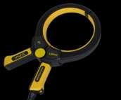
5 Accessories Provide Additional Functionality Sondes Non metallic pipe location Tracing CCTV sewer camera in cast iron or non-metallic pipe A-frame Cable sheath fault finding Pipe coating evaluation Remote Antenna & Signal Clamp Cable identification 5
 lead to power (NOT charge)")


 12ft")

")
6 Loc-10Tx-Power Lead (12V DC) 30ft (10m) lead to power (NOT charge) the transmitter from a vehicle LPC Separation Filter Apply the transmitter signal to the live domestic wiring system onto the service cable and the supply cable in the street Accessories Provide Additional Functionality vlocpro-charging Lead (12V DC) 12ft (4m)long lead to charge the receiver battery (or aux battery pack) while on the move vlocpro-aux Battery (12V DC-Ni-MH) Loc-10Tx-Battery Tray & Charger ( V AC 12V DC-Ni-MH) 6

7 Locators do NOT locate buried cables or pipes Locators DETECT electromagnetic SIGNALS radiating from metallic cables & pipes 7

8 The Locating Signal Is produced by the flow of the alternating current (AC) which creates an electromagnetic field. This electromagnetic field radiates from the line and is known as the signal. 8
9 The Locating Signal if there is NO AC CURRENT FLOWING, there will be NO LOCATING SIGNAL. 9
 and back to")

10 The Locating Signal Signals are created by the current flowing from the transmitter which travel along the conductor (line/cable/pipe) and back to the transmitter. The current typically uses the ground to complete the current. The ground stake is used to complete the circuit through the ground. 10

 means 8000 times per second.")
11 The Locating Signal We think of the signal traveling from the transmitter and back to the ground stake. In fact the signal is continually changing direction, flowing back and forth. The rate at which it changes is called frequency, so for instance, 50Hz means the signal changes direction 50 times per second, 8000Hz (or 8 khz) means 8000 times per second. (The k denotes 1000) The frequency is chosen depending on the application. 11

12 The Locating Signal Signals may use other pipes and cables to turn to the transmitter because they represent a lower resistance than the ground. 12


13 The Locating Signal Because of these return currents the ELECTROMAGNETIC FIELDS surrounding the line can be DISTORTED by return currents on other metallic lines. 13
. These sensors are known as antennas.")
14 Detecting The Locating Signal The locator receiver contains sensors that detect the electromagnetic field (the signal). These sensors are known as antennas. The signal induces a response in the antennas by electromagnetic induction. 14

15 The response to the signal There are several antennas in a locator, these can be used in different combinations. Each combinations (known as modes) provides a different types of response. The three main types of response for general locating are Peak, Null and Compass LR indication. Two additional modes are often used for specific applications Broad Peak (useful when locating very deep linesoperates like peak mode) Sonde Mode (for locating Sondes or CCTV inspection cameras see Sonde section) 15
16 Modes Peak mode provides a maximum response over the line 16

17 Modes Null mode provides a minimum response over the line 17


18 Compass LR Modes Provides direction & orientation to the line 18
19 Modes Broad Peak Provides increased sensitivity locating for deep pipes But response is broader, so more difficult to pinpoint 19

20 Sonde Modes A way to locate small self contained transmitter (used in non metallic pipes & some cast iron pipes 20
21 Signals used for locating can originate from a transmitter (active locating), or a variety of other sources (passive locating) 21
 Application specific signals from specific applications (CATV, Cathodic protection etc.")
22 Passive Signals Power power transmission & distribution networks (50/60Hz & related harmonics) Radio radio transmissions (15 khz 27 khz & related harmonics) Application specific signals from specific applications (CATV, Cathodic protection etc.) 22

23 Passive Signals Sources Power Signals From cables carry electric current. From pipes or cables carrying return electric current. Cables may be live but carry NO current. Pot-ended cables carry NO current. 23

24 Passive Signals Sources Radio Signals Mainly generated by high power, low frequency (LF) communication transmitter. Buried cables and pipes act as antennas that re-radiate the signal. Radio signals are best reradiated if the line is grounded at both ends. 24
, or to provide cathodic protection to pipes.")
25 Passive Signals Sources Application Specific Some cables & pipes radiate signals that are used as a carrier signal such as cable TV (CATV), or to provide cathodic protection to pipes. 25

26 Active Signals Active signals are applied by a locator transmitter Transmitter have one or more dedicated frequencies. The choice of frequency depends on the line being located, and the method the signal is applied. (Each manufacture offers slightly different frequencies) 26

27 Active Signals Three ways to apply the signal: Direct connection one cable to the target line, the other to ground. Clamp induces a signal into a cable, without making a direct connection. Induction induces a signal into a cable or pipe, by placing the transmitter on the surface over the target line. 27
28 Active Signal Frequency Low frequency (100Hz 1 khz) Cables Direct connection Long distance Low distortion Medium frequency (8 khz 33 khz) Cables & pipes Direct connection, clamp & induction Reasonable distance High frequency (65 khz 200 khz) Induction Short distance High distortion 28
29 Passive verses Active Location Passive Location Use to mark the location of unidentified buried lines before digging (Avoidance) Do NOT use to identify or trace specific lines Active Location Use to trace, identify & pinpoint a buried line Use to measure the depth of the buried line Use to measure the signal current on the buried line 29

30 Measuring Depth Depth & signal current can also be measured using a locator Depth is measured to the center of the signal in the case of a large pipe this is considerably different to the top of the pipe Some locators provide continuous depth this is only accurate when directly over the line 30
31 Measuring Depth The three (3) most common ways of measuring depth are: 1.Pushbutton Depth 2.Triangulation Depth 70% rule 3.Triangulation Depth 50% rule 31

32 Measuring Depth Pushbutton Depth All locators with pushbutton depth work in a similar way Position the locator over the cable using the Peak mode Press the depth button 32
33 Measuring Depth Triangulation Depth 70% rule Use Peak mode (two antennas). Locate cable, set gain to 100%. Without changing the gain setting move locator to one side until the gain reduces to 70% and mark the position. Return to the cable, ensure gain returns to 100%. Without changing the gain setting move locator to the other side until the gain reduces to 70% and mark the position. The depth is equal to the distance between the two points you marked. 33
34 Measuring Depth Triangulation Depth 50% rule Use Broad Peak mode.(single antenna) Locate cable, set gain to 100%. Without changing the gain setting move locator to one side until the gain reduces to 50% and mark the position. The depth is equal to the distance from the starting position to the 50% point you marked. Return to the cable, ensure gain returns to 100%. Without changing the gain setting move locator to the other side until the gain reduces to 50% and mark the position. This distance should be the same as the first measurement take. If it is not it is a clear indication of a distorted (or bent) field generally cause by signals radiating from adjacent cables. 34
35 Getting to Know the vlocpro The Principles of Cable & Pipe Location


36 The Receiver Model & Serial # Software Revision Number 36
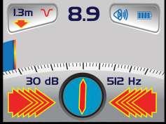
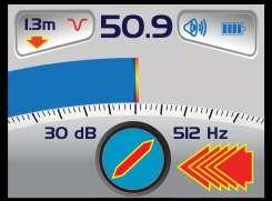
37 The Receiver Main Display. Location Mode Digital display of signal response Continuous Depth Analogue display of signal response Loudspeaker Status Battery Status Peak Signal Indication db sensitivity setting Compass (orientation to line) Frequency Left VS Right Indication 37
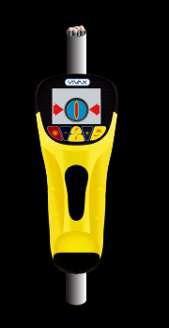
38 Receiver Controls Normal Use Frequency Select Gain Control (Increase gain) On / Off Control Location Mode Select Gain Control (Reduce gain) Information Depth / Current Measurement 38
39 Receiver Controls Setup Menu Up Down Select/De-select Enter / Exit Setup Menu (press briefly) 39

40 Receiver Setup Menu Speaker Volume - Off, Low, Medium, High Backlight - Off, Low, High Frequency - Enter - frequently used Language - English Imp/Metric - Meter, Feet Continuous Info - Depth, Current, Off Power Sound - Normal, Modulated Radio Sound - Normal, Modulated Active Sound - Normal, Modulated Locate Mode - Enter - Mode Selection - Peak, Null, Sonde, Broad, Peak Arrows Bluetooth Pairing - to pair with Bluetooth device Bluetooth Search - to search for Bluetooth device 40

41 Receiver Setup Menu Not selected Selected 41


 Data socket (for")
 Accessory")
 Battery")
42 Receiver External Connections External connections are as follows: Charging socket (for internal rechargeable battery) Data socket (for programming & data applications) Accessory socket (for receiver accessories) Battery connection lead (for connecting AA alkaline battery pack) 42
 Auxiliary pack (removable) Replace the AA removable pack with a rechargeable pack")

43 Receiver Batteries The locator has three battery pack: Rechargeable (internal) Main power source 6 x AA Alkaline (removable) Backup power Easily available (Optional) Auxiliary pack (removable) Replace the AA removable pack with a rechargeable pack (Optional) Vehicle charging lead for internal & external charging is available Inserting the AA backup pack will isolate the internal rechargeable pack. The auxiliary battery pack is charged externally. Dispose of batteries sensible, never dispose of in fire. 43


44 The Transmitter Model & Serial # labels Software Revision Number 44
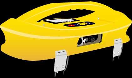
45 The Transmitter High voltage warning Frequency being transmitted Digital read out (mamps, volts, ohms) Loudspeaker Level Battery Status Units (mamps, volts, ohms) Low power indicator Output Setting (Step) Mode Indication 45
46 The Transmitter Output decrease On / Off Control Frequency select Information (Volume, Volts, Ohms) Output increase 46
 Fuse (250V replaceable) (to protect against incoming line voltage) Battery charging socket Loudspeaker When powering the transmitter from an external 12V DC source")
47 External connections The Transmitter Output connection High voltage protection (Fuse) Output socket (for direct connection leads & clamp) Power in socket (for main charger or powering transmitter from external 12V DC source) Fuse (250V replaceable) (to protect against incoming line voltage) Battery charging socket Loudspeaker When powering the transmitter from an external 12V DC source battery charging is disabled. The small hole on this panel is to enable the audio to be heard. All transmitters are fitted and wired to allow charging of a rechargeable battery tray. 47


48 The Transmitter Three ways to apply the signal: Direct connection one cable to the target line, the other to ground Clamp induces a signal into a cable, without making a direct connection Induction induces a signal into a cable or pipe, by placing the transmitter on the surface over the target line 48
49 The Transmitter Three transmitting modes: Direct Connection Mode selects automatically when plugging in the connection leads Signal Clamp Mode selects automatically when plugging in the clamp Induction Mode default mode when nothing is plugged in 49


50 The Transmitter To select frequency Press the f button to toggle between the available frequencies until the desired frequency is displayed. 50


51 The Transmitter The i pushbutton The default setting displays current Press once to display the speaker status, adjust using the - / + pushbutton Press again to display voltage (volts) 51

52 The Transmitter Press again to display electrical resistance (ohms) Press again to display second frequency menu, use the + and - keys to scroll through the available frequencies and bring the wanted one in the box. Press f key to select the second frequency and exit the submenu to return to the main display. Press again to display Frequency Menu, use + or - buttons to scroll through the available frequencies. Once the wanted frequency is inside the box, press f button to select or deselect the frequency. An x will appear in the box for a selected frequency. 52

53 Protection The Transmitter The transmitter checks the line when connected, if the line is carrying in excess of 35V, it will display High Voltage and not allow the transmitter to operate. In addition the transmitter is protected by a 1.25A / 250V fuse in the event of excessive voltage or voltage spikes on the line. 53
 The label differentiate the type of batteries")
54 The Transmitter Batteries Two battery trays available Alkaline 10 x D cells Rechargeable 12 x D cells (Ni-MH) The label differentiate the type of batteries installed 54
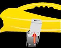
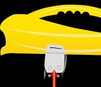


55 The Transmitter Removing the batteries trays 55
56 Using A Locator The Principles of Cable & Pipe Location

57 Using the Receiver Move the receiver forwards and backwards across the line in a smooth action Rotate the receiver to establish the direction of the line 57
58 Using the Receiver The Null mode will NOT indicate the direction of the line using the null signal strength alone. The left/right arrows and compass help to orient the locator to the line. 58
59 Using the Receiver The Compass LR mode will indicate the direction of the line, the left/right arrows & compass help you orient the locator to the line. Peak signal when over the line Null signal when at 90 0 to the line 59
 Compass LR mode Similar use as Null mode (swap to Peak mode to pinpoint)")
60 Using the Receiver Select the locating mode: Peak mode Best for tracing and pinpoint the line in congested areas Null mode Best for following a line if tracing for some distance (swap to Peak mode to pinpoint) Compass LR mode Similar use as Null mode (swap to Peak mode to pinpoint) 60
61 To locate a line an electric current must be flowing. 61


62 This electric current may originate from other sources (Passive Locating) or from the transmitter (Active Locating). 62
63 When to Use Passive Modes Always Call Before You Dig and follow your own company s work & safety practices. Always follows local, state, national, regulations and your own company safety and work practices. Search for unknown buried lines when applying a transmitter signal is not practical to verify the presence of adjacent lines A last check before digging For small localized digging (planting a fencepost or road sign) 63
64 When to Use Active Modes Always Call Before You Dig and follow your own company s work & safety practices. Always follows local, state, national, regulations and your own company safety and work practices. When locating a specific line in congested areas When tracing a specific line for any distance When pinpointing a buried line When a depth measurement is required 64
65 Passive Locating Passive locating is generally used to AVOID rather than identify buried lines. Using only the receiver, sweep the area in the search pattern shown. Sweep in Power mode, then Radio mode. 65
66 Applying The Transmitter Signal to The Line There are three (3) methods of applying an active signal to a line: 1. Direct connection (preferred) 2. Using a signal clamp 3. Induction 66
67 Direct Connection 67
68 Using A Signal Clamp 68
69 Induction Mode 69
70 Applying The Transmitter Signal to The Line Direct connection Direct connection is suitable when there is safe to the target line One connection lead (black clip) to ground (using the ground stake) One connection lead (red clip) to the line 70


71 Applying The Transmitter Signal to The Line Direct connection Plug the connection lead into transmitter Remove any rust or paint to ensure a good electrical connection Place the ground stake in the ground at 90 0 to the cable and as far away as practical Remember you want good electrical contact to make the current flow 71
72 Applying The Transmitter Signal to The Line Direct connection When positioning the ground stake to minimize coupling to other lines Do NOT place it close to other lines Do NOT place it the other side of adjacent lines Do NOT place it close to metallic fences or barriers 72

73 Direct connection Applying The Transmitter Signal to The Line Use the minimum output power needed to successfully locate the target line Excess power may increase the risk of coupling to other lines. This can make locating more difficult, and increases the risk of mis-locating. More power reduces battery life. The transmitter display will confirm how much current is being applied to the line indicating a good or bad connection. A change in speaker tone also confirms a good or bad connection. If the display shows no current or there is no change of speaker tone check the connection to the target line. 73


74 Using a Signal Clamp Applying The Transmitter Signal to The Line Use when you cannot connect to a conductor, or insulated sheath or for cable identification. Place the clamp around the line. Connect below the grounding point. (to ensure the signal has a signal path between near and far ground points) A transmitter ground connection is not required when using the clamp. (target line must be grounded at each end) Clamps are designed for specific frequencies only (typically 8 khz 83 khz) 74
 It may couple to other metallic lines & structures adjacent to target line")
75 Induction Applying The Transmitter Signal to The Line Allows signal to be applied to a line without access to the line The applied signal is generally less than the other connection methods (as the signal has to travel through ground to reach the line) It may couple to other metallic lines & structures adjacent to target line 75
76 Induction Applying The Transmitter Signal to The Line Place the transmitter over and in line with the target line at a known point (close to, but not on an access point such as a manhole, handhold or pedestal) Ensure the transmitter is oriented correctly 76
77 Induction Applying The Transmitter Signal to The Line Never locate within 15ft (5m) of the transmitter (the signal from the transmitter has an airborne element which you will locate) Never place on top of a manhole cover or metal plate (the signal will not penetrate to the line and may in fact damage the transmitter) The accuracy of depth readings may be influenced if taken close to a transmitter on induction 77
78 Induction Applying The Transmitter Signal to The Line One other technique that can be undertaken with induction is an ACTIVE sweep One person carries the transmitter in induction mode Another person 25ft (8m) away carries the receiver 78
 The distance from the transmitter The type of line being")
79 Applying The Transmitter Signal to The Line Frequency Most transmitters can transmit several different frequencies Different manufacturers use different frequencies The best frequency for the job will vary depending on the way the signal is applied (direct connection, signal clamp, induction) The distance from the transmitter The type of line being located 79

80 Frequency Applying The Transmitter Signal to The Line Low Frequency (100Hz 1 khz) Cables & insulated pipes & cable identification Direct connection Long distance Less coupling to adjacent lines 80
81 Frequency Applying The Transmitter Signal to The Line Medium Frequency (8 khz 33 khz) General purpose Cables & pipes Direct connection, clamp & induction Moderate distance 81
82 Frequency Applying The Transmitter Signal to The Line High Frequency (65 khz 200 khz) High resistance or poorly grounded Good for jumping insulated joints Most suited to induction Generally shorter distance Will couple to adjacent lines 82
83 Frequency Summary Low Frequency goes the farthest on cables, insulated pipe and cable identification using direct connection Medium Frequency good all round locating frequencies using any method of applying the signal High Frequency Applying The Transmitter Signal to The Line good for induction, short distance & badly grounded lines 83

84 Active Locating Active location is generally used to TRACE and PINPOINT a specific buried line. Active location always require a transmitter and receiver. TRACING is following the path of the buried line from, or to, the transmitter. 84

85 Active Locating To pinpoint and establish the position and direction of the line: Precisely locate the peak signal Rotate the receiver until the maximum signal 85

86 Measuring Depth & Current To take a depth & current measurement, first pinpoint the line Momentarily press & release the i button and depth & current will be displayed 86
87 Measuring Depth & Current Do NOT rely on depth & current measurements made if Close to bends in the line Close to Tee s in the line Close to the transmitter Where the line is changing depth Where the field distortion has been identified All of these factors can result in inaccurate depth & current readings. 87
88 Distorted Fields The magnetic field (the signal) radiating from buried lines can be distorted by the presence of adjacent metallic conductors or other signals. This is caused by: Signals induced from the target line to other lines Commonly bonded structures Badly positioned ground (at the transmitter) The result is that the locator detects signals from more than one course. 88


89 Distorted Fields A typical distorted field 89
90 Identifying A Distorted Fields Using Peak & Null modes to identify a distorted fields On a clean undistorted field the Peak and Null locate response will match If distortion is present, the peak and null locate response will no longer match. Typically, the greater the distortion, the further apart these locate responses will be. 90
91 Identifying A Distorted Fields Using Depth Measurement to identify a vertical distorted field Locate the line & measure depth with the locator resting on the ground Lift the receiver off the ground by a known distance (say) 1ft (30cm) Take another depth reading The depth reading should have increase by the distance you raised the receiver if significantly different the field is distorted. 91

92 Using Signal Current to Help Identify The Target Line Current readings are not influenced by depth. Current readings should not be higher than the current being transmitted. 92
93 Using Signal Current to Help Identify The Target Line Current readings will reduce gradually unless There is a Tee in the line A large fault in the insulation Or you are locating the wrong line 93
94 Passive Electronic Marker System (EMS)
95 EMS EMS markers are used to mark below ground points of interest such as splice joints or buried valves or to mark the position and route of non metallic services such as plastic pipes. 95

96 EMS Theory An EMS marker consists of a coil of wire which is connected in parallel with a resonating capacitor. 96

97 EMS Theory The coil and capacitor are chosen so that they have a particular resonant frequency. When the circuit is hit with a pulse of electromagnetic energy the circuit resonates causing currents to flow in the circuit. 97


98 EMS Theory To imagine the resonance consider the audio equivalent. Imagine a glass being tapped. The glass will resonate at the natural frequency of the glass in a similar way the EMS marker electronically resonates at its resonant frequency. 98


99 EMS Theory Currents flowing in the EMS marker create a return signal. 99

100 EMS Theory The original pulse is created by an above ground device. It consists of an electronic circuit that energises a transmitting coil. 100
101 Vivax vlocml The vlocml can detect markers in two modes of operation: 1. Dedicated The locator is dedicated to locating a predefined marker type. 2. Dual The locator is used to locate a cable or conductive pipe whilst simultaneously search for a particular marker type. 101

102 vlocml Dedicated Screen Dual Screen 102

103 Types of EMS Marker Markers vary in size and shape but typical ones are : 1. Near surface marker range 600mm 2. Ball marker range 1.5m 3. Full range marker range 2.4m 103

104 Types of Marker Different frequency markers are used to distinguish different utilities and are differentiated by colour. 104
105 Signal Direction

106 Signal Direction Identification Connect the transmitter to the target line using a direct connection only. If several lines are commonly bonded the Signal Direction will carry through to the other lines. This is useful for locating multiple line installations. When performing a reset, take care to ensure that you have not strayed from the target line. There will be a point at which it is not possible to reset and continue. However beware that if a non target line is commonly bonded to the target line that line will also appear as being in Sync with the target line. 106
107 Signal Direction Identification Turn the transmitter and receiver on and set both to : SD-USA if in North America or any territory where the power system is 60Hz. SD-EUR if in Europe or any territory where the power system is 50Hz. The receiver may, or may not be flashing the SD icon and compass bezel. 107

108 Signal Direction Identification To synchronize the receiver to the transmitter at the beginning of a survey, pinpoint the line very close to the transmitter. Stand facing away from where the transmitter is attached and press i pushbutton. Press the return pushbutton will synchronize the system, then return the unit to the locate screen. The top portion of the bezel surrounding the compass will light and not be flashing indicating the receiver is locked onto the signal. 108

109 Signal Direction Identification Proceed to locate, trace, pinpoint as required ensuring at all times the top portion of the compass bezel remains illuminated. If at any time top portion of the bezel ceases to be illuminated and the bottom portion of the compass bezel lights up you are locating the wrong line which is carrying the return signal. 109

110 Signal Direction Identification The top or bottom portion of the compass bezel together with the SD icon and start flashing this indicating that synchronization with the transmitter has deteriorated and a reset is required. 110

111 Signal Direction Identification Re-trace your line back to a point where a solid signal direction is obtained. Precisely pinpoint the line and stand with your back to the direction of the transmitter Press the i pushbutton Press the enter pushbutton to re-sync with the transmitter signal. Continue to locate, pinpoint and trace. 111


 CSV")
 Google")
112 Bluetooth GPS vlocpro Receivers Optional Bluetooth Connectivity Connects to most GPS receivers ESRI SHP files (SHP, DBF, SHX) CSV generic text file format (CSV) Google Earth KML file format (KML) 112

113 GPS Accuracy 113

114 Bluetooth GPS 114


115 vlocml vlocml SebaKMT, 3M (EMS) & Omni Marker s 115
116 Accessories The Principles of Cable & Pipe Location
117 Accessories A-frame Typical uses Finding faults to ground on cables Evaluating the condition of pipe coating 117

118 Accessories A-frame Cable and Pipeline Faultfinding The accessory A-frame can be used to detect the position of cable and pipeline defects where they are in contact with the ground. 118
119 Accessories A-frame Disconnect any ground connections other than the transmitter ground, to encourage the signal to return through the fault Use FF mode on transmitter and receiver 119


120 Accessories A-frame Cable and Pipeline Faultfinding For best results the target line should be isolated and all ground bonds removed. Failure to isolate the line will allow the signal current to enter the ground at these points and will results in misleading results. 120
121 Accessories A-frame Cable and Pipeline Faultfinding As the fault is neared, the arrow on the locator display will point forward and the db reading increase. As the fault is passed the arrow will flip to point in reverse. When the spikes of the A-frame are exactly straddled the fault, the db reading will drop dramatically and the arrows will either, both be on, or will flip forwards and backwards. 121

122 Accessories A-frame Cable and Pipeline Faultfinding Repeat the process at 90 o to the position of the fault to identify the position laterally. Where the two lines cross is the position of the fault. 122


123 Accessories A-frame Cable and Pipeline Faultfinding If it is suspected that there is just one fault on the line, the A-frame can be used to estimate the magnitude of the fault. Position the A-frame approximately one meter from the earth stake. Note the db reading which will be similar to the maximum db reading at the fault. 123
 to apply the transmitter signal The")

124 Accessories Live Plug Connector Apply the Live Plug Connector to a normal household power socket (100V 250V AC) to apply the transmitter signal The transmitter is protected by an isolating transformer built into the accessory Use with the receiver or the remote antenna to detect the signal as it leaves the premises 124


125 Accessories Remote Antenna & Signal Clamp Used to identify cables 125
126 Accessories Remote Antenna & Signal Clamp Signal Clamp Set transmitter & receiver to 8 khz / 33 khz / 65 khz Select the Peak mode on the receiver Remote Antenna Place the remote antenna onto the cable Locate the cable with the strangest source of your signal 126
127 Accessories Sondes A Sonde is a small self contained transmitter. Sondes are inserted into non metallic pipes or ducts to make them locatable or to find blockages. Higher frequency (33 khz) are used for non-metallic pipes. Some low frequency Sondes (512Hz/640Hz) will transmit through cast iron pipe. 127

128 Accessories Sondes Sondes radiate a signal with a different shape to the signals radiated from cables 128

 Take the receiver and select both the")
129 Accessories Sondes Because the signal radiates differently, we orientate the receiver differently & use a specific Sonde mode. (on the receiver) Take the receiver and select both the Sonde mode and the correct Sonde frequency. 129

130 Accessories Sondes The Sonde signal gives three peaks in line with the path of the Sonde. And a single peak across the line of the Sonde. 130

131 Accessories Sondes The compass can be used to efficiently locate the position of a Sonde. Position the locator in the approximate area of the Sonde. Rotate the locator so that the compass is pointing at 12 o clock. Walk forward keeping the compass at 12 o clock. Adjust the gain as the signal strength increases. The position of the Sonde is indicated by the maximum signal strength. 131
 They are often incorporated in other equipment.")
 Depth to the Sonde can be")
132 Accessories Sondes Sondes are fitted or taped to pushrods. (snakes) They are often incorporated in other equipment. Typical examples are: CCTV (Sewer) Inspection Cameras Jetters Horizontal boring devices (These Sondes may be powered by batteries or by other devices) Depth to the Sonde can be measure by pressing the depth button, however you MUST be in SONDE MODE. 132

133 Battery Care & Maintenance The following will help you extend the life of your rechargeable batteries Only use the correct charger provided by Vivax When you first get the units charge them for a minimum of 8 hours, during that period do not switch off or disconnect If at any time the battery life per charge reduces run the rechargeable until they are completely dead, then charge for 8 hours, use the unit for 15 mins and then charge for another 8 hours. A heat sensing switch is included in both the transmitter and receiver rechargeable battery packs to immediately stop the charging cycle if the temperature of the batteries rises to unacceptable levels. Additional battery packs that can be placed in the Alkaline compartment of the receiver are also available. These must be taken out of the unit for charging. Vehicle cigarette type charging leads are also available for the Receiver internal rechargeable battery and the accessory rechargeable pack. 133
134 Safety Locators are precision well engineered tools, however the environment we locate in is not perfect. Always be aware of the influence of distorted fields Always take account of visual clues (manholes, pedestals etc) Always use as built plans if available NEVER use digging machinery over marked out pipes or cables Do NOT give depth information unless authorized by your company Follow all Federal, State, and company rules and regulations particularly as regards safety Dispose of Batteries in line with Federal, State or company regulations Never submit batteries to extreme heat or fire. CALL BEFORE YOU DIG - ALWAYS DIG CAREFULLY 134
135 Glossary Active Locate Active Signal Attenuation Clamp (or Coupler) Coupling A locate where a transmitter is used to apply a signal to a buried pipe or cable, the position of which is then located by a receiver tuned to the same frequency. A signal applied by the locator transmitter to a buried line. Typical this is a very precise frequency. The reduction of an electromagnetic signal from a pipe or cable. An accessory used to apply the transmitter signal to an insulated line, removing the need to connect the transmitter signal directly to a conductor or cable sheath. The act of signals transferring to lines to which they were not originally applied. Coupling can be direct where the target line has an electrical connection to another line, or induced where the signal radiates from the target line to another line or lines. 135
136 Glossary Display Line Null Passive Locate Passive Signals Peak Compass The information visually available on the dot matrix display. A generic term for any buried pipe or cable. A minimum response to a buried line. A locate where the receiver searches for a wide range of signals that radiate from buried pipes or cables. These signals come from a variety of sources in the environment and couple to the buried (& overhead) lines. Typical examples 50/60Hz and LF/VLF radio. A wide range of signals that radiate from buried pipes or cables. These signals come from a variety of sources in the environment and couple to the buried (& overhead) lines. Typical examples 50/60Hz and LF/VLF radio. A maximum response to a buried line. Line direction indicator. (Although visually like a compass, this is the only relation to a compass.) 136
137 Glossary Pinpoint Target Line Trace Response Search (sweep) Sonde Using a receiver to identify the exact position of a buried line. The buries pipe or cable to be located. Using a locator to following the path of a buries line. The indication that the receiver gives which is caused by the signals it is receiving. This can be visual, audio or both. Typically it is displayed on the locators dot matrix display and audibly from a loudspeaker in the receiver housing. This describes the act of looking for a buried line within a given area. A small transmitting coil which may be built into a product such as a sewer camera or packaged as a small self contained battery powered transmitter. A receiver tuned to the same frequency can locate the position of the Sonde and hence whatever it is attached to or in. Frequently used for locating sewer cameras and the non metallic pipes. 137
138 Vivax-Metrotech Contact Details Vivax-Metrotech works throughout the world with skilled professionals experienced in cable and pipe location United State of America Vivax-Metrotech Corporation 3251 Olcott Street, Santa Clara, CA 95054, USA Website : Canada Vivax Canada Inc. 400 Esna Park Drive, Unit 17, Markham, Ontario, L3R 3K2, Canada Sales & Sales Support: T/Free : Tel : Fax : sales@vxmt.com Application Support: T/Free : Tel : Fax : applications@vxmt.com Service & Repairs: T/Free : Tel : Fax : service@vxmt.com All Other Department: T/Free : Tel : Fax : Tel : Website : www. vivax-metrotech.com CanadianSales@vxmt.com 138
139 Vivax-Metrotech Contact Details Europe SebaKMT Seba Dynatronic Mess-und Ortungstechnik GmbH Dr.-Herbert-Iann-Str. 6, Baunach, Germany Tel : Fax : Website : service@sebakmt.com Australasia SebaKMT AUS Unit 1, 176 South Creek Road, Cromer NSW 2009, Australia Tel : Fax : Website : sales@sebakmtaus.com service@sebakmtaus.com China Leidi Utility Supply (Shanghai) Ltd. Rm405 3rd Building No. 641, Tianshan Rd, Shanghai, China Tel : Fax : Website : info@leidi.cn 139
140 The End The Principles of Cable & Pipe Location 140
Loc-5Tx Data Sheet V2.1
 A. Typical Applications Description Uses Pipe & cable locator transmitter Transmitting active signals for the location of buried pipes and cables B. Transmitter Assembly Construction Weight Dimension Display
vloc Series 2 Smaller and lighter Over four times battery life Define, set and lock available features Customizable startup screen and much more...
 vloc Series 2 Smaller and lighter Over four times battery life Define, set and lock available features Customizable startup screen and much more... Locate with Accuracy and Confidence Precision instruments
vloc-9800 User Handbook
 vloc-9800 User Handbook (English Edition) Version 1.1 Table of Content General Safety & Care Information... 1 1.1 Who Can Use This Equipment... 1 1.2 Work-site Safety... 1 1.3 Equipment Safety... 1 1.4
vloc-9800 User Handbook (English Edition) Version 1.2
 Version 1.2") vloc-9800 User Handbook (English Edition) Version 1.2 Table of Content General Safety & Care Information...1 1.1 Who Can Use This Equipment...1 1.2 Work-site Safety...1 1.3 Equipment Safety...1 1.4 Batteries
vloc-9800 User Handbook (English Edition) Version 1.2 Table of Content General Safety & Care Information...1 1.1 Who Can Use This Equipment...1 1.2 Work-site Safety...1 1.3 Equipment Safety...1 1.4 Batteries
vloc Series 2 User Handbook (vlocpro2, vlocml2)
") vloc Series 2 User Handbook (vlocpro2, vlocml2) (English Edition) Version 1.2 Table of Content General Safety & Care Information... 1 1.1 Who Can Use This Equipment... 1 1.2 Work-site Safety... 1 1.3 Equipment
vloc Series 2 User Handbook (vlocpro2, vlocml2) (English Edition) Version 1.2 Table of Content General Safety & Care Information... 1 1.1 Who Can Use This Equipment... 1 1.2 Work-site Safety... 1 1.3 Equipment
QLD/NT NSW WA
 vlocpro2 vlocpro2 features enhance productive location Rugged ABS & carbon fiber construction IP54 rating for all weather use Color display High speed dual core processor Multiple location modes with compass
9800 XT. Utility Line Locator OPERATIONS MANUAL SERVICE CENTER, SALES AND TECHNICAL SUPPORT INFORMATION. Page 1 of 45
 9800 XT OPERATIONS MANUAL Utility Line Locator SERVICE CENTER, SALES AND TECHNICAL SUPPORT INFORMATION Vivax-Metrotech Corporation 3251 Olcott Street, Santa Clara, CA 95054, USA Website : www.vivax-metrotech.com
vlocdm2 User Handbook
 vlocdm2 User Handbook (English Edition) Version 1.1 Table of Content General Safety & Care Information... 1 1.1 Who Can Use This Equipment... 1 1.2 Work-site Safety... 1 1.3 Equipment Safety... 1 1.4 Batteries
Dynatel 2250E/2273E Advanced Cable and Fault Locator
 Dynatel 2250E/2273E Advanced Cable and Fault Locator Operators Manual September 1999 78-8097-6500-7-B TABLE OF CONTENTS Introduction... 2 Installing or Replacing the Batteries... 2 Initial Receiver Configuration...
vscan Data Sheet V1.0
 A. The vscan System The vscan receiver, and (optional) transmitter, are used for locating buried utilities. The vscanm incorporates all the vscan features plus a metal cover locating mode. The system is
vlocdm User Handbook (English Edition) Version 2.0
 Version 2.0") vlocdm User Handbook (English Edition) Version 2.0 Table of Content 1. General Safety & Care Information 1.1 Who Can Use this Equipment 1.2 Work-site Safety 1.3 Equipment Safety 1.4 Batteries and Environmental
vlocdm User Handbook (English Edition) Version 2.0 Table of Content 1. General Safety & Care Information 1.1 Who Can Use this Equipment 1.2 Work-site Safety 1.3 Equipment Safety 1.4 Batteries and Environmental
vloc Series 2 User Handbook (vlocpro2, vlocml2) (English Edition) Version 1.5
 (English Edition) Version 1.5") vloc Series 2 User Handbook (vlocpro2, vlocml2) (English Edition) Version 1.5 Table of Content General Safety & Care Information 1 1.1 Who Can Use This Equipment 1 1.2 Work-site Safety 1 1.3 Equipment
vloc Series 2 User Handbook (vlocpro2, vlocml2) (English Edition) Version 1.5 Table of Content General Safety & Care Information 1 1.1 Who Can Use This Equipment 1 1.2 Work-site Safety 1 1.3 Equipment
vloc-9800 User Handbook (English Edition) Version 1.3 P/N:
 Version 1.3 P/N:") vloc-9800 User Handbook (English Edition) Version 1.3 P/N: 4.04.000022 Table of Content General Safety & Care Information...1 1.1 Who Can Use This Equipment...1 1.2 Work-site Safety...1 1.3 Equipment
vloc-9800 User Handbook (English Edition) Version 1.3 P/N: 4.04.000022 Table of Content General Safety & Care Information...1 1.1 Who Can Use This Equipment...1 1.2 Work-site Safety...1 1.3 Equipment
VM-480B User Handbook (English Edition) Version 1.3 P/N:
 Version 1.3 P/N:") VM-480B User Handbook (English Edition) Version 1.3 P/N:4.04.000029 Table of Content General Safety & Care Information 1 1.1 Who Can Use This Equipment 1 1.2 Work-site Safety 1 1.3 Equipment Safety 1
VM-480B User Handbook (English Edition) Version 1.3 P/N:4.04.000029 Table of Content General Safety & Care Information 1 1.1 Who Can Use This Equipment 1 1.2 Work-site Safety 1 1.3 Equipment Safety 1
vlocpro NEW Features & Accessories NEW Standard Features available now! New Displays
 vlocpro NEW Features & Accessories NEW Standard Features available now! New color display format Compass mode Continuous depth measurement (slectable) Progressive left/right indication Enhanced passive
UTILITY LOCATING EQUIPMENT
 RIDGID SEEKTECH LOCATING RECEIVERS RIDGID locating receivers feature an easy-to-use visual mapping display that allows you to locate utility lines and sondes/beacons with confidence. Use with a SeeSnake
vloc3-pro User Handbook (English Edition) Version 1.2 P/N:
 Version 1.2 P/N:") vloc3-pro User Handbook (English Edition) Version 1.2 P/N: 4.04.000105 Table of Content 1. General Safety & Care Information...1 1.1 Who Can Use This Equipment...1 1.2 Work-site Safety...1 1.3 Equipment
vloc3-pro User Handbook (English Edition) Version 1.2 P/N: 4.04.000105 Table of Content 1. General Safety & Care Information...1 1.1 Who Can Use This Equipment...1 1.2 Work-site Safety...1 1.3 Equipment
vscan User Handbook (English Edition) Version 1.0 P/N:
 Version 1.0 P/N:") vscan User Handbook (English Edition) Version 1.0 P/N: 4.04.000051 Table of Content Introduction...1 1.1 General Safety & Care Information...1 1.1.1 Work-site Safety...1 1.1.2 Equipment Safety...1 1.1.3
vscan User Handbook (English Edition) Version 1.0 P/N: 4.04.000051 Table of Content Introduction...1 1.1 General Safety & Care Information...1 1.1.1 Work-site Safety...1 1.1.2 Equipment Safety...1 1.1.3
vscan User Handbook (English Edition) Version 1.0 P/N:
 Version 1.0 P/N:") vscan User Handbook (English Edition) Version 1.0 P/N: 4.04.000051 Table of Content Introduction... 1 1.1 General Safety & Care Information... 1 1.1.1 Work-site Safety... 1 1.1.2 Equipment Safety... 1
vscan User Handbook (English Edition) Version 1.0 P/N: 4.04.000051 Table of Content Introduction... 1 1.1 General Safety & Care Information... 1 1.1.1 Work-site Safety... 1 1.1.2 Equipment Safety... 1
Radiodetection. Fundamental principles and techniques in buried utility location
 Fundamental principles and techniques in buried utility location Canada 344 Edgeley Blvd. Unit 34 Concord, Ontario L4K 4B7 1-800-665-7953 Pipe and Cable Locators don't find pipes and cables...? 2 ...they
UAT-600 Series. amprobe.com
 UAT-600 Series Underground Utilities Locator Accurately and safely pinpoint underground utilities before you dig Accidentally hitting a utility line during a project can lead to costly repairs and create
C.A.T and Genny User Guide. Revision
 C.A.T and Genny User Guide Revision 3-06.00 Troubleshooting When reporting any problem to your Radiodetection Dealer/Supplier it is important to quote the Receiver Serial Number. Warning: Radiodetection
vlocdm2 User Handbook
 vlocdm2 User Handbook (English Edition) Your Texas Vivax-Metrotech Dealer: Indepth Utility Solutions LLC Phone: 281-969-8530 www.indepthus.com email: info@indepthus.com Version 1.4 P/N: 4.04.000023 Table
Telephone Cable Locating Techniques
 Chapter 2 Telephone Cable Locating Techniques Introduction Read Chapter One of this manual to learn more general information about each of the following signal application methods. The following paragraphs
4.3.3 Induction (33 khz) Detecting Active Signals Taking Depth and Current Measurements Depth in power mode
 Detecting Active Signals Taking Depth and Current Measurements Depth in power mode") Table of Content Introduction...1 1.1 General Safety & Care Information...1 1.1.1 Work-site Safety...1 1.1.2 Equipment Safety...1 1.1.3 Batteries and Environmental Safety...1 1.1.3.1 Alkaline Batteries
Table of Content Introduction...1 1.1 General Safety & Care Information...1 1.1.1 Work-site Safety...1 1.1.2 Equipment Safety...1 1.1.3 Batteries and Environmental Safety...1 1.1.3.1 Alkaline Batteries
Nine LEDs provide feedback of transmitter operation. Induction selected One Red LED Frequency/Mode selection Four Green LEDs
 RD4000T and TF Transmitters Technical Specification Draft 0/07/0 Description: RD4000 transmitter Part No: 10/T * (*=version) 10/TF * (*=version) Physical: Construction High Impact thermoplastic injection
PIPELINE DEFECT MAPPER
 PIPELINE DEFECT MAPPER Receiver Colour Display C.A.T. Survey Graph ACVG Survey Graph GIS View General: The Pipeline Defect Mapper Kit designed and developed in such a way; to precisely locate and assist
Advanced Test Equipment Rentals ATEC (2832)
") Established 1981 Advanced Test Equipment Rentals www.atecorp.com 800-404-ATEC (2832) RADIODETECTION APPLICATIONS MANUAL Revision 0-06.97 CONTENTS 1 INTRODUCTION 2 HOW TO USE A RECEIVER 2.1 PASSIVE AND
Established 1981 Advanced Test Equipment Rentals www.atecorp.com 800-404-ATEC (2832) RADIODETECTION APPLICATIONS MANUAL Revision 0-06.97 CONTENTS 1 INTRODUCTION 2 HOW TO USE A RECEIVER 2.1 PASSIVE AND
Leica Digisystem Safe and fast location of underground services
 Leica Digisystem Safe and fast location of underground services Leica Digisystem Making Cable Avoidance Easier and Safer Every year site workers are injured due to inadvertently striking buried utilities
Instruction Manual CXL Locator DXL Locator MXL Locator SGA Signal Generator SGV Signal Generator MXT Transmitter
 Cable Avoidance Tool AS Cable Avoidance Tool Depth Measuring Cable Avoidance Tool AS Depth Measuring Cable Avoidance Tool AS Precision Pipe & Cable Locator Precision Pipe & Cable Locator PRECISION PIPE
Electronic Pipeline Technology
 Pipe and Cable Locator Pearson Holiday Detector Model EPT- 1000 Electronic Pipeline Technology Electronic Pipeline Technology 26 Palomino Drive, Richmond Hill, Ontario, Canada, L4C 0P8 Tel: (905) 918-0025
Pipe & cable locator for avoidance & tracing applications. The ideal choice for the novice through to the skilled technician
 vscan & vscanm Pipe & cable locator for avoidance & tracing applications vscan features and options Compass (line direction indicator) Self-test and calibration verification Data logging and data management
RD7000 Radiodetection s general utility cable and pipe locator.
 RD7000 Radiodetection s general utility cable and pipe locator. Operation Manual l Issue 1 l July 2008 90/RD7K-OPMAN-ENG/01 Preface Before you begin Thank you for your interest in Radiodetection s RD7000
VM-810/VM-850 Pipe and Cable Locator User Handbook
 VM-810/VM-850 Pipe and Cable Locator User Handbook (English Edition) Version 1.7 P/N: 4.04.000027 Table of Content General Safety & Care Information...1 1.1 Who Can Use This Equipment...1 1.2 Work-site
EDENBROS, LLC. RD Radiodetection s utility specific cable and pipe locators. Operation Manual l Issue 1 l January 2011
 EDENBROS, LLC RD7000 + Radiodetection s utility specific cable and pipe locators Operation Manual l Issue 1 l January 2011 90/RD7K+-OPMAN-ENG/01 EDENBROS, LLC PO BOX 247 ST. JAMES, MO 65559 Phone: +1 800-526-5246
General Warnings Non-Metallic Pipe Tracing Features Depth Measurement Locator Operating Modes Signal Current Measurement Function Checks
 CXL4 Cable Avoidance Tool DXL4 Depth Measuring Cable Avoidance Tool SGA4 Signal Generator SGV4 Signal Generator MXL4 Precision Pipe & Cable Locator MXT4 Transmitter INSTRUCTION MANUAL Contents General
Loc-1Tx/Loc-5Tx/Loc-10Tx Data Sheet V3.2
 Typical Applications Typical Applications Pipe & cable locator transmitter Transmitting active signals for the location of buried pipes and cables Construction High impact ABS Transmitter Assembly Weight
Dynatel. 2273M Cable/Pipe and Fault Locators 2273M-iD Cable/Pipe/Fault and Marker Locators with id Read/Write
 3 Dynatel 2273M Cable/Pipe and Fault Locators 2273M-iD Cable/Pipe/Fault and Marker Locators with id Read/Write Designed to be more accurate, faster and more integrated than any other locator on the market,
INDEX PREFACE... 1 CAUTIONS... 2 OPERATION ON SITE(9) STANDARD INSTRUMENT... 3 OPTIONAL ACCESSORIES... 4 OPERATION OF TRANSMITTER(3)...
 STANDARD INSTRUMENT... 3 OPTIONAL ACCESSORIES... 4 OPERATION OF TRANSMITTER(3)...") INDEX PREFACE... 1 CAUTIONS... 2 STANDARD INSTRUMENT... 3 OPTIONAL ACCESSORIES... 4 OPERATION OF TRANSMITTER(1)... 5 (Transmitter Unit.) OPERATION OF TRANSMITTER(2)... 6 (Operation Panel, LCD Display of
INDEX PREFACE... 1 CAUTIONS... 2 STANDARD INSTRUMENT... 3 OPTIONAL ACCESSORIES... 4 OPERATION OF TRANSMITTER(1)... 5 (Transmitter Unit.) OPERATION OF TRANSMITTER(2)... 6 (Operation Panel, LCD Display of
pipeline integrity PCM + Pipeline Current Mapper
 pipeline integrity PCM + Pipeline Current Mapper Fast locate and effective measurement of pipeline coating defects. The location and measurement of pipeline corrosion using electromagnetic detection devices
Locator Accessories DATA SHEETS. Accessory Range for Pipe & Cable Location Equipment
 Locator Accessories DATA SHEETS Accessory Range for Pipe & Cable Location Equipment GENERAL PURPOSE SONDE The C.SCOPE 8kHz and 33kHz General Purpose Sondes are transmitters used to trace the direction
AT-5000 Professional Underground Cable / Pipe Locator System
 AT-5000 Professional Underground Cable / Pipe Locator System Buried Utilities represent a major challenge to electricians who need to trace and trouble shoot such systems. They also represent a hazard
A higher performance product designed for safer excavating.
 The new MXL2 and MXT2 from C.Scope have been designed to set a new benchmark in excavating safety as well as still delivering all the advantages and familiar operating practices associated with the original
Leica Digicat i-series Safe and fast location of underground services
 Leica Digicat i-series Safe and fast location of underground services Leica Digicat i-series Making Cable Avoidance Easier and Safer Every year site workers are injured due to inadvertently striking buried
RD4000 Locating system
 RD4000 Locating system User Manual l Issue 4 l August 2008 90/UG060EN/04 Table of Contents FCC, CANADIAN, AND EUROPEAN SAFETY NOTICES... 6 RECEIVER... 6 USA... 6 Canada... 6 Europe... 6 TRANSMITTER (RD4000T3,
STAFF User Manual. Manual Part #
 STAFF User Manual Manual Part # 030-00085-00 Introduction Congratulations on the purchase of your new STAFF Secondary Fault Locator. The STAFF is specially designed to detect conductor to earth/ground
3M Dynatel Cable/Pipe/Fault Locator 2550/2573 Series
 3M Dynatel Cable/Pipe/Fault Locator 2550/2573 Series Operator s Manual 2550 Pipe/Cable Locator 2550-iD Pipe/Cable and Marker Locator 2573 Cable/Pipe/Fault Locator 2573-iD Cable/Pipe/Fault and Marker Locator
DynatelTM Cable Locator. Operators Manual. October Revision A
 DynatelTM 2210 Cable Locator Operators Manual October 1996 78 8097 5171 8 Revision A 3M TM Dynatel TM 2210 Cable Locator Operators Manual The information in this manual is proprietary to 3M and may not
Version 1.0 English. EziSYSTEM User Manual
 Version 1.0 English EziSYSTEM User Manual Introduction Introduction Purchase EziSYSTEM Congratulations on your purchase of an EziSYSTEM instrument. 2 This manual contains important safety directions as
INDEX. Accessories and Components System Unit and Joystick Assembly and Charging the Battery Using with LED System...
 USER GUIDE INDEX Accessories and Components... 4 System Unit and Joystick... 6 Assembly and Charging the Battery... 9 Using with LED System... 11 What is Ground Setting and How It Is Done... 14 Ground
User Manual Pathfinder Precision Locating System
 User Manual Pathfinder Precision Locating System Manual Part # 030-00113-00 Copyright Copyright 2017 RYCOM Instruments, Inc. All rights reserved. No part of this manual may be reproduced, copied, modified
User Manual 8880 Series Fault Finding & Locating Kit
 User Manual 8880 Series Fault Finding & Locating Kit Model 8880PLS STAFF Model 8880PLS HVDFF Manual Part # 030-00085-00 Rev E Table of Contents General Information Introduction...............................................
8873 v3 Pathfinder Locator User Manual
 8873 v3 Pathfinder Locator User Manual Manual Part # 030-00100-00 Rev B Table of Contents General Information Introduction...2 Prepare for Use....2 Receiver Operation.......................................
I N N O V A T I N G U N D E R G R O U N D L O C A T I N G
 Model CI-5120 CI-5120 RECEIVER SPECIFICATIONS RECEIVER Gun-Type Housing Three Position Swivel Antenna Signal Adjust Control Audio/Mute Switch Lighted Tracking Display Hi-Impact Plastic Carrying Case (Optional)
TW-82P DIGITAL LINE TRACER WITH PASSIVE POWER DETECTION. Operating Manual
 TW-82P DIGITAL LINE TRACER WITH PASSIVE POWER DETECTION Operating Manual Test Equipment Depot - 800.517.8431-99 Washington Street Melrose, MA 02176 TestEquipmentDepot.com CONTENTS Introduction... 3 Contents...4
cable and pipe locators RD Utility cable and pipe locator
 cable and pipe locators RD7000 + Utility cable and pipe locator RD7000 + delivering fast, accurate, reliable and repeatable locate information for all utilities. Visually follow the target cable or pipe
RD8100 OPTIMUM PRECISION FOR DAMAGE PREVENTION
 PRECISION locators RD8100 OPTIMUM PRECISION FOR DAMAGE PREVENTION Since Radiodetection launched the first commercial, twin antenna, cable and pipe locators over 40 years ago, we have pioneered many technologies
The new CXL2 and DXL2 Cable Avoidance Tools and SGA2 and SGV2 Signal Generators from C.Scope have been designed to set a new benchmark in excavating
 CXL2 DXL2 SGA2 SGV2 The new CXL2 and DXL2 Cable Avoidance Tools and SGA2 and SGV2 Signal Generators from C.Scope have been designed to set a new benchmark in excavating safety as well as still delivering
AT Underground Cable/Pipe Locator System. Users Manual Mode d emploi Bedienungshandbuch Manuale d Uso Manual de uso Användarhandbok
 AT-3500 Underground Cable/Pipe Locator System Users Manual Mode d emploi Bedienungshandbuch Manuale d Uso Manual de uso Användarhandbok For detailed specifications and ordering info go to www.testequipmentdepot.com
PRECISION PIPE AND CABLE LOCATION. Instruction Manual Function Checker
 PRECISION PIPE AND CABLE LOCATION Instruction Manual WARNINGS / NOTES WARNING The does not recalibrate, service or repair any C.Scope Cable Avoidance Tool, Locator, Signal Generator or Transmitter. The
Loki Pipe & Cable Locators
 Loki Pipe & Cable Locators User guide 90/UG114INT CONTRACTOR MODEL UTILITIES MODEL IMPORTANT SAFETY NOTICE Risk of property damage, death, or serious injury may result if buried pipes and cables are not
Tender NO. PGVCL/PROC/Cable & Pipeline Locator/832
 SPECIFICATION FOR Multipurpose Precision Locator for Cables and Pipes below Ground 1. SCOPE The Specification covers design, manufacturing Factory testing and supply of Multipurpose and Multi-function
Cable Identifier Reliable cable selection for energised and de-energised cables
 Reliable cable selection for energised and de-energised cables Inexpensive cable selection system Easy to operate Safe to handle Very small DESCRIPTION Clear identification of a cable before it is cut
Armada Technologies Pro900 Advanced Underground Locator USER GUIDE
 Pro900 Advanced Underground Locator USER GUIDE WARNING Read and understand the instructions before operating this unit. Failure to do so could lead to injury or death. The Armada Technologies Pro900 Advanced
Leica Digisystem i-series Safe and fast location of underground utilities
 Leica Digisystem i-series Safe and fast location of underground utilities Leica Digisystem i-series Making cable avoidance easier and safer Every year site workers are injured due to inadvertently striking
Cable I.D. Live. Primary or Secondary In or Out of the Trench TX-Former to TX-Former TX-Former to Meter Energized or Grounded.
 Cable I.D. Live Primary or Secondary In or Out of the Trench TX-Former to TX-Former TX-Former to Meter Energized or Grounded www.aquatronics.com i ii TABLE OF CONTENTS Warning Description Battery Test
Metrolog HL7000 TM. Acoustic Leak Logging System. Simple Reliable Efficient. Reduce Water Leaks Faster...
 Metrolog HL7000 TM Acoustic Leak Logging System Simple Reliable Efficient Reduce Water Leaks Faster... Monitors Pipe Networks Efficiently and Economically... Read and Program noise loggers through Laptop
Specifications for 3M Dynatel 2273M/M-iD Cable/Pipe and Fault Locators
 Specifications for 3M Dynatel 2273M/M-iD Cable/Pipe and Fault Locators PHYSICAL SPECIFICATIONS SIZE WEIGHT (H X W X D) IN. (CM) (INCLUDING BATTERIES) Transmitter 6.75 x 11.25 x 7.75 (17.2 x 28.6 x 19.7)
DOCUMENT OBSOLETE. Dynatel. 2273M Cable/Pipe and Fault Locators 2273M-iD Cable/Pipe/Fault and Marker Locators with id Read/Write
 3 Dynatel 2273M Cable/Pipe and Fault Locators 2273M-iD Cable/Pipe/Fault and Marker Locators with id Read/Write New-to-the-world technology for locating underground utilities without any doubt. The 3M Dynatel
Armada Technologies Pro900 Advanced Underground Locator USER GUIDE
 Pro900 Advanced Underground Locator USER GUIDE WARNING Read and understand the instructions before operating this unit. Failure to do so could lead to injury or death. The Armada Technologies Pro900 Advanced
Obsolete Document. Dynatel
 3 Dynatel 2273ME Cable/Pipe and Fault Locators 2273ME-iD Cable/Pipe/Fault and Marker Locators with id Read/Write 2250ME Cable/Pipe Locators 2250ME-iD Cable/Pipe and Marker Locators with id Read/Write New-to-the-world
Metrolog HL7000TM. Acoustic Leak Logging System. Simple Reliable. Reduce Water Leaks Faster...
 Metrolog HL7000TM Acoustic Leak Logging System Simple Reliable Efficient Reduce Water Leaks Faster... Monitors Pipe Networks 2 Read and Program noise loggers through Laptop or Commander via Bidirectional
F I S H E R R E S E A R C H L A B O R A T O R Y
 TW-82 DIGITAL LINE TRACER Operating Manual F I S H E R R E S E A R C H L A B O R A T O R Y CONTENTS Introduction...pg. 3 Transmitter...pg. 4-5 Receiver...pg. 6-8 Operating Instructions...pg. 9 Specifications...pg.
1: Introduction : Caution : Tips for Reading this Manual : Preface : System Highlights : Receiver
 1: Introduction....1 1 2: Caution.... 2 2 3: Tips for Reading this Manual....3 3 4: Preface....4 4 5: System Highlights....6 6 6: Receiver..7 7 6.1: Specifications......7 7 6.2: Receiver Operation... 7
Pipeline Current Mapper
 Pipeline Current Mapper Locate Accurately find buried pipes, establish centerline depth, then troubleshoot coating defects Record Stores up to 1000 measured PCM and location data in memory within the receiver
TW-82 TW-82 ACCESSORIES. Operating Manual DIGITAL LINE TRACER F I S H E R R E S E A R C H L A B O R A T O R Y
 TW-82 ACCESSORIES 3 Inch Coupling Clamp CCLAMP-3 Useful for in-service and electrical power line tracing when a metal-to-metal hookup is not possible TW-82 DIGITAL LINE TRACER 5 Inch Coupling Clamp CCLAMP-5
Leica DIGISYSTEM TM Safe and fast location of underground services
 Leica DIGISYSTEM TM Safe and fast location of underground services Find it or avoid it the Leica DIGISYSTEM is your Key Why locate Construction sites have many and varied buried services and utilities.
AA-35 ZOOM. RigExpert. User s manual. Antenna and cable analyzer
 AA-35 ZOOM Antenna and cable analyzer RigExpert User s manual . Table of contents Introduction Operating the AA-35 ZOOM First time use Main menu Multifunctional keys Connecting to your antenna SWR chart
MODEL CI-5120 SEWER & CAMERA LOCATING RECEIVER
 Underground Detection Equipment OPE R A T IING MA NUA L MODEL CI-5120 SEWER & CAMERA LOCATING RECEIVER GOLDAK INC. 547 WEST ARDEN AVE. GLENDALE, CA 91203 PHONE: (818) 240-2666 FAX: (818) 244-6818 WEBSITE:
TW-82 TW-82 ACCESSORIES. Operating Manual Revision Level 1 DIGITAL LINE TRACER
 TW-82 ACCESSORIES 3-Inch Coupling Clamp CCLAMP-3 Useful for in-service and electrical power line tracing when a metal-to-metal hookup is not possible TW-82 DIGITAL LINE TRACER 5-Inch Coupling Clamp CCLAMP-5
TW-82. Operating Manual DIGITAL LINE TRACER. Revision Level 1
 TW-82 DIGITAL LINE TRACER Operating Manual Revision Level 1 CONTENTS Introduction... 3 Transmitter... 4-6 Receiver... 7-13 Power-On...7 Lateral Mode... 8-10 Unit Of Measure... 11 Display... 11-13 Auto
3M Dynatel Cable/Pipe/Fault/EMS Locator 7550/7573 Series
 3M Dynatel Cable/Pipe/Fault/EMS Locator 7550/7573 Series Operator s Manual 7550-iD Pipe/Cable/EMS Locator 7573-iD Pipe/Cable/EMS Locator 7550E-iD Pipe/Cable/EMS Locator 7573E-iD Pipe/Cable/EMS Locator
PLA-240. Small Room Loop Amplifier System. USER Manual MAN 211A
 PLA-240 Small Room Loop Amplifier System USER Manual MAN 211A Overview Thank you for purchasing the PLA 240 Small Room Loop Amplifier System. The PLA 240 Loop System provides a practical solution for hearing
SeekTech SR-60 SeekTech SR-20 NaviTrack Scout
 Locating Equipment RIDGID Receivers RIDGID locating receivers feature an easy to use visual mapping display that allows you to locate utility lines and sondes/ beacons with confidence. Use with a SeeSnake
Products. Locating DAMAGE PREVENTION
 Products Locating DAMAGE PREVENTION UT 9000 The new standard for damage prevention and pipe location easy always efficient A new dimension in pipe location When it comes to locating underground pipes and
The theory of buried cable and pipe location
 The theory of buried cable and pipe location The principles of electromagnetic induction have been understood since Michael Faraday s discoveries in the early nineteenth century. As this photograph shows,
Locator Accessories INSTRUCTION MANUAL
 Locator Accessories INSTRUCTION MANUAL Signal Clamp Signal Injector General Purpose Sonde 33kHz General Purpose Sonde 8kHz Metal Pipe Sondes 512Hz / 640Hz Duct Sonde 33kHz 20m & 50m Plastic Pipe Tracers
2011 / Circuit Tracer
 INSTRUCTION MANUAL 2011 / 00521 Circuit Tracer Read and understand all of the instructions and safety information in this manual before operating or servicing this tool. 52044992 2008 Greenlee Textron
RigExpert AA-170 Antenna Analyzer (0.1 to 170 MHz) User s manual
 User s manual") RigExpert AA-170 Antenna Analyzer (0.1 to 170 MHz) User s manual Table of contents 1. Description... 3 2. Specifications... 4 3. Precautions... 5 4. Operation... 6 4.1. Preparation for use... 6 4.2. Turning
RigExpert AA-170 Antenna Analyzer (0.1 to 170 MHz) User s manual Table of contents 1. Description... 3 2. Specifications... 4 3. Precautions... 5 4. Operation... 6 4.1. Preparation for use... 6 4.2. Turning
SuperCAT 4+ Utility-specific range for finding CPS protected pipes, sondes, telecom and power cables
 SuperCAT 4+ Utility-specific range for finding CPS protected pipes, sondes, telecom and power cables SuperCAT4+ and T1 are easy to use, utility-specific locating tools with enhanced features for the challenges
RD7000+ Radiodetection s universal precision cable, pipe and RF marker locator. Operation manual 90/RD7K+M-OPMAN-ENG/03
 RD7000+ Radiodetection s universal precision cable, pipe and RF marker locator Operation manual 90/RD7K+M-OPMAN-ENG/03 Preface Before you begin Thank you for your interest in Radiodetection s RD7000 +
EZi & ULTRA SYSTEMS. Cable Tracing and Locating EZi & ULTRA Sytems
 EZi & ULTRA SYSTEMS Cable Tracing and Locating EZi & ULTRA Sytems Cable Avoidance and Tracing systems, increase on-site EZiSYSTEM Every year site workers are injured and equipment damaged due to accidently
RD8000. Radiodetection s universal precision cable, pipe and RF marker locator. Operation manual 90/RD8KM-OPMAN-ENG/03
 RD8000 Radiodetection s universal precision cable, pipe and RF marker locator Operation manual 90/RD8KM-OPMAN-ENG/03 Preface Before you begin Thank you for your interest in Radiodetection s RD8000 cable,
MODEL PD PEARSON DETECTOR
 MODEL PD PEARSON DETECTOR FIVE SECTIONS of QUICK INFORMATION I. Model PD Functions II. Operation Methods III. Apparatus IV. Instructions for Unpacking & Inspection V. Operating Instructions TINKER & RASOR
TraceMaster. Pipe and Cable Locator Multi-Frequency Receiver and Radio Linked to Transmitter. Instruction Manual
 TraceMaster Pipe and Cable Locator Multi-Frequency Receiver and Radio Linked to Transmitter Instruction Manual Schonstedt Instrument Company 100 Edmond Road Kearneysville, WV 25430 888-32-TRACE Tel.: (304)
Table of Contents - 2 -
 - 1 - Table of Contents 1. Safety 1 2. Introduction 3 3. Composition 4 3-1. Main equipment & standard accessories 4 3-2. Optional equipment 4 4. Specification 5 5. Description of parts & basic operation
The Theory of Buried Pipe and Cable Location
 The Theory of Buried Pipe and Cable Location Different locating techniques Information is a most important ingredient in any undertaking. It permits planning an afternoon's work or planning a multi million
AT Advanced Wire Tracer. Users Manual
 AT-1000 Advanced Wire Tracer Users Manual AT-1000 Advanced Wire Tracer English Users Manual AT1000_Rev001 2008 Amprobe Test Tools. All rights reserved. Limited Warranty and Limitation of Liability Your
This manual applies to the WT-RC-Ex receiver when used to locate all makes and models of 22 Hz and Wavetrak coded transmitters.
 This manual applies to the WT-RC-Ex receiver when used to locate all makes and models of 22 Hz and Wavetrak coded transmitters. The Wavetrak WT-RC-Ex receiver kit comes with the following pieces of equipment:
CD42-STS Operating Manual Diver/ROV Pipeline Pig Location & Tracking System
 CD42-STS Operating Manual Diver/ROV Pipeline Pig Location & Tracking System March 8, 2011 1801 North Juniper Avenue Broken Arrow, Oklahoma 74012 USA 1 (800) 580-4234 USA & Canada Toll free 1 (918) 258-6068