MCA and QinetiQ proprietary. Requests for further information should be sought from:
|
|
|
- Mitchell Flowers
- 5 years ago
- Views:
Transcription

1 Results of the electromagnetic investigations and assessments of marine radar, communications and positioning systems undertaken at the North Hoyle wind farm by QinetiQ and the Maritime and Coastguard Agency Martin Howard and Colin Brown MCA MNA 53/10/ November 2004 Requests for further information should be sought from: Navigation Safety Branch Bay 2/30 The Maritime and Coastguard Agency Spring Place 105 Commercial Road Southampton Hampshire SO15 1EG Copyright ' MCA and QinetiQ Ltd 2004
2 Administration Page Customer Information For QinetiQ Project title Electromagnetic investigations at the North Hoyle wind farm Customer organisation NPower Renewables Ltd. Customer contact Stephen Bolton Contract number PRO Date due 15 November 2004 For MCA Project title The effects of offshore wind farms on marine radar, navigation and communication systems Customer organisation Department for Transport, Shipping Policy 2 Customer contact John Mairs Contract number MNA 53/10/366 Date due 15 November 2004 Principal authors For QinetiQ Martin Howard 208 Bernard Lovell Building, QinetiQ, St Andrews Rd, Malvern, WR14 3PS For MCA Captain Colin Brown The Moorings, Riverside Cottages, Forder, Saltash, Cornwall PL12 4QS Phone number (01684) Phone number (01752) address mjhoward@qinetiq.com address ccandcgbrown@aol.com Release authority For QinetiQ Dr Stephen Spark Business Group Manager, Electromagnetics For MCA Captain J.P. Collins Head of Navigation Safety Branch Date of issue 15 November 2004 Date of issue 15 November 2004 Record of changes Issue Date Detail of Changes September First release November 2004 Minor amendments Page 2 MCA MNA 53/10/366
3 Executive Summary Overview The Maritime and Coastguard Agency (MCA) has responsibility, on behalf of the Department for Transport of the UK Government, for the safety of navigation under the International Convention for the Safety of Life at Sea (SOLAS), for the direction and co-ordination of search and rescue operations and for the prevention of marine pollution. In this context MCA has been consulted by the Department for Transport, of which it is an executive agency, and the Department of Trade and Industry s Offshore Renewables Consents Unit with respect to assessing all foreseeable marine safety risks associated with applications made by wind farm developers. Since no large-scale off-shore wind farms existed in the United Kingdom until the North Hoyle site was developed, investigation into their potential effect on marine radar, communications and navigation systems was necessarily limited to desk top and laboratory research. The North Hoyle development therefore presented an opportunity for QinetiQ and MCA to carry out experimental field tests for the first time in the United Kingdom, the results of which would be used to inform the offshore wind farm consents process and those whose operations could be affected by resulting developments. MCA s participation in this research was funded by the Department for Transport s Shipping Policy Division. MCA trials MCA s programme was intended to assess the effect of the wind farm structures on marine systems in operational scenarios. The trials assessed all practical communications systems used at sea and with links to shore stations, shipborne and shore-based radar, position fixing systems, and the Automatic Identification System (AIS). The tests also included basic navigational equipment such as magnetic compasses. The effects on the majority of systems tested by the MCA were found not to be significant enough to affect navigational efficiency or safety, and an on-going collection of data on such systems is expected prove these conclusions. This will be achieved by further trials, where seen to be necessary and through the collation of data observed by mariners. Some reported effects, such as those on short range radio devices, will be further investigated as will some scenarios which could not be assessed during the trials period, such as helicopter search and rescue operations within wind farms. The only significant cause for concern found by the MCA during the trials was the effect of wind farm structures on shipborne and shorebased radar systems. It was determined that the large vertical extent of the wind turbine generators returned radar responses strong enough to produce interfering side lobe, multiple and reflected echoes. While reducing receiver amplification (gain) would enable individual turbines to be clearly identified from the side lobes - and hence limit the potential of collisions with them - its effect would also be to reduce the amplitude of other received signals such that small vessels, buoys, etc., might not be detectable within or close to the wind farm. Mariners will require guidence on these potential effects. Bearing discrimination MCA MNA 53/10/366 Page 3
4 was also reduced by the magnitude of the response and hence the cross range size of displayed echoes. If on passage close to a wind farm boundary or within the wind farm itself, this could in some circumstances affect a vessel s ability to fully comply with the International Regulations for the Prevention of Collisions at Sea. For full compliance, mariners will need to pay particular attention to the determination of a safe speed and to assessing risk of collision when passing near or through wind farms, particularly in restricted visibility. The cited Regulations are contained in Appendix C of which the relevant sections are Rule 6(b) (ii) (iii) (iv) and (v), Rule 7 (b) and (c), Rule 19 (a) (b) (c) and (d). It was also found that the performance of a vessel s automatic radar plotting aid (ARPA), referred to in Rule 7 (b),could be affected when tracking targets in or near the wind farm. With respect to the multiple and reflected echoes produced when wind farm structures lie between the observing radar and a relatively high sided vessel, gain reduction will have similar effects to those described above. If, as in the trial undertaken, a shore or platform based radar is intended to detect and track traffic in port approaches, Vessel Traffic Services (VTS) or in the proximity of off-shore oil or gas installations, the effects could be significant. QinetiQ trials The QinetiQ trials were designed to test the theoretical results calculated in previous work [1]. The previous work had calculated the expected effects of the wind turbines at the North Hoyle wind farm on marine communications, GPS and radar systems. In this report the experimental tests carried out to validate the theoretical results [1] are described. This work has been funded by NPower Renewables Ltd. Four trials, covering the areas of GPS, VHF communications and radar tracking and radar clutter were performed by QinetiQ. The QinetiQ GPS trial involved traversing previously defined courses through and around the wind farm. Along each course, the number of satellites visible to two different GPS systems (a Garmin 152 and a Garmin GPSIII) and the position of the ship were recorded. Our results show that on average between 8 and 11 satellites were visible at any one time providing accurate positioning to within 5 metres. The effect of wind turbines on VHF communications was investigated by QinetiQ using a hand-held VHF transceiver that was run in series with an adjustable attenuator. A link margin of 1 db was achieved in free-space (away from any turbines). This required an attenuation of 16dB to be added to the transceiver. To explore the shadow region behind the wind turbines, four link margins, 2dB, 3dB, 4dB and 5dB were used. These link margins correspond to a total attenuation of 15dB, 14dB, 13dB and 12dB added to the transceiver. The closest approach to turbine 21 was 500 metres and approximately 5m behind turbine 26. As expected the depth of shadow was greater when closer to a turbine. When behind turbine 21 the shadow was found to be approximately 2dB to 3dB lower than the attenuation needed to give a 1dB link margin in free space. For turbine 26 the shadow was deeper due to the closer proximity of the VHF system. It was found that behind turbine 26 the depth of shadow was approximately 10dB below the link margin in free space. The shadow depths are Page 4 MCA MNA 53/10/366
5 shallower than predicted theoretically confirming the worst case expectations of the theoretical work. The QinetiQ radar shadowing trials provided very little evidence that shadowing of targets would present any significant problems. In particular the shadowing observed was, like the VHF trials, less than predicted in the theoretical study. Clutter in the radar display due to the presence of wind turbines was found to be quite considerable. Both ring-around and false plots were observed (referred to by mariners as side-lobe, multiple and reflected echoes). The observed problems could be suppressed successfully by using the gain and range settings of the radar. However, this may have the unwanted side-effect of no longer being able to detect some small targets. Conclusions The general findings were as follows: i ii iii iv v vi vii Global Positioning System (GPS) No problems with basic GPS reception or positional accuracy were reported during the trials. Magnetic compasses The wind farm generators and their cabling, interturbine and onshore, did not cause any compass deviation during the MCA trials. As with any ferrous metal structure, however, caution should be exercised when using magnetic compasses close to turbine towers. Loran C Although a position could not be obtained using Loran C in the wind farm area, the available signals were received without apparent degradation. Helicopter radar and communications systems These trials were not carried out due to helicopter call-outs to emergencies on the trial days. The emergency services are keen that they should be undertaken when convenient. MCA will co-operate with RAF Valley and other emergency services to ensure that this is done. VHF and other communications The wind farm structures had no noticeable effects on any voice communications system, vessel to vessel or vessel to shore station. These included shipborne, shorebased and hand held VHF transceivers and mobile telephones. Digital selective calling (DSC) was also satisfactorily tested. The VHF Direction Finding equipment carried in the lifeboats did not function correctly when very close to turbines (within about 50 metres) and the BHP telemetry or short range radio link to and from its deployed RIB (rigid inflatable boat) was similarly reported to suffer interruptions. The Automatic Identification System (AIS) carried aboard MV "Norbay" and monitored by HM Coastguard MRSC Liverpool was fully operational. Small Vessel radar performance. MCA MNA 53/10/366 Page 5
6 viii ix 1. The wind turbine generators (WTG) produced blind and shadow areas in which other turbines and vessels could not be detected unless the observing vessel was moving. 2. Detection of targets within the wind farm was also reduced by the cross and down-range responses from the WTGs which limited range and bearing discrimination. 3. The large displayed echoes of WTGs were due to the vertical extent of the turbine structures. 4. These returned strong responses from sectors of the main beam outside the half power (-3dB) points and the side lobes outside 10 from the main beam. 5. Although such spurious echo effects can be limited to some extent by reducing receiver amplification (gain) this will also reduce the amplification of other targets, perhaps below their display threshold levels. 6. Sea and rain clutter will present further difficulties to target detection within and close to wind farms. Weather conditions at the time of the trials were such that these effects could not be examined. Shore based radar performance 1. Short range performance (less than 6 nm) When a small shore based radar was sited such that the height of its antenna was about six metres above sea level, its performance with respect to small vessels was similar to that of the vessel-mounted systems in terms of range and bearing discrimination and target detection within the wind farm. When moved to a height of 200 metres above sea level there was an improvement in range discrimination. When the higher powered and narrower beam width BHP Billiton radar was used, at the same height, the visual detection of targets within, and beyond, the wind farm was again improved. 2. Larger vessel detection A larger vessel was easily detected within and beyond the wind farm. However, while it was broadside on to the direction of the shore radar, reflections from the turbines produced strong multiple echoes. At an oblique aspect to the radar, multiple echoes did not occur, but some reflected echoes were observed. 3. Long range radar (more than 12 nm) When the wind farm was observed at long range by the Mersey docks and Harbour Board radar the vessel was easily detected and tracked Radar and ARPA carried on larger vessels As with small vessel radars, range and bearing discrimination were affected by the response from the WTGs. Definition was less on S band radar than on X band. Numerous spurious echoes from side lobes and reflections were reported by MV "Norbay" starting at a range of about 1.5 nm. The ship s ARPA had difficulty tracking a target vessel within the wind farm due to target swop to the stronger Page 6 MCA MNA 53/10/366
7 x response. This substantiated a similar report with respect to the BHP Billiton radar s own tracking system Non type-tested radar, communications and navigational equipment The effects on such systems will be similar to those tested during the trials but will vary individually with respect to transmitted power, antenna performance, radar beam width, etc. The Royal Yachting Association is assisting MCA by providing ongoing information through the experiences of its membership. With the exception of those noted in the next paragraph, most of the effects of offshore wind farm structures on the practical operation of marine radar, communications and navigation systems are not anticipated to significantly compromise marine navigation or safety. Where questions are raised about specific systems during the on-going collection of data they will, when possible, continue to be monitored and assessed. There are however concerns about the use of both shipborne and shorebased radar as an effective aid to both vessel and mark detection and, consequently, for ship-to-ship collision avoidance in the proximity of wind farms. Wind farm structures generally have high vertical extents and therefore will return very strong responses when observing radars are close. The magnitude of such responses will vary according to transmitted radar power and proximity to the structures but can prevent both the visual detection of targets and the effective operation of automatic radar plotting aids (ARPA). These effects can be mitigated by vessels keeping well clear of wind farms in open water or, where navigation is restricted, keeping the wind farm boundaries at suitable distances from established traffic routes, port approaches, routing schemes, etc. Other technical solutions may be employed, particularly in port approaches. For a particular wind farm these boundary distances should be determined in consultation with the Maritime and Coastguard Agency s Southampton HQ in conjunction with other stakeholders and included in the Environmental Statement submitted with the consent application. A Department of Trade and Industry (DTI) funded navigational risk assessment project is about to be undertaken. This will produce a methodology for assessing navigational risk - and marine risk in general - in and around offshore wind farms. It is intended to be used by government agencies for the assessment and, where appropriate, acceptance of offshore wind farm applications, and for the guidance of developers in the preparation of such applications. Included in this will be recommendations on suitable distances of wind farm boundaries from traffic routes. In the meantime, a set of recommendations based on domain theory, and taking into account the above effects, has been produced as a draft working template by MCA. With respect to shorebased or offshore platform based systems, the careful siting of radar scanners in relation to traffic routes and wind farm configurations should enable any degrading effects to be minimised. Again, the location or relocation of required radar systems and their funding should be determined in consultation with the relevant organisations, these data included in the Environmental Statement, and submitted with the consent application. Further work needs to be done, as for example identified in the report with respect to adverse weather conditions, helicopter search and rescue operations, short range MCA MNA 53/10/366 Page 7
8 radio systems, non type-tested systems, etc. These should be carried out as soon as is practical. Acknowledgements Many individuals, companies and organisations took part in these trials. In particular the QinetiQ and the Maritime and Coastguard Agency would like to record their appreciation for the contributions of the following: Broken Hill Proprietary Billiton Ltd., its staff and the crew of the "Clwyd" The Chamber of Shipping Denbridge Marine Ltd The Environment Agency and its staff in Buckley, North Wales. Mersey Docks and Harbour Board NPower Renewables and the crews of "Celtic Wind" and "Fast Cat" The P & O Steamship Company Ltd., and the officers of M.V."Norbay" The Trinity House Lighthouse Service and its staff. The Royal National Lifeboat Institution with the shore and sea crews of the Rhyl and Hoylake lifeboats. Paul Frost 2nd Mechanic of Rhyl Lifeboat Station for video camera work The Royal Yachting Association Page 8 MCA MNA 53/10/366
9 List of contents 1 Introduction Background Objectives Content 17 2 QinetiQ GPS trials Overview Results Summary 26 3 QinetiQ VHF communications Overview Results Summary 29 4 MCA VHF communications trial Overview Results 31 5 QinetiQ radar trials Overview Radar clutter trial results Radar shadow trial results Summary 37 6 MCA Radar trials Overview Small vessel radar evaluation Results of the trials Principles of range and bearing discrimination testing Range discrimination test one Range discrimination test two Bearing Discrimination Down and across range target discrimination Side lobe, reflected and multiple echoes Further side lobe, reflected and multiple echoes identification Sea and rain clutter within the wind farm MCA tests on the effects of wind farm structures on shore based radars Mobile radar at higher location BHP Billiton radar MCA larger vessel radar detection and ARPA evaluation Results of the Trials 62 7 MCA navigation system trials The Global Positioning System (GPS) Magnetic compasses 67 MCA MNA 53/10/366 Page 9
10 7.3 Loran C Trial MCA helicopter search and rescue systems Effects of wind farm structures on non type tested radar, communications and navigation equipment 70 8 Conclusions and recommendations MCA trials QinetiQ trials Summary 73 A RYA letter 76 B Radar specifications 78 B.1 Environment Agency radar (mounted in Ford Transit van) 78 B.2 Mersey class lifeboat radars 79 B.3 BHP Billiton Gwaenysgor Radar (ashore above Prestatyn) 80 B.4 M.V. "Norbay" 81 B.5 Mersey Docks and Harbour Board Port Radar 81 C Rules extracted from the International Regulations for Preventing Collisions at Sea 82 C.1 RULE 6 Safe Speed 82 C.2 RULE 7 Risk of collision 83 C.3 RULE 19 Conduct of vessels in restricted visibility 83 References 84 Page 10 MCA MNA 53/10/366
11 List of figures 1-1 The wind farm at North Hoyle The position of the antenna for the Garmin GPS152 unit Locked satellites on the two control runs The display from the Garmin GPSIII unit during a control run The display from the Garmin GPS152 unit during a control run The recorded GPS track data for the three routes used in the trial The number of satellites locked onto by the GPS units along course The number of satellites locked onto by the GPS units along course The number of satellites locked onto by the GPS units along course The VHF antenna and receiver set up at Prestatyn Position of VHF signal loss relative to turbine positions with a 2dB and 3dB link margin Position of VHF signal loss relative to turbine positions with a 4dB and 5dB link margin MCA VHF communications evaluation schematic Position 1, the wind farm centre, with gain settings of 60% (left) and 20% (right) Position 2, 1000m from wind farm centre, close up (left) and the whole wind farm (right) with an automatic gain setting Position 3, 3000m from wind farm centre, 74% gain (left) 44% gain setting (right) On route to the wind farm with 64%(left) and 54%(right) gain settings On route to the wind farm with 44%(left) and 34% gain settings On route to the wind farm with 24% gain setting North Hoyle Vestas wind turbines Typical radar scanner horizontal and vertical beamwidths MCA small vessel radar detection capabilities schematic The Rhyl RNLI lifeboat "Lady of Hilbre" (top) and the Hoylake RNLI lifeboat "Lill Cunningham" (bottom) The Rhyl RNLI inshore lifeboat Shadow and blind arcs with side lobe echoes Range and bearing discrimination MCA range discrimination test 1 schematic "Lady of Hilbre" in turbine shadow on 6 nm range Still in shadow on 3nm range MCA range discrimination test 2 schematic Observed range discrimination MCA bearing discrimination test schematic Bearing discrimination trials results MCA Schematic for assessing side lobe, multiple and reflected echo effects Radar on 0.75 nm range and short pulse Further side lobes schematic 51 MCA MNA 53/10/366 Page 11
12 6-18 Adjusting gain levels Precipitation effects North Hoyle wind farm with radar positions (Not to scale) Radar is on medium pulse Radar set to long pulse length Detection of the "Lady of Hilbre" Mobile radar at Gwaenysgor Relative Position of BHP Billiton Raytheon radar head at Gwaenysgor Raw radar with high persistence level Filtered display - high persistence Target lifeboats clear of the wind farm Larger vessel trials schematic MV "Norbay" "Fast Cat" and its "Blipper" radar reflector Raw radar data as the "Norbay" passes turbine 30 at a range of 800 metres Filtered radar data as the "Norbay" passes turbine 30 at a range of 800 metres Filtered radar data as the "Norbay" passes turbine Raw radar data as the "Norbay" passes turbine Raw radar data as the "Norbay" rounds NW corner of the wind farm Filtered radar data as the "Norbay" leaves the wind farm Furuno LC- 90 Loran C receiver Schematic of helicopter radar trial 69 Page 12 MCA MNA 53/10/366
13 List of tables 2-1 Summary of visible satellites when adjacent to a turbine 25 MCA MNA 53/10/366 Page 13
14 Abbreviations and Acronyms AIS Automatic Identification Systems ARPA Automatic Radar Plotting Aid BHP Broken Hill Proprietary (Billiton) CA Cruising Association db Decibels DSC Digital Selective Calling DTI Department of Trade and Industry FTC Fast Time Constant GPS Global Positioning System IMO International Maritime Organisation ISPS International Ship and Port Facility Security Code KHz Kilohertz (radio frequencies) MCA Maritime and Coastguard Agency MDHB Mersey Docks and Harbour Board MRSC Maritime Rescue Sub-Centre MHz Megahertz (radio frequencies) MV Motor Vessel NFFO National Federation of Fishermens Organisations nm Nautical mile (1852 metres) OREI Offshore Renewable Energy Installation P & O Peninsular and Orient ( Shipping Company) RACON Radar Beacon RAF Royal Air Force RCS Radar Cross Section RIB Rigid Inflatable Boat RNLI Royal National Lifeboat Institution RPM Revolutions Per Minute RYA Royal Yachting Association SAR Search and Rescue SOLAS Safety of Life at Sea THLS Trinity House Lighthouse Service UHF Ultra High Frequency UK United Kingdom US United States µs Microseconds VHF Very High Frequency VTS Vessel Traffic Services WTG Wind Turbine Generator Page 14 MCA MNA 53/10/366
15 1 Introduction 1.1 Background Offshore wind farm installations are new to the United Kingdom and comparatively so to other countries waters. The installations are large in area, and in the number and size of their structures. However, at the few sites where wind farms have been constructed, little detailed practical research on their effects on navigation and communications systems has been undertaken. Some relevant known research is listed in the reference section at the end of this report [5][6][7]. Experience with other types of offshore structure and the results of desktop studies indicated that offshore wind farm structures might have the potential to interfere with shipborne, shorebased and airborne radar, VHF communications and also - although with a lower probability - position fixing, guidance and Automatic Identification Systems (AIS). Offshore wind farms, consented under Round 1 and proposed under Round 2, cover large areas of open water and hence present potential hazards to navigation. A number of them are considered to be close to or encroach into waters where there is a high density of shipping movements or be close to waters used by fishing vessels and recreational craft. Their positions are necessarily those which are exposed to weather conditions which could affect the navigation of vessels, particularly small craft. Their locations are, for technical reasons, in relatively shallow waters near shoals, and therefore in close proximity to restricted waters used by small craft and also shipping inshore gaining access to ports or to those waters providing a more sheltered passage required in inclement weather and sea conditions. Tidal streams of varying sets and rates pass through all wind farm sites. Some sites are within port limits and some lie within Vessel Traffic Services (VTS) operational limits. Of necessity, when a vessel is within or close to a wind farm, mariners should be able to place similar reliance on marine navigation systems as in open sea areas, or they should be fully appraised of any induced errors or limitations which might be encountered. From the aspect of collision avoidance, vessels need to be able to detect other craft with which they might be in an encounter and to take appropriate avoiding action. Port authorities and VTS operators require effective detection, identification and tracking of vessels navigating in their areas so as to be able to organise traffic or provide traffic information and navigational assistance services to vessels operating within port approaches or prescribed routing schemes to meet their statutory responsibilities in respect of the safety of navigation. The importance of effective detection and identification is further emphasised by the implementation of the International Ship and Port Facility Security (ISPS) Code from 1 July Emergency services such as Royal National Lifeboat Institution (RNLI) vessels, HM Coastguard and RAF helicopters require the ability to rapidly detect and react to maritime casualties. All of the foregoing require consistent and effective radio communications systems. Failure of any radar, navigation or communication system could give rise to increased MCA MNA 53/10/366 Page 15
16 risks to safety or lead to marine casualties and insurance claims or reduce the effectiveness of emergency service operations. Incidents involving passenger vessels and those carrying dangerous and polluting cargoes could have serious consequences for the public and the environment, both at sea and ashore. 1.2 Objectives The proposed research was intended to obtain scientific and practical operational data on various navigation and communications systems performance within and in the vicinity of offshore wind farms. In particular, any degradation of the performance of systems was to be determined, quantified and, where considered necessary, cost effective solutions recommended. The offshore wind farm used in the investigation was the 30 turbine wind farm at North Hoyle, off the North Wales coast at Prestatyn. A map containing the wind farm is presented in Figure 1-1. These data will be used to inform mariners, the shipping and ports industries, the General Lighthouse Authorities, the National Federation of Fishermen s Organisations, the emergency services, the Royal Yachting Association, wind farm developers and all other interested parties, of the extent of any system limitations, any consequent increased risks and, where necessary, recommendations as to how these should be mitigated. This outcome may also be used to inform the consents process of offshore wind farm applications. In addition to these aims, experiments were carried out to test the theoretical results from an earlier study [1]. This earlier study predicted the impact on marine radio systems by the North Hoyle wind farm. In the theoretical study [1] it was found that wind turbines have very large radar cross-sections (RCS), which means that they will scatter a large proportion of any incident electromagnetic energy. In addition to this shadows will be cast behind the turbines looking from the direction of the transmitter. The theoretical study suggested that small vessels within the North Hoyle wind farm would be detectable with marine radar (3GHz and 9GHz) if they were not in the shadow from a turbine. However, detection of the vessel could be compromised if it is very close and directly behind a turbine. The effect of the shadow at 3GHz was found to be much less severe than at 9GHz. The impact on GPS was found to be minimal and any interference would very rarely cause any corruption to the GPS data. It was determined that unless a GPS receiver is within 70m (based on a signal-to-noise ratio of 15dB) of a wind turbine then any interference would be insignificant. The theoretical study [1] also considered VHF communications. It concluded that due to the wavelength of the VHF systems any interference caused by wind turbines would be negligible. Four different trials were designed to test the validity of the results from the theoretical study outlined above. The full technical details of these trials are presented in the trial plan[2]. Page 16 MCA MNA 53/10/366
17 1.3 Content This report is separated into several sections that deal with the GPS, VHF communications and radar trials undertaken by QinetiQ and the MCA. In each section the experimental process is described and the results are presented in full. The structure to the report is as follows: Section 2: Section 3: Section 4: Section 5: Section 6: Section 7: QinetiQ GPS trials QinetiQ VHF communications MCA VHF communications QinetiQ Radar trials MCA Radar trials MCA marine navigation system trials MCA MNA 53/10/366 Page 17

18 Figure 1-1: The wind farm at North Hoyle Page 18 MCA MNA 53/10/366

19 2 QinetiQ GPS trials 2.1 Overview The number of satellites visible to a GPS system bears a direct relation to the accuracy of the positioning. For the GPS system to work there must be line-of-site to at least four satellites. At any one time the GPS units can usually receive signals from up to twelve satellites. The more satellites that can be used in a positioning measurement, the more accurate the estimated position will be. The original theoretical study [1] demonstrated that it is unlikely that any electromagnetic interference will effect the normal operation of GPS system, unless the receiver is in very close proximity to a turbine tower. The GPS trials consisted of piloting a launch along three predefined courses. Two control runs, away from the wind farm were also made. On each course the number of satellites used by the GPS receiver was recorded along with position. Two GPS systems were used, a Garmin GPSIII and a Garmin GPS152. The first is a typical hand-held GPS receiver and the second is typical of what might be found installed on small ships, launches and pleasure craft. Full details of the experimental methods for the GPS trials can be found in the trial plan [2]. The antenna for the GPS152 was positioned on the cabin roof as illustrated in Figure 2-1. The hand-held GPSIII unit was positioned at the centre of the rear deck of the vessel. Figure 2-1: The position of the antenna for the Garmin GPS152 unit MCA MNA 53/10/366 Page 19
20 2.2 Results Control runs Two control runs were made in order to determine the number of satellites visible when there were no possible obstructions to the line-of-site. The number of satellites locked with time is shown in Figure 2-2 for both the control runs. Here we can see immediately that the visible number of satellites on each control run and for each GPS system is relatively stable in time. Furthermore, the total number of satellites visible is 9 for the GPSIII and 10 for the GPS152. This provides us with an expected number of satellites to work with when considering the different courses in and around the wind turbines. In addition to the expected number of satellites, we are also able to estimate the likely uncertainty in position estimation by the GPS units and compare these to the uncertainties provided when in the wind farm. In the control run, the recorded uncertainty in position was between 4m and 5m. Figure 2-2: Locked satellites on the two control runs In 2-3 and Figure 2-4 examples of the displays for the GPSIII and GPS152 units are shown. It can be seen in the figures that the number of satellites locked onto by the two GPS systems is eleven in each case. Furthermore, a twelfth satellite that is visible to the GPS152 unit. Page 20 MCA MNA 53/10/366


21 Figure 2-3: The display from the Garmin GPSIII unit during a control run Figure 2-4: The display from the Garmin GPS152 unit during a control run MCA MNA 53/10/366 Page 21
22 2.2.2 Trial courses The track data recorded by both GPS units along the three predefined courses is plotted in Figure 2-5. The positions of the turbines are also indicated in the figure. Figure 2-5: The recorded GPS track data for the three routes used in the trial Course one The first course is a path from the northern side of turbine 16 to turbine 20 (as described in [2]). The course runs in a direction parallel to the longest side of the wind farm as is shown by the green and brown lines in Figure 2-5. In 2-6 we present the number of satellites locked onto by the GPS units with respect to time. It can be noted from the plot that for both the GPSIII and GPS152 the number of locked satellites is slightly less consistent than was seen in the control runs. However, for both GPS units between 8 and 10 satellites remains locked at all times providing an uncertainty in the estimated position of between 4m and 6m. It is important to note that for successful operation of a GPS unit, only four satellites are required. A greater number of satellites provide a greater accuracy in position. Page 22 MCA MNA 53/10/366
23 Figure 2-6: The number of satellites locked onto by the GPS units along course Course two The second course used to test the GPS systems ran parallel to the shortest side of the wind farm from the western side of turbine 3 to turbine 28 (see the blue and purple lines in Figure 2-5). We found that on the course the number of satellites locked onto were 8 for the GPSIII and 10 for the GPS152. The uncertainty in position was recorded as 5m. It is interesting to note that the GPS152 appears to have a consistently higher number of satellites than the hand held GPSIII. However, this is likely to be a result of the elevated position of the GPS152 antenna (on the roof of the launch cabin). The hand held antenna was much lower on the boat and thus more susceptible to shadowing from objects other than the wind turbines. The results for the second course are presented in Figure 2-7. MCA MNA 53/10/366 Page 23
24 Figure 2-7: The number of satellites locked onto by the GPS units along course Course three The vessel was piloted diagonally through the wind farm from the south of turbine 5 to the south of turbine 26 and the data log of the course is shown in Figure 2-5 (red and light blue lines). Here we find that there is very little variation in the number of locked satellites for either GPS system. The data is shown in Figure 2-8 and it can be noted that the GPSIII has 8 or 9 satellites locked at all times. The uncertainty in the positioning is around 4m. The GPS152 has 8 to 11 satellites locked and because of the variation in satellite number, the uncertainty in position was found to be much more variable, being between 3m and 5m. However, despite this overall operation of the GPS units was not affected adversely at any time. Page 24 MCA MNA 53/10/366
25 Figure 2-8: The number of satellites locked onto by the GPS units along course Additional tests In addition to the courses described above the GPS units were tested whilst the launch was stationary and adjacent to a turbine. Four turbines (numbers 7, 9, 13 and 17) within the wind farm were used in an attempt to shadow different parts of the sky. We found that regardless of our proximity to a turbine the GPS units operated normally without any undue loss in the number of visible satellites. The results are summarised in Table 2-1. It should also be noted that in each case the estimated error in position with both the GPSIII and GPS152 was between 3 and 5m. Number of satellites locked Turbine GPS152 GPSIII Table 2-1: Summary of visible satellites when adjacent to a turbine MCA MNA 53/10/366 Page 25
26 2.3 Summary The various experiments performed during the GPS trial showed that the wind turbines did not give rise to any loss in the number of locked satellites. The significant outcome of this is that the normal operation of the GPS system was never at risk of failure, due to interference from wind turbines. The additional tests showed that even with a very close proximity of a turbine tower the GPS antenna, there were always enough satellites elsewhere in the sky to cover for any that might be shadowed by the turbine tower. Page 26 MCA MNA 53/10/366

27 3 QinetiQ VHF communications 3.1 Overview The use of VHF communications within the maritime community is wide spread. It is used for both ship-to-shore and ship-ship communication. It is essential that such communications are free from interference induced by intermediary structures since they are used in emergencies. The theoretical results have shown that the shadow at VHF frequencies behind a wind turbine tower is relatively shallow and should not adversely affect the normal operations of any VHF communication system. The VHF trial was designed to assess the depth of shadow behind wind turbine and compare the trial results with those expected theoretically. The trial consisted of traversing a course that passed within 5m behind turbine 26. A continuous communication to the receiver set up on the shore at Prestatyn was used. The track data along the course was recorded to provide an indication of when the vessel was in the turbine shadows, thus affecting the signal. The antenna and receiver set up at Prestatyn is shown in Figure 3-1. Link margins of 2dB, 3dB, 4dB and 5dB were employed to estimate the depth of shadow experienced. The link margin is the strength of the signal received above the noise level. In free space at a fixed range the link margin was found to be 17dB (i.e. the signal is 50 times stronger than the noise level). We added an attenuation of 16dB to reduce the link margin to 1dB above the noise level and this was used as the baseline for all the VHF tests. Figure 3-1: The VHF antenna and receiver set up at Prestatyn MCA MNA 53/10/366 Page 27
28 3.2 Results In free space, away from the wind turbines, to get the link margin of 1dB required an attenuation of 16dB to be added in series with the receiver antenna. The results from all the different link margins are plotted together in Figure 3-2 and in Figure 3-3. The first of these figures shows the courses taken by the vessel when a 2dB and 3dB link margin was being used. In each case the uncertainty in our measurement is 1dB. On the graphs, the loss of signal is represented by the sudden drop in northing on the track. This "drop" shows the point at which the VHF signal was lost. The projection of the turbine shadows are shown as thick black lines. In Figure 3-2 it can be seen that the shadows from turbines 26 and 21 have contributed to a loss in the VHF signal. It can also be noted in the figure that with a 2dB link margin there is a loss in the signal that occurs between the easting values of m and m. Similarly another loss, not attributable to any turbines exists around the easting value of m. These are the result of interference from other sources, such as another broadcasts on the same VHF channel. Turbine 21 is approximately 500m from the path of the launch. At this distance behind a wind turbine the shadow predicted is approximately 2dB (at 150MHz). Considering that the uncertainty in the link margins is of the order of 1dB, our experimental results are in very good agreement with the predictive work undertaken previously [1]. Figure 3-2: Position of VHF signal loss relative to turbine positions with a 2dB and 3dB link margin Page 28 MCA MNA 53/10/366
29 Figure 3-3 shows the position at which a signal loss was observed when the link margins were 4dB and 5dB. Here the signal loss only occurs in the shadow of turbine 26. This is expected since the 2dB and 3dB link margin results (Figure 3-2) showed the shadow of turbine 21 at 500m to be only 2dB to 3dB. A further experiment to find the depth of shadow immediately behind a wind turbine was undertaken. This test involved adjusting the link margin when immediately behind a turbine in the shadow until the signal was regained. We found that the depth of shadow at this position behind a turbine was around 10dB. Figure 3-3: Position of VHF signal loss relative to turbine positions with a 4dB and 5dB link margin 3.3 Summary The shadows found experimentally agree with the theoretical results outlined in the original study [1]. The affects are small and will not effect the VHF systems used in the wind farm unless the link margin between the transmitter and receiver is very low. This will only occur at long range and other effects caused by other users on the VHF channel are likely to present a greater problem. MCA MNA 53/10/366 Page 29
30 4 MCA VHF communications trial 4.1 Overview To evaluate the operational use of typical small vessel VHF transceivers when operated close to wind farm structures Equipment used Method The following was required for the trial: A person with a hand-held VHF radio landed on a turbine platform and a vessel fitted with a typical small craft VHF radio; Co-operation of RNLI lifeboats, with RNLI shore stations, HM Coastguard and Mersey Docks and Harbour Board. In calm weather conditions, a person was landed on the platform of turbine 28 from the Hoylake lifeboat "Lady of Hilbre" which then moved away from the turbine. The Rhyl lifeboat "Lill Cunningham" was stationed as close to the south of turbine 3 as was safe and practical. The person on the platform positioned himself on the northerly side of the turbine tower, i.e. at the point at which the full diameter of the tower lay between him and the direction of the lifeboat. Using VHF channel 10 and others designated for this purpose by HM Coastguard, the person on the platform transmitted in a normal conversation voice. The quality of the reception was noted by the lifeboat crew and the designated shore stations. The lifeboat s VHF radio direction finding equipment then used this signal to determine its bearing and a comparison made with the true known bearing, any difference being recorded. The Rhyl lifeboat then proceeded in an easterly direction on a course passing as close as was safe and practical to the other turbines on the southern boundary of the wind farm. The quality of the reception being recorded. When past turbine 1, the course was reversed, and the effects similarly noted until turbine 5 was reached. This schematic is illustrated in Figure 4-1. The vessel s GPS positions were recorded during the whole exercise so that if any degradation of communication or direction finding is found to exist, the arcs over which this occurred could be calculated. A principle of these tests was that, if small vessel ship-to-ship and ship-to-shore communications were not affected significantly by the presence of wind turbines, then it is reasonable to assume that larger vessels, with higher powered and more efficient systems would also be unaffected. During this time a number of mobile telephone calls were made from ashore, within the wind farm, and on its seawards side. No effects were recorded using any system provider. Page 30 MCA MNA 53/10/366

31 Figure 4-1: MCA VHF communications evaluation schematic 4.2 Results VHF Communications The wind farm structures had no noticeable effect on voice communications within the wind farm or ashore. However, the use of the lifeboat s automatic digital direction finding equipment was severely impaired when very close to a turbine tower on the far side of which lay the transmitting vessel s direction. This was resolved when the lifeboat moved further than 50 metres from the tower. If this effect is recognised, it should not be a problem in practical search and rescue (SAR) Other communication methods Mobile telephone communications : There was no noticeable effect on mobile telephone communications systems. Digital Selective Calling (DSC) : The DSC system communications within the wind farm, contact being made via Holyhead and Liverpool Maritime Rescue Sub-Centres. Automatic Identification System (AIS) : AIS operated satisfactorily between vessels and as monitored by HM Coastguard MRSC Liverpool, indicated that both VHF and GPS components operated satisfactorily. Since it had already been determined that GPS and VHF were not significantly affected by the wind farm structures, the "Norbay" was simply asked to use her AIS when around and in the wind farm, and Liverpool MRSCC to log the MCA MNA 53/10/366 Page 31
32 reception from the ship. "Norbay" reported that she picked up other vessels AIS transmissions without problems and Liverpool that they had similarly picked up the ship itself. It could be argued that there might have been a ship in the area which did not receive "Norbay"s signals, or was not picked up herself by "Norbay". In view of the other evidence, however, this seems very unlikely. As noted in the Executive Summary with respect to on-going data collection, AIS-fitted vessels and HM Coastguard will report any possible omissions. Telemetry Links : The UHF telemetry link between the service vessel "Clwyd", its RIB and the BHP Billiton shore station at Gwaenysgor was reportedly interrupted when the RIB was close to turbine towers. Telemetry is normally used on fixed installations for communicating measurements such as wave and tidal heights, wind speeds, etc. However, the Radio Agency has specific requirements for short range devices that do not require licensing and may be used on marine mobiles. Any reported effects should be investigated further. Page 32 MCA MNA 53/10/366
33 5 QinetiQ radar trials 5.1 Overview There were two parts to the radar trials. The first dealt with the clutter effects on ship-borne radar and the second considered shadowing from wind turbines. The radar shadow trial involved a launch travelling along a predefined course whilst being monitored by an on-shore radar at Prestatyn. The radar clutter (spurious echoes) trial used the launch "Fast Cat" to see what effect the wind turbines have on the radar display at different ranges and gain settings. Full technical details of these tests can be found in the trials plan [2]. 5.2 Radar clutter trial results Four different positions from the centre of the wind farm were used for the spurious radar echo trial. The first position is at the centre of the wind farm. The second and third positions are 1000m and 3000m from the centre of the wind farm respectively. The fourth position is approximately 6000m from the wind farm centre. The radar screens at each of these ranges, when using different gain settings, are shown in Figure 5-1 to Figure 5-6. In all the figures the position of the launch is in the centre of the radar display, at the bottom of the vertical line. At the centre of the wind farm, the radar display when the gain is automatically set and manually adjusted is shown in Figure 5-1. It can be noted that the automatic gain setting is inappropriate in this case. The figure shows significant numbers of false plots (spurious echoes) of turbines and the beginning of ring-around (side lobe echoes). Using manual adjustment to reduce the gain from 60% to just 20%, the spurious echoes are almost removed entirely. In Figure 5-2 the radar display at the second position, 1000m from the wind farm centre is presented. Here it can be observed that at a range setting of 1/2 nm there is effectively no clutter visible. However, with a 3nm range setting there is significant clutter on the radar display. In both cases the radar gain was on the automatic setting. The radar displays at position 2 illustrate how altering settings on the radar system can improve the visible output. In this case moving to a shorter range has lowered the gain. A different pulse length is also used on this range scale. The radar displays observed at position 3 are presented in Figure 5-3. These figures show that the wind turbines are much clearer at the lower gain setting. Furthermore, in both cases there are very few false plots or evidence of side lobe break through originating from the turbines. In Figure 5-4, Figure 5-5 and Figure 5-6 the radar screens observed with gain settings of 64% (automatic setting), 54%, 44%, 34% and 24% are shown. It can be noted that the turbines are visible as discrete plots. The large region of clutter is the coastline. As the gain is reduced, the wind turbines remain on the screen although by a gain of 34% a number of the turbines have disappeared. With a gain setting of 24% the number of visible turbines has reduced significantly. It is interesting to note that the turbines that do disappear are turbines that are shadowed by other turbines. A further consequence of reducing the gain is that small targets at long range may no longer be detectable. MCA MNA 53/10/366 Page 33

 Figure 5-2: Position 2,")
 and the whole")

34 Figure 5-1: Position 1, the wind farm centre, with gain settings of 60% (left) and 20% (right) Figure 5-2: Position 2, 1000m from wind farm centre, close up (left) and the whole wind farm (right) with an automatic gain setting Page 34 MCA MNA 53/10/366

")


35 Figure 5-3: Position 3, 3000m from wind farm centre, 74% gain (left) 44% gain setting (right) Figure 5-4: On route to the wind farm with 64%(left) and 54%(right) gain settings MCA MNA 53/10/366 Page 35


36 Figure 5-5: On route to the wind farm with 44%(left) and 34% gain settings Figure 5-6: On route to the wind farm with 24% gain setting Page 36 MCA MNA 53/10/366
37 5.3 Radar shadow trial results As outlined above and in more detail in the trial plan, the radar shadow trials involved monitoring the radar display of a shore based radar at Prestatyn. Specifically, the purpose of the trial was to look for signal loss of the target boat, due to the presence of wind turbines. Shadows at the radar frequency of 9.4GHz are deeper than those seen at VHF frequencies (150MHz). If we consider the gain settings of the radar then an estimate of the shadow depth can be gauged. The peak power of the radar is 4kW which corresponds to 36 db. Assuming a log adjustment to the gain we find that, for example, at 54% gain the power is db. With a gain setting of 54% or db the wind turbines were visible. However, reducing the gain to 44% or db we found that the unshadowed turbines were still visible, but the shadowed turbines had disappeared from the display. The distance behind the shadowing turbine was approximately 1000m. A further reduction of the radar gain to 4% or 1.44 db, it was found that the unshadowed turbines began to disappear. This can be seen in Figure 5-4 to Figure 5-6 From these observations we find that the difference in power required to detect an shadowed (1000m behind a shadowing turbine) and unshadowed turbine is approximately 14.4 db. At 1000m the theoretical study[1] suggests that the shadow depth behind a wind turbine is approximately 14.5 db, which agrees very well with the estimate made using the radar displays and radar gain settings. 5.4 Summary There were two parts to the radar trials. The first dealt with the clutter effects on ship-borne radar and the second considered shadowing from wind turbines. In the first trial it was found that adjusting the radar gain could reduce the number spurious echoes significantly. However, a consequence of gain reduction is that small targets at long range may no longer be detectable. And at very low gain settings (approximately 34% or less) some shadowed wind turbines start to disappear. The second part to the trial dealt with radar shadows behind wind turbines. It was found that the depth of shadow at a distance of 1000m behind a turbine was approximately 14.4dB. This value was consistent with those determined in theoretical studies undertaken previously [1]. MCA MNA 53/10/366 Page 37

38 6 MCA Radar trials 6.1 Overview The wind turbine generators (WTG) are very large structures in the vertical plane and significantly so in the horizontal plane. Although the towers are cylindrical, their diameter of 5 metres and height above the water - around 70 metres - is such that they have a comparatively large reflecting surface area. This is compounded by the reflecting surfaces of the platforms, ladders and other structural features of the towers, an average total of about 80 square metres of signal returning surface at any time and from any direction. The three bladed rotors have a total reflecting area of around 200 square metres when their plane is at right angles to the direction of the radar scanner, and around half that when in line with it. The nacelle and boss have reflecting areas of up to 16 square metres. Thus in the vertical plane the North Hoyle WTGs can have a radar signal returning area of around 300 square metres. The sections of turbine which are other than at right angles to the shipborne radar, i.e. non-returning, may produce reflected and other spurious echoes. The scale of the structures is better illustrated in Figure 6-1. Figure 6-1: North Hoyle Vestas wind turbines This is a critically important factor when shipborne or VTS radars are close to the WTGs. Here the vertical beam width, for most ships radars this being between 25 and 30 degrees, has a greater effect than the horizontal beam width, usually between 1 and 2 degrees. When close to turbines, the response from individual transmitted pulses may therefore be significantly greater than if, for example, at the same range from a large ship which would be unlikely to have an equivalent vertical extent. This has some advantages in, for example, detecting wind farm structures by radar, but can have disadvantages with respect to the use of radar in SAR, automatic radar plotting aids (ARPA), collision avoidance or vessel traffic services (VTS). It will also have implications for the siting of radar beacons (RACONS). Page 38 MCA MNA 53/10/366
39 Figure 6-2: Typical radar scanner horizontal and vertical beamwidths As the radar station increases in distance from the wind farm, this effect reduces in significance. For example, as will be seen in subsection , at the range of the Mersey Docks and Harbour Board s Seaforth radar from the wind farm, 14 nautical miles (nm), the vertical extent of the WTGs has little effect and larger vessels such as the "Norbay" (17,464 Gross Tons ) could be detected and tracked. Smaller vessels, such as the lifeboats and service craft could not be detected at this range. Technical details of all the radar systems used by the MCA during the trials can be found in Appendix B. This report is not intended to explain marine radar systems or their operation. A number of publications are available that deal with this and other marine navigation subjects. An example is suggested in reference [4]. 6.2 Small vessel radar evaluation Overview and method To evaluate the operational use of typical small vessel radar systems when used to detect vessels within and close to wind farms. With the Rhyl lifeboat "Lill Cunningham" lifeboat stationary very close to the northern side of turbine 3, the Hoylake lifeboat "Lady of Hilbre" traversed the wind farm on a track midway between the turbine rows 10 to 6 and 15 to 11, on a straight line course parallel to these towers. The vessel then proceeded to the south of turbine 21 and similarly passed between the rows 16 to 20 and 21 to 25. Finally, the vessel proceeded to a point 250m north of turbine 30 and followed a course parallel to the northern boundary of the wind farm. The stationary "Lill Cunningham" at turbine 3, fitted with the video camera, with the radar set on the 3 nautical miles range, recorded the displayed data. The data was analysed to determine the blind arcs and shadow areas produced by turbine 3 and others in the wind farm. The courses followed are illustrated in Figure 6-3 and pictures of the life boats used are shown in Figure 6-4 and Figure 6-5. MCA MNA 53/10/366 Page 39

 Page 40")
40 Figure 6-3: MCA small vessel radar detection capabilities schematic Figure 6-4: The Rhyl RNLI lifeboat "Lady of Hilbre" (top) and the Hoylake RNLI lifeboat "Lill Cunningham" (bottom) Page 40 MCA MNA 53/10/366


41 Figure 6-5: The Rhyl RNLI inshore lifeboat 6.3 Results of the trials Shadow and blind areas As has been noted previously, the WTGs produced blind and shadow sectors behind them in which other turbines and vessels could not be detected and displayed. An example of this is illustrated in Figure 6-6. Additionally, the strong response of the WTGs when nearby, and with their close spacing, appears to produce saturation areas in which targets are not detected, particularly if receiver gain is reduced to reduce side lobe and other spurious echoes. However, in general, this would only be a significant problem if: the search vessel or target were not able to move to different locations from where the target was not in these sectors; the target lay within the poor cross and down range discrimination areas of the WTG responses, as illustrated in the following trials. With gain turned right down to reduce side lobe effects turbines 8, 13, 18, 23 and 28 are in blind areas. What appear to be echoes of these turbines are actually side lobes. "Lady of Hilbre" lost in blind sector Figure 6-6: Shadow and blind arcs with side lobe echoes MCA MNA 53/10/366 Page 41

42 6.4 Principles of range and bearing discrimination testing The effect of turbine blades on turbine echo size is illustrated in Figure 6-7, where the plane of the rotor blades is approximately at right angles to the direction of the radar scanner. Here the angular width of the turbine is 1.6 times that of the anemometer mast. Corresponding sizes of the echoes displayed at the relevant ranges are about 610 metres and 300 metres respectively. The displayed size of turbine and anemometer mast is 2 tan(θ/2) R, where R is the range in metres and θ is the angle subtended by the displayed echo. The displayed range discrimination is approximately 200 metres. Figure 6-7: Range and bearing discrimination Page 42 MCA MNA 53/10/366
43 6.5 Range discrimination test one Method With Hoylake lifeboat "Lady of Hilbre" stationary, alongside turbine 1, on its Northerly side, Rhyl lifeboat "Lill Cunningham" maintained a Northerly course towards turbine 1. With the radar initially set on its 6 nautical miles range and using a video recorder, the display was recorded continuously from a distance of 4 nautical miles from turbine 1. Additionally, it was noted whether and at what range, if any, the echo of target vessel "Lady of Hilbre" could be visually resolved from the return from the turbine. As "Lill Cunningham" approached turbine 1 the radar was progressively set to shorter ranges and pulse lengths. It should be noted that the initial four nautical miles range was chosen since it was a fair representation of the range at which search and rescue activities would be fully under way. The track followed is in Figure 6-8. Figure 6-8: MCA range discrimination test 1 schematic Results of the trial As the "Lill Cunningham" approached the wind farm, the echo of "Lady of Hilbre" could not be seen to separate from that of turbine 1. This is shown in Figure 6-9. With "Lill Cunningham" 1.5 nm from turbine 1 and "Lady of Hilbre", 30 metres west of turbine 1 and 25 metres down range from it, the radar was put on a 3nm range, short pulse setting. It can be seen (see Figure 6-10) that there is no echo separation. The anemometer mast, approximately 170 metres to the west of turbine 26, is not separated in azimuth from it due to beam width effects. MCA MNA 53/10/366 Page 43


44 On medium pulse length at a range of 3.64 nm the displayed down range echo of each turbine is approximately 300 metres in depth. "Lady of Hilbre" not visible behind turbine 1. "Lill Cunningham" Figure 6-9: "Lady of Hilbre" in turbine shadow on 6 nm range Figure 6-10: Still in shadow on 3nm range Page 44 MCA MNA 53/10/366
45 6.6 Range discrimination test two Method Since there was no down-range separation of the echo of "Lady of Hilbre" from that of the turbine on these radar ranges, then the following trial was carried out with "Lill Cunningham" initially stationary 3 nautical miles to the south of turbine 1, its radar set to the 3 nautical mile range and "Lady of Hilbre" very close to turbine 1. "Lady of Hilbre" headed slowly towards turbine 6, the object being to note where its echo clearly separated from that of turbine 1 on "Lill Cunningham" s radar. This separation was however not observed. Therefore, a series of runs were performed by "Lady of Hilbre" while "Lill Cunningham" slowly proceeded towards turbine 1. The courses followed are illustrated in Figure Figure 6-11: MCA range discrimination test 2 schematic Results of the trial While "Lady of Hilbre" remained in the shadow of turbine 1, no echo was received. However, when she kept on a line 30 metres to the west of that joining turbines 1 and 6, the echoes separated at a down range distance of some 200 metres from turbine 1, when "Lill Cunningham" was 1.4 miles from turbine 1, radar set to 1.5 miles range, short pulse, and with the gain control turned down to reduce side lobe and reflected echoes. The observed range discrimination is shown in Figure MCA MNA 53/10/366 Page 45

46 Figure 6-12: Observed range discrimination 6.7 Bearing Discrimination Objectives and method The objectives of these trials are similar to those of range discrimination, but in azimuth rather than down range. Hoylake lifeboat traversing East and West of turbine 1, with "Lill Cunningham" stationary 3 nautical miles South of turbine 1, its radar set to the 3 nautical mile range and "Lady of Hilbre" very close to the northerly side of turbine 1, the size of the cross-range arc of the returned echo of turbine 1 was measured using the radar s bearing markers. The course is illustrated in Figure "Lady of Hilbre" could not be visually distinguished from the echo of the turbine therefore proceeded slowly on a westerly course until its echo on "Lill Cunningham"s radar visually separated from that of the turbine. "Lady of Hilbre" then proceeded on a reciprocal easterly course until its echo on the radar on "Lill Cunningham" again separated from that of the turbine. Radar bearings and ranges of "Lady of Hilbre" were recorded at both of these instances. The full procedure was recorded by video camera. It should be noted that the radar beam width, unlike pulse length, will not vary significantly with the range to which the system is set and thus, the bearing discrimination in degrees will be effectively a constant. Cross-range response widths can be calculated for other ranges from the turbines at which the search vessel ("own ship") may lie (see Figure 6-7). Page 46 MCA MNA 53/10/366
47 Figure 6-13: MCA bearing discrimination test schematic Results of the trial Full separation both west and east of turbine 1 was achieved at an angle of 4 degrees at the observation range of 3 nm. This angle is measured from the centre of the turbine echo to the centre of the target echo and equates to a distance of 388 metres. It should be noted that the target would only show as a distinct and separate echo when some 385 metres clear of the turbine tower and therefore it would not be detectable for a distance of 770 metres from one side of the turbine to the other. As can be appreciated, the echo of a target travelling through this turbine array would be separate from nearby turbines and trackable by ARPA for only short periods of time and distance. The results are illustrated in MCA MNA 53/10/366 Page 47


48 Figure 6-14: Bearing discrimination trials results Page 48 MCA MNA 53/10/366
49 6.8 Down and across range target discrimination Overview The problem here relates to the scanner beam width and pulse length in use. Theoretically the across range size ( in metres) of a displayed target is equal to its beam width at that particular range from the target plus twice the cross range target size, i.e: W = 2 tan(θ/2) R target + R cross, 6-1 where W is the beam width in metres, θ is the horizontal beam width angle, and R target and R cross are the target range and target cross range sizes respectively. Echo depth in metres is equal to half the pulse length in microsecs, times the speed of propagation of radio waves, plus the down range depth of the target, which can be expressed as: D echo = (p 300/1µs)/2 + D target, 6-2 where D echo is the echo depth in metres, p is the pulse length in µs and D target is the target depth. However, the displayed sizes of the North Hoyle WTGs from Gwaenysgor are significantly greater than that, the across range echo size being around 600 metres at a range of 5.2 nm and the down range depth being around 200 metres. The across range effect is due to the fact that, since the vertical extent of the turbines is large, when the transmitting vessel is close they will return power outside the nominal beamwidth of the radar. That is, the response will include significant power from outside the half power (-3dB) points of the main beam. This has two effects, firstly that a vessel initially close to the turbine will not be detected until it has moved some hundreds of metres across range or a smaller distance down range. Additionally, the effects of side lobes. shadow and blind sectors and multiple or reflected echoes may compound these ranges. For ARPA or VTS / Port radar tracking systems the effects are likely to be that tracking vessels within or close to wind farms is difficult. This was found to be the case with the "Norbay" ARPA systems and with the BHP Billiton tracking system at Gwaenysgor. 6.9 Side lobe, reflected and multiple echoes The objectives of this part of the trials were to examine the potential effects of spurious echoes on target detection and general navigation in the vicinity of the wind farm. With Rhyl lifeboat "Lill Cunningham" 50 metres WSW of turbine 1, Hoylake lifeboat "Lady of Hilbre" proceeded on a straight line course parallel to the boundary line of turbines 1 to 5 and 50 metres from each turbine, commencing at turbine 5 (as shown in Figure 6-15). "Lill Cunningham" used her radar set to the shortest relevant ranges with normal gain settings and any side lobe, multiple or reflected echo effects were recorded. The results can be seen in Figure MCA MNA 53/10/366 Page 49
 Figure 6-16: Radar on 0.")
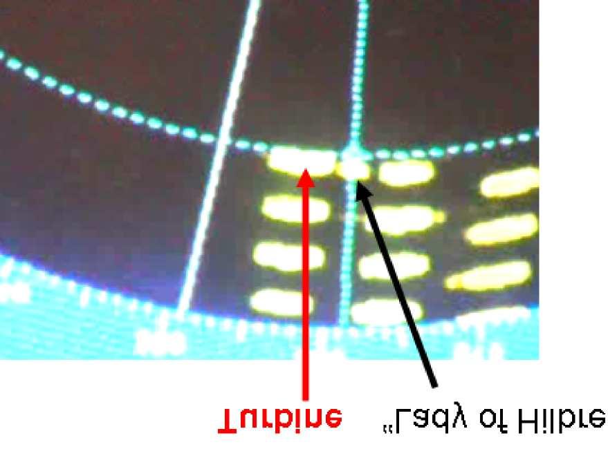
50 Figure 6-15: MCA Schematic for assessing side lobe, multiple and reflected echo effects As with all ranges closer than about 1.5 nm, side lobe echoes and multiple echoes were very strong. Side lobe echoes Multiple echoes Detection of small targets or buoyage would be extremely difficult in these circumstances. "Lady of Hilbre" at a range of 0.3 nm (550 m) Figure 6-16: Radar on 0.75 nm range and short pulse Page 50 MCA MNA 53/10/366
51 6.10 Further side lobe, reflected and multiple echoes identification Objectives and method The objectives of this trial were two fold. Firstly the spurious echoes inside the wind farm were to be examined and secondly the response of "Lill Cunningham" to a shore based radar were to be recorded (see subsection 6.12 for details of this). "Lill Cunningham" was to proceed north between turbine columns 1 to 26 and 2 to 27. This is shown in more detail in Figure Figure 6-17: Further side lobes schematic Results of the test With the set tuned correctly and with proper brilliance levels, the gain control was adjusted to various levels. Within the wind farm it was found that, with the radar set on the 1.5 nm range, ie. a shorter range than the length of the wind farm site, and on short pulse, significant quantities of spurious echoes were produced at all gain levels. i ii, iii iv With the gain level set higher than its optimum on this range the display was severely affected by side lobe echoes. The gain control set at its mid level, either manually or by use of the automatic gain control, would be the unit s normal level. Turning gain down to further reduce side lobe or multiple echoes would affect the detection of smaller target vessels or buoyage. With gain levels approaching zero, side lobe echoes were reduced to a minimum but, with this very low level of signal amplification, small targets and buoyage would be very difficult - if not impossible - to detect. The photographs in Figure 6-18 illustrate the effects on side lobe echoes of reducing gain manually and that obtained using the automatic gain control. It should be noted that the use of swept gain anti-sea clutter controls would also reduce gain at a specific distance from the observing vessel. MCA MNA 53/10/366 Page 51

52 Figure 6-18: Adjusting gain levels Summary Since marine radar scanners are not perfect directional propagators some emissions occur in directions other than the main beam. These are not usually critical unless strongly reflecting surfaces are in close proximity, when spurious echoes may be received from directions other than that of the main radar beam. These were found to occur in a number of radar systems at ranges of less than 1.5 nm (2800 metres) from the wind farm. This happened in both the X band and S band type tested and approved radars carried in the "Norbay". The effects were greater on S band (See subsection 6.14). At a range of 0.6 nm (1100 metres) from the turbines "Norbay" reported very heavy spurious echoes on S-band radar. This effect was also examined on the X band radar of the Rhyl lifeboat "Lill Cunningham". Within the windfarm where the maximum distance from the nearest WTG is always less than 430 metres, the side lobe effect with normal gain levels was very heavy. This would make the detection of other craft or buoyage difficult, and impossible in some conditions. Page 52 MCA MNA 53/10/366
53 Reducing gain levels would reduce side lobe effects but would also reduce the response of those vessels for which a lifeboat might be searching, or from which other craft might be seeking to keep clear. The experience of the "Lill Cunningham" was that, to reduce side lobe effects to zero, the gain had to be set at its minimum level. At this level small craft would not be detected, especially if they were close to WTGs (see shadow areas and bearing / range discrimination in subsections 6.2 and 6.4), in rain, or in sea clutter. Setting the gain control at its mid level or applying the automatic gain control when less than about 500 metres from WTGs resulted in a significant proportion of spurious echoes. For RNLI vessels search and rescue (SAR) operations this has obvious implications. For other vessels there could be problems in collision avoidance. This would apply particularly to large or high speed vessels in which there might be a requirement to keep radars on longer range scales and with normal gain levels, when in the vicinity of wind farms, so as to plan required manoeuvres in ample time. This would apply particularly to vessels within higher density shipping lanes which might be near to larger Round 2 offshore wind farms, and which might have joining or crossing traffic or buoyed waypoints. MCA have proposed that a research project should be undertaken to look at improvements in the detection and discrimination of small targets, supporting the need highlighted at IMO NAV 50 in June 2004, following high-profile incidents such as the loss of the High Speed Craft (HSC) "Sleipner", in which there were sixteen deaths. It might be possible to use the results of this project to examine the overall effects of offshore wind farms on the detection of small craft, obstructions and buoyage. This could also provide further guidance to the clearance of wind farm boundaries from traffic routes or from critical buoyage and its data could be included in the proposed DTI navigational risk assessment methodology referred to in the Executive Summary New international standards for type tested marine radars will become available after The effects of offshore wind farm structures on these will need to be assessed Sea and rain clutter within the wind farm High winds and swell will produce sea clutter within the wind farm which will itself interfere with the detection of targets. The presence of WTGs against which waves might break may increase the overall sea clutter, which can be reduced by the swept gain control on basic radar equipment. Again, however, the reduction of gain may reduce detection and tracking abilities. Tripod foundations may produce greater sea clutter than monopiles. Rain clutter is produced by reflection from water droplets and, again in simple radar systems, its effect is reduced by employing fast time constants (FTC). There is generally a noticeable reduction in detection abilities when FTC is employed. An example of a radar display showing rain clutter near to the wind farm is shown in Figure At all times when the trials were being undertaken, there were light winds, calm seas MCA MNA 53/10/366 Page 53

54 Figure 6-19: Precipitation effects and clear visibility. This had some advantages in that the vessels involved were able to look at effects close to turbines. However, because of these conditions, the effects of sea clutter and precipitation in combination with the wind farm s own interference effects were not able to be examined. Benchmarks for the range of first detection in clutter conditions are to be included in the MCA project mentioned above, clutter environments for both sea state and rainfall and as combinations of these being defined MCA tests on the effects of wind farm structures on shore based radars Overview The objectives were to inform the operation of VTS and Port approach radar systems in the vicinity of offshore wind farms. Two radar systems were used in these trials, one being the mobile radar unit kindly loaned to the MCA by the Environment Agency and the other being the radar unit at Gwaenysgor, above Prestatyn. This unit is used by BHP Billiton to monitor traffic around the Douglas oil field and the Hamilton gas field, these being sited some 7.5 nm north of the North Hoyle wind farm. Raw and filtered radar data were recorded by the Denbridge Marine APX-8000 system. "Lill Cunningham" and "Lady of Hilbre" carried out the exercises described in the foregoing on July 21st and 22nd 2004, testing their on board systems to determine if they were degraded in any way by the wind farm. During this time, their movements were being monitored and recorded by shore based radars. The shore radar sites were Page 54 MCA MNA 53/10/366
55 Figure 6-20: North Hoyle wind farm with radar positions (Not to scale) MCA MNA 53/10/366 Page 55

56 as illustrated in Figure 6-20, the mobile radar first being located at a site almost in line with turbine column 5 to 30 and then being relocated near to the BHP Billiton radar. The recording equipment was, on the following day, then transferred from the mobile radar unit to the BHP Billiton unit. The mobile radar was first sited along the promenade and access road next to the Prestatyn yacht club, where it had a scanner height of approximately 6 metres above sea level and was 4 nm from the wind farm Results from the first radar position The results from the first radar position are shown in Figure 6-21 and Figure In Figure 6-21 the radar is on medium pulse and the turbine echoes are displayed as approximately 600 metres in azimuth and 70 metres down range. Whilst in Figure 6-22 the radar is on long pulse and the displayed wind farm echo sizes are respectively 610 metres by 300 metres. The eastern met. mast shows clearly, but with a significantly narrower azimuth than the turbines. It should be noted that it was very difficult, with the radar at this low height (about 6m above sea level), to detect small targets within the wind farm itself. Figure 6-21: Radar is on medium pulse On the medium pulse length the transmitted power was such that the eastern anemometer mast was only just detectable, but neither lifeboat could be seen on the display. On the long pulse length the turbines were very prominent, but, as with the lifeboats own radars, the boats could only be detected rarely by the shore radar. As with the RNLI lifeboat radars, there was no discernable variation in the magnitude of the turbine response with respect to blade disc direction or rotation. Had the blade disc direction varied to a significant extent during the trials, it might have been possible to accurately measure any variations in across range response distances. Page 56 MCA MNA 53/10/366


57 Figure 6-22: Radar set to long pulse length An example of the detection of the "Lady of Hilbre" is illustrated in Figure It can be noted in the figure that the vessel can just be detected between turbines 20 and 25. The "Lady of Hilbre" can just be detected between turbines 20 and 25 Figure 6-23: Detection of the "Lady of Hilbre" MCA MNA 53/10/366 Page 57

58 6.13 Mobile radar at higher location The mobile radar was then taken close to the BHP Billiton radar site at Gwaenysgor. At this site it was approximately 200 metres above sea level and 5.2 nm from the wind farm. In Figure 6-24 it can be seen that the detection of small targets was not greatly improved but the discrimination of the western meteorology mast from turbine 26 and the service vessel immediately south of turbine 6 was apparent. New mobile radar site (close to BHP Billiton site) Figure 6-24: Mobile radar at Gwaenysgor 6.14 BHP Billiton radar The radar recording unit was then transferred to the BHP Billiton Raytheon radar unit, close by. The position of this radar relative to the wind farm is shown in Figure The displayed sizes of the North Hoyle WTGs from Gwaenysgor appear significantly greater than theoretical calculated size, the across range echo size being around 610 metres at a range of 5.2 nm and the down range depth being around 200 metres. For ARPA or VTS / Port radar tracking systems the effects may be that tracking vessels within or close to wind farms may be problematic. This was found to be the case with the "Norbay" ARPA systems and with the BHP Billiton tracking system at Gwaenysgor. The raw radar image with high persistence level is shown in Figure Using a high persistence level the recorded data would, when filtered, detect targets if not directly behind turbines. This is illustrated in Figure When target vessel to the North of the wind farm was clear by approximately 1500 metres, its response was increased noticeably, as is shown in Figure Page 58 MCA MNA 53/10/366


59 Figure 6-25: Relative Position of BHP Billiton Raytheon radar head at Gwaenysgor Figure 6-26: Raw radar with high persistence level MCA MNA 53/10/366 Page 59


60 Figure 6-27: Filtered display - high persistence Figure 6-28: Target lifeboats clear of the wind farm 6.15 MCA larger vessel radar detection and ARPA evaluation Overview To evaluate the effects of wind farm structures on type-tested radars using larger scanner sizes. The equipment required for this trial was: Larger vessel, with type-tested MCA approved radar equipment; Smaller vessel fitted with a radar reflector, carrying out a detection exercise described in the following paragraphs. In the week following the trials undertaken by the two lifeboats, on July 29th 2004, the P & O passenger / cargo ferry MV "Norbay" was used to make a passage around and through the wind farm. During this time her officers observed the wind farm service vessel "Fast Cat" which was carrying out the detection exercise through the wind farm. The "Norbay" was herself monitored by the Mersey Docks and Harbour Board port radar, sited at Seaforth Dock, Liverpool and by the BHP Billiton radar at Gwaenysgor. The courses followed during the trial are shown in Figure Page 60 MCA MNA 53/10/366
61 "Norbay" was fitted with Raytheon X and S-band radars, each with Raytheon M34 Automatic Radar Plotting Aids (ARPA). "Fast Cat" was fitted with a Firdell Blipper radar reflector. "Norbay" also monitored her communications systems, her Automatic Identification System (AIS) and her Global Positioning System (GPS) equipment whilst within and close to the wind farm (see the Masters exercise report in sub-subsection ). "Norbay" has a length overall of metres, beam 23.4 metres and 17,464 Gross Tonnage. Two photographs of the "Norbay" can be seen in Figure Whilst a photograph of the "Fast Cat" and its radar reflector are shown in Figure Figure 6-29: Larger vessel trials schematic MCA MNA 53/10/366 Page 61


62 Figure 6-30: MV "Norbay" Figure 6-31: "Fast Cat" and its "Blipper" radar reflector 6.16 Results of the Trials The results are presented in Figure 6-32 to Figure In Figure 6-32 the raw radar display as "Norbay" begins to pass at a distance of 800 metres across the northern boundary of the wind farm is shown. Whilst in Figure 6-33 the filtered recording of "Norbay" passing turbine 30 is presented. Note that in both the raw and processed radar displays, strong multiple echoes of turbines are visible. As the "Norbay" passes turbine 29 multiple echoes are still visible as is shown in Figure 6-34 and in Figure 6-35 as the vessel passes turbine 28. In Figure 6-36 the raw radar display, as the "Norbay" rounds NW corner of the wind farm, shows heavy multiple and reflected echoes. In Figure 6-37 the filtered display, with high persistence is shown. As the "Norbay" leaves the wind farm it resumes its passage with a hull aspect of about 150 degrees. No multiple echoes are see at this aspect, but some small reflected echoes are visible. Page 62 MCA MNA 53/10/366


63 Figure 6-32: Raw radar data as the "Norbay" passes turbine 30 at a range of 800 metres Figure 6-33: Filtered radar data as the "Norbay" passes turbine 30 at a range of 800 metres Figure 6-34: Filtered radar data as the "Norbay" passes turbine 29 MCA MNA 53/10/366 Page 63


64 Figure 6-35: Raw radar data as the "Norbay" passes turbine 28 Figure 6-36: Raw radar data as the "Norbay" rounds NW corner of the wind farm Figure 6-37: Filtered radar data as the "Norbay" leaves the wind farm Page 64 MCA MNA 53/10/366
65 The Mersey Docks and Harbour Board long range radar This radar, at a range of 14 nautical miles (26 km) from the wind farm, successfully tracked the "Norbay" during her passage around and through the turbine array, with the Norcontrol VOC500 tracking and recording equipment. However, no smaller vessels could be detected or tracked at this range Reflected and multiple echoes in general Since the WTGs are strongly reflecting when vessels and / or shore based radars are close by they can produce significantly interfering reflected and multiple echoes. Reflected echoes occur when signals are reflected at an angle from one structure to another and returned to the radar via the same route. The latter target will then be indicated on the display in the direction of the initial reflecting surface, and at a range equivalent to the total distance from radar to initial reflector plus the distance from it to the second surface.the target may additionally be indicated at its correct range and bearing. This effect occurred within the wind farm when signals were reflected between WTGs. Multiple echoes occur similarly when two strongly reflecting surfaces reflect signals backwards and forwards between them, such that echoes of the latter target occur a number of times behind the initial reflecting target, the distance between each such spurious echo being that of the two targets. This was found to occur with the BHP Billiton radar sited at Gwaenysgor, whose purpose is to monitor traffic in and around the Douglas and Hamilton oil and gas fields. These fields lie 14 nm from the radar site, the North Hoyle wind farm lying in the same direction but only 5.2 nm from the radar site. The Gwaenysgor radar scanner is 200 metres above sea level. When the P & O ferry "Norbay" was proceeding along the northern boundary of the wind farm and at a distance of around 800 metres from it (as indicated by the radar ranges) very strong multiple echoes were found to occur on its far side (see subsection 6.16) At this time the "Norbay" was almost broadside on to the scanner direction, such that its reflected echoes to the WTGs would be maximum. Both of these effects may have implications for port approaches, Vessel Traffic Services, search and rescue, and for collision avoidance. As with side lobe echoes, the effects can be reduced by turning down the receiver gain, but again with the penalty of reducing the displayed response of other vessels or buoyage. For radars used in Vessel Traffic Services, for monitoring infringements, or in port approaches the effects of multiple and reflected echoes may be significant, particularly where a number of vessels may be required to pass or anchor close to a wind farm boundary. However, they may be reduced by the careful siting of shore radars relative to shipping routes and wind farms, or if necessary, by using radars at different sites to resolve ambiguities. Previous laboratory studies have indicated that there is high potential for such reflected signals to trigger Racons when a turbine is within 1000 metres of them. No Racons MCA MNA 53/10/366 Page 65
66 were at this distance from the North Hoyle turbines and therefore this could not be substantiated. However, if Racons were to be considered for use in marking wind farms, this effect should be determined. Trinity House Lighthouse Service, which maintains a number of Racons, have agreed to investigate this Report from the Master, MV "Norbay" mv.norbay MCA RESEARCH INTO CLOSE NAVIGATION AROUND THE NORTH HOYLE WIND FARM. Vessel s route : West along North edge of wind farm approx. 300m off line of turbines, South along Western edge approx. 300m off line of turbines then East to midway between turbines 2 and 3 then North between rows of turbines to resume passage to Dublin. Weather on scene : Light winds, strong ebb tide fine and clear. Bridge team : Master M. Ingham Rel. Master J. Moore Ch. Officer D. McAuley 2nd Officer A. Saulnier Radar Types : Observations : 1 x Raytheon M34 Arpa 3cm 1 x Raytheon M34 Arpa 10cm Internal and external radio communications satisfactory. AIS fully satisfactory. All navigational equipment functioned satisfactorily. Radar observations : 1. On long pulse experienced no definition between close targets. 2. Definition on 3cm radar better than the 10cm set. 3. Experienced difficulties in plotting targets running close to turbines as target swap to larger echo (turbine) occurred before plot had been calculated. 4. Small targets could only be identified when they were at a distance of more than 300m off the turbines. 5. Experienced numerous false echoes close to the turbines when about 1.5 miles off. 6. Echoes of targets on 10cm radar joined up in sweep at a distance of 0.6 miles off. 7. When vessel and targets running N/S along columns of turbines there were no problems experienced in plotting targets with both 3 and 10cm sets so long as the targets remained over 300m from turbines. However, the strength of the echo on the 3cm set faded the closer the target became. Page 66 MCA MNA 53/10/366
67 7 MCA navigation system trials 7.1 The Global Positioning System (GPS) Basic GPS operated satisfactorily in all areas near to and within the wind farm with no change in signal to noise ratios, indicating that there was no interference being caused to the UHF satellite signals by the wind farm generators. The lifeboat crew did report that the Magnavox "Professional" receiver used in the "Lill Cunningham" would not accept Differential GPS signals whilst in the wind farm. The differential transmitter used in this area is sited at Point Lynas, Anglesey, using the low frequency of KHz. However, no other vessel has reported difficulties with the reception of Differential signals and theory suggests that wind farm structures should not affect them. Other vessels have been asked to report any failures. 7.2 Magnetic compasses No problems with respect to magnetic compasses were reported. However, small vessels with simple magnetic steering and hand bearing compasses should be wary of using these close to WTGs - as of course with any structure in which there is a large amount of ferrous material. Note : Under the DTI Renewable Energy Fund projects to be undertaken on offshore wind farms and other offshore renewable energy installation (OREI) proposals, the magnitudes and frequencies of electromagnetic and acoustic emissions from such installations will be monitored. These data could also be used to infrom navigational and other off-shore concerns. 7.3 Loran C Trial Trial overview and objectives The objectives of this trial were to see whether the wind farm structures would affect low frequency signals in general and degrade the use of Loran C equipment in their vicinity. Since none of the participating vessels carried Loran C, portable equipment was obtained from Trinity House Lighthouse Service and set up on the "Lill Cunningham". A photograph of the Loran C receiver is shown in Figure 7-1 below. The equipment was set up before entering the wind farm and, during exercises within the farm, connection with various chains was attempted. MCA MNA 53/10/366 Page 67
, is - currently at least - the electronic navigation fall back system if GPS were to fail.")
68 Figure 7-1: Furuno LC- 90 Loran C receiver Results of the trial Loran C, which operates at Low Frequency (100 KHz), is - currently at least - the electronic navigation fall back system if GPS were to fail. It was not fitted in any of the vessels used in the trials - being mostly used in ships on and near the US coast, although some GPS receivers have built-in Loran C software - and therefore a carry-aboard Foruno LC -90 system was used in the "Lill Cunningham". The system failed to operate successfully and could only lock on to the Lessay Chain transmissions. Even here, only one hyperbola could be obtained. This was, however, probably due to operational errors or the closing down of the Loop Head transmitter in the Republic of Ireland, rather than the effects of the wind farm on the received signals. The signals received jittered as would normally be expected from ground and skywave interference. Page 68 MCA MNA 53/10/366
69 7.4 MCA helicopter search and rescue systems Overview The aim of this test was to evaluate the capabilities of search and rescue helicopters in detecting and communicating with casualties within offshore wind farms. The following equipment was required: A small vessel fitted with a typical VHF radio (ideally an RNLI vessel); A search and rescue helicopter. A schematic of the trial is shown in Figure 7-2. The helicopter to approach the wind farm from a direction and at a suitable height selected by its crew. The small vessel is to be positioned alongside or very close to a turbine selected by the helicopter crew, diametrically opposite the approach direction of the helicopter. The helicopter crew will attempt to detect the vessel using its radar and to communicate via VHF using a channel selected by themselves, initially when some distance away and until directly over the vessel. The helicopter crew will determine any other trials that they might wish to undertake and that might involve the use of other vessels or shore stations. Figure 7-2: Schematic of helicopter radar trial Results of the trial There are no trials results as yet. During the original trials period, arrangements were made on three occasions for these to take place. Unfortunately on each occasion the helicopter was called out to other emergency duties and therefore the trials were cancelled. The Commanding Officer of RAF Valley SAR Flight is keen that the trials should take place and will arrange for this with the Rhyl Lifeboat crew on a mutually convenient date. HM Coastguard Holyhead MRSC will co-operate in setting up these trails. MCA MNA 53/10/366 Page 69
70 7.5 Effects of wind farm structures on non type tested radar, communications and navigation equipment The effects on the majority of recreational vessels and their radar, communications and navigation systems will be similar to those described in the foregoing, but some non type tested systems could be more adversely affected. During the short period of the MCA trials at North Hoyle no recreational craft were available to take part. However, the Royal Yachting Association (RYA) has asked its members to report any significant data. The letter is shown in Appendix A. Page 70 MCA MNA 53/10/366
71 8 Conclusions and recommendations 8.1 MCA trials MCA s programme was intended to assess the effect of the wind farm structures on marine systems in operational scenarios. The trials assessed all practical communications systems used at sea and with links to shore stations, shipborne and shore-based radar, position fixing systems, and the Automatic Identification System (AIS). The tests included basic navigational equipment such as magnetic compasses. The effects on the majority of systems tested by the MCA were not found to be significant enough to affect navigational efficiency or safety, and an on-going collection of data on such systems is expected to prove these conclusions. Some reported effects, such as those on short range radio devices, will be further investigated as will some scenarios which could not be assessed during the trials period, such as helicopter search and rescue operations within wind farms. The only significant cause for concern found by the MCA during the trials was the effect of wind farm structures on shipborne and shorebased radar systems. It was determined that the large vertical extent of the wind turbine generators returned radar responses strong enough to produce interfering side lobe, multiple and reflected echoes. While reducing receiver amplification (gain) would enable individual turbines to be clearly identified from the side lobes - and hence limit the potential of collisions with them - its effect would also be to reduce the amplitude of other received signals such that small vessels, buoys, etc., might not be detectable within or close to the wind farm. Bearing discrimination was also reduced by the magnitude of the response and hence the cross range size of displayed echoes. If on passage close to a wind farm boundary or within the wind farm itself, this could in some circumstances affect a vessel s ability to fully comply with Rules 6, 7 and 19 of the International Regulations for the Prevention of Collisions at Sea and might also affect the performance of its automatic radar plotting aid (ARPA). With respect to the multiple and reflected echoes produced when wind farm structures lie between the observing radar and a relatively high sided vessel, gain reduction will have similar effects to those described above. If, as in the trial undertaken, a shore or platform based radar is intended to detect and track traffic in port approaches, Vessel Traffic Systems or in the proximity of offshore oil or gas installations, the effects could be significant. Recommendations from these trials are that: This report should be made feely available to all interested parties. Information appropriate to the safety of life at sea, such as recommendations with respect to navigating or carrying out activities such as fishing within or close to wind farms, should be promulgated as necessary by the use of Marine Guidance Notes, Marine Information Notes, Merchant Shipping Notices, etc. the siting of wind farm boundaries from recognised marine traffic routes should be determined in consultation with MCA HQ and other stakeholders using a MCA MNA 53/10/366 Page 71
72 recommended risk assessment methodology, prior to the submission of consent applications. Similarly the location and relocation of fixed radar surveillance systems should be determined in consultation with relevant organisations. Further work to be done, as for example identified in the report with respect to adverse weather conditions, helicopter search and rescue operations, short range radio systems, non type-tested systems, etc., should be carried out as soon as practical. The results of such research should be promulgated where significant. The collation of data with respect to all offshore renewable energy installations (OREI) should be an ongoing activity. 8.2 QinetiQ trials Four trials, covering the areas of GPS, VHF communications and radar tracking and radar clutter were performed by QinetiQ. The QinetiQ GPS trial involved traversing previously defined courses through and around the wind farm. Along each course, the number of satellites visible to two different GPS systems (a Garmin 152 and a Garmin GPSIII) and the position of the ship were recorded. Our results show that on average between 8 and 11 satellites were visible at any one time providing accurate positioning to within 5 metres. The effect of wind turbines on VHF communications was investigated by QinetiQ using a hand-held VHF transceiver that was run in series with an adjustable attenuator. A link margin of 1 db was achieved in free-space (away from any turbines). This required an attenuation of 16dB to be added to the transceiver. To explore the shadow region behind the wind turbines, four link margins, 2dB, 3dB, 4dB and 5dB were used. These link margins correspond to a total attenuation of 15dB, 14dB, 13dB and 12dB added to the transceiver. The closest approach to turbine 21 was 500 metres and approximately 5m behind turbine 26. As expected the depth of shadow was greater when closer to a turbine. When behind turbine 21 the shadow was found to be approximately 2dB to 3dB lower than the attenuation needed to give a 1dB link margin in free space. For turbine 26 the shadow was deeper due to the closer proximity of the VHF system. It was found that behind turbine 26 the depth of shadow was approximately 10dB below the link margin in free space. The shadow depths are shallower than predicted theoretically confirming the worst case expectations of the theoretical work. The QinetiQ radar shadowing trials provided very little evidence that shadowing of targets would present any significant problems. In particular the shadowing observed was, like the VHF trials, less than predicted in the theoretical study. Clutter in the radar display due to the presence of wind turbines was found to be quite considerable. Both ring-around and false plots (side lobe and spurious echoes) were observed. The observed problems could be suppressed successfully by using the gain and range settings of the radar. However, this may have the unwanted side-effect of no longer being able to detect some small targets. Page 72 MCA MNA 53/10/366
73 8.3 Summary Most of the effects of offshore wind farm structures on the operational use of marine radar, communications and navigation systems do not significantly compromise marine navigation or safety. Where there are questions about specific systems they will continue to be monitored and assessed when possible. There are however some concerns about the use of both shipborne and shorebased radar in the proximity of wind farms. Wind farm structures generally have high vertical extents and therefore will return very strong responses when observing radars are close. The magnitude of such responses will vary according to transmitted radar power and proximity to the structures but may affect both the visual detection of targets and the effective operation of automatic radar plotting aids (ARPA). These effects can be mitigated by vessels keeping well clear of wind farms in open water or, where navigation is restricted, keeping the wind farm boundaries at suitable distances from established traffic routes, port approaches, routing schemes, etc. With respect to shorebased or offshore platform based systems, the careful siting of radar scanners in relation to traffic routes and wind farm configurations should enable any degrading effects to be minimised. The overall results are summarised as: i ii iii iv v Global Positioning System (GPS) No problems with basic GPS reception or positional accuracy were reported during the trials. Magnetic compasses The wind farm generators and their cabling, interturbine and onshore, did not cause any compass deviation during the MCA trials. As with any ferrous metal structure, however, caution should be exercised when using magnetic compasses close to turbine towers. Loran C Although a position could not be obtained using Loran C in the wind farm area, the available signals were received without apparent degradation. Helicopter radar and communications systems These trials were not carried out due to helicopter call-outs to emergencies on the trial days. The emergency services are keen that they should be undertaken when convenient with the co-operation of HM Coastguard Holyhead MRSC. VHF and other communications The wind farm structures had no noticeable effects on any voice communications system, vessel to vessel or vessel to shore station. These included shipborne, shorebased and hand held VHF transceivers and mobile telephones. Digital selective calling (DSC)was also satisfactorily tested. The VHF Direction Finding equipment carried in the lifeboats did not function correctly when very close to turbines and the BHP telemetry link was similarly reported to suffer interruptions. MCA MNA 53/10/366 Page 73
74 vi vii viii The Automatic Identification System (AIS) carried aboard MV "Norbay" and monitored by HM Coastguard MRSC Liverpool was fully operational. Small Vessel radar performance. 1. The wind turbine generators (WTG) produced blind and shadow areas in which other turbines and vessels could not be detected unless the observing vessel was moving. 2. Detection of targets within the wind farm was also reduced by the cross and down-range responses from the WTGs which limited range and bearing discrimination. 3. The large displayed echoes of WTGs were due to the vertical extent of the turbine structures. 4. These returned strong responses from sectors of the main beam outside the half power (-3dB) points and the side lobes outside 10 from the main beam. 5. Although such spurious echo effects can be limited to some extent by reducing receiver amplification (gain) this will also reduce the amplification of other targets, perhaps below their display threshold levels. 6. Sea and rain clutter will present further difficulties to target detection within and close to wind farms. Weather conditions at the time of the trials were such that these effects could not be examined. Shore based radar performance 1. Short range performance (less than 6 nm) When a small shore based radar was sited such that the height of its antenna was about six metres above sea level, its performance with respect to small vessels was similar to that of the vessel-mounted systems in terms of range and bearing discrimination and target detection within the wind farm. When moved to a height of 200 metres above sea level there was an improvement in range discrimination. When the higher powered and narrower beam width BHP Billiton radar was used, at the same height, the visual detection of targets within, and beyond, the wind farm was again improved. 2. Larger vessel detection A larger vessel was easily detected within and beyond the wind farm. However, while it was broadside on to the direction of the shore radar, reflections from the turbines produced strong multiple echoes. At an oblique aspect to the radar, multiple echoes did not occur, but some reflected echoes were observed. 3. Long range radar (more than 12 nm) When the wind farm was observed at long range by the Mersey docks and Harbour Board radar the vessel was easily detected and tracked Page 74 MCA MNA 53/10/366
75 ix x Radar and ARPA carried on larger vessels As with small vessel radars, range and bearing discrimination were affected by the response from the WTGs. Definition was less on S band radar than on X band. Numerous spurious echoes from side lobes and reflections were reported by MV "Norbay" starting at a range of about 1.5 nm. The ship s ARPA had difficulty tracking a target vessel within the wind farm due to target swop to the stronger response. This substantiated a similar report with respect to the BHP Billiton radar s own tracking system Non type-tested radar, communications and navigational equipment The effects on such systems will be similar to those tested during the trials but will vary individually with respect to transmitted power, antenna performance, radar beam width, etc. The Royal Yachting Association is assisting MCA by providing ongoing information through the experiences of its membership. MCA MNA 53/10/366 Page 75

76 A RYA letter NORTH HOYLE WIND FARM Assessing effects on recreational craft communications and radar? PLEASE TAKE PART AND FEED BACK YOUR EXPERIENCES The RYA is helping the MCA in testing the impact of offshore wind turbines on communication and radar equipment. Whilst they can see the effect on high tech equipment carried on board the MCA vessels, we need to assess the effect on small craft equipment, e.g., VHF, small boat radar, etc. We have been asked to report back to the MCA the effects on recreational equipment which can only be done by those who use the area - your involvement in this is important. If you are sailing past the area, please do take part. Ideally we are looking for two medium size vessels (30 foot) - but reports from individual vessels will also be valuable - fitted with radar and VHF, also Loran C if available. We need the vessels to enter the wind farm area, record the display on their radar - ideally with a digital camera - test VHF communications between vessels and also with the coastguard at Holyhead. What to do: 1 Before entering the wind farm area, please call up the Wind Farm Operations Manager, Mike Bradley ( ) to check whether any maintenance vessels are operating. If maintenance vessels are operating please keep 500m clear of them 2) Approaching the wind farm area look at the effects on your radar screen, ideally take a digital picture of them, or sketch them out. If you turn the signal down to avoid distortion of the signal, ensure you would still be able to pick up other small vessels 30 Before entering the wind farm area, call the Holyhead Coastguard, District Controller, Jim Paton ( ) and tell him what you are doing and carry out a (VHF) radio check outside the wind farm area. If you have a hand held you may also want to carry out the exercise with this too. 4) Once inside the wind farm area, look again at the effect on your radar screen and report as in (2) 5) Once inside the wind farm area, carry out a second radio check with the Coastguard. 6) If you are sailing with two vessels, get behind the turbines out of direct sight of one another and test radio communications with one another. You can also check to see the effects on your radar. Page 76 MCA MNA 53/10/366
77 7) Please also report the type of equipment you have on board (VHF and radar), height of VHF mast, proximity to the turbines when you carried out the recordings. 8) Then send your findings back to Susie Tomson (Planning and Environmental Officer) at the RYA either by phone, or post. Contact details: Susie Tomson, RYA House, Ensign Way, Hamble, Hants, SO31 4YA. Please call if you have any queries my direct line is Please feel free to add any other comments on your experience of sailing through the area. THANK YOU FOR YOUR HELP AND COOPERATION MCA MNA 53/10/366 Page 77
 Racal Decca Bridgemaster 250 series specifications: Magnetron peak power Frequency Pulse lengths / prf (nominal) Racal Decca antenna")
78 B Radar specifications B.1 Environment Agency radar (mounted in Ford Transit van) Racal Decca Bridgemaster 250 series specifications: Magnetron peak power Frequency Pulse lengths / prf (nominal) Racal Decca antenna specifications: Aperture size horizontal beam width vertical beam width sidelobes within 10 of beam sidelobes outside 10 of beam Polarisation Rotation speed 10kW 9410 MHz ± 30MHz 0.05 µs 1200 Hz µs 1200 Hz µs 600 Hz 4 ft (1.22 m.) 2 (to -3 db) 24 (to -3 db) -23 db -30 db Horizontal 28 rpm Page 78 MCA MNA 53/10/366
 horizontal beam width 1.")
79 B.2 Mersey class lifeboat radars JRC JMA 3910 series specifications: Magnetron peak power 10 kw Frequency 9410 MHz ± 30MHz Pulse lengths 0.08 µs (nominal) 0.2 µs 0.4 µs 0.8 µs JRC antenna specifications: Aperture size 4 ft (1.22 m) horizontal beam width 1.9 (to -3 db) vertical beam width 25 (to -3 db) sidelobes within 10 of beam -23 db sidelobes outside10 of beam -26 db Polarisation Horizontal Rotation speed 25 rpm MCA MNA 53/10/366 Page 79

80 B.3 BHP Billiton Gwaenysgor Radar (ashore above Prestatyn) Raytheon series specifications: Magnetron peak power Frequency Pulse lengths / prf (nominal) Raytheon antenna specifications: Aperture size horizontal beam width vertical beam width sidelobes within 10 of beam sidelobes outside10 of beam Polarisation Rotation speed 25 kw 9410 MHz ± 30MHz 0.06 µs 3000 Hz 0.25 µs 2000 Hz 0.5 µs 1000 Hz 1.0 µs 750 Hz 12 ft (3.66m) 0.7 (to -3dB) 23 (to -3dB) -30 db -? db Horizontal 22 / 26 rpm Page 80 MCA MNA 53/10/366
CHAPTER 1 INTRODUCTION
 1 CHAPTER 1 INTRODUCTION In maritime surveillance, radar echoes which clutter the radar and challenge small target detection. Clutter is unwanted echoes that can make target detection of wanted targets
RECOMMENDATION ITU-R M * Technical characteristics for search and rescue radar transponders
 Rec. ITU-R M.628-4 1 RECOMMENDATION ITU-R M.628-4 * Technical characteristics for search and rescue radar transponders (Questions ITU-R 28/8 and ITU-R 45/8) (1986-1990-1992-1994-2006) Scope This Recommendation
Annex 11 to Working Party 5B Chairman s Report WORKING DOCUMENT TOWARDS A PRELIMINARY DRAFT NEW REPORT ITU-R M.[SNAP]
![Annex 11 to Working Party 5B Chairman s Report WORKING DOCUMENT TOWARDS A PRELIMINARY DRAFT NEW REPORT ITU-R M.[SNAP]](/thumbs/92/108810182.jpg "Annex 11 to Working Party 5B Chairman s Report WORKING DOCUMENT TOWARDS A PRELIMINARY DRAFT NEW REPORT ITU-R M.[SNAP]") Radiocommunication Study Groups Source: Document 5B/TEMP/287 Annex 11 to Document 5B/617-E 29 November 2010 English only Annex 11 to Working Party 5B Chairman s Report WORKING DOCUMENT TOWARDS A PRELIMINARY
Radiocommunication Study Groups Source: Document 5B/TEMP/287 Annex 11 to Document 5B/617-E 29 November 2010 English only Annex 11 to Working Party 5B Chairman s Report WORKING DOCUMENT TOWARDS A PRELIMINARY
RESOLUTION MSC.278(85) (adopted on 1 December 2008) ADOPTION OF THE NEW MANDATORY SHIP REPORTING SYSTEM "OFF THE COAST OF PORTUGAL - COPREP"
 (adopted on 1 December 2008) ADOPTION OF THE NEW MANDATORY SHIP REPORTING SYSTEM OFF THE COAST OF PORTUGAL - COPREP") MSC 85/26/Add.1 RESOLUTION MSC.278(85) SYSTEM OFF THE COAST OF PORTUGAL COPREP THE MARITIME SAFETY COMMITTEE, RECALLING Article 28 of the Convention on the International Maritime Organization concerning
MSC 85/26/Add.1 RESOLUTION MSC.278(85) SYSTEM OFF THE COAST OF PORTUGAL COPREP THE MARITIME SAFETY COMMITTEE, RECALLING Article 28 of the Convention on the International Maritime Organization concerning
NZQA registered unit standard version 2 Page 1 of 5
 Page 1 of 5 Title Use marine radar on a restricted limits vessel Level 3 Credits 10 Purpose People credited with this unit standard are able to: relate the operating principles and conditions of marine
IHO Colours & Symbols Maintenance Working Group (C&SMWG) 15th Meeting, BSH, Rostock, Germany, 2-4 May 2005
 15th Meeting, BSH, Rostock, Germany, 2-4 May 2005") CSMWG15-INF2 IHO Colours & Symbols Maintenance Working Group (C&SMWG) 15th Meeting, BSH, Rostock, Germany, 2-4 May 2005 Ref: HA405/004/033-01 NOTE: this is an internal document of the UKHO and is supplied
CSMWG15-INF2 IHO Colours & Symbols Maintenance Working Group (C&SMWG) 15th Meeting, BSH, Rostock, Germany, 2-4 May 2005 Ref: HA405/004/033-01 NOTE: this is an internal document of the UKHO and is supplied
ROUTEING OF SHIPS, SHIP REPORTING AND RELATED MATTERS. New traffic separation schemes and two-way routes in Norra Kvarken
 E SUB-COMMITTEE ON SAFETY OF NAVIGATION 57th session Agenda item 3 NAV 57/3/7 11 March 2011 Original: ENGLISH ROUTEING OF SHIPS, SHIP REPORTING AND RELATED MATTERS New traffic separation schemes and two-way
A10 Electronic Interference: Application 2 - LBHF
 A10 Electronic Interference: Application 2 - LBHF Addendum to the Environmental Statement Volume I January 2012 Introduction A10.1 This Chapter of the Addendum to the June 2011 Environmental Statement
RESOLUTION A.820(19) adopted on 23 November 1995 PERFORMANCE STANDARDS FOR NAVIGATIONAL RADAR EQUIPMENT FOR HIGH-SPEED CRAFT
 adopted on 23 November 1995 PERFORMANCE STANDARDS FOR NAVIGATIONAL RADAR EQUIPMENT FOR HIGH-SPEED CRAFT") INTERNATIONAL MARITIME ORGANIZATION A 19/Res. 820 15 December 1995 Original: ENGLISH ASSEMBLY 19th session Agenda item 10 NOT TO BE REMOVED \ FROM THE IMO LIBRARY RESOLUTION A.820(19) adopted on 23 November
INTERNATIONAL MARITIME ORGANIZATION A 19/Res. 820 15 December 1995 Original: ENGLISH ASSEMBLY 19th session Agenda item 10 NOT TO BE REMOVED \ FROM THE IMO LIBRARY RESOLUTION A.820(19) adopted on 23 November
HIGH PERFORMANCE MARITIME. em-trak S100 PRODUCTS. Antenna splitter. Product Manual. High Performance Maritime Products
 em-trak S100 MARITIME PRODUCTS HIGH PERFORMANCE Antenna splitter Product Manual High Performance Maritime Products www.em-trak.com 201-0206:3 Contents 1 - Notices...1 1.1 - Safety warnings...1 1.2 - General
This circular summarizes the various important aspects of the LRIT system with a view to enabling companies to ensure compliance in a timely manner.
 Luxembourg, 29/10/2008 CIRCULAR CAM 02/2008 N/Réf. : AH/63353 Subject : Long-Range Identification and Tracking of Ships (LRIT) To : All ship owners, ship operators and designated persons of Luxembourg
RECOMMENDATION ITU-R BS.80-3 * Transmitting antennas in HF broadcasting
 Rec. ITU-R BS.80-3 1 RECOMMENDATION ITU-R BS.80-3 * Transmitting antennas in HF broadcasting (1951-1978-1986-1990) The ITU Radiocommunication Assembly, considering a) that a directional transmitting antenna
RESOLUTION MSC.229(82) (adopted on 5 December 2006) ADOPTION OF A NEW MANDATORY SHIP REPORTING SYSTEM "IN THE GALAPAGOS PARTICULARLY SENSITIVE SEA
 (adopted on 5 December 2006) ADOPTION OF A NEW MANDATORY SHIP REPORTING SYSTEM IN THE GALAPAGOS PARTICULARLY SENSITIVE SEA") MSC 82/24/Add.2 RESOLUTION MSC.229(82) IN THE GALAPAGOS PARTICULARLY SENSITIVE SEA AREA (PSSA) (GALREP) THE MARITIME SAFETY COMMITTEE, RECALLING Article 28(b) of the Convention on the International Maritime
MSC 82/24/Add.2 RESOLUTION MSC.229(82) IN THE GALAPAGOS PARTICULARLY SENSITIVE SEA AREA (PSSA) (GALREP) THE MARITIME SAFETY COMMITTEE, RECALLING Article 28(b) of the Convention on the International Maritime
INTERNATIONAL STANDARD
 INTERNATIONAL STANDARD IEC 60936-2 First edition 1998-10 Maritime navigation and radiocommunication equipment and systems Radar Part 2: Shipborne radar for high-speed craft (HSC) Methods of testing and
02 Issue. e-navigation News. GNSS Vulnerability. Dublin Bay Digital Diamond. e-navigation. Demonstrator Update International. e-navigation.
 CORPORATE SECURITY TEAMWORK EVENTS 02 Issue e-navigation News GNSS Vulnerability Dublin Bay Digital Diamond e-navigation Demonstrator Update International e-navigation update June 2014 www.cil.ie +353
RESOLUTION A.659(16) adopted on 19 October 1989 PROVISION OF RADIO SERVICES FOR THE GLOBAL MARITIME DISTRESS AND SAFETY SYSTEM
 adopted on 19 October 1989 PROVISION OF RADIO SERVICES FOR THE GLOBAL MARITIME DISTRESS AND SAFETY SYSTEM") INTERNATIONAL MARITIME ORGANIZATION RESOLUTION A.659(16) adopted on 19 October 1989 A 16/Res.659 30 November 1989 Original: ENGLISH ASSEMBLY - 16th session Agenda item 10 IMO RESOLUTION A.659(16) adopted
INTERNATIONAL MARITIME ORGANIZATION RESOLUTION A.659(16) adopted on 19 October 1989 A 16/Res.659 30 November 1989 Original: ENGLISH ASSEMBLY - 16th session Agenda item 10 IMO RESOLUTION A.659(16) adopted
RECOMMENDATION ITU-R M * (Questions ITU-R 28/8 and ITU-R 45/8)
") Rec. ITU-R M.628-3 1 RECOMMENDATION ITU-R M.628-3 * TECHNICAL CHARACTERISTICS FOR SEARCH AND RESCUE RADAR TRANSPONDERS (Questions ITU-R 28/8 and ITU-R 45/8) Rec. ITU-R M.628-3 (1986-199-1992-1994) The
Rec. ITU-R M.628-3 1 RECOMMENDATION ITU-R M.628-3 * TECHNICAL CHARACTERISTICS FOR SEARCH AND RESCUE RADAR TRANSPONDERS (Questions ITU-R 28/8 and ITU-R 45/8) Rec. ITU-R M.628-3 (1986-199-1992-1994) The
FURUNO DEEPSEA WORLD Class-A Universal AIS Automatic Identification System. The future today with FURUNO's electronics technology.
 R FURUNO DEEPSEA WORLD Class-A Universal AIS Automatic Identification System Model FA-100 The AIS improves the safety of navigation by assisting in the efficient navigation of ships, protection of the
FREQUENCIES FOR DISTRESS AND SAFETY, SEARCH AND RESCUE AND EMERGENCIES
 FREQUENCIES FOR DISTRESS AND SAFETY, SEARCH AND RESCUE AND EMERGENCIES Given the global nature of travel with the potential risk of accidents the international community has agreed that the use of certain
Thank you for buying this AIS antenna splitter.
 Thank you for buying this AIS antenna splitter. This product has been engineered to offer you the highest level of performance and durability and we hope that it will provide many years of reliable service.
REPORT ITU-R M Interference and noise problems for maritime mobile-satellite systems using frequencies in the region of 1.5 and 1.
 Rep. ITU-R M.764-3 1 REPORT ITU-R M.764-3 Interference and noise problems for maritime mobile-satellite systems using frequencies in the region of 1.5 and 1.6 GHz (1978-1982-1986-2005) 1 Introduction Operational
Theoretical and Practical Results from the Cloudnet Orkney Isles Ferries TVWS Pilot
 BAE Systems Naval Ships Bob Willmot BSc (Hons) CEng MIET Electronic Systems Design Engineer Theoretical and Practical Results from the Cloudnet Orkney Isles Ferries TVWS Pilot Glasgow TVWS Pilot Event,
Universidad Nacional Experimental Marítima del Caribe Vicerrectorado Académico Cátedra de Idiomas Inglés VI. Ingeniería Marítima
 Universidad Nacional Experimental Marítima del Caribe Vicerrectorado Académico Cátedra de Idiomas Inglés VI. Ingeniería Marítima UNIT II. Navigational equipment found onboard ships. Speaking. 1. Can you
Frank Heymann 1.
 Plausibility analysis of navigation related AIS parameter based on time series Frank Heymann 1 1 Deutsches Zentrum für Luft und Raumfahrt ev, Neustrelitz, Germany email: frank.heymann@dlr.de In this paper
Watcheye S AIS Splitter. manual
 Watcheye S AIS Splitter manual Thank you for buying this AIS antenna splitter. This product has been engineered to offer you the highest level of performance and durability and we hope that it will provide
Fisheries and Marine Resources (Automatic Identification System) Regulations
 Regulations") Fisheries and Marine Resources (Automatic Identification System) Regulations 2016 GN No. 116 of 2016 Government Gazette of Mauritius No. 47of 28 May 2016 THE FISHERIES AND MARINE RESOURCES ACT Regulations
Fisheries and Marine Resources (Automatic Identification System) Regulations 2016 GN No. 116 of 2016 Government Gazette of Mauritius No. 47of 28 May 2016 THE FISHERIES AND MARINE RESOURCES ACT Regulations
ECDIS ENC Accuracy. Contents. Introduction LOSS PREVENTION BRIEFING FOR NORTH MEMBER SHIPS / MAY Introduction... 1
 LOSS PREVENTION BRIEFING FOR NORTH MEMBER SHIPS / MAY 2017 ECDIS ENC Accuracy Contents Introduction... 1 ECDIS Specific Familiarisation... 2 IHO S-57... 2 ENC Data Source... 2 CATZOC and M_QUAL... 2 CATZOC
Safety Code 6 (SC6) Measurement Procedures (Uncontrolled Environment)
 Measurement Procedures (Uncontrolled Environment)") February 2011 Spectrum Management and Telecommunications Technical Note Safety Code 6 (SC6) Measurement Procedures (Uncontrolled Environment) Aussi disponible en français NT-329 Contents 1.0 Purpose...1
February 2011 Spectrum Management and Telecommunications Technical Note Safety Code 6 (SC6) Measurement Procedures (Uncontrolled Environment) Aussi disponible en français NT-329 Contents 1.0 Purpose...1
Prepared by: Anatec Limited Presented to: The Crown Estate (TCE) Date: 25 th June 2012 Revision No.: 00
 Date: 25 th June 2012 Revision No.: 00") Strategic assessment of impacts on navigation of shipping and related effects on other marine activities arising from the development of Offshore Wind Farms in the UK REZ Prepared by: Anatec Limited Presented
Strategic assessment of impacts on navigation of shipping and related effects on other marine activities arising from the development of Offshore Wind Farms in the UK REZ Prepared by: Anatec Limited Presented
RADius, a New Contribution to Demanding. Close-up DP Operations
 Author s Name Name of the Paper Session DYNAMIC POSITIONING CONFERENCE September 28-30, 2004 Sensors RADius, a New Contribution to Demanding Close-up DP Operations Trond Schwenke Kongsberg Seatex AS, Trondheim,
ROUTEING OF SHIPS, SHIP REPORTING AND RELATED MATTERS. Establishment of a Mandatory Ship Reporting System in the
 INTERNATIONAL MARITIME ORGANIZATION E SUB-COMMITTEE ON SAFETY OF NAVIGATION 48th session Agenda item 3 IMO NAV 48/3/2 11 April 2002 Original: ENGLISH ROUTEING OF SHIPS, SHIP REPORTING AND RELATED MATTERS
Neart na Gaoithe Offshore Wind Farm Environmental Statement Introduction Data Sources Guidance and Legislation
 Chapter 18 Military and Aviation 18.1 Introduction 1 This chapter provides a summary of the existing radar and military baseline conditions and an assessment of the potential impacts on these as a result
TECHNICAL COMMITTEE 80: MARITIME NAVIGATION AND RADIOCOMMUNICATION EQUIPMENT AND SYSTEMS INTERNATIONAL ELECTROTECHNICAL COMMISSION
 TECHNICAL COMMITTEE 80: MARITIME NAVIGATION AND RADIOCOMMUNICATION EQUIPMENT AND SYSTEMS INTERNATIONAL ELECTROTECHNICAL COMMISSION IEC TECHNICAL COMMITTEE 80: MARITIME NAVIGATION AND RADIOCOMMUNICATION
10 Secondary Surveillance Radar
 10 Secondary Surveillance Radar As we have just noted, the primary radar element of the ATC Surveillance Radar System provides detection of suitable targets with good accuracy in bearing and range measurement
IMO/IHO World-wide Navigational Warning Service (WWNWS)
") IMO/IHO World-wide Navigational Warning Service (WWNWS) 1 WWNWS 1972 PROPOSAL TO SET UP AN Ad Hoc IHO/IMO COMMITTEE TO DEVELOP AN INTER- NATIONALLY CO-ORDINATED SYSTEM FOR PROMULGATING LONG RANGE NAVIGATIONAL
IMO/IHO World-wide Navigational Warning Service (WWNWS) 1 WWNWS 1972 PROPOSAL TO SET UP AN Ad Hoc IHO/IMO COMMITTEE TO DEVELOP AN INTER- NATIONALLY CO-ORDINATED SYSTEM FOR PROMULGATING LONG RANGE NAVIGATIONAL
DTT COVERAGE PREDICTIONS AND MEASUREMENT
 DTT COVERAGE PREDICTIONS AND MEASUREMENT I. R. Pullen Introduction Digital terrestrial television services began in the UK in November 1998. Unlike previous analogue services, the planning of digital television
Advisory Circular AC91-5. Operation of Portable Electronic Devices (PEDs) During Flight Under IFR. Date: 1 April Subject: Author: Chris Lamain
 During Flight Under IFR. Date: 1 April Subject: Author: Chris Lamain") Advisory Circular Subject: Operation of Portable Electronic Devices (PEDs) During Flight Under IFR Date: 1 April 1997 Author: Chris Lamain AC91-5 1. GENERAL. Civil Aviation Authority Advisory Circulars
Advisory Circular Subject: Operation of Portable Electronic Devices (PEDs) During Flight Under IFR Date: 1 April 1997 Author: Chris Lamain AC91-5 1. GENERAL. Civil Aviation Authority Advisory Circulars
THE ELECTRONIC CHART DISPLAY AND INFORMATION SYSTEM (ECDIS) IN CHINA
 IN CHINA") International Hydrographic 'Review, Monaco, LXIX(2), September 1992 THE ELECTRONIC CHART DISPLAY AND INFORMATION SYSTEM (ECDIS) IN CHINA by The Research Group on ECDIS 1 Abstract This paper presents a
International Hydrographic 'Review, Monaco, LXIX(2), September 1992 THE ELECTRONIC CHART DISPLAY AND INFORMATION SYSTEM (ECDIS) IN CHINA by The Research Group on ECDIS 1 Abstract This paper presents a
Tide & Meteorological Data over AIS
 Tide & Meteorological Data over AIS E.F.Read (Ohmex Ltd) & W.S.Heaps (ABP Ltd) THSUK Hydro8 1 Background to AIS Most significant development since RADAR Positions and Timing from GPS network 12.5 Watt
OPERATIONS SEAFARER CERTIFICATION GUIDANCE NOTE SA MARITIME QUALIFICATIONS CODE SHORT RANGE CERTIFICATE (SRC)
") Page 1 of 8 Compiled by Chief Examiner Approved by Senior Radio Examiner OPERATIONS SEAFARER CERTIFICATION GUIDANCE NOTE SA MARITIME QUALIFICATIONS CODE SHORT Page 2 of 8 SHORT : OUTLINE EXAMINATION SYLLABUS
Page 1 of 8 Compiled by Chief Examiner Approved by Senior Radio Examiner OPERATIONS SEAFARER CERTIFICATION GUIDANCE NOTE SA MARITIME QUALIFICATIONS CODE SHORT Page 2 of 8 SHORT : OUTLINE EXAMINATION SYLLABUS
Technical characteristics for search and rescue radar transponders
 Recommendation ITU-R M.628-5 (03/2012) Technical characteristics for search and rescue radar transponders M Series Mobile, radiodetermination, amateur and related satellite services ii Rec. ITU-R M.628-5
Appendix 18.1: Radar and Aviation Technical Assessment
 Appendix 18.1: Radar and Aviation Technical Assessment 18.1 Military and Civil Radar 18.1.1 Primary Surveillance Radar Systems 18.1.1.1 Air Traffic Control, Air Defence and Precision Approach Radar Radar
ATTACHMENT E. How to Conduct a GMDSS Inspection.
 Page 1 of 7 NOTE: This document is an excerpt from The Report and Order In the Matter of Amendment of the Commission's Rules Concerning the Inspection of Radio Installations on Large Cargo and Small Passenger
amplification: The process of increasing the strength of a radio signal.
 GLOSSARY OF RADIO TERMS: The following is a compilation of terms and acronyms Law Enforcement officials often times hear. This information was collected from several sources. It should be used as a guide
Rec. ITU-R F RECOMMENDATION ITU-R F *
 Rec. ITU-R F.162-3 1 RECOMMENDATION ITU-R F.162-3 * Rec. ITU-R F.162-3 USE OF DIRECTIONAL TRANSMITTING ANTENNAS IN THE FIXED SERVICE OPERATING IN BANDS BELOW ABOUT 30 MHz (Question 150/9) (1953-1956-1966-1970-1992)
Shared Use of DGPS for DP and Survey Operations
 Gabriel Delgado-Saldivar The Use of DP-Assisted FPSOs for Offshore Well Testing Services DYNAMIC POSITIONING CONFERENCE October 17-18, 2006 Sensors Shared Use of DGPS for Dr. David Russell Subsea 7, Scotland
Maritime Electronics Supporting Unmanned Vessels
 EU-Japan Policy Workshop Maritime Electronics Supporting Unmanned Vessels November 11 th, 2016 TAKUO KASHIWA, Ph.D Furuno Electric Co., Ltd. Agenda Positioning Technologies for Vessel s position Technologies
IMO. Resolution A.954(23) Adopted on 5 December 2003 (Agenda item 17) PROPER USE OF VHF CHANNELS AT SEA
 Adopted on 5 December 2003 (Agenda item 17) PROPER USE OF VHF CHANNELS AT SEA") INTERNATIONAL MARITIME ORGANIZATION E IMO ASSEMBLY 23rd session Agenda item 17 A 23/Res.954 26 February 2004 Original: ENGLISH Resolution A.954(23) Adopted on 5 December 2003 (Agenda item 17) PROPER USE
INTERNATIONAL MARITIME ORGANIZATION E IMO ASSEMBLY 23rd session Agenda item 17 A 23/Res.954 26 February 2004 Original: ENGLISH Resolution A.954(23) Adopted on 5 December 2003 (Agenda item 17) PROPER USE
NEW FOR Radar. Broadband. The evolution of the radar revolution.
 NEW FOR 2011 Broadband Radar The evolution of the radar revolution. The evolution of the radar revolution. The original BR24 Broadband Radar, the frequency modulated continuous wave (FMCW) radar, has captured
Absolute Positioning by Radar
 Absolute Positioning by Radar Dr Nick Ward, Research Director General Lighthouse Authorities of UK & Ireland 14th IAIN Congress 2012, 01-03 October, 2012 - Cairo, Egypt Seamless Navigation (Challenges
Underwater noise survey during impact piling to construct the Burbo Bank Offshore Wind Farm.
 Project Title Project Number Investigators Company Report Number Underwater noise and offshore wind farms. COWRIE ACO-04-2 S J Parvin and J R Nedwell Subacoustech Ltd. 726R0103 Date 25 th October 6 Underwater
ADJACENT BAND COMPATIBILITY OF TETRA AND TETRAPOL IN THE MHZ FREQUENCY RANGE, AN ANALYSIS COMPLETED USING A MONTE CARLO BASED SIMULATION TOOL
 European Radiocommunications Committee (ERC) within the European Conference of Postal and Telecommunications Administrations (CEPT) ADJACENT BAND COMPATIBILITY OF TETRA AND TETRAPOL IN THE 380-400 MHZ
RESOLUTION MSC.230(82) (adopted on 5 December 2006) ADOPTION OF AMENDMENTS TO THE EXISTING MANDATORY SHIP REPORTING SYSTEM "IN THE STOREBÆLT (GREAT
 (adopted on 5 December 2006) ADOPTION OF AMENDMENTS TO THE EXISTING MANDATORY SHIP REPORTING SYSTEM IN THE STOREBÆLT (GREAT") MSC 82/24/Add.2 RESOLUTION MSC.230(82) MANDATORY SHIP REPORTING SYSTEM IN THE STOREBÆLT (GREAT BELT) TRAFFIC AREA THE MARITIME SAFETY COMMITTEE, RECALLING Article 28(b) of the Convention on the International
MSC 82/24/Add.2 RESOLUTION MSC.230(82) MANDATORY SHIP REPORTING SYSTEM IN THE STOREBÆLT (GREAT BELT) TRAFFIC AREA THE MARITIME SAFETY COMMITTEE, RECALLING Article 28(b) of the Convention on the International
The Port Marine Safety Code a Harbour Masters Perspective!
 The Port Marine Safety Code a Harbour Masters Perspective! A PRESENTATION FOR THE PIANC PORT OPERATIONS SEMINAR, LONDON, 25 TH NOVEMBER 2016 CAPTAIN KEVIN RICHARDSON PRESIDENT INTERNATIONAL HARBOUR MASTERS
Radar and Wind Farms. Dr Laith Rashid Prof Anthony Brown. The University of Manchester
 Radar and Wind Farms Dr Laith Rashid Prof Anthony Brown The Microwave and Communication Systems Research Group School of Electrical and Electronic Engineering The University of Manchester Summary Introduction
NSPL-500. AIS/VHF antenna splitter. User Manual ENGLISH.
 NSPL-500 AIS/VHF antenna splitter User Manual ENGLISH www.bandg.com www.simrad-yachting.com www.lowrance.com Preface As Navico is continuously improving this product, we retain the right to make changes
«INTRARADAR» Port of Corfu
 «INTRARADAR» Port of Corfu INTERREG IIIA Greece-Italy IMPETUS was the contractor of the Prefecture of Corfu for the INTRARADAR project. The project focused on the provision, installation of hardware/software
GUIDELINES ON THE DESIGN AND USE OF PORTABLE PILOT UNITS INTERNATIONAL MARITIME PILOTS ASSOCIATION
 GUIDELINES ON THE DESIGN AND USE OF PORTABLE PILOT UNITS INTERNATIONAL MARITIME PILOTS ASSOCIATION WITH TECHNICAL INPUT FROM Comité International Radio-Maritime (CIRM) 2 FOREWORD With the increasing use
Procedure VHF Communication VTS and HCC Port of Rotterdam Authority Harbour Master's Division
 Procedure VHF Communication VTS and HCC Port of Rotterdam Authority Harbour Master's Division Author: B. Röhner Date: Contents 1. PROCEDURE VHF COMMUNICATION VESSEL TRAFFIC SERVICES (VTS)... 1 2. Area
Weather Radar and Wind Turbines - Theoretical and Numerical Analysis of the Shadowing and related Precipitation Error
 Weather Radar and Wind Turbines - Theoretical and Numerical Analysis of the Shadowing and related Precipitation Error Gerhard Greving 1, Martin Malkomes 2 (1) NAVCOM Consult, Ziegelstr. 43, D-71672 Marbach/Germany;
INTERNATIONAL STANDARD
 INTERNATIONAL STANDARD IEC 62287-1 First edition 2006-03 Maritime navigation and radiocommunication equipment and systems Class B shipborne equipment of the automatic identification system (AIS) Part 1:
Extent of Consultation
 Objective Parts 40A, 40C and 40D prescribe design, construction and equipment requirements for passenger ships that are not SOLAS ships, non-passenger ships that are not SOLAS ships and fishing ships.
Well Control Contingency Plan Guidance Note (version 2) 02 December 2015
 02 December 2015") Well Control Contingency Plan Guidance Note (version 2) 02 December 2015 Prepared by Maritime NZ Contents Introduction... 3 Purpose... 3 Definitions... 4 Contents of a Well Control Contingency Plan (WCCP)...
Well Control Contingency Plan Guidance Note (version 2) 02 December 2015 Prepared by Maritime NZ Contents Introduction... 3 Purpose... 3 Definitions... 4 Contents of a Well Control Contingency Plan (WCCP)...
Document code: 6/2/INF Date: Submitted by: Chairman DRAFT PROPOSAL FOR OPERATIONAL DEFINITIONS OF AIS COVERAGE.
 HELSINKI COMMISSION HELCOM AIS EWG 21/2010 Expert Working Group for Mutual Exchange and Deliveries of AIS data 21 st Meeting Gdynia, Poland, 27-28 October 2010 Agenda Item 6 Definition of AIS coverage
Template Planning Condition on Amplitude Modulation Noise Guidance Notes
 www.renewableuk.com Template Planning Condition on Amplitude Modulation Noise Guidance Notes December 2013 Template Planning Condition on Amplitude Noise Guidance Notes Modulation Introduction Introduction
AIS Training. AIS Technology in Digital Yacht Products Explained. Digital Yacht Ltd TEL
 AIS Training AIS Technology in Digital Yacht Products Explained Digital Yacht Ltd www.digitalyacht.co.uk TEL + 44 1179 554474 What is AIS? The Automatic Identification System (AIS) is the biggest advance
Standard Operating Procedures for: VHF Marine Radio
 Serenity Houseboat I. Overview Standard Operating Procedures for: VHF Marine Radio VHF, or Very High Frequency, marine radio is the standard method of communication between vessels. Marine radio equipment
Communication & Safety at Sea
 Communication & Safety at Sea English Introducing Ocean Signal Ocean Signal specialises in the development and manufacture of advanced communication and safety products for the marine market. With one
Data and Computer Communications Chapter 4 Transmission Media
 Data and Computer Communications Chapter 4 Transmission Media Ninth Edition by William Stallings Data and Computer Communications, Ninth Edition by William Stallings, (c) Pearson Education - Prentice Hall,
GUIDANCE FOR THE PRESENTATION AND DISPLAY OF AIS APPLICATION-SPECIFIC MESSAGES INFORMATION
 E 4 ALBERT EMBANKMENT LONDON SE1 7SR Telephone: +44 (0)20 7735 7611 Fax: +44 (0)20 7587 3210 Ref. T2-OSS/2.7.1 SN.1/Circ.290 2 June 2010 GUIDANCE FOR THE PRESENTATION AND DISPLAY OF AIS APPLICATION-SPECIFIC
Event Organisers are advised to consider having a dedicated channel for safety and rescue communications.
 RowSafe Effective use of the radios relies on keeping transmissions short and to the point, speaking clearly and following basic internationally recognised procedure. The following guidelines are based
2. ETSO 2C40c#3 VHF Omni-directional Ranging (VOR) Equipment
 Equipment") Deviation request #96 for an ETSO approval for CS-ETSO applicable to Airborne VHF Omni-directional Ranging (VOR) Equipment (ETSO-2C40c) Consultation Paper 1. Introductory note The hereby presented deviation
Deviation request #96 for an ETSO approval for CS-ETSO applicable to Airborne VHF Omni-directional Ranging (VOR) Equipment (ETSO-2C40c) Consultation Paper 1. Introductory note The hereby presented deviation
This is a preview - click here to buy the full publication INTERNATIONAL. Edition 1:1999 consolidated with amendment 1:2002
 INTERNATIONAL IEC STANDARD 60936-1 Edition 1.1 2002-08 Edition 1:1999 consolidated with amendment 1:2002 Maritime navigation and radiocommunication equipment and systems Radar Part 1: Shipborne radar Performance
RECOMMENDATION ITU-R SA Protection criteria for deep-space research
 Rec. ITU-R SA.1157-1 1 RECOMMENDATION ITU-R SA.1157-1 Protection criteria for deep-space research (1995-2006) Scope This Recommendation specifies the protection criteria needed to success fully control,
TNO division Defense, Security and Safety. Report numbers TNO
 Organisation Report name TNO division Defense, Security and Safety Final report WE@SEA project ROBIN Lite bird radar development aimed at maritime bird migration monitoring Report numbers WE@SEA 2005-022
ANNEX 12. RESOLUTION MSC.74(69) (adopted on 12 May 1998) ADOPTION OF NEW AND AMENDED PERFORMANCE STANDARDS
 (adopted on 12 May 1998) ADOPTION OF NEW AND AMENDED PERFORMANCE STANDARDS") RESOLUTION MSC.74(69) (adopted on 12 May 1998) ADOPTION OF NEW AND AMENDED PERFORMANCE STANDARDS THE MARITIME SAFETY COMMITTEE, RECALLING Article 28(b) of the Convention on the International Maritime Organization
RESOLUTION MSC.74(69) (adopted on 12 May 1998) ADOPTION OF NEW AND AMENDED PERFORMANCE STANDARDS THE MARITIME SAFETY COMMITTEE, RECALLING Article 28(b) of the Convention on the International Maritime Organization
17 Telecommunication Interference
 17 Telecommunication Interference 17.1 Introduction This Chapter of the ES assesses the potential impacts and likely effects of the Proposed Development on local television (TV) broadcast reception during
Radiowave Propagation Prediction in a Wind Farm Environment and Wind Turbine Scattering Model
 International Renewable Energy Congress November 5-7, 21 Sousse, Tunisia Radiowave Propagation Prediction in a Wind Farm Environment and Wind Turbine Scattering Model A. Calo 1, M. Calvo 1, L. de Haro
KLEIN MARINE SYSTEMS, INC.
 Waterside Security System Concept Protection Requirements Constant monitoring of unattended waterside approaches to critical facilities Detect and identify vessels within the areas of interest surrounding
Analysis of the Royal Majesty Grounding Using SOL
 Analysis of the Royal Majesty Grounding Using SOL Claire Blackett The Intelligent Information Retrieval Group, University College Dublin, Ireland 3 rd Bieleschweig Workshop on Systems Engineering Overview
Broadband 4G Radar. Reinventing Radar
 2012 Broadband 4G Radar Reinventing Radar Reinventing Radar Simrad Yachting has pioneered a new standard of Dome Radars the first with the award-winning BR24, and more recently, with the Broadband 3G Radar.
The Captains F O R U M
 The Captains F O R U M THE HUMAN-CENTRED DESIGN FORUM In December last year, the International Maritime Organization (IMO) adopted Performance Standards and approved Guidelines the combined effect of which
Transport System. Telematics. Possibility of integration of navigational information on electronic chart
 Archives of Volume 3 Transport System Issue 2 Telematics May 2010 Possibility of integration of navigational information on electronic chart H. ŚNIEGOCKI a, M. WIELIKI b a Faculty of Navigation, Gdynia
RADAR CHAPTER 3 RADAR
 RADAR CHAPTER 3 RADAR RDF becomes Radar 1. As World War II approached, scientists and the military were keen to find a method of detecting aircraft outside the normal range of eyes and ears. They found
Communication & Safety at Sea
 Ocean Signal Ltd. Unit 4, Ocivan Way Margate CT9 4NN United Kingdom info@oceansignal.com +44 1843 282930 Communication & Safety at Sea Introducing Ocean Signal The Range Ocean Signal specialises in the
1
 12/20/2016 www.made-simplefor-cruisers.com 1 Emergency Position Indicating Radio Beacons (EPIRB) Only 406.0-406.1 EPIRBs with a built in GPS will be authorized for sale in the US. EPIRBs without position
Maritime Radio Transmitters and Receivers in the Band MHz
 Issue 5 January 2012 Spectrum Management and Telecommunications Radio Standards Specification Maritime Radio Transmitters and Receivers in the Band 156-162.5 MHz Aussi disponible en français CNR-182 Preface
Ian D Souza (1), David Martin (2)
, David Martin (2)") NANO-SATTELITE DEMONSTRATION MISSION: THE DETECTION OF MARITIME AIS SIGNALS FROM LOW EARTH ORBIT SMALL SATELLITE SYSTEMS AND SERVICES SYMPOSIUM Pestana Conference Centre Funchal, Madeira - Portugal 31
NANO-SATTELITE DEMONSTRATION MISSION: THE DETECTION OF MARITIME AIS SIGNALS FROM LOW EARTH ORBIT SMALL SATELLITE SYSTEMS AND SERVICES SYMPOSIUM Pestana Conference Centre Funchal, Madeira - Portugal 31
Consolidation of Navigation Safety Regulations IMO - NCSR / MSC Updates
 Mariners Workshop - January 23 th and 24 th 2019: Consolidation of Navigation Safety Regulations IMO - NCSR / MSC Updates IMO UPDATE NCSR / MSC Sessions Outcome of the Navigation, Communications and Search
Spectrum opportunity cost calculations in parts of VHF Band I
 Report for Ofcom Spectrum opportunity cost calculations in parts of VHF Band I 24 February 2009 Contents 1 Introduction to the study 1 2 Introduction to VHF Band I 2 2.1 Characteristics of VHF Band I spectrum
RECOMMENDATION ITU-R F.1097 * (Question ITU-R 159/9)
") Rec. ITU-R F.1097 1 RECOMMENDATION ITU-R F.1097 * INTERFERENCE MITIGATION OPTIONS TO ENHANCE COMPATIBILITY BETWEEN RADAR SYSTEMS AND DIGITAL RADIO-RELAY SYSTEMS (Question ITU-R 159/9) Rec. ITU-R F.1097
Rec. ITU-R F.1097 1 RECOMMENDATION ITU-R F.1097 * INTERFERENCE MITIGATION OPTIONS TO ENHANCE COMPATIBILITY BETWEEN RADAR SYSTEMS AND DIGITAL RADIO-RELAY SYSTEMS (Question ITU-R 159/9) Rec. ITU-R F.1097
GMDSS modernisation and e-navigation: spectrum needs
 ETSI Workshop "Future Evolution of Marine Communication", 7-8 November 2017, Sophia Antipolis, France GMDSS modernisation and e-navigation: spectrum needs Karlis Bogens BR Terrestrial Services Department
A n I n t e g r a t e d S y s t e m f o r w a v e m o n i t o r i n g a n d s m a l l a n d s l o w t a r g e t s d e t e c t i o n
 A n I n t e g r a t e d S y s t e m f o r w a v e m o n i t o r i n g a n d s m a l l a n d s l o w t a r g e t s d e t e c t i o n Remocean S.p.A. P.IVA e C.F.: 06730281216 - Numero REA: NA - 835413 Registered
BookletChart. Intracoastal Waterway Grassy Key to Bahia Honda Key NOAA Chart A reduced-scale NOAA nautical chart for small boaters
 BookletChart Intracoastal Waterway Grassy Key to Bahia Honda Key NOAA Chart 11453 A reduced-scale NOAA nautical chart for small boaters When possible, use the full-size NOAA chart for navigation. Published
MARITIME SAFETY INFORMATION
 Introduction 1. Maritime Safety Information (MSI) is defined as navigational and meteorological warnings, meteorological forecasts, and other urgent safety-related messages. This information is of vital
UNIT 26 ELECTRONIC AIDS TO NAVIGATION
 UNIT 26 ELECTRONIC AIDS TO NAVIGATION Basic terms aid to navigation >Loran-C >Omega >Transit satellite >GPS >hyperbolic systems > satellite navigation system >fix accuracy small-screen >satnav receiver
NAVIGATION (2) RADIO NAVIGATION
 RADIO NAVIGATION") 1 An aircraft is "homing" to a radio beacon whilst maintaining a relative bearing of zero. If the magnetic heading decreases, the aircraft is experiencing: A left drift B right drift C a wind from the
1 An aircraft is "homing" to a radio beacon whilst maintaining a relative bearing of zero. If the magnetic heading decreases, the aircraft is experiencing: A left drift B right drift C a wind from the
THE BRIEF FOR THE MAINTENANCE AND/OR INSTALLATION AND/OR PROVISION OF HYDRODYNAMIC EQUIPMENT
 THE BRIEF FOR THE MAINTENANCE AND/OR INSTALLATION AND/OR PROVISION OF HYDRODYNAMIC EQUIPMENT Scheme Title Employer s Address Nominated Employer s Representative Survey Title Purpose of Survey Specification
Sharing Considerations Between Small Cells and Geostationary Satellite Networks in the Fixed-Satellite Service in the GHz Frequency Band
 Sharing Considerations Between Small Cells and Geostationary Satellite Networks in the Fixed-Satellite Service in the 3.4-4.2 GHz Frequency Band Executive Summary The Satellite Industry Association ( SIA
RULES FOR THE CONSTRUCTION AND CLASSIFICATION OF MOBILE OFFSHORE DRILLING UNITS TITLE MOBILE OFFSHORE DRILLING UNITS NAUTIC AND ELECTRONICS CHAPTERS
 PARTE II RULES FOR THE CONSTRUCTION AND CLASSIFICATION OF MOBILE OFFSHORE DRILLING UNITS TITLE MOBILE OFFSHORE DRILLING UNITS SECTION 8 NAUTIC AND ELECTRONICS CHAPTERS A B C D SCOPE TECHNICAL DOCUMENTATION